EP4398444A2 - Battery apparatus with identification-and-wakeup integrated port - Google Patents
Battery apparatus with identification-and-wakeup integrated port Download PDFInfo
- Publication number
- EP4398444A2 EP4398444A2 EP23218331.9A EP23218331A EP4398444A2 EP 4398444 A2 EP4398444 A2 EP 4398444A2 EP 23218331 A EP23218331 A EP 23218331A EP 4398444 A2 EP4398444 A2 EP 4398444A2
- Authority
- EP
- European Patent Office
- Prior art keywords
- battery
- identification
- wakeup
- circuit
- management system
- Prior art date
- Legal status (The legal status is an assumption and is not a legal conclusion. Google has not performed a legal analysis and makes no representation as to the accuracy of the status listed.)
- Pending
Links
Images



Classifications
-
- H—ELECTRICITY
- H01—ELECTRIC ELEMENTS
- H01M—PROCESSES OR MEANS, e.g. BATTERIES, FOR THE DIRECT CONVERSION OF CHEMICAL ENERGY INTO ELECTRICAL ENERGY
- H01M10/00—Secondary cells; Manufacture thereof
- H01M10/42—Methods or arrangements for servicing or maintenance of secondary cells or secondary half-cells
- H01M10/425—Structural combination with electronic components, e.g. electronic circuits integrated to the outside of the casing
- H01M10/4264—Structural combination with electronic components, e.g. electronic circuits integrated to the outside of the casing with capacitors
-
- H—ELECTRICITY
- H02—GENERATION; CONVERSION OR DISTRIBUTION OF ELECTRIC POWER
- H02J—ELECTRIC POWER NETWORKS; CIRCUIT ARRANGEMENTS OR SYSTEMS FOR SUPPLYING OR DISTRIBUTING ELECTRIC POWER; SYSTEMS FOR STORING ELECTRIC ENERGY
- H02J7/00—Circuit arrangements for charging or discharging batteries or for supplying loads from batteries
- H02J7/40—Circuit arrangements for charging or discharging batteries or for supplying loads from batteries characterised by the exchange of charge or discharge related data
- H02J7/443—Circuit arrangements for charging or discharging batteries or for supplying loads from batteries characterised by the exchange of charge or discharge related data using passive battery identification means, e.g. resistors or capacitors
-
- H—ELECTRICITY
- H01—ELECTRIC ELEMENTS
- H01M—PROCESSES OR MEANS, e.g. BATTERIES, FOR THE DIRECT CONVERSION OF CHEMICAL ENERGY INTO ELECTRICAL ENERGY
- H01M10/00—Secondary cells; Manufacture thereof
- H01M10/42—Methods or arrangements for servicing or maintenance of secondary cells or secondary half-cells
- H01M10/4221—Methods or arrangements for servicing or maintenance of secondary cells or secondary half-cells with battery type recognition
-
- H—ELECTRICITY
- H01—ELECTRIC ELEMENTS
- H01M—PROCESSES OR MEANS, e.g. BATTERIES, FOR THE DIRECT CONVERSION OF CHEMICAL ENERGY INTO ELECTRICAL ENERGY
- H01M10/00—Secondary cells; Manufacture thereof
- H01M10/42—Methods or arrangements for servicing or maintenance of secondary cells or secondary half-cells
- H01M10/425—Structural combination with electronic components, e.g. electronic circuits integrated to the outside of the casing
- H01M10/4257—Smart batteries, e.g. electronic circuits inside the housing of the cells or batteries
-
- H—ELECTRICITY
- H01—ELECTRIC ELEMENTS
- H01M—PROCESSES OR MEANS, e.g. BATTERIES, FOR THE DIRECT CONVERSION OF CHEMICAL ENERGY INTO ELECTRICAL ENERGY
- H01M50/00—Constructional details or processes of manufacture of the non-active parts of electrochemical cells other than fuel cells, e.g. hybrid cells
- H01M50/50—Current conducting connections for cells or batteries
- H01M50/569—Constructional details of current conducting connections for detecting conditions inside cells or batteries, e.g. details of voltage sensing terminals
-
- H—ELECTRICITY
- H02—GENERATION; CONVERSION OR DISTRIBUTION OF ELECTRIC POWER
- H02J—ELECTRIC POWER NETWORKS; CIRCUIT ARRANGEMENTS OR SYSTEMS FOR SUPPLYING OR DISTRIBUTING ELECTRIC POWER; SYSTEMS FOR STORING ELECTRIC ENERGY
- H02J7/00—Circuit arrangements for charging or discharging batteries or for supplying loads from batteries
- H02J7/40—Circuit arrangements for charging or discharging batteries or for supplying loads from batteries characterised by the exchange of charge or discharge related data
- H02J7/44—Circuit arrangements for charging or discharging batteries or for supplying loads from batteries characterised by the exchange of charge or discharge related data between battery management systems and power sources
-
- H—ELECTRICITY
- H01—ELECTRIC ELEMENTS
- H01M—PROCESSES OR MEANS, e.g. BATTERIES, FOR THE DIRECT CONVERSION OF CHEMICAL ENERGY INTO ELECTRICAL ENERGY
- H01M10/00—Secondary cells; Manufacture thereof
- H01M10/42—Methods or arrangements for servicing or maintenance of secondary cells or secondary half-cells
- H01M10/425—Structural combination with electronic components, e.g. electronic circuits integrated to the outside of the casing
- H01M2010/4271—Battery management systems including electronic circuits, e.g. control of current or voltage to keep battery in healthy state, cell balancing
-
- H—ELECTRICITY
- H01—ELECTRIC ELEMENTS
- H01M—PROCESSES OR MEANS, e.g. BATTERIES, FOR THE DIRECT CONVERSION OF CHEMICAL ENERGY INTO ELECTRICAL ENERGY
- H01M10/00—Secondary cells; Manufacture thereof
- H01M10/42—Methods or arrangements for servicing or maintenance of secondary cells or secondary half-cells
- H01M10/425—Structural combination with electronic components, e.g. electronic circuits integrated to the outside of the casing
- H01M2010/4278—Systems for data transfer from batteries, e.g. transfer of battery parameters to a controller, data transferred between battery controller and main controller
-
- Y—GENERAL TAGGING OF NEW TECHNOLOGICAL DEVELOPMENTS; GENERAL TAGGING OF CROSS-SECTIONAL TECHNOLOGIES SPANNING OVER SEVERAL SECTIONS OF THE IPC; TECHNICAL SUBJECTS COVERED BY FORMER USPC CROSS-REFERENCE ART COLLECTIONS [XRACs] AND DIGESTS
- Y02—TECHNOLOGIES OR APPLICATIONS FOR MITIGATION OR ADAPTATION AGAINST CLIMATE CHANGE
- Y02E—REDUCTION OF GREENHOUSE GAS [GHG] EMISSIONS, RELATED TO ENERGY GENERATION, TRANSMISSION OR DISTRIBUTION
- Y02E60/00—Enabling technologies; Technologies with a potential or indirect contribution to GHG emissions mitigation
- Y02E60/10—Energy storage using batteries
Definitions
- the present disclosure relates to a battery apparatus, and especially relates to a battery apparatus with an identification-and-wakeup integrated port.
- a related art battery apparatus usually has many ports, such as a related art identification port, a related art wakeup port, a related art battery positive terminal, a related art charging positive terminal, a related art temperature port, and a related art battery negative terminal.
- the related art battery apparatus in the unpowered mode, the related art battery apparatus may enter the power-off mode to save more power, and the electric hand tool or the charger may wake up the related art battery apparatus through the related art wakeup port, so that the related art battery apparatus supplies power to the electric hand tool or the charger charges the related art battery apparatus.
- the battery apparatus of the present disclosure is applied to an electronic apparatus.
- the battery apparatus includes a battery management system, a plurality of batteries, and the identification-and-wakeup integrated port.
- the batteries are electrically connected to the battery management system.
- the identification-and-wakeup integrated port is electrically connected to the battery management system.
- the electronic apparatus transmits a first voltage to the battery management system through the identification-and-wakeup integrated port.
- the battery management system is configured to receive the first voltage through the identification-and-wakeup integrated port to inform the electronic apparatus of a type of the batteries.
- the battery management system is configured to receive the first voltage through the identification-and-wakeup integrated port to wake up the battery management system.
- the battery management system includes a battery identification circuit electrically connected to the identification-and-wakeup integrated port. Moreover, the electronic apparatus transmits the first voltage to the battery identification circuit through the identification-and-wakeup integrated port. The battery identification circuit is configured to receive the first voltage through the identification-and-wakeup integrated port to inform the electronic apparatus of the type of the batteries.
- the battery management system further includes a battery wakeup circuit electrically connected to the batteries, the identification-and-wakeup integrated port, and the battery identification circuit.
- the electronic apparatus transmits the first voltage to the battery wakeup circuit through the identification-and-wakeup integrated port.
- the battery wakeup circuit is configured to receive the first voltage through the identification-and-wakeup integrated port to wake up the battery management system.
- the battery wakeup circuit further includes a second switch sub-circuit electrically connected to the first switch sub-circuit and the batteries.
Landscapes
- Engineering & Computer Science (AREA)
- Chemical & Material Sciences (AREA)
- Chemical Kinetics & Catalysis (AREA)
- Electrochemistry (AREA)
- General Chemical & Material Sciences (AREA)
- Manufacturing & Machinery (AREA)
- Microelectronics & Electronic Packaging (AREA)
- Power Engineering (AREA)
- Charge And Discharge Circuits For Batteries Or The Like (AREA)
- Secondary Cells (AREA)
Abstract
Description
- The present disclosure relates to a battery apparatus, and especially relates to a battery apparatus with an identification-and-wakeup integrated port.
- A battery apparatus is an essential component of various electric hand tools, and currently the most common battery apparatus is the lithium-ion battery.
- A related art battery apparatus usually has many ports, such as a related art identification port, a related art wakeup port, a related art battery positive terminal, a related art charging positive terminal, a related art temperature port, and a related art battery negative terminal.
- As to the function of the related art identification port: the electric hand tool or the charger may know a type of the related art battery apparatus through the related art identification port.
- As to the function of the related art wakeup port: in the unpowered mode, the related art battery apparatus may enter the power-off mode to save more power, and the electric hand tool or the charger may wake up the related art battery apparatus through the related art wakeup port, so that the related art battery apparatus supplies power to the electric hand tool or the charger charges the related art battery apparatus.
- However, currently the related art battery apparatus has too many ports, and this problem needs to be improved urgently.
- In order to solve the above-mentioned problems, an object of the present disclosure is to provide a battery apparatus with an identification-and-wakeup integrated port.
- In order to achieve the object of the present disclosure mentioned above, the battery apparatus of the present disclosure is applied to an electronic apparatus. The battery apparatus includes a battery management system, a plurality of batteries, and the identification-and-wakeup integrated port. The batteries are electrically connected to the battery management system. The identification-and-wakeup integrated port is electrically connected to the battery management system. Moreover, the electronic apparatus transmits a first voltage to the battery management system through the identification-and-wakeup integrated port. The battery management system is configured to receive the first voltage through the identification-and-wakeup integrated port to inform the electronic apparatus of a type of the batteries. The battery management system is configured to receive the first voltage through the identification-and-wakeup integrated port to wake up the battery management system.
- Moreover, in an embodiment of the battery apparatus of the present disclosure mentioned above, the battery management system includes a battery identification circuit electrically connected to the identification-and-wakeup integrated port. Moreover, the electronic apparatus transmits the first voltage to the battery identification circuit through the identification-and-wakeup integrated port. The battery identification circuit is configured to receive the first voltage through the identification-and-wakeup integrated port to inform the electronic apparatus of the type of the batteries.
- Moreover, in an embodiment of the battery apparatus of the present disclosure mentioned above, the battery management system further includes a battery wakeup circuit electrically connected to the batteries, the identification-and-wakeup integrated port, and the battery identification circuit. Moreover, the electronic apparatus transmits the first voltage to the battery wakeup circuit through the identification-and-wakeup integrated port. The battery wakeup circuit is configured to receive the first voltage through the identification-and-wakeup integrated port to wake up the battery management system.
- Moreover, in an embodiment of the battery apparatus of the present disclosure mentioned above, the battery identification circuit includes an identification-side resistor electrically connected to the identification-and-wakeup integrated port and the battery wakeup circuit.
- Moreover, in an embodiment of the battery apparatus of the present disclosure mentioned above, the battery identification circuit further includes an identification-side capacitor electrically connected to the identification-and-wakeup integrated port, the battery wakeup circuit, and the identification-side resistor.
- Moreover, in an embodiment of the battery apparatus of the present disclosure mentioned above, the battery wakeup circuit includes a Schottky diode electrically connected to the identification-and-wakeup integrated port and the battery identification circuit.
- Moreover, in an embodiment of the battery apparatus of the present disclosure mentioned above, the battery wakeup circuit further includes a first switch sub-circuit electrically connected to the Schottky diode.
- Moreover, in an embodiment of the battery apparatus of the present disclosure mentioned above, the battery wakeup circuit further includes a second switch sub-circuit electrically connected to the first switch sub-circuit and the batteries.
- Moreover, in an embodiment of the battery apparatus of the present disclosure mentioned above, the battery management system further includes a microprocessor electrically connected to the battery wakeup circuit.
- Moreover, in an embodiment of the battery apparatus of the present disclosure mentioned above, the first voltage is 5 volts or 3.3 volts.
- The advantage of the present disclosure is to reduce the number of ports of the battery apparatus.
- Please refer to the detailed descriptions and figures of the present disclosure mentioned below for further understanding technologies, methods, and effects and achieving the predetermined purposes of the present disclosure. Further, the purposes, characteristics, and features of the present disclosure may be more deeply and specifically understood. However, the drawings are provided only for references and descriptions and not intended to limit the scope of the present disclosure.
-
-
Fig. 1 shows a block diagram of the first embodiment of the battery apparatus of the present disclosure. -
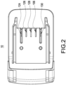
Fig. 2 shows an appearance view of the battery apparatus of the present disclosure. -
Fig. 3 shows a block diagram of the second embodiment of the battery apparatus of the present disclosure. -
Fig. 4 shows a circuit diagram of an embodiment of the battery identification circuit and the battery wakeup circuit of the present disclosure. - In the present disclosure, numerous specific details are provided, to provide a comprehensive understanding of embodiments of the present disclosure. However, those skilled in the art may understand that the present disclosure may be practiced without one or more of these specific details. In other instances, well-known details are not shown or described to avoid obscuring features of the present disclosure. The technical content and the detailed description of the present disclosure are as follows with reference to the figures.
-
Fig. 1 shows a block diagram of the first embodiment of thebattery apparatus 10 of the present disclosure.Fig. 2 shows an appearance view of thebattery apparatus 10 of the present disclosure. Abattery apparatus 10 of the present disclosure is applied to anelectronic apparatus 20. Thebattery apparatus 10 includes abattery management system 102, a plurality ofbatteries 104, an identification-and-wakeup integratedport 106, a batterypositive terminal 124, a chargingpositive terminal 126, atemperature port 128, a batterynegative terminal 130, afuse 132, anautomatic control protector 134, anovervoltage protection circuit 136, a negativetemperature coefficient thermistor 138, and aswitch component 140. Thebattery management system 102 includes abattery identification circuit 108, abattery wakeup circuit 110, amicroprocessor 122, and a self-holding (namely, self-maintenance)circuit 144. The components mentioned above are electrically connected to each other. - The
electronic apparatus 20 shown inFig. 1 is a charger. Theelectronic apparatus 20 includes an electronic-side chargingpositive terminal 204, anintegration port 206, atemperature sensing terminal 208, an electronic-side batterynegative terminal 210, acharging controller 212, a metal oxide semiconductorfield effect transistor 214, apower supply 216, and a low-dropout regulator 218. The components mentioned above are electrically connected to each other. - The
electronic apparatus 20 transmits afirst voltage 202 to thebattery identification circuit 108 and thebattery wakeup circuit 110 of thebattery management system 102 through the identification-and-wakeup integratedport 106. Thebattery identification circuit 108 of thebattery management system 102 is configured to receive thefirst voltage 202 through the identification-and-wakeup integratedport 106 to inform theelectronic apparatus 20 of a type (described in detail later) of thebatteries 104. Thebattery wakeup circuit 110 of thebattery management system 102 is configured to receive thefirst voltage 202 through the identification-and-wakeup integratedport 106 to wake up the battery management system 102 (described in detail later). Thefirst voltage 202 is 5 volts or 3.3 volts. - In a normal condition, the procedures for inserting the
battery apparatus 10 into the charger for charging are as follows: the charger provides thefirst voltage 202 to the identification-and-wakeup integratedport 106 and thetemperature port 128 to determine the type of thebatteries 104 and the temperature of thebatteries 104, and to utilize the identification-and-wakeup integratedport 106 to wake up thebattery management system 102; the charger detects the voltage of thebatteries 104; the charger receives a temperature feedback signal (not shown inFig. 1 ) through thetemperature port 128 to know that thebattery management system 102 has been awakened (described in detail later); after the charger determines the type of thebatteries 104 and detects the voltage of thebatteries 104, the charger starts charging thebatteries 104. - In an abnormal situation, which means that when the
batteries 104 are being charged, if thebattery management system 102 detects that thebatteries 104 are abnormal, thebattery management system 102 turns off theswitch component 140, so the charger no longer receives the temperature feedback signal through the negativetemperature coefficient thermistor 138, so the charger determines that thebattery apparatus 10 is abnormal, and then the charger stops charging thebatteries 104. - The
switch component 140 is a MOSFET (such as an N-type MOSFET), and the negativetemperature coefficient thermistor 138 is a 10K ohms negative temperature coefficient thermistor. The charger and an electric hand tool (namely, theelectronic apparatus 20 shown inFig. 3 ) further include a resistor (not shown inFig. 1 ) with a resistance value of 10K ohms connected in series with the negativetemperature coefficient thermistor 138, and an ADC (analog-to-digital converter, not shown inFig. 1 ) is set between the 10K ohms resistor and thetemperature sensing terminal 208. - When the
battery apparatus 10 is in a sleep mode, thebattery management system 102 turns off theswitch component 140, so that theelectronic apparatus 20 is not able to measure the resistance value of the negativetemperature coefficient thermistor 138. After theelectronic apparatus 20 wakes up thebattery apparatus 10, thebattery management system 102 turns on theswitch component 140, so that theelectronic apparatus 20 receives the temperature feedback signal to know that thebattery management system 102 has been awakened, and then the charger as shown inFig. 1 charges thebatteries 104, and the electric hand tool as shown inFig. 3 may be operated. If thebattery apparatus 10 is not awakened, the charger as shown inFig. 1 will not charge thebatteries 104, and the electric hand tool as shown inFig. 3 cannot be operated. -
Fig. 3 shows a block diagram of the second embodiment of thebattery apparatus 10 of the present disclosure. The descriptions of the elements shown inFig. 3 which are the same as the elements shown inFig. 1 are not repeated here for brevity. Theelectronic apparatus 20 shown inFig. 3 is an electric hand tool. Theelectronic apparatus 20 includes an electronic-side batterypositive terminal 220, anintegration port 206, atemperature sensing terminal 208, an electronic-side batterynegative terminal 210, an electronic-side microcontroller 222, a metal oxide semiconductorfield effect transistor 214, apower circuit 224, and a plurality of electronic-side resistors 226. The components mentioned above are electrically connected to each other. -
Fig. 4 shows a circuit diagram of an embodiment of thebattery identification circuit 108 and thebattery wakeup circuit 110 of the present disclosure. Please refer to bothFig. 1 andFig. 3 . Thebattery identification circuit 108 includes an identification-side resistor 112 and an identification-side capacitor 114. Thebattery wakeup circuit 110 includes aSchottky diode 116, afirst switch sub-circuit 118, and asecond switch sub-circuit 120. The components mentioned above are electrically connected to each other. - The identification-
side resistor 112 is set by the circuit designer, so that different types of thebatteries 104 have different identification-side resistors 112. For example, the resistance value of the identification-side resistor 112 of thebatteries 104 of model 21700/5S1P (6A charging) is set to 5.5K ohms; the resistance value of the identification-side resistor 112 of thebatteries 104 of model 21700/5S2P (6A charging) is set to 47K ohms; the resistance value of the identification-side resistor 112 of thebatteries 104 of model 18650/5S1P (4A charging) is set to 1K ohm; the resistance value of the identification-side resistor 112 of thebatteries 104 of model 18650/5S2P (6A charging) is set to 1.8K ohm. - The
electronic apparatus 20 further includes a resistor (not shown inFig.4 ) connected in series with the identification-side resistor 112. For example, for the charger as shown inFig. 1 , a 100K ohms resistor is set; for the electric hand tool shown inFig. 3 , if thefirst voltage 202 transmitted is 5 volts, a 2K ohms resistor is set, and if thefirst voltage 202 transmitted is 3.3 volts, a 1K ohms resistor is set. Moreover, thefirst voltage 202 transmitted by the charger as shown inFig. 1 is 5 volts, and thefirst voltage 202 transmitted by the electric hand tool as shown inFig. 3 may be 5 volts or 3.3 volts. Then, utilizing the Ohm's law, the resistor series formula, and so on, when the charger or the electric hand tool is connected to thebattery apparatus 10, the charger or the electric hand tool may know the resistance value of the identification-side resistor 112 to determine the type of thebatteries 104. - Moreover, the
battery apparatus 10 may further include theSchottky diode 116, wherein an anode of theSchottky diode 116 is connected to the identification-and-wakeup integratedport 106 and thebattery identification circuit 108, and a cathode of theSchottky diode 116 is connected to thebattery wakeup circuit 110. Theelectronic apparatus 20 transmits thefirst voltage 202 to thebattery wakeup circuit 110 through the identification-and-wakeup integratedport 106 and theSchottky diode 116. When two detection circuits (for example, thebattery wakeup circuit 110 and the battery identification circuit 108) are used in parallel, there may be a problem of loading effect; theSchottky diode 116 of the present disclosure is used to prevent thebattery wakeup circuit 110 and thebattery identification circuit 108 from affecting each other; therefore, the present disclosure does not just simply combine the identification port with the wakeup port. - Moreover, the
electronic apparatus 20 transmits thefirst voltage 202 to thefirst switch sub-circuit 118 through the identification-and-wakeup integration port 106 and theSchottky diode 116 to turn on thefirst switch sub-circuit 118. When thefirst switch sub-circuit 118 is turned on, thesecond switch sub-circuit 120 is configured to be turned on, so that thebatteries 104 are configured to transmit asecond voltage 142 to themicroprocessor 122 through the second switch sub-circuit 120 to drive themicroprocessor 122 to wake up thebattery management system 102. - Moreover, the
battery management system 102 further includes the self-holdingcircuit 144 electrically connected to themicroprocessor 122 and thebattery wakeup circuit 110. After themicroprocessor 122 is driven, themicroprocessor 122 is configured to utilize the self-holdingcircuit 144 to turn on or off thesecond switch sub-circuit 120. - Moreover, the
first switch sub-circuit 118 includes afirst resistor 146, afirst capacitor 148, asecond resistor 150, and afirst transistor 152. Thesecond switch sub-circuit 120 includes athird resistor 154 and asecond transistor 156. Thefirst resistor 146 is electrically connected to theSchottky diode 116. Thefirst capacitor 148 is electrically connected to thefirst resistor 146. Thesecond resistor 150 is electrically connected to thefirst resistor 146 and thefirst capacitor 148. Thefirst transistor 152 is electrically connected to thefirst resistor 146, thefirst capacitor 148, thesecond resistor 150, and thesecond switch sub-circuit 120. Thethird resistor 154 is electrically connected to thefirst transistor 152, thebatteries 104, and the self-holdingcircuit 144. Thesecond transistor 156 is electrically connected to thefirst transistor 152, the batteries104, the self-holdingcircuit 144, thethird resistor 154, and themicroprocessor 122. - The advantage of the present disclosure is to reduce the number of ports of the battery apparatus. Moreover, the identification-and-wakeup integrated
port 106 has two functions: first, the charger or the electric hand tool may identify the type of thebatteries 104 through the identification-and-wakeup integratedport 106; second, thebattery management system 102 is awakened through the identification-and-wakeup integratedport 106.
Claims (10)
- A battery apparatus (10) applied to an electronic apparatus (20), the battery apparatus (10) comprising:a battery management system (102);a plurality of batteries (104) electrically connected to the battery management system (102); andan identification-and-wakeup integrated port (106) electrically connected to the battery management system (102),wherein the electronic apparatus (20) transmits a first voltage (202) to the battery management system (102) through the identification-and-wakeup integrated port (106); the battery management system (102) is configured to receive the first voltage (202) through the identification-and-wakeup integrated port (106) to inform the electronic apparatus (20) of a type of the batteries (104); the battery management system (102) is configured to receive the first voltage (202) through the identification-and-wakeup integrated port (106) to wake up the battery management system (102).
- The battery apparatus (10) of claim 1, wherein the battery management system (102) comprises:a battery identification circuit (108) electrically connected to the identification-and-wakeup integrated port (106),wherein the electronic apparatus (20) transmits the first voltage (202) to the battery identification circuit (108) through the identification-and-wakeup integrated port (106); the battery identification circuit (108) is configured to receive the first voltage (202) through the identification-and-wakeup integrated port (106) to inform the electronic apparatus (20) of the type of the batteries (104).
- The battery apparatus (10) of claim 2, wherein the battery management system (102) further comprises:a battery wakeup circuit (110) electrically connected to the batteries (104), the identification-and-wakeup integrated port (106), and the battery identification circuit (108),wherein the electronic apparatus (20) transmits the first voltage (202) to the battery wakeup circuit (110) through the identification-and-wakeup integrated port (106); the battery wakeup circuit (110) is configured to receive the first voltage (202) through the identification-and-wakeup integrated port (106) to wake up the battery management system (102).
- The battery apparatus (10) of claim 3, wherein the battery identification circuit (108) comprises:
an identification-side resistor (112) electrically connected to the identification-and-wakeup integrated port (106) and the battery wakeup circuit (110). - The battery apparatus (10) of claim 4, wherein the battery identification circuit (108) further comprises:
an identification-side capacitor (114) electrically connected to the identification-and-wakeup integrated port (106), the battery wakeup circuit (110), and the identification-side resistor (112). - The battery apparatus (10) of claim 5, wherein the battery wakeup circuit (110) comprises:
a schottky diode (116) electrically connected to the identification-and-wakeup integrated port (106) and the battery identification circuit (108). - The battery apparatus (10) of claim 6, wherein the battery wakeup circuit (110) further comprises:
a first switch sub-circuit (118) electrically connected to the schottky diode (116). - The battery apparatus (10) of claim 7, wherein the battery wakeup circuit (110) further comprises:
a second switch sub-circuit (120) electrically connected to the first switch sub-circuit (118) and the batteries (104). - The battery apparatus (10) of claim 8, wherein the battery management system (102) further comprises:
a microprocessor (122) electrically connected to the battery wakeup circuit (110). - The battery apparatus (10) of claim 9, wherein the first voltage (202) is 5 volts or 3.3 volts.
Applications Claiming Priority (1)
| Application Number | Priority Date | Filing Date | Title |
|---|---|---|---|
| TW112100260A TWI867401B (en) | 2023-01-04 | 2023-01-04 | Battery apparatus with identification-and-wakeup integrated port |
Publications (2)
| Publication Number | Publication Date |
|---|---|
| EP4398444A2 true EP4398444A2 (en) | 2024-07-10 |
| EP4398444A3 EP4398444A3 (en) | 2024-07-31 |
Family
ID=89430233
Family Applications (1)
| Application Number | Title | Priority Date | Filing Date |
|---|---|---|---|
| EP23218331.9A Pending EP4398444A3 (en) | 2023-01-04 | 2023-12-19 | Battery apparatus with identification-and-wakeup integrated port |
Country Status (3)
| Country | Link |
|---|---|
| US (1) | US20240222717A1 (en) |
| EP (1) | EP4398444A3 (en) |
| TW (1) | TWI867401B (en) |
Family Cites Families (7)
| Publication number | Priority date | Publication date | Assignee | Title |
|---|---|---|---|---|
| JP2007520180A (en) * | 2003-10-14 | 2007-07-19 | ブラック アンド デッカー インク | Secondary battery, power tool, charger, and protection method, protection circuit, and protection device for battery pack adapted to provide protection from battery pack failure conditions |
| US8823321B2 (en) * | 2010-12-30 | 2014-09-02 | The Gillette Company—South Boston | Single wire battery pack temperature and identification method |
| WO2013051157A1 (en) * | 2011-10-07 | 2013-04-11 | 日立ビークルエナジー株式会社 | Battery monitoring system, host controller, and battery monitoring device |
| CN208890421U (en) * | 2018-09-28 | 2019-05-21 | 深圳和而泰智能控制股份有限公司 | A kind of electric tool |
| KR102869522B1 (en) * | 2019-11-13 | 2025-10-10 | 삼성에스디아이 주식회사 | Battery system and method of allocating CAN ID |
| CN212500002U (en) * | 2020-05-19 | 2021-02-09 | 合肥国轩高科动力能源有限公司 | Electric automobile awakening circuit |
| CN217035747U (en) * | 2022-01-05 | 2022-07-22 | 东莞新能安科技有限公司 | Wake-up detection circuit, battery management system and battery pack |
-
2023
- 2023-01-04 TW TW112100260A patent/TWI867401B/en active
- 2023-12-19 EP EP23218331.9A patent/EP4398444A3/en active Pending
- 2023-12-20 US US18/391,625 patent/US20240222717A1/en active Pending
Also Published As
| Publication number | Publication date |
|---|---|
| TW202429795A (en) | 2024-07-16 |
| TWI867401B (en) | 2024-12-21 |
| US20240222717A1 (en) | 2024-07-04 |
| EP4398444A3 (en) | 2024-07-31 |
Similar Documents
| Publication | Publication Date | Title |
|---|---|---|
| US11973366B2 (en) | Battery booster | |
| US5557188A (en) | Smart battery system and interface | |
| US11979045B2 (en) | Smart connection device, jump starter, and battery clamp | |
| US10541542B2 (en) | System and method for charging a battery pack | |
| KR101093888B1 (en) | Battery pack and its disconnection detection method | |
| US10622819B2 (en) | Rechargeable battery protection integrated circuit, rechargeable battery protection device, and battery pack | |
| WO2016119694A1 (en) | Battery protection circuit, electrical energy providing device and electronic device | |
| WO2020043128A1 (en) | Method and device for determining charging state of battery, and chip, battery and aircraft | |
| EP3858176B1 (en) | Output control circuit | |
| US20170331305A1 (en) | Adapter, power supply device, and over-discharge protection method | |
| US11742686B2 (en) | Battery device and battery charging system | |
| CN101325342B (en) | Charger for storage battery | |
| CN110797600B (en) | A charging method, device and socket device for battery load | |
| CN113141032A (en) | Portable food processor | |
| EP4398444A2 (en) | Battery apparatus with identification-and-wakeup integrated port | |
| CN201266846Y (en) | Charging equipment and combination of charging equipment and battery bag | |
| CN204464971U (en) | Battery protection circuit, power supply device and electronic device | |
| CN114142567A (en) | Battery management circuit and battery device | |
| CN201303255Y (en) | Battery pack | |
| CN201266847Y (en) | Battery bag and combination of battery bag and electrical device | |
| CN213920730U (en) | Fill electric pile plug from adaptation and charging safety protection circuit | |
| CN214045155U (en) | Charging protection circuit and charger | |
| US20220094178A1 (en) | Battery pack and electric device system | |
| CN217063349U (en) | Charging device with charging protection function | |
| US20040177282A1 (en) | Method and circuit for controlling battery charge and supply by microprocessor |
Legal Events
| Date | Code | Title | Description |
|---|---|---|---|
| PUAI | Public reference made under article 153(3) epc to a published international application that has entered the european phase |
Free format text: ORIGINAL CODE: 0009012 |
|
| STAA | Information on the status of an ep patent application or granted ep patent |
Free format text: STATUS: THE APPLICATION HAS BEEN PUBLISHED |
|
| PUAL | Search report despatched |
Free format text: ORIGINAL CODE: 0009013 |
|
| AK | Designated contracting states |
Kind code of ref document: A2 Designated state(s): AL AT BE BG CH CY CZ DE DK EE ES FI FR GB GR HR HU IE IS IT LI LT LU LV MC ME MK MT NL NO PL PT RO RS SE SI SK SM TR |
|
| AK | Designated contracting states |
Kind code of ref document: A3 Designated state(s): AL AT BE BG CH CY CZ DE DK EE ES FI FR GB GR HR HU IE IS IT LI LT LU LV MC ME MK MT NL NO PL PT RO RS SE SI SK SM TR |
|
| RIC1 | Information provided on ipc code assigned before grant |
Ipc: H01M 10/42 20060101ALI20240625BHEP Ipc: H02J 7/00 20060101AFI20240625BHEP |
|
| STAA | Information on the status of an ep patent application or granted ep patent |
Free format text: STATUS: REQUEST FOR EXAMINATION WAS MADE |
|
| 17P | Request for examination filed |
Effective date: 20250113 |