EP4398410A1 - Battery module - Google Patents
Battery module Download PDFInfo
- Publication number
- EP4398410A1 EP4398410A1 EP22909264.8A EP22909264A EP4398410A1 EP 4398410 A1 EP4398410 A1 EP 4398410A1 EP 22909264 A EP22909264 A EP 22909264A EP 4398410 A1 EP4398410 A1 EP 4398410A1
- Authority
- EP
- European Patent Office
- Prior art keywords
- cable
- cells
- branch
- inclined edge
- battery module
- Prior art date
- Legal status (The legal status is an assumption and is not a legal conclusion. Google has not performed a legal analysis and makes no representation as to the accuracy of the status listed.)
- Pending
Links
Images
Classifications
-
- H—ELECTRICITY
- H01—ELECTRIC ELEMENTS
- H01M—PROCESSES OR MEANS, e.g. BATTERIES, FOR THE DIRECT CONVERSION OF CHEMICAL ENERGY INTO ELECTRICAL ENERGY
- H01M10/00—Secondary cells; Manufacture thereof
- H01M10/42—Methods or arrangements for servicing or maintenance of secondary cells or secondary half-cells
- H01M10/48—Accumulators combined with arrangements for measuring, testing or indicating the condition of cells, e.g. the level or density of the electrolyte
- H01M10/482—Accumulators combined with arrangements for measuring, testing or indicating the condition of cells, e.g. the level or density of the electrolyte for several batteries or cells simultaneously or sequentially
-
- H—ELECTRICITY
- H01—ELECTRIC ELEMENTS
- H01M—PROCESSES OR MEANS, e.g. BATTERIES, FOR THE DIRECT CONVERSION OF CHEMICAL ENERGY INTO ELECTRICAL ENERGY
- H01M10/00—Secondary cells; Manufacture thereof
- H01M10/42—Methods or arrangements for servicing or maintenance of secondary cells or secondary half-cells
- H01M10/48—Accumulators combined with arrangements for measuring, testing or indicating the condition of cells, e.g. the level or density of the electrolyte
- H01M10/486—Accumulators combined with arrangements for measuring, testing or indicating the condition of cells, e.g. the level or density of the electrolyte for measuring temperature
-
- H—ELECTRICITY
- H01—ELECTRIC ELEMENTS
- H01M—PROCESSES OR MEANS, e.g. BATTERIES, FOR THE DIRECT CONVERSION OF CHEMICAL ENERGY INTO ELECTRICAL ENERGY
- H01M50/00—Constructional details or processes of manufacture of the non-active parts of electrochemical cells other than fuel cells, e.g. hybrid cells
- H01M50/20—Mountings; Secondary casings or frames; Racks, modules or packs; Suspension devices; Shock absorbers; Transport or carrying devices; Holders
- H01M50/204—Racks, modules or packs for multiple batteries or multiple cells
-
- H—ELECTRICITY
- H01—ELECTRIC ELEMENTS
- H01M—PROCESSES OR MEANS, e.g. BATTERIES, FOR THE DIRECT CONVERSION OF CHEMICAL ENERGY INTO ELECTRICAL ENERGY
- H01M50/00—Constructional details or processes of manufacture of the non-active parts of electrochemical cells other than fuel cells, e.g. hybrid cells
- H01M50/20—Mountings; Secondary casings or frames; Racks, modules or packs; Suspension devices; Shock absorbers; Transport or carrying devices; Holders
- H01M50/204—Racks, modules or packs for multiple batteries or multiple cells
- H01M50/207—Racks, modules or packs for multiple batteries or multiple cells characterised by their shape
- H01M50/209—Racks, modules or packs for multiple batteries or multiple cells characterised by their shape adapted for prismatic or rectangular cells
-
- H—ELECTRICITY
- H01—ELECTRIC ELEMENTS
- H01M—PROCESSES OR MEANS, e.g. BATTERIES, FOR THE DIRECT CONVERSION OF CHEMICAL ENERGY INTO ELECTRICAL ENERGY
- H01M50/00—Constructional details or processes of manufacture of the non-active parts of electrochemical cells other than fuel cells, e.g. hybrid cells
- H01M50/20—Mountings; Secondary casings or frames; Racks, modules or packs; Suspension devices; Shock absorbers; Transport or carrying devices; Holders
- H01M50/298—Mountings; Secondary casings or frames; Racks, modules or packs; Suspension devices; Shock absorbers; Transport or carrying devices; Holders characterised by the wiring of battery packs
-
- H—ELECTRICITY
- H01—ELECTRIC ELEMENTS
- H01M—PROCESSES OR MEANS, e.g. BATTERIES, FOR THE DIRECT CONVERSION OF CHEMICAL ENERGY INTO ELECTRICAL ENERGY
- H01M50/00—Constructional details or processes of manufacture of the non-active parts of electrochemical cells other than fuel cells, e.g. hybrid cells
- H01M50/50—Current conducting connections for cells or batteries
- H01M50/502—Interconnectors for connecting terminals of adjacent batteries; Interconnectors for connecting cells outside a battery casing
- H01M50/509—Interconnectors for connecting terminals of adjacent batteries; Interconnectors for connecting cells outside a battery casing characterised by the type of connection, e.g. mixed connections
- H01M50/51—Connection only in series
-
- H—ELECTRICITY
- H01—ELECTRIC ELEMENTS
- H01M—PROCESSES OR MEANS, e.g. BATTERIES, FOR THE DIRECT CONVERSION OF CHEMICAL ENERGY INTO ELECTRICAL ENERGY
- H01M50/00—Constructional details or processes of manufacture of the non-active parts of electrochemical cells other than fuel cells, e.g. hybrid cells
- H01M50/50—Current conducting connections for cells or batteries
- H01M50/502—Interconnectors for connecting terminals of adjacent batteries; Interconnectors for connecting cells outside a battery casing
- H01M50/519—Interconnectors for connecting terminals of adjacent batteries; Interconnectors for connecting cells outside a battery casing comprising printed circuit boards [PCB]
-
- H—ELECTRICITY
- H01—ELECTRIC ELEMENTS
- H01M—PROCESSES OR MEANS, e.g. BATTERIES, FOR THE DIRECT CONVERSION OF CHEMICAL ENERGY INTO ELECTRICAL ENERGY
- H01M50/00—Constructional details or processes of manufacture of the non-active parts of electrochemical cells other than fuel cells, e.g. hybrid cells
- H01M50/50—Current conducting connections for cells or batteries
- H01M50/543—Terminals
- H01M50/547—Terminals characterised by the disposition of the terminals on the cells
- H01M50/548—Terminals characterised by the disposition of the terminals on the cells on opposite sides of the cell
-
- H—ELECTRICITY
- H01—ELECTRIC ELEMENTS
- H01M—PROCESSES OR MEANS, e.g. BATTERIES, FOR THE DIRECT CONVERSION OF CHEMICAL ENERGY INTO ELECTRICAL ENERGY
- H01M50/00—Constructional details or processes of manufacture of the non-active parts of electrochemical cells other than fuel cells, e.g. hybrid cells
- H01M50/50—Current conducting connections for cells or batteries
- H01M50/569—Constructional details of current conducting connections for detecting conditions inside cells or batteries, e.g. details of voltage sensing terminals
-
- Y—GENERAL TAGGING OF NEW TECHNOLOGICAL DEVELOPMENTS; GENERAL TAGGING OF CROSS-SECTIONAL TECHNOLOGIES SPANNING OVER SEVERAL SECTIONS OF THE IPC; TECHNICAL SUBJECTS COVERED BY FORMER USPC CROSS-REFERENCE ART COLLECTIONS [XRACs] AND DIGESTS
- Y02—TECHNOLOGIES OR APPLICATIONS FOR MITIGATION OR ADAPTATION AGAINST CLIMATE CHANGE
- Y02E—REDUCTION OF GREENHOUSE GAS [GHG] EMISSIONS, RELATED TO ENERGY GENERATION, TRANSMISSION OR DISTRIBUTION
- Y02E60/00—Enabling technologies; Technologies with a potential or indirect contribution to GHG emissions mitigation
- Y02E60/10—Energy storage using batteries
Definitions
- the present disclosure relates to technical field of batteries, and in particular to a battery module.
- battery modules are widely applied due to their advantages of high energy density and stable power storage performance.
- a battery module with a two-outlet pole cell the positive and negative poles of each cell are arranged on both sides of the cell.
- adjacent cells are arranged in reverse direction, which makes the collection of voltage and temperature signals of the cells more complicated.
- An existing collection assembly is commonly adopted with wire harnesses, while the number of the wire harnesses is large and the connection path is complex, such that the overall space occupied by the collection assembly is large, which results in a reduction in the energy density of the battery module.
- a battery module including:
- the terms “mounted”, “connected”, “coupled” are to be broadly construed.
- it may be a fixed connection or a removable connection, a mechanical connection or an electrical connection, a direct connection or an indirect connection through an intermediate medium, or a connection within two elements.
- the specific meaning of the above terms in the present disclosure can be understood in specific cases.
- a first feature being “above” or “under” a second feature may include the first and second features being in direct contact, or the first and second features being in contact not directly but through another feature between them.
- the first feature being “above”, “over” and “on top of” the second feature includes the first feature being directly above and diagonally above the second feature, or simply indicates that the first feature is horizontally higher than the second feature.
- the first feature being “below”, “under”, and “beneath” the second feature includes the first feature being directly below and diagonally below the second feature, or simply indicates that the first feature is horizontally lower than the second feature.
- a positive pole and a negative pole post of the cell are arranged on both sides of the cell.
- adjacent cells are arranged in reverse direction, which makes the collection of voltage and temperature signals of the cells more complicated.
- An existing collection assembly is commonly adopted with wire harnesses, while the number of the wire harnesses is large and the connection path is complex, such that the overall space occupied by the collection assembly is large, which results in a reduction in the energy density of the battery module. Therefore, the present embodiments provide a battery module to solve the above problems.
- the battery module includes a housing, and multiple cells and two collection assemblies that are disposed in the housing.
- the multiple cells are arranged in a straight line.
- the multiple cells are arranged in a direction extending along a thickness direction of the cells to form a rectangular-shaped cell set.
- the two collection assemblies are adopted with Flexible Flat Cables (FFCs) instead of wire harnesses to obtain voltage and temperature signals of the cells.
- FFCs Flexible Flat Cables
- a positive terminal of each cell is arranged on a side of the cell, and a negative terminal of the cell is arranged on another side of the cell opposite to the positive terminal.
- Each adjacent two cells are arranged in reverse direction, such that the positive terminal of one cell is arranged on the same side as the negative terminal of the other adjacent cell.
- One of the two collection assemblies is electrically connected to the positive terminal or the negative terminal on a side of the cell set, and the other of the two collection assemblies is electrically connected to the negative terminal positive terminal or the negative terminal on the other side of the cell set, i.e., the two collection assemblies are arranged on the two sides of the cell set to obtain the voltage and temperature signals.
- each collection assembly includes a first cable 4 and a second cable 5, and each of the first cable 4 and the second cable 5 may be specifically a Flexible Flat Cable (FFC); where the first cable 4 is configured to obtain the voltage and temperature signals of some cells, the second cable 5 is configured to obtain the voltage and temperature signals of some cells, and the two collection assemblies can obtain the voltage signals of all the cells.
- the first cable 4 includes a first inclined edge 41 and the second cable 5 includes a second inclined edge 51, and the first inclined edge 41 and the second inclined edge 51 are arranged in parallel to reduce space occupation.
- the width of the FFC is the sum of the widths of the 10 branches; while when two FFCs are provided in the battery module and each FFC includes 5 branches, i.e., the width of the one FFC is the sum of the widths of the 5 branches and the arrangement of the two FFCs satisfies that the two FFCs do not stack on the width direction, the overall width of the two FFCs is the sum of the widths of the 5 branches, which is half of the width when only one FFC is provided.
- a gap between the first inclined edge 41 and the second inclined edge 51 is as small as possible.
- Adopting the FFC instead of the wire harness can effectively reduce the occupied space.
- the FFC has too many branches, making the width of the FFC larger.
- the present discloses may reduce the overall width and save space by arranging the first cable 4 and the second cable 5 and making the first cable 4 and the second cable 5 parallel to each other through the first inclined edge 41 and the second inclined edge 51. Therefore, the battery module may reduce the space occupied by the collection assemblies and improve the energy density of the battery module.
- the first cable 4 forks out first branches 42 and a second branch 43 at the first inclined edge 41, the first branches 42 being electrically connected to some cells to collect the voltage signals of the cells, and the second branch 43 being configured to collect the temperature signals.
- the length direction of the trunk circuits of the first cable 4 and the second cable 5 are in the same direction as the thickness direction of the cells.
- each collection assembly further includes a first temperature-sensitive package 6, the first temperature-sensitive package 6 being configured to collect the temperature signals.
- the second branch 43 is folded twice to form a Z-shape, such that an end of the second branch 43 is connected to the first temperature-sensitive package 6.
- the folds are all at a right angle, but of course, the angle of the folds may be adjusted according to the length of the second branch 43 and the distance between the first temperature-sensitive package 6 and the first cable 4.
- the first temperature-sensitive package 6 is connected to a corresponding cell, when the cell undergoes expansion and deformation, the first temperature-sensitive package 6 is movable together, and the folding of the second branch 43 may enable the second branch 43 to be movable with the cell to avoid disconnection.
- the end of the second branch 43 is connected to the first temperature-sensitive package 6 by a welding process.
- a structural adhesive is provided at the welding position to fix and protect the welding position.
- the second cable 5 includes a third inclined edge 52 opposite to the second inclined edge 51, and the second cable 5 forks out third branches 53 and a fourth branch 54 at the third inclined edge 52.
- the third branches 53 are electrically connected to some cells to collect the voltage signals, and the fourth branch 54 is configured to collect the temperature signals.
- the third branch 53 is folded once to form an L-shape, such that an end of the third branch 53 is electrically connected to a corresponding cell.
- the folding of the third branch 53 may enable the third branch 53 to be movable with the cell to avoid disconnection.
- each collection assembly further includes a second temperature-sensitive package 7, the second temperature-sensitive package 7 being configured to collect the temperature signals.
- the second cable 5 can transmit the temperature signals measured by the second temperature-sensitive package 7.
- the fourth branch 54 is folded twice to form a Z-shape, such that an end of the fourth branch 54 is connected to the second temperature-sensitive package 7.
- the folds are all at a right angle, but of course, the angle of the folds may also be adjusted according to the length of the fourth branch 54 and the distance between the second temperature-sensitive package 7 and the second cable 5.
- the second temperature-sensitive package 7 is connected to a corresponding cell, when the cell expands and deforms, the second temperature-sensitive package 7 is movable together, and the folding of the fourth branch 54 may enable the fourth branch 54 to be movable with the cell to avoid disconnection.
- the end of the fourth branch 54 is connected to the second temperature-sensitive package 7 by a welding process.
- a structural adhesive is provided at the welding position to fix and protect the welding position.
- the second inclined edge 51 is parallel to the third inclined edge 52, i.e. the second cable 5 has a parallelogram structure. Since the first inclined edge 41 is parallel to the second inclined edge 51, the first cable 4 and the second cable 5 can be set to be of the same length and width, resulting in the overall width of the first cable 4 and the second cable 5 being half the width in the case with only one FFC provided.
- each collection assembly further includes a cable board 8, which may be specifically a Printed Circuit Board (PCB).
- a first summary end of the first cable 4 is arranged on a side of the cable board 8, and a second summary end of the second cable 5 is arranged on another side of the cable board 8 opposite to the first summary end of the first cable 4.
- the setting of the two on the two opposite sides reduces the occupancy of the cable board 8, and thus reduces the size of the cable board 8.
- the first summary end and the second summary end are simultaneously welded on the cable board 8 with a double-sided high temperature welding process, which may reduce the process steps and improve work efficiency.
- a structural adhesive is provided at the welding position of the first summary end and the cable board 8, and at the welding position of the second summary end and the cable board 8 to fix and protect the welding positions.
- a flame-resistant plate is attached to a side of the cable board 8 to protect the PCB8 in case of temperature abnormality of the cells.
- a reinforcement member is further arranged on the side of the PCB 8 where the flame-resistant plate is provided.
- the reinforcement member is foam, which plays a supporting role and a cushioning protective role.
- each collection assembly further includes a collection connector 13, which is electrically connected to the cable board 8, and the collection connector 13 is further electrically connected to a battery management system, such that the voltage and temperature signals of the cells can be transmitted to the battery management system.
- the first temperature-sensitive package 6 and the second temperature-sensitive package 7 are both attached to the film 9 by adhesive backing, and because the strength of the film 9 is insufficient, a reinforcement member may be arranged at an attachment position.
- the first temperature-sensitive package 6 and the second temperature-sensitive package 7 are arranged on a side of the film 9, and the reinforcement member is arranged on the other side of the film 9.
- the reinforcement member can support the film 9 to ensure the attachment strength.
- the reinforcement member is foam, which can provide cushioning to protect loose components while supporting the film 9 to ensure the attachment strength.
- each of the collection assemblies further includes multiple support plates 12 connected to the housing, and the support plates 12 are configured to fix the relative positions between the connectors 10, the film 9, and the housing.
- each support plate 12 is arranged with a riveting post 121, the film 9 defines a riveting hole, and a corresponding connector 10 defines a positioning hole 101.
- the riveting post 121 passes through the riveting hole and the positioning hole 101 in turn and is riveted to the corresponding connector 10 to ensure that there is no loosening and relative movement between the three during the subsequent use of the battery module.
Landscapes
- Chemical & Material Sciences (AREA)
- Chemical Kinetics & Catalysis (AREA)
- Electrochemistry (AREA)
- General Chemical & Material Sciences (AREA)
- Engineering & Computer Science (AREA)
- Manufacturing & Machinery (AREA)
- Battery Mounting, Suspending (AREA)
Abstract
Description
- The present disclosure relates to technical field of batteries, and in particular to a battery module.
- As the application of electric vehicles becomes more and more widespread, battery modules are widely applied due to their advantages of high energy density and stable power storage performance. In a battery module with a two-outlet pole cell, the positive and negative poles of each cell are arranged on both sides of the cell. To facilitate series connection of the cells, adjacent cells are arranged in reverse direction, which makes the collection of voltage and temperature signals of the cells more complicated. An existing collection assembly is commonly adopted with wire harnesses, while the number of the wire harnesses is large and the connection path is complex, such that the overall space occupied by the collection assembly is large, which results in a reduction in the energy density of the battery module.
- It is an object of the present disclosure to provide a battery module that may reduce the occupied space of a collection assembly and improve the energy density of the battery module.
- A battery module, including:
- a plurality of cells, arranged in a straight line; wherein each cell is arranged with a positive terminal and a negative terminal; a positive terminal of each cell is arranged on a side of the cell, and a negative terminal of the cell is arranged on another side of the cell opposite to the positive terminal; each adjacent two of the plurality of cells are arranged in a reverse direction, such that the positive terminal of one of the adjacent two of the plurality of cells is arranged on a same side as the negative terminal of the other of the adjacent two of the plurality of cells; and
- two collection assemblies; wherein one of the two collection assemblies is electrically connected to the positive terminal or the negative terminal on a side, and the other of the two collection assemblies is electrically connected to the negative terminal positive terminal or the negative terminal on another side; each collection assembly includes:
- a first cable, configured to obtain voltage signals and temperature signals of some of the plurality of cells; wherein the first cable includes a first inclined edge; and
- a second cable, configured to obtain the voltage signals and the temperature signals of others of the plurality of cells; wherein the second cable includes a second inclined edge, and the first inclined edge and the second inclined edge are arranged in parallel.
-
-
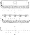
FIG. 1 is a partial structural schematic view of a battery module according to some embodiments of the present disclosure. -
FIG. 2 is a partial structural schematic view of two collection assemblies according to some embodiments of the present disclosure. -
FIG. 3 is a partial structural schematic view of a collection assembly according to some embodiments of the present disclosure. -
- 4, first cable; 41, first inclined edge; 42, first branch; 43, second branch;
- 5, second cable; 51, second inclined edge; 52, third inclined edge; 53, third branch; 54, fourth branch;
- 6, first temperature-sensitive package; 7, second temperature-sensitive package; 8, cable board; 9, film;
- 10, connection member; 101, positioning hole;
- 11, collection member;
- 12, support plate; 121, riveting post;
- 13, collection connector.
- In the description of the present disclosure, it is to be noted that, unless otherwise expressly provided and limited, the terms "mounted", "connected", "coupled" are to be broadly construed. For example, it may be a fixed connection or a removable connection, a mechanical connection or an electrical connection, a direct connection or an indirect connection through an intermediate medium, or a connection within two elements. For those skilled in the art, the specific meaning of the above terms in the present disclosure can be understood in specific cases.
- In the present disclosure, unless otherwise expressly provided and limited, a first feature being "above" or "under" a second feature may include the first and second features being in direct contact, or the first and second features being in contact not directly but through another feature between them. Furthermore, the first feature being "above", "over" and "on top of" the second feature includes the first feature being directly above and diagonally above the second feature, or simply indicates that the first feature is horizontally higher than the second feature. The first feature being "below", "under", and "beneath" the second feature includes the first feature being directly below and diagonally below the second feature, or simply indicates that the first feature is horizontally lower than the second feature.
- In a battery module with a two-outlet pole cell, a positive pole and a negative pole post of the cell are arranged on both sides of the cell. To facilitate series connection of the cells, adjacent cells are arranged in reverse direction, which makes the collection of voltage and temperature signals of the cells more complicated. An existing collection assembly is commonly adopted with wire harnesses, while the number of the wire harnesses is large and the connection path is complex, such that the overall space occupied by the collection assembly is large, which results in a reduction in the energy density of the battery module. Therefore, the present embodiments provide a battery module to solve the above problems.
- As shown in
FIGS. 1-2 , the battery module includes a housing, and multiple cells and two collection assemblies that are disposed in the housing. The multiple cells are arranged in a straight line. In some embodiments, the multiple cells are arranged in a direction extending along a thickness direction of the cells to form a rectangular-shaped cell set. The two collection assemblies are adopted with Flexible Flat Cables (FFCs) instead of wire harnesses to obtain voltage and temperature signals of the cells. - Specifically, a positive terminal of each cell is arranged on a side of the cell, and a negative terminal of the cell is arranged on another side of the cell opposite to the positive terminal. Each adjacent two cells are arranged in reverse direction, such that the positive terminal of one cell is arranged on the same side as the negative terminal of the other adjacent cell. One of the two collection assemblies is electrically connected to the positive terminal or the negative terminal on a side of the cell set, and the other of the two collection assemblies is electrically connected to the negative terminal positive terminal or the negative terminal on the other side of the cell set, i.e., the two collection assemblies are arranged on the two sides of the cell set to obtain the voltage and temperature signals.
- As shown in
FIG. 3 , each collection assembly includes afirst cable 4 and asecond cable 5, and each of thefirst cable 4 and thesecond cable 5 may be specifically a Flexible Flat Cable (FFC); where thefirst cable 4 is configured to obtain the voltage and temperature signals of some cells, thesecond cable 5 is configured to obtain the voltage and temperature signals of some cells, and the two collection assemblies can obtain the voltage signals of all the cells. In some embodiments, thefirst cable 4 includes a firstinclined edge 41 and thesecond cable 5 includes a secondinclined edge 51, and the firstinclined edge 41 and the secondinclined edge 51 are arranged in parallel to reduce space occupation. For example, when only one FFC is provided in the battery module and the FFC includes 10 branches, the width of the FFC is the sum of the widths of the 10 branches; while when two FFCs are provided in the battery module and each FFC includes 5 branches, i.e., the width of the one FFC is the sum of the widths of the 5 branches and the arrangement of the two FFCs satisfies that the two FFCs do not stack on the width direction, the overall width of the two FFCs is the sum of the widths of the 5 branches, which is half of the width when only one FFC is provided. - In some embodiments, to make the overall length occupied by the
first cable 4 and thesecond cable 5 as small as possible, a gap between the firstinclined edge 41 and the secondinclined edge 51 is as small as possible. - Adopting the FFC instead of the wire harness can effectively reduce the occupied space. However, when the number of cells is large, the FFC has too many branches, making the width of the FFC larger. In response thereto, the present discloses may reduce the overall width and save space by arranging the
first cable 4 and thesecond cable 5 and making thefirst cable 4 and thesecond cable 5 parallel to each other through the firstinclined edge 41 and the secondinclined edge 51. Therefore, the battery module may reduce the space occupied by the collection assemblies and improve the energy density of the battery module. - In some embodiments, the
first cable 4 forks outfirst branches 42 and asecond branch 43 at the firstinclined edge 41, thefirst branches 42 being electrically connected to some cells to collect the voltage signals of the cells, and thesecond branch 43 being configured to collect the temperature signals. To ensure a compact structure inside the battery module, in some embodiments, the length direction of the trunk circuits of thefirst cable 4 and thesecond cable 5 are in the same direction as the thickness direction of the cells. - To facilitate the connection of the
first branch 42 with the cells, in some embodiments, thefirst branch 42 is folded once to form an L-shape, such that an end of thefirst branch 42 is electrically connected to a corresponding cell. It is known that the cell may expand and deform during use, and the folding of thefirst branch 42 may enable thefirst branch 42 to be movable with the cell to avoid disconnection. - In some embodiments, as shown in
FIGS. 2 and 3 , each collection assembly further includes a first temperature-sensitive package 6, the first temperature-sensitive package 6 being configured to collect the temperature signals. Thesecond branch 43 is folded twice to form a Z-shape, such that an end of thesecond branch 43 is connected to the first temperature-sensitive package 6. In some embodiments, the folds are all at a right angle, but of course, the angle of the folds may be adjusted according to the length of thesecond branch 43 and the distance between the first temperature-sensitive package 6 and thefirst cable 4. Similarly, since the first temperature-sensitive package 6 is connected to a corresponding cell, when the cell undergoes expansion and deformation, the first temperature-sensitive package 6 is movable together, and the folding of thesecond branch 43 may enable thesecond branch 43 to be movable with the cell to avoid disconnection. In some embodiments, the end of thesecond branch 43 is connected to the first temperature-sensitive package 6 by a welding process. In some embodiments, a structural adhesive is provided at the welding position to fix and protect the welding position. - In some embodiments, the
second cable 5 includes a thirdinclined edge 52 opposite to the secondinclined edge 51, and thesecond cable 5 forks outthird branches 53 and afourth branch 54 at the thirdinclined edge 52. Thethird branches 53 are electrically connected to some cells to collect the voltage signals, and thefourth branch 54 is configured to collect the temperature signals. - Similarly, the
third branch 53 is folded once to form an L-shape, such that an end of thethird branch 53 is electrically connected to a corresponding cell. When the cell expands and deforms, the folding of thethird branch 53 may enable thethird branch 53 to be movable with the cell to avoid disconnection. - In some embodiments, each collection assembly further includes a second temperature-
sensitive package 7, the second temperature-sensitive package 7 being configured to collect the temperature signals. Thesecond cable 5 can transmit the temperature signals measured by the second temperature-sensitive package 7. Thefourth branch 54 is folded twice to form a Z-shape, such that an end of thefourth branch 54 is connected to the second temperature-sensitive package 7. In some embodiments, the folds are all at a right angle, but of course, the angle of the folds may also be adjusted according to the length of thefourth branch 54 and the distance between the second temperature-sensitive package 7 and thesecond cable 5. Similarly, since the second temperature-sensitive package 7 is connected to a corresponding cell, when the cell expands and deforms, the second temperature-sensitive package 7 is movable together, and the folding of thefourth branch 54 may enable thefourth branch 54 to be movable with the cell to avoid disconnection. In some embodiments, the end of thefourth branch 54 is connected to the second temperature-sensitive package 7 by a welding process. In some embodiments, a structural adhesive is provided at the welding position to fix and protect the welding position. - In some embodiments, the second
inclined edge 51 is parallel to the thirdinclined edge 52, i.e. thesecond cable 5 has a parallelogram structure. Since the firstinclined edge 41 is parallel to the secondinclined edge 51, thefirst cable 4 and thesecond cable 5 can be set to be of the same length and width, resulting in the overall width of thefirst cable 4 and thesecond cable 5 being half the width in the case with only one FFC provided. - In some embodiments, each collection assembly further includes a
cable board 8, which may be specifically a Printed Circuit Board (PCB). A first summary end of thefirst cable 4 is arranged on a side of thecable board 8, and a second summary end of thesecond cable 5 is arranged on another side of thecable board 8 opposite to the first summary end of thefirst cable 4. Compared to the design where the first and second summary ends are arranged on a same side, the setting of the two on the two opposite sides reduces the occupancy of thecable board 8, and thus reduces the size of thecable board 8. In addition, the first summary end and the second summary end are simultaneously welded on thecable board 8 with a double-sided high temperature welding process, which may reduce the process steps and improve work efficiency. In some embodiments, a structural adhesive is provided at the welding position of the first summary end and thecable board 8, and at the welding position of the second summary end and thecable board 8 to fix and protect the welding positions. - In some embodiments, to protect the
cable board 8, a flame-resistant plate is attached to a side of thecable board 8 to protect the PCB8 in case of temperature abnormality of the cells. In some embodiments, a reinforcement member is further arranged on the side of thePCB 8 where the flame-resistant plate is provided. In some embodiments, the reinforcement member is foam, which plays a supporting role and a cushioning protective role. - In some embodiments, each collection assembly further includes a
collection connector 13, which is electrically connected to thecable board 8, and thecollection connector 13 is further electrically connected to a battery management system, such that the voltage and temperature signals of the cells can be transmitted to the battery management system. - Fixing each element of the collection assemblies enables that the collection assembly can be processed and molded first and then processed with the cells, thereby reducing the process difficulty, reducing the number of process steps, and thus improving the work efficiency. In some embodiments, each collection assembly further includes a
film 9, which may be made of polyethylene terephthalate (PET). It is known that the PET material is lightweight, which is conducive to reducing the quality of the collection assembly. Thefirst cable 4 and thesecond cable 5 are fixed to thefilm 9 to fix their relative positions, which is conducive to the subsequent connection with the cells. - In some embodiments, the first temperature-
sensitive package 6 and the second temperature-sensitive package 7 are both attached to thefilm 9 by adhesive backing, and because the strength of thefilm 9 is insufficient, a reinforcement member may be arranged at an attachment position. In some embodiments, the first temperature-sensitive package 6 and the second temperature-sensitive package 7 are arranged on a side of thefilm 9, and the reinforcement member is arranged on the other side of thefilm 9. The reinforcement member can support thefilm 9 to ensure the attachment strength. In some embodiments, the reinforcement member is foam, which can provide cushioning to protect loose components while supporting thefilm 9 to ensure the attachment strength. - In some embodiments, each collection assembly further includes
multiple connectors 10 and multiple collection members 11. Each of theconnectors 10 is electrically connected to corresponding adjacent two cells or to one of the cells at an end of the cell set. In some embodiments, theconnectors 10 are aluminum rows. The multiple collection members 11 are electrically connected to theconnectors 10 in a one-to-one correspondence. In some embodiments, the collection members 11 are nickel tabs. Thefirst branches 42 are electrically connected to some of the collection members 11 in a one-to-one correspondence, and thethird branches 53 are electrically connected to the remaining of the collection members 11 in a one-to-one correspondence. That is, thefirst cable 4 is electrically connected to the cells via the collection members 11, and thesecond cable 5 is electrically connected to the cells via theconnectors 10. - To fix the relative positions of the
connectors 10, in some embodiments, each of the collection assemblies further includesmultiple support plates 12 connected to the housing, and thesupport plates 12 are configured to fix the relative positions between theconnectors 10, thefilm 9, and the housing. Specifically, eachsupport plate 12 is arranged with ariveting post 121, thefilm 9 defines a riveting hole, and a correspondingconnector 10 defines apositioning hole 101. Theriveting post 121 passes through the riveting hole and thepositioning hole 101 in turn and is riveted to the correspondingconnector 10 to ensure that there is no loosening and relative movement between the three during the subsequent use of the battery module.
Claims (10)
- A battery module, comprising:a plurality of cells, arranged in a straight line; wherein each cell is arranged with a positive terminal and a negative terminal; the positive terminal of each cell is arranged on a side of the cell, and positive negative terminal of the cell is arranged on another side of the cell opposite to the positive terminal; each adjacent two of the plurality of cells are arranged in a reverse direction, such that the positive terminal of one of the adjacent two of the plurality of cells is arranged on a same side as the negative terminal of the other of the adj acent two of the plurality of cells; andtwo collection assemblies; wherein one of the two collection assemblies is electrically connected to the positive terminal or the negative terminal on a side, and the other of the two collection assemblies is electrically connected to the negative terminal positive terminal or the negative terminal on another side; each collection assembly comprises:a first cable (4), configured to obtain voltage signals and temperature signals of some of the plurality of cells; wherein the first cable (4) comprises a first inclined edge (41); anda second cable (5), configured to obtain the voltage signals and the temperature signals of others of the plurality of cells; wherein the second cable (5) comprises a second inclined edge (51), and the first inclined edge (41) and the second inclined edge (51) are arranged in parallel.
- The battery module according to claim 1, wherein the first cable (4) forks out a plurality of first branches (42) and a second branch (43) at the first inclined edge (41), the first branches (42) being electrically connected to the some of the plurality of cells, and the second branch (43) being configured to collect the temperature signals.
- The battery module according to claim 2, wherein the second cable (5) further comprises a third inclined edge (52) opposite to the second inclined edge (51), and the second cable (5) forks out a plurality of third branches (53) and a fourth branch (54) at the third inclined edge (52); the plurality of third branches (53) are electrically connected to the others of the plurality of cells, and the fourth branch (54) is configured to collect the temperature signals.
- The battery module according to claim 3, wherein the second inclined edge (51) is parallel to the third inclined edge (52).
- The battery module according to claim 2, wherein the first branch (42) is folded once to form an L-shape, such that an end of the first branch (42) is electrically connected to a corresponding cell; and/or
each collection assembly further comprises a first temperature-sensitive package (6), the first temperature-sensitive package (6) being configured to collect the temperature signals; the second branch (43) is folded twice to form a Z-shape, such that an end of the second branch (43) is connected to the first temperature-sensitive package (6). - The battery module according to claim 3, wherein the third branch (53) is folded once to form an L-shape, such that an end of the third branch (53) is electrically connected to a corresponding cell; and/or
each collection assembly further comprises a second temperature-sensitive package (7), the second temperature-sensitive package (7) being configured to collect the temperature signals; the fourth branch (54) is folded twice to form a Z-shape, such that an end of the fourth branch (54) is connected to the second temperature-sensitive package (7). - The battery module according to claim 3, wherein each collection assembly further comprises a cable board (8); a first summary end of the first cable (4) is arranged on a side of the cable board (8), and a second summary end of the second cable (5) is arranged on another side of the cable board (8) opposite to the first summary end of the first cable (4); the first summary end and the second summary end are simultaneously welded on the cable board (8) with a double-sided high temperature welding process.
- The battery module according to claim 7, wherein each collection assembly further comprises a film (9); the first cable (4) and the second cable (5) are fixed to the film (9).
- The battery module according to claim 8, wherein each collection assembly further comprises a plurality of connectors (10) and a plurality of collection members (11); each connector (10) is electrically connected to corresponding adjacent two of the plurality of cells or to one of the plurality of cells at an end; the plurality of collection members (11) are electrically connected to the plurality of connectors (10) in a one-to-one correspondence; the plurality of first branches (42) are electrically connected to some of the plurality of collection members (11) in a one-to-one correspondence, and the plurality of third branches (53) are electrically connected to a remaining of the plurality of collection members (11) in a one-to-one correspondence.
- The battery module according to claim 9, further comprising a housing; wherein the plurality of cells and the two collection assemblies are arranged in the housing; each collection assembly further comprises a plurality of support plates (12) connected to the housing, and each support plate (12) is arranged with a riveting post (121); the film (9) defines a riveting hole, and a corresponding connector (10) defines a positioning hole (101); the riveting post (121) passes through the riveting hole and the positioning hole (101) in turn and is riveted to the corresponding connector (10).
Applications Claiming Priority (2)
| Application Number | Priority Date | Filing Date | Title |
|---|---|---|---|
| CN202123210222.0U CN217589356U (en) | 2021-12-20 | 2021-12-20 | Battery module |
| PCT/CN2022/107567 WO2023115934A1 (en) | 2021-12-20 | 2022-07-25 | Battery module |
Publications (2)
| Publication Number | Publication Date |
|---|---|
| EP4398410A1 true EP4398410A1 (en) | 2024-07-10 |
| EP4398410A4 EP4398410A4 (en) | 2025-08-27 |
Family
ID=83524974
Family Applications (1)
| Application Number | Title | Priority Date | Filing Date |
|---|---|---|---|
| EP22909264.8A Pending EP4398410A4 (en) | 2021-12-20 | 2022-07-25 | BATTERY MODULE |
Country Status (4)
| Country | Link |
|---|---|
| US (1) | US20240304933A1 (en) |
| EP (1) | EP4398410A4 (en) |
| CN (1) | CN217589356U (en) |
| WO (1) | WO2023115934A1 (en) |
Family Cites Families (8)
| Publication number | Priority date | Publication date | Assignee | Title |
|---|---|---|---|---|
| JP2012226969A (en) * | 2011-04-19 | 2012-11-15 | Jst Mfg Co Ltd | Battery module harness and battery module |
| JP6023416B2 (en) * | 2011-10-19 | 2016-11-09 | 矢崎総業株式会社 | Power supply |
| CN209947993U (en) * | 2019-06-28 | 2020-01-14 | 东软睿驰汽车技术(沈阳)有限公司 | Battery cell information acquisition structure of battery pack |
| CN111193001A (en) * | 2020-02-28 | 2020-05-22 | 远景睿泰动力技术(上海)有限公司 | Sampling devices and battery modules |
| CN212207611U (en) * | 2020-04-02 | 2020-12-22 | 湖北亿纬动力有限公司 | Battery module voltage and temperature acquisition device, battery module and vehicle |
| CN213340650U (en) * | 2020-09-23 | 2021-06-01 | 湖北亿纬动力有限公司 | Collection system and battery module |
| CN214411449U (en) * | 2020-12-15 | 2021-10-15 | 湖北亿纬动力有限公司 | Battery collection system |
| CN215119136U (en) * | 2021-07-09 | 2021-12-10 | 安费诺(宁德)电子有限公司 | Battery module and collection system thereof |
-
2021
- 2021-12-20 CN CN202123210222.0U patent/CN217589356U/en active Active
-
2022
- 2022-07-25 WO PCT/CN2022/107567 patent/WO2023115934A1/en not_active Ceased
- 2022-07-25 EP EP22909264.8A patent/EP4398410A4/en active Pending
-
2024
- 2024-05-17 US US18/666,858 patent/US20240304933A1/en active Pending
Also Published As
| Publication number | Publication date |
|---|---|
| US20240304933A1 (en) | 2024-09-12 |
| WO2023115934A1 (en) | 2023-06-29 |
| CN217589356U (en) | 2022-10-14 |
| EP4398410A4 (en) | 2025-08-27 |
Similar Documents
| Publication | Publication Date | Title |
|---|---|---|
| CN112470335A (en) | Battery module and battery pack including the same | |
| US20220223930A1 (en) | Sampling component, battery module, battery pack, and device | |
| CN210006811U (en) | Battery packs for cells, battery packs and vehicles | |
| EP4243186A1 (en) | Busbar, battery cell acquisition assembly and battery module | |
| US11942647B2 (en) | Harness isolation plate assembly, battery module, battery pack and device | |
| CN217158550U (en) | A cylindrical battery module signal acquisition component and a cylindrical battery module | |
| EP4398410A1 (en) | Battery module | |
| US20240266695A1 (en) | Battery sampling assembly, battery and manufacturing method thereof, and electric device | |
| US11664524B2 (en) | Battery module and battery pack | |
| CN217009482U (en) | Busbar and battery module | |
| CN215220915U (en) | Power battery module | |
| CN110492049A (en) | Battery and battery pack | |
| EP3926745B1 (en) | Battery module | |
| CN223309165U (en) | CCS component for multi-cell module of power battery | |
| EP4539204A1 (en) | Battery module | |
| CN218920373U (en) | Conductive sheet and high-voltage junction box using same | |
| CN222126650U (en) | Battery module and collection mechanism thereof | |
| CN223956775U (en) | Battery structure and electrical equipment | |
| CN222775473U (en) | Battery module, battery pack and new energy automobile | |
| CN223273339U (en) | Battery pack | |
| CN223309163U (en) | A multi-connector CCS assembly suitable for limited space structure of battery pack | |
| CN223680344U (en) | High-voltage control devices, battery devices, energy storage devices, energy storage systems, electrical appliances and charging networks | |
| CN220042201U (en) | Busbar assembly and battery module | |
| US20250219167A1 (en) | Cells contact sheets, cells contact systems, and battery packs | |
| CN223039086U (en) | Integrated busbar structure and battery pack |
Legal Events
| Date | Code | Title | Description |
|---|---|---|---|
| STAA | Information on the status of an ep patent application or granted ep patent |
Free format text: STATUS: THE INTERNATIONAL PUBLICATION HAS BEEN MADE |
|
| PUAI | Public reference made under article 153(3) epc to a published international application that has entered the european phase |
Free format text: ORIGINAL CODE: 0009012 |
|
| STAA | Information on the status of an ep patent application or granted ep patent |
Free format text: STATUS: REQUEST FOR EXAMINATION WAS MADE |
|
| 17P | Request for examination filed |
Effective date: 20240330 |
|
| AK | Designated contracting states |
Kind code of ref document: A1 Designated state(s): AL AT BE BG CH CY CZ DE DK EE ES FI FR GB GR HR HU IE IS IT LI LT LU LV MC MK MT NL NO PL PT RO RS SE SI SK SM TR |
|
| DAV | Request for validation of the european patent (deleted) | ||
| DAX | Request for extension of the european patent (deleted) | ||
| A4 | Supplementary search report drawn up and despatched |
Effective date: 20250724 |
|
| RIC1 | Information provided on ipc code assigned before grant |
Ipc: H01M 50/569 20210101AFI20250718BHEP Ipc: H01M 50/298 20210101ALI20250718BHEP Ipc: H01M 50/51 20210101ALI20250718BHEP Ipc: H01M 50/548 20210101ALI20250718BHEP Ipc: H01M 10/48 20060101ALI20250718BHEP Ipc: H01M 50/204 20210101ALI20250718BHEP |