EP4397953A1 - Gas collection device - Google Patents
Gas collection device Download PDFInfo
- Publication number
- EP4397953A1 EP4397953A1 EP23843350.2A EP23843350A EP4397953A1 EP 4397953 A1 EP4397953 A1 EP 4397953A1 EP 23843350 A EP23843350 A EP 23843350A EP 4397953 A1 EP4397953 A1 EP 4397953A1
- Authority
- EP
- European Patent Office
- Prior art keywords
- gas
- jig
- battery
- gas collecting
- housing
- Prior art date
- Legal status (The legal status is an assumption and is not a legal conclusion. Google has not performed a legal analysis and makes no representation as to the accuracy of the status listed.)
- Granted
Links
Images


Classifications
-
- G—PHYSICS
- G01—MEASURING; TESTING
- G01N—INVESTIGATING OR ANALYSING MATERIALS BY DETERMINING THEIR CHEMICAL OR PHYSICAL PROPERTIES
- G01N1/00—Sampling; Preparing specimens for investigation
- G01N1/02—Devices for withdrawing samples
- G01N1/22—Devices for withdrawing samples in the gaseous state
-
- G—PHYSICS
- G01—MEASURING; TESTING
- G01N—INVESTIGATING OR ANALYSING MATERIALS BY DETERMINING THEIR CHEMICAL OR PHYSICAL PROPERTIES
- G01N1/00—Sampling; Preparing specimens for investigation
- G01N1/02—Devices for withdrawing samples
- G01N1/22—Devices for withdrawing samples in the gaseous state
- G01N1/2226—Sampling from a closed space, e.g. food package, head space
-
- G—PHYSICS
- G01—MEASURING; TESTING
- G01N—INVESTIGATING OR ANALYSING MATERIALS BY DETERMINING THEIR CHEMICAL OR PHYSICAL PROPERTIES
- G01N33/00—Investigating or analysing materials by specific methods not covered by groups G01N1/00 - G01N31/00
- G01N33/0004—Gaseous mixtures, e.g. polluted air
- G01N33/0009—General constructional details of gas analysers, e.g. portable test equipment
- G01N33/0011—Sample conditioning
- G01N33/0014—Sample conditioning by eliminating a gas
-
- G—PHYSICS
- G01—MEASURING; TESTING
- G01N—INVESTIGATING OR ANALYSING MATERIALS BY DETERMINING THEIR CHEMICAL OR PHYSICAL PROPERTIES
- G01N33/00—Investigating or analysing materials by specific methods not covered by groups G01N1/00 - G01N31/00
- G01N33/0004—Gaseous mixtures, e.g. polluted air
- G01N33/0009—General constructional details of gas analysers, e.g. portable test equipment
- G01N33/0011—Sample conditioning
- G01N33/0018—Sample conditioning by diluting a gas
-
- G—PHYSICS
- G01—MEASURING; TESTING
- G01N—INVESTIGATING OR ANALYSING MATERIALS BY DETERMINING THEIR CHEMICAL OR PHYSICAL PROPERTIES
- G01N33/00—Investigating or analysing materials by specific methods not covered by groups G01N1/00 - G01N31/00
- G01N33/0004—Gaseous mixtures, e.g. polluted air
- G01N33/0009—General constructional details of gas analysers, e.g. portable test equipment
- G01N33/0011—Sample conditioning
- G01N33/0019—Sample conditioning by preconcentration
-
- H—ELECTRICITY
- H01—ELECTRIC ELEMENTS
- H01M—PROCESSES OR MEANS, e.g. BATTERIES, FOR THE DIRECT CONVERSION OF CHEMICAL ENERGY INTO ELECTRICAL ENERGY
- H01M10/00—Secondary cells; Manufacture thereof
- H01M10/04—Construction or manufacture in general
- H01M10/0422—Cells or battery with cylindrical casing
-
- G—PHYSICS
- G01—MEASURING; TESTING
- G01N—INVESTIGATING OR ANALYSING MATERIALS BY DETERMINING THEIR CHEMICAL OR PHYSICAL PROPERTIES
- G01N1/00—Sampling; Preparing specimens for investigation
- G01N1/02—Devices for withdrawing samples
- G01N1/22—Devices for withdrawing samples in the gaseous state
- G01N1/2226—Sampling from a closed space, e.g. food package, head space
- G01N2001/2238—Sampling from a closed space, e.g. food package, head space the gas being compressed or pressurized
-
- G—PHYSICS
- G01—MEASURING; TESTING
- G01N—INVESTIGATING OR ANALYSING MATERIALS BY DETERMINING THEIR CHEMICAL OR PHYSICAL PROPERTIES
- G01N33/00—Investigating or analysing materials by specific methods not covered by groups G01N1/00 - G01N31/00
- G01N33/0004—Gaseous mixtures, e.g. polluted air
- G01N33/0009—General constructional details of gas analysers, e.g. portable test equipment
- G01N33/0011—Sample conditioning
- G01N33/0016—Sample conditioning by regulating a physical variable, e.g. pressure or temperature
-
- Y—GENERAL TAGGING OF NEW TECHNOLOGICAL DEVELOPMENTS; GENERAL TAGGING OF CROSS-SECTIONAL TECHNOLOGIES SPANNING OVER SEVERAL SECTIONS OF THE IPC; TECHNICAL SUBJECTS COVERED BY FORMER USPC CROSS-REFERENCE ART COLLECTIONS [XRACs] AND DIGESTS
- Y02—TECHNOLOGIES OR APPLICATIONS FOR MITIGATION OR ADAPTATION AGAINST CLIMATE CHANGE
- Y02E—REDUCTION OF GREENHOUSE GAS [GHG] EMISSIONS, RELATED TO ENERGY GENERATION, TRANSMISSION OR DISTRIBUTION
- Y02E60/00—Enabling technologies; Technologies with a potential or indirect contribution to GHG emissions mitigation
- Y02E60/10—Energy storage using batteries
Definitions
- the present disclosure relates to a gas collecting apparatus, and may be related to a gas collecting apparatus capable of collecting gas at an appropriate level of concentration for a battery having a case made of a rigid material of various specifications, in particular, a cylindrical battery.
- a secondary battery is a battery which can be used repeatedly through a discharging process in which chemical energy is converted into electrical energy and a charging process in the opposite direction to the discharging process and which includes nickel-cadmium (Ni-Cd) batteries, nickel-metal hydride (Ni-MH) batteries, lithium-metal batteries, lithium-ion (Li-ion) batteries, and lithium-ion polymer batteries.
- Ni-Cd nickel-cadmium
- Ni-MH nickel-metal hydride
- lithium-metal batteries lithium-ion batteries
- lithium-ion polymer batteries lithium-ion polymer batteries.
- lithium secondary batteries having high energy density and voltage, long cycle life, and a low self-discharge rate have been commercialized and widely used.
- the lithium secondary battery degrades while generating a large amount of gas due to electrolyte decomposition as repeated charging and discharging progresses, and this aspect appears differently depending on the design and use form of the battery. Therefore, it is essential to infer a deterioration mechanism of a battery by analyzing gas generated inside the battery during a battery development process.
- batteries are used in a wide range of industrial fields, and depending on various battery application environments and conditions, performance required for batteries also varies, and batteries can be designed in various specifications.
- the concentration of the gas delivered to an analyzer or stored in the gas collecting container varies greatly depending on the volume of the diffusion chamber, the size of the battery (material to be analyzed), and the amount of gas generated, which affects the analysis result.
- a means for adjusting the concentration of the gas delivered to the analyzer or the gas stored in the gas collecting container to a concentration optimized for analysis is required.
- the present disclosure relates to a gas collecting apparatus, and is to provide a gas collecting apparatus capable of collecting gas at an appropriate level of concentration for a battery having a case made of a rigid material of various specifications, in particular, a cylindrical battery.
- a gas collecting apparatus of the present disclosure may include
- a gas collecting apparatus of the present disclosure may have improved gas collection accuracy and convenience for an analyst by automating gas collection and high-concentration gas dilution.
- the gas collecting apparatus of the present disclosure maybe one in which batteries are easily installed, removed, or replaced when collecting gas.
- the gas collecting apparatus of the present disclosure may detect whether punching is completed by depth of a punching needle or an amount of pressure change to prevent a battery internal short circuit, thereby improving stability during gas collection.
- a gas collecting apparatus of the present disclosure may include
- the punching unit may include a punching needle which is inserted inside the outer housing through a needle insertion hole provided at the upper end of the outer housing, a lower end of the punching needle perforating the upper surface of the battery to form the perforated hole on the upper surface of the battery, a punching rod configured to move in the vertical direction by the punching driving unit, an upper end of the punching needle being coupled to a lower end of the punching rod, and a sealing cover configured to surround an outer circumferential surface of the punching rod, a lower end of the sealing cover being coupled to the upper end of the outer housing.
- the sealing cover may be provided as bellows extending or contracting in the vertical direction, an upper end of the sealing cover may be coupled to a moving member of the punching driving unit together with an upper end of the punching rod, and the lower end of the sealing cover may cover the needle insertion hole and be coupled to the upper end of the outer housing.
- the punching driving unit may include a moving member to which an upper end of the sealing cover and an upper end of the punching rod are fixed, a support member fixed to an outer circumferential surface of the outer housing, and a driving means fixed to the support member and configured to move the moving member in the vertical direction.
- the driving means may include a shaft extending in the vertical direction and provided with a screw thread on its outer circumferential surface, and a motor configured to rotate the shaft while being supported by the support member, wherein in the moving member, a shaft insertion hole into which the shaft is inserted is formed, and on an inner circumferential surface of the shaft insertion hole, a screw thread engaging with the screw thread of the shaft is formed.
- the outer housing may include an upper housing in which an upper end of the inner jig is accommodated, and a lower housing in which a lower end of the inner jig is accommodated, wherein on an upper surface of the upper housing, the needle insertion hole is formed, and the punching unit is coupled to the upper surface of the upper housing while covering the needle insertion hole from an outer side of the upper housing.
- the gas discharge pipe may be coupled to a side surface of the lower housing, in the upper jig, a first flow path configured to deliver gas discharged from an inside of the battery through the perforated hole and diffused inside the upper housing to the inside of the lower housing may be formed, and in the lower jig, a second flow path configured to deliver the gas delivered through the first flow path to the gas discharge pipe may be formed.
- an upper surface of the upper jig may be spaced apart from a ceiling surface at a predetermined interval inside the upper housing, the upper jig and the lower jig may be provided in a column shape extending in the vertical direction, the first flow path may be formed as a groove extending from an upper end to a lower end of the upper jig on an outer surface of the upper jig, and the second flow path may be formed as a groove extending from an upper end of the lower jig to a height at which the gas discharge pipe is connected to the lower housing on an outer surface of the lower jig.
- a gas collecting method using the gas collecting apparatus of the present disclosure may include
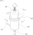
- FIG. 1 is a perspective view illustrating a gas collecting apparatus according of the present disclosure.
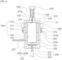
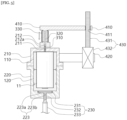
- FIG. 2 is a cross-sectional view illustrating a cross section A-A of FIG. 1 .
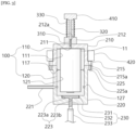
- FIG. 3 is a cross-sectional view illustrating a cross section B-B of FIG. 1 .
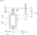
- FIG. 4 is a cross-sectional view illustrating an operation of a punching unit 300.
- FIG. 5 is a cross-sectional view illustrating separation of an inner jig 100.
- FIG. 6 is a perspective view illustrating the inner jig 100.
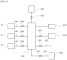
- FIG. 7 is a block diagram illustrating a gas collecting apparatus of the present disclosure.
- FIG. 8 is a block diagram illustrating a gas collecting method of the present disclosure.
- the battery to be a gas collecting target may be the cylindrical battery 11, and the inner jig 100 and the outer housing 200 may also be provided in a cylindrical shape.
- the punching needle 310 may be a rigid member having a sharp lower end.
- the punching needle 310 may be linearly movable in the upward and downward directions. When the punching needle 310 moves downward, the sharp lower end of the punching needle 310 may be inserted into the upper end of the battery 11 to form a perforated hole in the battery case.
- the lower end of the sealing cover 330 may be coupled to the upper end of the guide member 212, and more specifically, the lower end of the sealing cover 330 may be coupled to the upper end of the guide member 212 while covering the upper opening of the rod guide hole 212a.
- the sealing cover 330 may prevent gas inside and outside the outer housing 200 from being ventilated through the rod guide hole 212a.
- the punching driving unit 400 may include a moving member 410 to which an upper end of the sealing cover 330 and an upper end of the punching rod 320 are fixed, a support member 420 fixed to an outer circumferential surface of the outer housing 200, and a driving means 430 fixed to the support member 420 and configured to move the moving member 410 in the vertical direction.
- a space in which the lower end is opened is provided inside the upper housing 210, and a space in which the upper end of the lower housing 220 is opened is provided, and by the upper housing 210 and the lower housing 220 being coupled so that the lower end of the upper housing 210 and the upper end of the lower housing 220 contact each other, the two spaces may be formed as one closed space, and the inner jig 100 may be accommodated in the closed space.
- the upper housing 210 and the lower housing 220 may be provided in a cylindrical shape extending in the vertical direction.
- a ring-shaped first protrusion 215 protruding in the radial direction may be formed at the lower end of the outer circumferential surface of the upper housing 210
- a ring-shaped second protrusion 225 protruding in the radial direction may be formed at the upper end of the outer circumferential surface of the lower housing 220.
- the first protrusion 215 is provided with a plurality of first fixing holes 215a
- the second protrusion 225 is provided with a plurality of second fixing holes 225a
- a fixing member (not shown) may be simultaneously inserted into the first fixing hole 215a and the second fixing hole 225a to fix the coupling between the upper housing 210 and the lower housing 220.
- the fixing member may be a bolt provided with a screw thread, and a screw thread for screwing with the fixing member may be provided on an inner circumferential surface of the first fixing hole 215a or the second fixing hole 225a.
- the vertical length of the upper jig 110 may be longer than the vertical length of the inner space of the upper housing 210, and the vertical length of the lower jig 120 may be shorter than the vertical length of the inner space of the lower housing 220. Accordingly, the coupling portion between the upper jig 110 and the lower jig 120 may be located lower than the coupling portion between the upper housing 210 and the lower housing 220. Therefore, in the process of coupling the inner jig 100 to the outer housing 200, after the upper jig 110 and the lower jig 120 are simultaneously fixed to the lower housing 220, the upper housing 210 may be stably coupled to the upper end of the lower housing 220.
- a jig separator 230 for separating the lower jig 120 from the lower housing 220 may be provided at the lower end of the lower housing 220.
- the jig separator 230 may include a disk-shaped support plate 231 whose upper surface contacts the lower surface of the lower jig 120, a support bar 232 whose upper end is coupled to the lower surface of the support plate 231 and whose lower end protrudes to the outside of the lower housing 220 through a penetration hole 223 provided on the bottom surface of the lower housing 220, and a pneumatic cylinder 233 coupled to the lower end of the support bar 232 to move the support plate 231 and the support bar 232 in the vertical direction.
- the support plate 231 may be provided in a disk shape having a plane perpendicular to the vertical direction, and the support bar 232 may be provided in a bar shape extending in the vertical direction.
- the penetration hole 223 may include a first penetration hole 223a having an upper opening located inside the lower housing 220, and a second penetration hole 223b having a lower opening located outside the lower housing 220, wherein the lower opening of the first penetration hole 223a is connected to the upper opening of the second penetration hole 223b.
- the inner diameter of the first penetration hole 223a may be greater than or equal to the diameter of the support plate 231 so that the support plate 231 maybe completely buried in the bottom surface of the lower housing 220.
- the length of the first penetration hole 223a in the vertical direction may be greater than or equal to the thickness of the support plate 231.
- the dilution tank unit 520 and the second valve 502 are provided in plurality in pairs, and in each of the plurality of dilution tank units 520, the flow of gas with the manifold unit 500 is independently opened or closed by the plurality of second valves 502, and the gas collecting step may include
Landscapes
- Chemical & Material Sciences (AREA)
- Health & Medical Sciences (AREA)
- Life Sciences & Earth Sciences (AREA)
- Engineering & Computer Science (AREA)
- General Physics & Mathematics (AREA)
- Pathology (AREA)
- Immunology (AREA)
- Physics & Mathematics (AREA)
- Analytical Chemistry (AREA)
- Biochemistry (AREA)
- General Health & Medical Sciences (AREA)
- Food Science & Technology (AREA)
- Medicinal Chemistry (AREA)
- Combustion & Propulsion (AREA)
- Biomedical Technology (AREA)
- Molecular Biology (AREA)
- Manufacturing & Machinery (AREA)
- Chemical Kinetics & Catalysis (AREA)
- Electrochemistry (AREA)
- General Chemical & Material Sciences (AREA)
- Sampling And Sample Adjustment (AREA)
- Gas Exhaust Devices For Batteries (AREA)
Abstract
Description
- The present application claims the benefit of priority based on
Korean Patent Application No. 10-2022-0090849 filed on July 22, 2022 - The present disclosure relates to a gas collecting apparatus, and may be related to a gas collecting apparatus capable of collecting gas at an appropriate level of concentration for a battery having a case made of a rigid material of various specifications, in particular, a cylindrical battery.
- In general, a secondary battery is a battery which can be used repeatedly through a discharging process in which chemical energy is converted into electrical energy and a charging process in the opposite direction to the discharging process and which includes nickel-cadmium (Ni-Cd) batteries, nickel-metal hydride (Ni-MH) batteries, lithium-metal batteries, lithium-ion (Li-ion) batteries, and lithium-ion polymer batteries. Among these secondary batteries, lithium secondary batteries having high energy density and voltage, long cycle life, and a low self-discharge rate have been commercialized and widely used.
- Depending on the reaction within the lithium secondary battery, various types of gases such as hydrogen, oxygen, nitrogen, carbon monoxide, carbon dioxide, hydrocarbons of CnH2n-2 (n=2~5), CnH2n (n=2~5), CnH2n+2 (n=1~5), and other organic gas species, may be generated.
- In addition, the lithium secondary battery degrades while generating a large amount of gas due to electrolyte decomposition as repeated charging and discharging progresses, and this aspect appears differently depending on the design and use form of the battery. Therefore, it is essential to infer a deterioration mechanism of a battery by analyzing gas generated inside the battery during a battery development process.
- Therefore, it is very important to collect and accurately analyze the gas generated in the secondary battery. Various gases are generated during the operation of lithium ion batteries, and information on the composition and content of generated gases is useful for developing battery materials, optimizing battery manufacturing processes, and identifying causes of battery defects. To this end, it is important to develop a technology to collect the gas generated inside the secondary battery.
- As a method for collecting gas generated inside a secondary battery, a method in which, when a battery is accommodated in a diffusion chamber with an airtight space formed therein, an opening for gas discharge is formed in the battery case, and then the gas discharged through the opening is diffused into the diffusion chamber, the diffused gas is collected in a separate gas collecting container is used. For high-concentration gas collection, it may be most desirable that there is no clearance between the battery and the inner space of the diffusion chamber.
- Recently, batteries are used in a wide range of industrial fields, and depending on various battery application environments and conditions, performance required for batteries also varies, and batteries can be designed in various specifications.
- Conventionally, in order to design various batteries, it was difficult to newly manufacture or install each time a battery model is changed by individually using a diffusion chamber for gas collection according to the size of the battery. In addition, when there is no clearance between the battery and the inner space of the diffusion chamber, it was difficult to remove the battery from the diffusion chamber.
- In addition, the concentration of the gas delivered to an analyzer or stored in the gas collecting container varies greatly depending on the volume of the diffusion chamber, the size of the battery (material to be analyzed), and the amount of gas generated, which affects the analysis result. In order to solve this problem, a means for adjusting the concentration of the gas delivered to the analyzer or the gas stored in the gas collecting container to a concentration optimized for analysis is required.
- The present disclosure relates to a gas collecting apparatus, and is to provide a gas collecting apparatus capable of collecting gas at an appropriate level of concentration for a battery having a case made of a rigid material of various specifications, in particular, a cylindrical battery.
- Technical objects to be achieved by the present disclosure are not limited to the technical objects mentioned above, and other technical objects not mentioned will be clearly understood by those skilled in the art from the description below. Technical Solutions
- A gas collecting apparatus of the present disclosure may include
- an inner jig with a battery seating groove into which a battery is inserted formed on an upper surface;
- an outer housing accommodating the inner jig therein so that an outer circumferential surface of the inner jig adheres to its inner circumferential surface;
- a gas discharge pipe connected to the outer housing and configured to deliver gas generated from the battery to a gas collecting pipe or a gas analyzer provided outside the outer housing;
- a punching unit located at an upper end of the outer housing and forming a perforated hole for gas discharge on an upper surface of the battery; and
- a punching driving unit configured to provide a driving force for driving the punching unit in a vertical direction.
- A gas collecting apparatus of the present disclosure may have improved gas collection accuracy and convenience for an analyst by automating gas collection and high-concentration gas dilution.
- The gas collecting apparatus of the present disclosure maybe one in which batteries are easily installed, removed, or replaced when collecting gas.
- The gas collecting apparatus of the present disclosure may detect whether punching is completed by depth of a punching needle or an amount of pressure change to prevent a battery internal short circuit, thereby improving stability during gas collection.
- The gas collecting apparatus of the present disclosure maybe one in which the concentration of the gas to be collected may be easily adjusted according to a gas analysis target, situation, and conditions during gas collection. Specifically, the gas collecting apparatus of the present disclosure may selectively collect gas from high concentration to low concentration, and may measure the degree of dilution or concentration.
-
-
FIG. 1 is a perspective view illustrating a gas collecting apparatus according of the present disclosure. -
FIG. 2 is a cross-sectional view illustrating a cross section A-A ofFIG. 1 . -
FIG. 3 is a cross-sectional view illustrating a cross section B-B ofFIG. 1 . -
FIG. 4 is a cross-sectional view illustrating an operation of a punching unit. -
FIG. 5 is a cross-sectional view illustrating separation of an inner jig. -
FIG. 6 is a perspective view illustrating an inner jig. -
FIG. 7 is a block diagram illustrating a gas collecting apparatus of the present disclosure. -
FIG. 8 is a block diagram illustrating a gas collecting method of the present disclosure. - A gas collecting apparatus of the present disclosure may include
- an inner jig with a battery seating groove into which a battery is inserted formed on an upper surface;
- an outer housing accommodating the inner jig therein so that an outer circumferential surface of the inner jig adheres to its inner circumferential surface;
- a gas discharge pipe connected to the outer housing and configured to deliver gas generated from the battery to a gas collecting pipe or a gas analyzer provided outside the outer housing;
- a punching unit located at an upper end of the outer housing and forming a perforated hole for gas discharge on an upper surface of the battery; and
- a punching driving unit configured to provide a driving force for driving the punching unit in a vertical direction.
- In the gas collecting apparatus of the present disclosure, the punching unit may include a punching needle which is inserted inside the outer housing through a needle insertion hole provided at the upper end of the outer housing, a lower end of the punching needle perforating the upper surface of the battery to form the perforated hole on the upper surface of the battery, a punching rod configured to move in the vertical direction by the punching driving unit, an upper end of the punching needle being coupled to a lower end of the punching rod, and a sealing cover configured to surround an outer circumferential surface of the punching rod, a lower end of the sealing cover being coupled to the upper end of the outer housing.
- In the gas collecting apparatus of the present disclosure, the sealing cover may be provided as bellows extending or contracting in the vertical direction, an upper end of the sealing cover may be coupled to a moving member of the punching driving unit together with an upper end of the punching rod, and the lower end of the sealing cover may cover the needle insertion hole and be coupled to the upper end of the outer housing.
- In the gas collecting apparatus of the present disclosure, the punching driving unit may include a moving member to which an upper end of the sealing cover and an upper end of the punching rod are fixed, a support member fixed to an outer circumferential surface of the outer housing, and a driving means fixed to the support member and configured to move the moving member in the vertical direction.
- In the gas collecting apparatus of the present disclosure, the driving means may include a shaft extending in the vertical direction and provided with a screw thread on its outer circumferential surface, and a motor configured to rotate the shaft while being supported by the support member, wherein in the moving member, a shaft insertion hole into which the shaft is inserted is formed, and on an inner circumferential surface of the shaft insertion hole, a screw thread engaging with the screw thread of the shaft is formed.
- In the gas collecting apparatus of the present disclosure, the outer housing may include an upper housing in which an upper end of the inner jig is accommodated, and a lower housing in which a lower end of the inner jig is accommodated, wherein on an upper surface of the upper housing, the needle insertion hole is formed, and the punching unit is coupled to the upper surface of the upper housing while covering the needle insertion hole from an outer side of the upper housing.
- In the gas collecting apparatus of the present disclosure, the inner jig may include an upper jig provided with a battery insertion hole into which an upper end of the battery is inserted, and a lower jig provided with a battery insertion groove into which a lower end of the battery is inserted on an upper surface, wherein the battery insertion hole is formed to penetrate the upper jig in the vertical direction, an upper opening of the battery insertion hole faces the needle insertion hole in an inner side of the upper housing, and a lower opening of the battery insertion hole faces an inlet of the battery insertion groove.
- In the gas collecting apparatus of the present disclosure, the gas discharge pipe may be coupled to a side surface of the lower housing, in the upper jig, a first flow path configured to deliver gas discharged from an inside of the battery through the perforated hole and diffused inside the upper housing to the inside of the lower housing may be formed, and in the lower jig, a second flow path configured to deliver the gas delivered through the first flow path to the gas discharge pipe may be formed.
- In the gas collecting apparatus of the present disclosure, an upper surface of the upper jig may be spaced apart from a ceiling surface at a predetermined interval inside the upper housing, the upper jig and the lower jig may be provided in a column shape extending in the vertical direction, the first flow path may be formed as a groove extending from an upper end to a lower end of the upper jig on an outer surface of the upper jig, and the second flow path may be formed as a groove extending from an upper end of the lower jig to a height at which the gas discharge pipe is connected to the lower housing on an outer surface of the lower jig.
- In the gas collecting apparatus of the present disclosure, the upper jig and the lower jig maybe provided in a cylindrical shape extending in the vertical direction, and at a lower end of a side surface of the upper jig or the upper end of the lower jig, a first connection flow path provided as a ring-shaped groove along an outer circumferential surface may be formed, wherein a lower end of the first flow path and an upper end of the second flow path may be connected to the first connection flow path.
- In the gas collecting apparatus of the present disclosure, a second connection flow path provided as a ring-shaped groove along the outer circumferential surface may be formed in the lower jig, a lower end of the second flow path may be connected to the second connection flow path, and a height of the second connection flow path may be the same as the height at which the gas discharge pipe is connected to the lower housing.
- The gas collecting apparatus of the present disclosure may further include a pressure sensor configured to measure a pressure inside the outer housing, wherein the punching driving unit is operated based on a measured value of the pressure sensor.
- The gas collecting apparatus of the present disclosure may further include
- a manifold unit connected to the gas discharge pipe to receive the gas generated from the battery from the outer housing;
- a dilution tank unit connected to the manifold unit to dilute the gas delivered to the manifold unit;
- a vacuum pump unit connected to the manifold unit to form a vacuum in the dilution tank unit; and
- a gas delivering pipe connected to the manifold unit to deliver the gas to the gas collecting pipe or the gas collecting apparatus,
- wherein the pressure sensor is connected to the manifold unit.
- The gas collecting apparatus of the present disclosure may include
- a first valve provided in the gas discharge pipe to block or open a flow of gas flowing through the gas discharge pipe to the manifold unit;
- a second valve configured to block or open a flow path between the dilution tank unit and the manifold unit;
- a third valve configured to block or open a flow path between the vacuum pump unit and the manifold unit;
- a fourth valve provided in the gas delivering pipe to block or open a flow of gas flowing through the gas delivering pipe to the gas collecting pipe or the gas collecting apparatus;
- a gas exhaust pipe connected to the manifold unit to exhaust the gas delivered to the manifold unit to an outside; and
- a fifth valve provided in the gas exhaust pipe to block or open a flow of gas exhausted to the outside through the gas exhaust pipe.
- A gas collecting method using the gas collecting apparatus of the present disclosure may include
- a vacuum forming step of forming a vacuum inside the outer housing and the dilution tank through the vacuum pump unit;
- a perforated hole forming step of forming the perforated hole in the battery by the punching unit;
- a pressure change value calculating step of calculating a pressure change value through the measured value of the pressure sensor;
- a needle retracting step of retracting the needle when the pressure change value is greater than or equal to a set value; and
- a gas collecting step of opening the fourth valve and delivering gas to the gas collecting pipe or the gas analyzer.
- Hereinafter, embodiments according to the present disclosure will be described in detail with reference to the accompanying drawings. In this process, the size or shape of components shown in the drawings may be exaggerated for clarity and convenience of explanation. In addition, terms specifically defined in consideration of the configurations and operations of the present disclosure may vary according to the intentions or customs of users and operators. Definitions of these terms should be made based on the disclosures throughout this specification.
- In the description of the present disclosure, it should be noted that the orientation or positional relationship indicated by the terms such as "center", "upper", "lower", "left", "right", "vertical", "horizontal", "inner side", "outer side", "one surface", or "other surface" is based on the orientation or positional relationship shown in the drawing or the orientation or positional relationship normally arranged when using the product of the present disclosure, and it is intended only for explanation and brief description of the present disclosure, and is not to be construed as limiting the present disclosure because it does not suggest or imply that the device or element shown must necessarily be configured or operated in a specific orientation with a specific orientation.
-
FIG. 1 is a perspective view illustrating a gas collecting apparatus according of the present disclosure.FIG. 2 is a cross-sectional view illustrating a cross section A-A ofFIG. 1 .FIG. 3 is a cross-sectional view illustrating a cross section B-B ofFIG. 1 .FIG. 4 is a cross-sectional view illustrating an operation of apunching unit 300.FIG. 5 is a cross-sectional view illustrating separation of aninner jig 100.FIG. 6 is a perspective view illustrating theinner jig 100.FIG. 7 is a block diagram illustrating a gas collecting apparatus of the present disclosure.FIG. 8 is a block diagram illustrating a gas collecting method of the present disclosure. - Hereinafter, with reference to
FIGS. 1 to 8 , the gas collecting apparatus of the present disclosure will be described in detail. - The gas collecting apparatus of the present disclosure may collect gas generated from an electrolyte solution, an electrode, or the like inside a
battery 11. Specifically, when thebattery 11 is charged and discharged or a specific condition (temperature, etc.) is given to thebattery 11, various types of gases, such as hydrogen, oxygen, nitrogen, carbon monoxide, carbon dioxide, hydrocarbons of CnH2n-2 (n=2~5), CnH2n (n=2~5), CnH2n+2 (n=1~5), and other organic gas species may be generated according to reactions within thebattery 11. In order to quantitatively and qualitatively analyze such a gas, the gas collecting apparatus of the present disclosure may collect the gas. - In the gas collecting apparatus of the present disclosure, the
battery 11 to be a gas collecting target may be a cylindrical battery. More specifically, it may be a battery in which gas is generated inside the battery case by charging/discharging or applying specific conditions (temperature, shock, vibration, etc.). In the gas collecting apparatus of the present disclosure, a perforated hole may be formed by perforating one end of thebattery 11 in which gas is generated inside the battery case, and gas discharged through the perforated hole may be collected in the battery case. - As shown in
FIGS. 1 to 3 , the gas collecting apparatus of the present disclosure may include - the
inner jig 100 with thebattery 11 seating groove into which thebattery 11 is inserted formed on an upper surface; - an
outer housing 200 accommodating theinner jig 100 therein so that an outer circumferential surface of theinner jig 100 adheres to the inner circumferential surface of the outer housing; - a
gas discharge pipe 221 connected to theouter housing 200 and configured to deliver gas generated from thebattery 11 to agas collecting pipe 12 or agas analyzer 13 provided outside theouter housing 200; - the
punching unit 300 located at an upper end of theouter housing 200 and forming a perforated hole for gas discharge on an upper surface of thebattery 11; and - a
punching driving unit 400 configured to provide a driving force for driving thepunching unit 300 in a vertical direction. - The gas collecting apparatus of the present disclosure provides a plurality of
inner jigs 100 having different inner diameters for each type of battery forbattery 11 of various specifications, so that even if the specifications of thebattery 11 are different, the volume of a space in which gas is diffused within theouter housing 200 may be the same. - In the gas collecting apparatus of the present disclosure, since the
punching unit 300 configured to form the perforated hole in thebattery 11 is automatically operated through thepunching driving unit 400, precise and stable perforated hole formation may be possible. In the gas collecting apparatus of the present disclosure, the perforated hole may be formed by thepunching unit 300 at one end of thecylindrical battery 11 and gas discharged from thebattery 11 may be collected through the perforated hole. - As described above, in the gas collecting apparatus of the present disclosure, the battery to be a gas collecting target may be the
cylindrical battery 11, and theinner jig 100 and theouter housing 200 may also be provided in a cylindrical shape. - As shown in
FIGS. 1 to 3 , thepunching unit 300 may include a punchingneedle 310 which is inserted inside theouter housing 200 through aneedle insertion hole 211 provided at the upper end of theouter housing 200, a lower end of the punchingneedle 310 perforating the upper surface of thebattery 11 to form the perforated hole on the upper surface of thebattery 11, a punchingrod 320 configured to move in the vertical direction by thepunching driving unit 400, an upper end of the punchingneedle 310 being coupled to a lower end of the punchingrod 320, and a sealingcover 330 configured to surround an outer circumferential surface of the punchingrod 320, a lower end of the sealingcover 330 being coupled to the upper end of theouter housing 200. - The punching
needle 310 may be a rigid member having a sharp lower end. The punchingneedle 310 may be linearly movable in the upward and downward directions. When the punchingneedle 310 moves downward, the sharp lower end of the punchingneedle 310 may be inserted into the upper end of thebattery 11 to form a perforated hole in the battery case. - The punching
rod 320 may have a lower end coupled to the upper end of the punchingneedle 310 and move in the vertical direction together with the punchingneedle 310. The punchingrod 320 may be provided in a bar shape extending in the vertical direction. The punchingrod 320 may be made of a highly rigid chemical resistant material. - The sealing
cover 330 may be provided as bellows extending or contracting in the vertical direction, an upper end of the sealingcover 330 may be coupled to a movingmember 410 of thepunching driving unit 400 together with an upper end of the punchingrod 320, and the lower end of the sealingcover 330 may cover theneedle insertion hole 211 and be coupled to the upper end of theouter housing 200. For example, the punchingneedle 310 may be provided in a cylindrical shape with a pointed lower end, and the punchingrod 320 may be provided in a cylindrical shape having a larger diameter than the punchingneedle 310. - On the upper surface of the
outer housing 200, aneedle insertion hole 211 penetrating the ceiling surface of theouter housing 200 is formed, and the punchingneedle 310 may be inserted into theneedle insertion hole 211. The punchingneedle 310 may form a perforated hole by approaching the upper end of thebattery 11 located inside theouter housing 200 through theneedle insertion hole 211. - On the upper surface of the
outer housing 200, aguide member 212 configured to guide vertical movement of the punchingrod 320 may be provided. In theguide member 212, arod guide hole 212a is provided in the vertical direction of theguide member 212, and a punchingrod 320 may be inserted into therod guide hole 212a. The lower opening of therod guide hole 212a may face the upper opening of theneedle insertion hole 211. The outer diameter of the punchingrod 320 and the inner diameter of therod guide hole 212a may match. - The lower end of the sealing
cover 330 may be coupled to the upper end of theguide member 212, and more specifically, the lower end of the sealingcover 330 may be coupled to the upper end of theguide member 212 while covering the upper opening of therod guide hole 212a. The sealingcover 330 may prevent gas inside and outside theouter housing 200 from being ventilated through therod guide hole 212a. - As shown in
FIGS. 3 and4 , thepunching driving unit 400 may include a movingmember 410 to which an upper end of the sealingcover 330 and an upper end of the punchingrod 320 are fixed, asupport member 420 fixed to an outer circumferential surface of theouter housing 200, and a driving means 430 fixed to thesupport member 420 and configured to move the movingmember 410 in the vertical direction. - The moving
member 410 moves in the vertical direction through the driving force of the driving means, and more specifically, may transmit the driving force of the driving means 430 to the punchingneedle 310. The punchingneedle 310 may be fixed to the movingmember 410 through the punchingrod 320, and the punchingneedle 310 may move vertically along with the movingmember 410 by the movingmember 410 moving in the vertical direction. The movingmember 410 may be provided in a bar shape extending in a direction perpendicular to the vertical direction, wherein the punchingrod 320 and the upper end of the sealing cover may be coupled to one end of the movingmember 410, and the driving means 430 may be coupled to the other end. The movingmember 410 may be provided with a guide means (not shown) supported by theouter housing 200 and guiding the vertical movement of the movingmember 410. The movingmember 410 may move while sliding in the vertical direction while in contact with the guide means. - The
support member 420 may be fixed to theouter housing 200. Thesupport member 420 supports the driving means 430 and may prevent the driving means 430 from changing its relative location with respect to theouter housing 200. - As the separation distance of the moving
member 410 relative to thesupport member 420 in the vertical direction is changed by the driving means 430, the punching needle may approach or be separated from thebattery 11. - The driving means 430 may include a
shaft 431 extending in the vertical direction and provided with a screw thread on its outer circumferential surface, and amotor 432 configured to rotate theshaft 431 while being supported by the support member, wherein in the movingmember 410, ashaft insertion hole 411 into which theshaft 431 is inserted is formed, and on an inner circumferential surface of theshaft insertion hole 411, a screw thread engaging with the screw thread of theshaft 431 is formed. - The
shaft 431 may extend in the vertical direction and rotate in the vertical direction, which is a longitudinal direction, as a rotation axis direction. The relative position of theshaft 431 and thesupport member 420 may be constant. Since the screw thread of theshaft insertion hole 411 provided in the movingmember 410 is engaged with the screw thread of theshaft 431, when theshaft 431 rotates, the movingmember 410 may move in the vertical direction.. When theshaft 431 rotates, the movingmember 410 may be prevented from rotating together with theshaft 431 by the guide means. - The
motor 432 may provide a driving force for rotating theshaft 431. Since the gas collecting apparatus of the present disclosure converts rotational motion into linear motion when the punchingneedle 310 moves, precise manipulation may be possible. A decrease in the controllability of the insertion depth of the punchingneedle 310 may cause an accident by causing a short circuit of the electrode. The gas collecting apparatus of the present disclosure may be capable of stable operation by preventing accidents by precisely manipulating the punchingneedle 310. The gas collecting apparatus of the present disclosure may measure the vertical height of the punchingneedle 310 by sensing the amount of rotation of theshaft 431. For example, an encoder, a control unit, etc., may be connected to themotor 432 to measure and record the amount of rotation of theshaft 431. - As shown in
FIGS. 2 and3 , theouter housing 200 may include anupper housing 210 in which an upper end of theinner jig 100 is accommodated, and alower housing 220 in which a lower end of theinner jig 100 is accommodated, wherein on an upper surface of theupper housing 210, theneedle insertion hole 211 is formed, and thepunching unit 300 is coupled to the upper surface of theupper housing 210 while covering theneedle insertion hole 211 from an outer side of theupper housing 210. - A space in which the lower end is opened is provided inside the
upper housing 210, and a space in which the upper end of thelower housing 220 is opened is provided, and by theupper housing 210 and thelower housing 220 being coupled so that the lower end of theupper housing 210 and the upper end of thelower housing 220 contact each other, the two spaces may be formed as one closed space, and theinner jig 100 may be accommodated in the closed space. - The
upper housing 210 and thelower housing 220 may be provided in a cylindrical shape extending in the vertical direction. At this time, a ring-shapedfirst protrusion 215 protruding in the radial direction may be formed at the lower end of the outer circumferential surface of theupper housing 210, and a ring-shapedsecond protrusion 225 protruding in the radial direction may be formed at the upper end of the outer circumferential surface of thelower housing 220. - The lower side surface of the
first protrusion 215 and the upper side surface of thesecond protrusion 225 may come into close contact with each other to improve airtightness of a closed space formed by coupling theupper housing 210 and thelower housing 220. A sealing member such as an O-ring or a gasket may be inserted between thefirst protrusion 215 and thesecond protrusion 225 to further improve airtightness. - In order to fix the coupling between the
upper housing 210 and thelower housing 220, thefirst protrusion 215 is provided with a plurality of first fixingholes 215a, and thesecond protrusion 225 is provided with a plurality of second fixingholes 225a, and a fixing member (not shown) may be simultaneously inserted into thefirst fixing hole 215a and thesecond fixing hole 225a to fix the coupling between theupper housing 210 and thelower housing 220. The fixing member may be a bolt provided with a screw thread, and a screw thread for screwing with the fixing member may be provided on an inner circumferential surface of thefirst fixing hole 215a or thesecond fixing hole 225a. - As another embodiment for fixing the coupling between the
upper housing 210 and thelower housing 220, by providing a coupling means (not shown) for fixing the position of one of theupper housing 210 and thelower housing 220 and pressing the other unfixed one toward the fixed one, the coupling between theupper housing 210 and thelower housing 220 may be fixed. For example, thelower housing 220 may be fixed to a support (not shown), and a pneumatic actuator may be connected to the upper end of theupper housing 210 as the coupling means. The pneumatic actuator applies downward force to theupper housing 210, and the lower end of theupper housing 210 may be fixed in close contact with the upper end of thelower housing 220 by the force applied by the actuator. - The
upper housing 210 and thelower housing 220 may be made of stainless-steel material. - The
inner jig 100 may include anupper jig 110 provided with abattery insertion hole 111 into which an upper end of thebattery 11 is inserted, and alower jig 120 provided with abattery insertion groove 121 into which a lower end of thebattery 11 is inserted on an upper surface, wherein thebattery insertion hole 111 is formed to penetrate theupper jig 110 in the vertical direction, an upper opening of thebattery insertion hole 111 faces theneedle insertion hole 211 in an inner side of theupper housing 210, and a lower opening of thebattery insertion hole 111 faces an inlet of thebattery insertion groove 121. - The
upper jig 110 and thelower jig 120 may be provided in a cylindrical shape extending in the vertical direction. The outer diameters of theupper jig 110 and thelower jig 120 coincide with the inner diameters of theupper housing 210 and thelower housing 220, so that the outer circumferential surface of theupper jig 110 and the inner circumferential surface of theupper housing 210 may come into close contact with each other, and the outer circumferential surface of thelower jig 120 and the inner circumferential surface of thelower housing 220 may come into close contact with each other. - As shown in
FIGS. 2 to 4 , the vertical length of theupper jig 110 may be longer than the vertical length of the inner space of theupper housing 210, and the vertical length of thelower jig 120 may be shorter than the vertical length of the inner space of thelower housing 220. Accordingly, the coupling portion between theupper jig 110 and thelower jig 120 may be located lower than the coupling portion between theupper housing 210 and thelower housing 220. Therefore, in the process of coupling theinner jig 100 to theouter housing 200, after theupper jig 110 and thelower jig 120 are simultaneously fixed to thelower housing 220, theupper housing 210 may be stably coupled to the upper end of thelower housing 220. - Inside the
upper jig 110, abattery insertion hole 111 may be provided as a space for accommodating thebattery 11. Accordingly, the inner space of theupper jig 110 may be a space in which both the upper and lower ends are open. The upper opening of thebattery insertion hole 111 may allow the punchingneedle 310 to access the upper end of thebattery 11, and the lower opening of thebattery insertion hole 111 may be for merging the space formed by thebattery insertion hole 111 and the space formed by thebattery insertion groove 121 into one space. - Inside the
lower jig 120, abattery insertion groove 121 may be provided as a space for thebattery 11 to be accommodated. The opening of thebattery insertion groove 121 may be provided on the upper surface of thelower jig 120. Therefore, when theupper jig 110 and thelower jig 120 are coupled so that the lower end of theupper jig 110 and the upper end of thelower jig 120 face each other, the space of thebattery insertion hole 111 and the space of thebattery insertion groove 121 may be combined to form a single space for accommodating onebattery 11. - The
upper jig 110 and thelower jig 120 may be made of Teflon material. - A
jig separator 230 for separating thelower jig 120 from thelower housing 220 may be provided at the lower end of thelower housing 220. - As shown in
FIG. 5 , thejig separator 230 may include a disk-shapedsupport plate 231 whose upper surface contacts the lower surface of thelower jig 120, asupport bar 232 whose upper end is coupled to the lower surface of thesupport plate 231 and whose lower end protrudes to the outside of thelower housing 220 through apenetration hole 223 provided on the bottom surface of thelower housing 220, and apneumatic cylinder 233 coupled to the lower end of thesupport bar 232 to move thesupport plate 231 and thesupport bar 232 in the vertical direction. - The
support plate 231 may be provided in a disk shape having a plane perpendicular to the vertical direction, and thesupport bar 232 may be provided in a bar shape extending in the vertical direction. - The diameter of the
support plate 231 may be formed larger than the outer diameter of thesupport bar 232, so that thelower jig 120 may be raised upward by supporting the lower surface of thelower jig 120 with a larger area than thesupport bar 232 directly contacting thelower jig 120. - The
penetration hole 223 may include afirst penetration hole 223a having an upper opening located inside thelower housing 220, and asecond penetration hole 223b having a lower opening located outside thelower housing 220, wherein the lower opening of thefirst penetration hole 223a is connected to the upper opening of thesecond penetration hole 223b. The inner diameter of thefirst penetration hole 223a may be greater than or equal to the diameter of thesupport plate 231 so that thesupport plate 231 maybe completely buried in the bottom surface of thelower housing 220. The length of thefirst penetration hole 223a in the vertical direction may be greater than or equal to the thickness of thesupport plate 231. The inner diameter of thesecond penetration hole 223b may be formed to be the same as the outer diameter of thesupport bar 232, so that the outer circumferential surface of thesupport bar 232 is completely brought into close contact with the inner circumferential surface of thesecond penetration hole 223b to improve airtightness of the inner space of theouter housing 200. - As shown in
FIG. 6 , thegas discharge pipe 221 may be coupled to a side surface of thelower housing 220, in theupper jig 110, a first flow path 115 configured to deliver gas discharged from an inside of thebattery 11 through the perforated hole and diffused inside theupper housing 210 to the inside of thelower housing 220 may be formed, and in thelower jig 120, a second flow path 125 configured to deliver the gas delivered through the first flow path 115 to thegas discharge pipe 221 may be formed. - An upper surface of the
upper jig 110 may be spaced apart from a ceiling surface at a predetermined interval inside theupper housing 210, theupper jig 110 and thelower jig 120 may be provided in a column shape extending in the vertical direction, the first flow path 115 may be formed as a groove extending from an upper end to a lower end of theupper jig 110 on an outer surface of theupper jig 110, and the second flow path 125 may be formed as a groove extending from an upper end of thelower jig 120 to a height at which thegas discharge pipe 221 is connected to thelower housing 220 on an outer surface of thelower jig 120. - The
upper jig 110 and thelower jig 120 may be provided in a cylindrical shape extending in the vertical direction, and at a lower end of a side surface of theupper jig 110 or the upper end of thelower jig 120, a firstconnection flow path 117 provided as a ring-shaped groove along an outer circumferential surface may be formed, wherein a lower end of the first flow path 115 and an upper end of the second flow path 125 is connected to the firstconnection flow path 117. By providing the firstconnection flow path 117, even if theupper jig 110 and thelower jig 120 are not assembled so that the position of the lower end of the first flow path 115 completely matches the position of the upper end of the second flow path 125, gas in the first flow path 115 may flow to the second flow path 125 through the firstconnection flow path 117. - A second
connection flow path 127 provided as a ring-shaped groove along the outer circumferential surface may be formed in thelower jig 120, a lower end of the second flow path 125 may be connected to the secondconnection flow path 127, and a height of the secondconnection flow path 127 may be the same as the height at which thegas discharge pipe 221 is connected to thelower housing 220. By providing the secondconnection flow path 127, even if the position where thegas discharge pipe 221 is connected to thelower housing 220 does not face the second flow path 125, gas in the second flow path 125 may be delivered to thegas discharge pipe 221 through thesecond flow path 127. - The
gas discharge pipe 221 is provided as a tube, hose, or pipe, and may be used to deliver gas generated in thebattery 11 to thegas collecting pipe 12 or thegas analyzer 13. Thegas collecting pipe 12 may be a container in which an airtight sealed space is formed to store gas. Thegas analyzer 13 may be a device that receives gas and analyzes gas components and amounts. In other words, in order to qualitatively or quantitatively analyze the gas generated from thebattery 11, the gas collecting apparatus of the present disclosure may be for directly delivering the gas to thegas analyzer 13 or storing in thegas collecting pipe 12. - The gas collecting apparatus of the present disclosure may further include
apressure sensor 570 configured to measure a pressure inside theouter housing 200, wherein thepunching driving unit 400 is operated based on a measured value of thepressure sensor 570. - In the gas collecting apparatus of the present disclosure, the
battery 11 to be a gas collecting target may be in a state in which gas is generated therein. Therefore, when a perforated hole is formed in thebattery 11 by the punchingneedle 310, gas inside thebattery 11 diffuses into theouter housing 200 through the perforated hole, and the pressure in the inner space of theouter housing 200 may be increased. The gas collecting apparatus of the present disclosure may recognize the formation of the perforated hole by detecting this, and lift the punchingneedle 310 to separate the punchingneedle 310 from thebattery 11. - As shown in
FIG. 7 , the gas collecting apparatus of the present disclosure may further include - a
manifold unit 500 connected to thegas discharge pipe 221 to receive the gas generated from thebattery 11 from theouter housing 200; - a
dilution tank unit 520 connected to themanifold unit 500 to dilute the gas delivered to themanifold unit 500; - a
vacuum pump unit 530 connected to themanifold unit 500 to form a vacuum in thedilution tank unit 520; and - a
gas delivering pipe 540 connected to themanifold unit 500 to deliver the gas to thegas collecting pipe 12 or the gas collecting apparatus, wherein thepressure sensor 570 is connected to themanifold unit 500. - The
manifold unit 500 may connect the flow paths to which they are connected. - The
dilution tank unit 520 may be a container in which an airtight space is formed inside. Specifically, the gas collecting apparatus of the present disclosure may make the internal pressure of thegas collecting pipe 12 or the gas collecting apparatus lower than the inside of theouter housing 200 through thevacuum pump unit 530 to move the gas through gas diffusion through a pressure difference. At this time, by connecting thedilution tank unit 520 to the flow path connecting theouter housing 200 and thegas collecting pipe 12 or thegas analyzer 13 through themanifold unit 500, and expanding the space in which the gas diffuses when the gas moves through thedilution tank unit 520, high concentration gases can be diluted to a level suitable for gas analysis. - The gas collecting apparatus of the present disclosure may basically be capable of collecting high-concentration gas by filling the inner space of the
outer housing 200 through theinner jig 100, and may be adjustable to a gas concentration suitable for analysis through thedilution tank unit 520. In other words, the gas collecting apparatus of the present disclosure has a high degree of freedom in adjusting the gas concentration. - Before gas is discharged from the
outer housing 200, a vacuum may be previously formed inside thedilution tank unit 520 through a vacuum pump. - The
vacuum pump unit 530 may be used to form a negative pressure in thegas collecting pipe 12, thegas analyzer 13, or the dilution tank. - The
gas delivering pipe 540 is a pipe for forming a flow path, and may be configured to deliver gas between the manifold unit and thegas collecting pipe 12 or thegas analyzer 13. - As shown in
FIG. 7 , the gas collecting apparatus of the present disclosure may include - a
first valve 501 provided in thegas discharge pipe 221 to block or open a flow of gas flowing through thegas discharge pipe 221 to themanifold unit 500; - a
second valve 502 configured to block or open a flow path between thedilution tank unit 520 and themanifold unit 500; - a
third valve 503 configured to block or open a flow path between thevacuum pump unit 530 and themanifold unit 500; - a
fourth valve 504 provided in thegas delivering pipe 540 to block or open a flow of gas flowing through thegas delivering pipe 540 to thegas collecting pipe 12 or the gas collecting apparatus; - a
gas exhaust pipe 550 connected to themanifold unit 500 to exhaust the gas delivered to themanifold unit 500 to the outside; and - a
fifth valve 505 provided in thegas exhaust pipe 550 to block or open a flow of gas exhausted to the outside through thegas exhaust pipe 550. - The
first valve 501, thesecond valve 502, thethird valve 503, thefourth valve 504, and thefifth valve 505 may be electronic valves. The electronic valve is connected to the control unit and may be controlled through the control unit. The control unit may be a processor. Apressure sensor 570, amotor 432, an encoder, etc., are connected to the control unit, and based on the pressure value or the operating value of thepunching unit 300, etc., thefirst valve 501, thesecond valve 502, thethird valve 503, thefourth valve 504 and thefifth valve 505 may be operated. - The
gas exhaust pipe 550 has one end connected to themanifold unit 500 and the other end open to the atmosphere or connected to a scrubber, and may be used in a temporary high pressure relief or purge mode. In this case, thefifth valve 505 may be a relief valve. - As shown in
FIG. 8 , a gas collecting method of the present disclosure may include - a vacuum forming step of forming a vacuum inside the outer housing and the dilution tank through the vacuum pump unit;
- a perforated hole forming step of forming the perforated hole in the
battery 11 by thepunching unit 300; - a pressure change value calculating step of calculating a pressure change value through the measured value of the
pressure sensor 570; - a needle retracting step of retracting the needle when the pressure change value is greater than or equal to a set value; and
- a gas collecting step of opening the
fourth valve 504 and delivering gas to thegas collecting pipe 12 or thegas analyzer 13. - The gas collecting method of the present disclosure may further include a
battery 11 mounting step before the vacuum forming step. - In the
battery 11 mounting step, thebattery 11 may have an upper end inserted into theupper jig 110 and a lower end inserted into thelower jig 120 to be coupled with theinner jig 100. At this time, thebattery 11 may be coupled to theinner jig 100 so that the lower end of theupper jig 110 and the upper end of thelower jig 120 come into close contact. - In the
battery 11 mounting step, theupper housing 210 and thelower housing 220 may be respectively covered on the upper end and lower end of theinner jig 100 coupled with thebattery 11, respectively, and theupper housing 210 and thelower housing 220 may be coupled to each other so that the lower end of theupper housing 210 and the upper end of theupper housing 210 come into close contact with each other, so that theinner jig 100 may be accommodated inside theouter housing 200. - In the vacuum forming step, the vacuum may be formed by operating the
vacuum pump unit 530 while thefirst valve 501, thesecond valve 502, and thethird valve 503 are open. Thefourth valve 504 is also opened in the vacuum forming step, so that a vacuum may be formed in the gas collecting space provided in thegas collecting pipe 12 or thegas analyzer 13 as well. Thefifth valve 505 may be closed. - In the perforated hole forming step, the
punching driving unit 400 may lower the punchingneedle 310 to form a perforated hole in thebattery 11. Here, thesecond valve 502 and thethird valve 503 maybe closed. - In the pressure change value calculating step, the control unit may receive a pressure measured value from the
pressure sensor 570 and calculate the pressure change value over time. - In the gas collecting step, the
fourth valve 504 is opened, and the collected gas may be diluted by opening thesecond valve 502 if necessary. - More specifically, in the gas collecting apparatus of the present disclosure, the
dilution tank unit 520 and thesecond valve 502 are provided in plurality in pairs, and in each of the plurality ofdilution tank units 520, the flow of gas with themanifold unit 500 is independently opened or closed by the plurality ofsecond valves 502, and the gas collecting step may include - a first collecting step of opening the
fourth valve 504 in a state in which all of the plurality ofsecond valves 502 are closed, - a first dilution step of, if the measured value of the
pressure sensor 570 is less than or equal to the set pressure value after a first set time, completing the collection by determining as a normal concentration, and if greater than or equal to the set pressure value, opening some or all of the plurality ofsecond valves 502 by determining as a high concentration, - a second dilution step of, if the measured value of the
pressure sensor 570 is less than or equal to the set pressure value after a second set time, completing the collection by determining as a normal concentration, and if greater than or equal to the set pressure value, forming a vacuum by opening thethird valve 503 in a state in which thefourth valve 504 is closed together with some of the plurality ofsecond valves 502 opened in the first dilution step by determining as a high concentration, and - a second collecting step of closing the
third valve 503 and opening the fourth valve and some or all of the plurality ofsecond valves 502 closed in the second dilution step. - The first set time and the second set time may be determined in consideration of a gas diffusion rate, and the set pressure may be determined by specifications of the gas analyzer that analyzes the collected gas.
- In the first dilution step, the second dilution step, and the second collecting step, control of selective opening or closing of the plurality of
second valves 502 may be determined in consideration of the capacity of thedilution tank 520, the measured value of the pressure sensor, and the like. - After the gas collecting step, a purge step and a separation step may be further included.
- In the purge step, the inside of the
outer housing 200 may be purged by injecting a purge gas into themanifold unit 500 in a state where thefirst valve 501 and thefifth valve 505 are open. - In the separation step, after the
upper housing 210 and theupper jig 110 are separated from thebattery 11, thelower jig 120 may be discharged from thelower housing 220 by operating thejig separator 230. - Although embodiments according to the present disclosure have been described above, they are only illustrative and those skilled in the art will understand that various modifications and embodiments of equivalent range are possible therefrom. Therefore, the true technical protection scope of the present disclosure should be defined by the following claims.
- 11...Battery, 12...Gas collecting pipe 13...Gas analyzer, 100...Inner jig, 110...Upper jig, 111...Battery insertion hole, 115...First flow path, 117...First connection flow path, 120...Lower jig, 121...Battery insertion groove, 125...Second flow path, 127...Second connection flow path, 200...Outer housing, 210...Upper housing, 211...Needle insertion hole, 212...Guide member, 212a...Rod guide hole, 215...First protrusion, 215a...First fixing hole, 220...Lower housing, 221...Gas discharge pipe, 223...Penetration hole, 223a...First penetration hole, 223b...Second penetration hole, 225...Second protrusion, 225a...Second fixing hole, 230...Jig separator, 231...Support plate, 232...Support bar, 233...Pneumatic cylinder, 300...Punching unit, 310...Punching needle, 320...Punching rod, 330...Sealing cover, 400...Punching driving unit, 410...Moving member, 411...Shaft insertion hole, 420...Support member, 430...Driving means, 431...Shaft, 432...Motor, 500...Manifold unit, 501...First valve, 502...Second valve, 503...Third valve, 504...Fourth valve, 505...Fifth valve, 520...Dilution tank unit, 530...Vacuum pump unit, 540...Gas delivering pipe, 550...Gas exhaust pipe, 570...Pressure sensor
- A gas collecting apparatus of the present disclosure may have improved gas collection accuracy and convenience for the analyst by automating gas collection and high-concentration gas dilution.
- The gas collecting apparatus of the present disclosure may be one in which batteries are easily installed, removed, or replaced when collecting gas.
- The gas collecting apparatus of the present disclosure may detect whether punching is completed by the depth of the punching needle or the amount of pressure change to prevent a battery internal short circuit, thereby improving stability during gas collection.
- The gas collecting apparatus of the present disclosure may be one in which the concentration of the gas to be collected may be easily adjusted according to the gas analysis target, situation, and conditions during gas collection. Specifically, The gas collecting apparatus of the present disclosure may selectively collect gas from high concentration to low concentration, and may measure the degree of dilution or concentration.
Claims (15)
- A gas collecting apparatus comprising:an inner jig with a battery seating groove into which a battery is inserted formed on an upper surface;an outer housing accommodating the inner jig therein so that an outer circumferential surface of the inner jig adheres to its inner circumferential surface;a gas discharge pipe connected to the outer housing and configured to deliver gas generated from the battery to a gas collecting pipe or a gas analyzer provided outside the outer housing;a punching unit located at an upper end of the outer housing and forming a perforated hole for gas discharge on an upper surface of the battery; anda punching driving unit configured to provide a driving force for driving the punching unit in a vertical direction.
- The gas collecting apparatus of claim 1, wherein the punching unit comprises:a punching needle which is inserted inside the outer housing through a needle insertion hole provided at the upper end of the outer housing, a lower end of the punching needle perforating the upper surface of the battery to form the perforated hole on the upper surface of the battery;a punching rod configured to move in the vertical direction by the punching driving unit, an upper end of the punching needle being coupled to a lower end of the punching rod; anda sealing cover configured to surround an outer circumferential surface of the punching rod, a lower end of the sealing cover being coupled to the upper end of the outer housing.
- The gas collecting apparatus of claim 2, wherein the sealing cover is provided as bellows extending or contracting in the vertical direction,an upper end of the sealing cover is coupled to a moving member of the punching driving unit together with an upper end of the punching rod, andthe lower end of the sealing cover covers the needle insertion hole and is coupled to the upper end of the outer housing.
- The gas collecting apparatus of claim 2, wherein the punching driving unit comprises:a moving member to which an upper end of the sealing cover and an upper end of the punching rod are fixed;a support member fixed to an outer circumferential surface of the outer housing; anda driving means fixed to the support member and configured to move the moving member in the vertical direction.
- The gas collecting apparatus of claim 4, wherein the driving means comprises:a shaft extending in the vertical direction and provided with a screw thread on its outer circumferential surface; anda motor configured to rotate the shaft while being supported by the support member, andwherein in the moving member, a shaft insertion hole into which the shaft is inserted is formed, andon an inner circumferential surface of the shaft insertion hole, a screw thread engaging with the screw thread of the shaft is formed.
- The gas collecting apparatus of claim 2, wherein the outer housing comprises:an upper housing in which an upper end of the inner jig is accommodated; anda lower housing in which a lower end of the inner jig is accommodated, andwherein on an upper surface of the upper housing, the needle insertion hole is formed, andthe punching unit is coupled to the upper surface of the upper housing while covering the needle insertion hole from an outer side of the upper housing.
- The gas collecting apparatus of claim 6, wherein the inner jig comprises:an upper jig provided with a battery insertion hole into which an upper end of the battery is inserted; anda lower jig provided with a battery insertion groove into which a lower end of the battery is inserted on an upper surface, andwherein the battery insertion hole is formed to penetrate the upper jig in the vertical direction,an upper opening of the battery insertion hole faces the needle insertion hole in an inner side of the upper housing, anda lower opening of the battery insertion hole faces an inlet of the battery insertion groove.
- The gas collecting apparatus of claim 7, wherein the gas discharge pipe is coupled to a side surface of the lower housing,in the upper jig, a first flow path configured to deliver gas discharged from an inside of the battery through the perforated hole and diffused inside the upper housing to the inside of the lower housing is formed, andin the lower jig, a second flow path configured to deliver the gas delivered through the first flow path to the gas discharge pipe is formed.
- The gas collecting apparatus of claim 8, wherein an upper surface of the upper jig is spaced apart from a ceiling surface at a predetermined interval inside the upper housing,the upper jig and the lower jig are provided in a column shape extending in the vertical direction,the first flow path is formed as a groove extending from an upper end to a lower end of the upper jig on an outer surface of the upper jig, andthe second flow path is formed as a groove extending from an upper end of the lower jig to a height at which the gas discharge pipe is connected to the lower housing on an outer surface of the lower jig.
- The gas collecting apparatus of claim 9, wherein the upper jig and the lower jig are provided in a cylindrical shape extending in the vertical direction,at a lower end of a side surface of the upper jig or the upper end of the lower jig, a first connection flow path provided as a ring-shaped groove along an outer circumferential surface is formed, anda lower end of the first flow path and an upper end of the second flow path are connected to the first connection flow path.
- The gas collecting apparatus of claim 10, wherein a second connection flow path provided as a ring-shaped groove along the outer circumferential surface is formed in the lower jig,a lower end of the second flow path is connected to the second connection flow path, anda height of the second connection flow path is the same as the height at which the gas discharge pipe is connected to the lower housing.
- The gas collecting apparatus of claim 1, further comprising:a pressure sensor configured to measure a pressure inside the outer housing,wherein the punching driving unit is operated based on a measured value of the pressure sensor.
- The gas collecting apparatus of claim 12, further comprising:a manifold unit connected to the gas discharge pipe to receive the gas generated from the battery from the outer housing;a dilution tank unit connected to the manifold unit to dilute the gas delivered to the manifold unit;a vacuum pump unit connected to the manifold unit to form a vacuum in the dilution tank unit; anda gas delivering pipe connected to the manifold unit to deliver the gas to the gas collecting pipe or the gas collecting apparatus,wherein the pressure sensor is connected to the manifold unit.
- The gas collecting apparatus of claim 13, comprising:a first valve provided in the gas discharge pipe to block or open a flow of gas flowing through the gas discharge pipe to the manifold unit;a second valve configured to block or open a flow path between the dilution tank unit and the manifold unit;a third valve configured to block or open a flow path between the vacuum pump unit and the manifold unit;a fourth valve provided in the gas delivering pipe to block or open a flow of gas flowing through the gas delivering pipe to the gas collecting pipe or the gas collecting apparatus;a gas exhaust pipe connected to the manifold unit to exhaust the gas delivered to the manifold unit to an outside; anda fifth valve provided in the gas exhaust pipe to block or open a flow of gas exhausted to the outside through the gas exhaust pipe.
- A gas collecting method using the gas collecting apparatus of claim 14, comprising:a vacuum forming step of forming a vacuum inside the outer housing and the dilution tank through the vacuum pump unit;a perforated hole forming step of forming the perforated hole in the battery by the punching unit;a pressure change value calculating step of calculating a pressure change value through the measured value of the pressure sensor;a needle retracting step of retracting the needle when the pressure change value is greater than or equal to a set value; anda gas collecting step of opening the fourth valve and delivering gas to the gas collecting pipe or the gas analyzer.
Applications Claiming Priority (2)
| Application Number | Priority Date | Filing Date | Title |
|---|---|---|---|
| KR1020220090849A KR20240013382A (en) | 2022-07-22 | 2022-07-22 | Apparatus for collecting gas |
| PCT/KR2023/010359 WO2024019504A1 (en) | 2022-07-22 | 2023-07-19 | Gas collection device |
Publications (3)
| Publication Number | Publication Date |
|---|---|
| EP4397953A1 true EP4397953A1 (en) | 2024-07-10 |
| EP4397953A4 EP4397953A4 (en) | 2025-01-22 |
| EP4397953B1 EP4397953B1 (en) | 2026-03-11 |
Family
ID=89618280
Family Applications (1)
| Application Number | Title | Priority Date | Filing Date |
|---|---|---|---|
| EP23843350.2A Active EP4397953B1 (en) | 2022-07-22 | 2023-07-19 | Gas collection device |
Country Status (5)
| Country | Link |
|---|---|
| EP (1) | EP4397953B1 (en) |
| JP (1) | JP7739612B2 (en) |
| KR (1) | KR20240013382A (en) |
| CN (1) | CN118541595A (en) |
| WO (1) | WO2024019504A1 (en) |
Cited By (2)
| Publication number | Priority date | Publication date | Assignee | Title |
|---|---|---|---|---|
| EP4414683A4 (en) * | 2022-07-28 | 2025-03-05 | LG Energy Solution, Ltd. | GAS COLLECTION DEVICE |
| WO2026071963A1 (en) * | 2024-09-30 | 2026-04-02 | Traton Ab | An arrangement and a method for collecting gas from a battery cell |
Family Cites Families (14)
| Publication number | Priority date | Publication date | Assignee | Title |
|---|---|---|---|---|
| JPS5748635A (en) * | 1980-09-08 | 1982-03-20 | Toshiba Corp | Gas capturing device for battery |
| JPH041550A (en) * | 1990-04-18 | 1992-01-07 | Mitsubishi Electric Corp | Sampling device ad method for semiconductor device sealing gas analysis |
| JP2011192523A (en) * | 2010-03-15 | 2011-09-29 | Toyota Motor Corp | Manufacturing method and degassing device of secondary battery |
| KR101590395B1 (en) * | 2015-05-26 | 2016-02-18 | 이현철 | Gas extraction system of medium and large secondary battery |
| JP2017009539A (en) * | 2015-06-25 | 2017-01-12 | 株式会社住化分析センター | Gas analysis device and gas analysis method |
| JP6730056B2 (en) * | 2016-03-29 | 2020-07-29 | 株式会社コベルコ科研 | Method and apparatus for analyzing generated gas of power storage device |
| US11374271B2 (en) * | 2017-10-26 | 2022-06-28 | Lg Energy Solution, Ltd. | Apparatus, system, and method for collecting gas generated in secondary battery |
| CN109935919B (en) * | 2017-12-19 | 2022-05-17 | 中国科学院物理研究所 | A gas collection device for batteries |
| KR102145107B1 (en) * | 2018-04-12 | 2020-08-14 | 주식회사 엘지화학 | Apparatus for collecting inner gas in secondary electric cell and method thereof |
| KR102133646B1 (en) * | 2018-05-21 | 2020-07-13 | 주식회사 엘지화학 | Apparatus for collecting inner gas in secondary electric cell and method thereof for charging and discharging |
| KR20200004745A (en) * | 2018-07-04 | 2020-01-14 | 주식회사 엘지화학 | An automated apparatus for collecting gas generated inside secondary battery and a method thereof |
| KR102455848B1 (en) * | 2018-12-03 | 2022-10-18 | 주식회사 엘지에너지솔루션 | Jig for measuring internal pressure of cylindrical battery cell |
| KR20210125283A (en) * | 2020-04-08 | 2021-10-18 | (주)이손 | Apparatus for analyzing real gas in secondary battery |
| KR102495710B1 (en) | 2020-12-23 | 2023-02-06 | 주식회사 디아이티그린 | means for spraying absorbable active powders on non-woven web in air filter manufacturing apparatus |
-
2022
- 2022-07-22 KR KR1020220090849A patent/KR20240013382A/en active Pending
-
2023
- 2023-07-19 EP EP23843350.2A patent/EP4397953B1/en active Active
- 2023-07-19 WO PCT/KR2023/010359 patent/WO2024019504A1/en not_active Ceased
- 2023-07-19 JP JP2024523764A patent/JP7739612B2/en active Active
- 2023-07-19 CN CN202380018489.2A patent/CN118541595A/en active Pending
Cited By (2)
| Publication number | Priority date | Publication date | Assignee | Title |
|---|---|---|---|---|
| EP4414683A4 (en) * | 2022-07-28 | 2025-03-05 | LG Energy Solution, Ltd. | GAS COLLECTION DEVICE |
| WO2026071963A1 (en) * | 2024-09-30 | 2026-04-02 | Traton Ab | An arrangement and a method for collecting gas from a battery cell |
Also Published As
| Publication number | Publication date |
|---|---|
| JP2024542961A (en) | 2024-11-19 |
| EP4397953B1 (en) | 2026-03-11 |
| KR20240013382A (en) | 2024-01-30 |
| WO2024019504A1 (en) | 2024-01-25 |
| CN118541595A (en) | 2024-08-23 |
| EP4397953A4 (en) | 2025-01-22 |
| JP7739612B2 (en) | 2025-09-16 |
Similar Documents
| Publication | Publication Date | Title |
|---|---|---|
| EP3696902B1 (en) | Apparatus and method for collecting gas | |
| EP4397953B1 (en) | Gas collection device | |
| EP3809512B1 (en) | Secondary-battery internal gas collecting apparatus | |
| KR102397315B1 (en) | Apparatus for collecting secondary cell internal gas | |
| KR20210103764A (en) | Apparatus for collecting cell internal gas | |
| US20240204350A1 (en) | Gas collection device | |
| KR20230000625A (en) | Apparatus for collecting gas | |
| EP4414683B1 (en) | Gas collection device | |
| JP7782072B2 (en) | Gas analyzers | |
| EP4432421A1 (en) | Gas collection device | |
| EP4685452A1 (en) | Gas collection device | |
| JP2026514597A (en) | Gas collection device | |
| KR102837157B1 (en) | Apparatus for collecting gas | |
| US20260133099A1 (en) | Gas Collection Device | |
| JP2026513398A (en) | Gas collection device | |
| EP4650747A1 (en) | Gas collection device and gas analysis device using same |
Legal Events
| Date | Code | Title | Description |
|---|---|---|---|
| STAA | Information on the status of an ep patent application or granted ep patent |
Free format text: STATUS: THE INTERNATIONAL PUBLICATION HAS BEEN MADE |
|
| PUAI | Public reference made under article 153(3) epc to a published international application that has entered the european phase |
Free format text: ORIGINAL CODE: 0009012 |
|
| STAA | Information on the status of an ep patent application or granted ep patent |
Free format text: STATUS: REQUEST FOR EXAMINATION WAS MADE |
|
| 17P | Request for examination filed |
Effective date: 20240405 |
|
| AK | Designated contracting states |
Kind code of ref document: A1 Designated state(s): AL AT BE BG CH CY CZ DE DK EE ES FI FR GB GR HR HU IE IS IT LI LT LU LV MC ME MK MT NL NO PL PT RO RS SE SI SK SM TR |
|
| A4 | Supplementary search report drawn up and despatched |
Effective date: 20250102 |
|
| RIC1 | Information provided on ipc code assigned before grant |
Ipc: H01M 10/04 20060101ALI20241218BHEP Ipc: G01N 33/00 20060101ALI20241218BHEP Ipc: G01N 1/22 20060101AFI20241218BHEP |
|
| GRAP | Despatch of communication of intention to grant a patent |
Free format text: ORIGINAL CODE: EPIDOSNIGR1 |
|
| STAA | Information on the status of an ep patent application or granted ep patent |
Free format text: STATUS: GRANT OF PATENT IS INTENDED |
|
| DAV | Request for validation of the european patent (deleted) | ||
| DAX | Request for extension of the european patent (deleted) | ||
| INTG | Intention to grant announced |
Effective date: 20251009 |
|
| GRAS | Grant fee paid |
Free format text: ORIGINAL CODE: EPIDOSNIGR3 |
|
| GRAA | (expected) grant |
Free format text: ORIGINAL CODE: 0009210 |
|
| STAA | Information on the status of an ep patent application or granted ep patent |
Free format text: STATUS: THE PATENT HAS BEEN GRANTED |
|
| AK | Designated contracting states |
Kind code of ref document: B1 Designated state(s): AL AT BE BG CH CY CZ DE DK EE ES FI FR GB GR HR HU IE IS IT LI LT LU LV MC ME MK MT NL NO PL PT RO RS SE SI SK SM TR |
|
| REG | Reference to a national code |
Ref country code: CH Ref legal event code: F10 Free format text: ST27 STATUS EVENT CODE: U-0-0-F10-F00 (AS PROVIDED BY THE NATIONAL OFFICE) Effective date: 20260311 Ref country code: GB Ref legal event code: FG4D |
|
| P01 | Opt-out of the competence of the unified patent court (upc) registered |
Free format text: CASE NUMBER: UPC_APP_0005052_4397953/2026 Effective date: 20260211 |
|
| REG | Reference to a national code |
Ref country code: DE Ref legal event code: R096 Ref document number: 602023013532 Country of ref document: DE |
|
| REG | Reference to a national code |
Ref country code: IE Ref legal event code: FG4D |