EP4397895A1 - Pressure regulating valve - Google Patents
Pressure regulating valve Download PDFInfo
- Publication number
- EP4397895A1 EP4397895A1 EP22864069.4A EP22864069A EP4397895A1 EP 4397895 A1 EP4397895 A1 EP 4397895A1 EP 22864069 A EP22864069 A EP 22864069A EP 4397895 A1 EP4397895 A1 EP 4397895A1
- Authority
- EP
- European Patent Office
- Prior art keywords
- valve
- pressure
- regulating valve
- pressure sensitive
- pressure regulating
- Prior art date
- Legal status (The legal status is an assumption and is not a legal conclusion. Google has not performed a legal analysis and makes no representation as to the accuracy of the status listed.)
- Granted
Links
Images




Classifications
-
- F—MECHANICAL ENGINEERING; LIGHTING; HEATING; WEAPONS; BLASTING
- F16—ENGINEERING ELEMENTS AND UNITS; GENERAL MEASURES FOR PRODUCING AND MAINTAINING EFFECTIVE FUNCTIONING OF MACHINES OR INSTALLATIONS; THERMAL INSULATION IN GENERAL
- F16K—VALVES; TAPS; COCKS; ACTUATING-FLOATS; DEVICES FOR VENTING OR AERATING
- F16K31/00—Actuating devices; Operating means; Releasing devices
- F16K31/02—Actuating devices; Operating means; Releasing devices electric; magnetic
- F16K31/04—Actuating devices; Operating means; Releasing devices electric; magnetic using a motor
- F16K31/047—Actuating devices; Operating means; Releasing devices electric; magnetic using a motor characterised by mechanical means between the motor and the valve, e.g. lost motion means reducing backlash, clutches, brakes or return means
-
- F—MECHANICAL ENGINEERING; LIGHTING; HEATING; WEAPONS; BLASTING
- F16—ENGINEERING ELEMENTS AND UNITS; GENERAL MEASURES FOR PRODUCING AND MAINTAINING EFFECTIVE FUNCTIONING OF MACHINES OR INSTALLATIONS; THERMAL INSULATION IN GENERAL
- F16K—VALVES; TAPS; COCKS; ACTUATING-FLOATS; DEVICES FOR VENTING OR AERATING
- F16K31/00—Actuating devices; Operating means; Releasing devices
- F16K31/44—Mechanical actuating means
- F16K31/50—Mechanical actuating means with screw-spindle or internally threaded actuating means
-
- F—MECHANICAL ENGINEERING; LIGHTING; HEATING; WEAPONS; BLASTING
- F16—ENGINEERING ELEMENTS AND UNITS; GENERAL MEASURES FOR PRODUCING AND MAINTAINING EFFECTIVE FUNCTIONING OF MACHINES OR INSTALLATIONS; THERMAL INSULATION IN GENERAL
- F16K—VALVES; TAPS; COCKS; ACTUATING-FLOATS; DEVICES FOR VENTING OR AERATING
- F16K31/00—Actuating devices; Operating means; Releasing devices
- F16K31/44—Mechanical actuating means
- F16K31/53—Mechanical actuating means with toothed gearing
-
- F—MECHANICAL ENGINEERING; LIGHTING; HEATING; WEAPONS; BLASTING
- F16—ENGINEERING ELEMENTS AND UNITS; GENERAL MEASURES FOR PRODUCING AND MAINTAINING EFFECTIVE FUNCTIONING OF MACHINES OR INSTALLATIONS; THERMAL INSULATION IN GENERAL
- F16K—VALVES; TAPS; COCKS; ACTUATING-FLOATS; DEVICES FOR VENTING OR AERATING
- F16K41/00—Spindle sealings
- F16K41/10—Spindle sealings with diaphragm, e.g. shaped as bellows or tube
-
- F—MECHANICAL ENGINEERING; LIGHTING; HEATING; WEAPONS; BLASTING
- F25—REFRIGERATION OR COOLING; COMBINED HEATING AND REFRIGERATION SYSTEMS; HEAT PUMP SYSTEMS; MANUFACTURE OR STORAGE OF ICE; LIQUEFACTION SOLIDIFICATION OF GASES
- F25B—REFRIGERATION MACHINES, PLANTS OR SYSTEMS; COMBINED HEATING AND REFRIGERATION SYSTEMS; HEAT PUMP SYSTEMS
- F25B41/00—Fluid-circulation arrangements
- F25B41/20—Disposition of valves, e.g. of on-off valves or flow control valves
- F25B41/22—Disposition of valves, e.g. of on-off valves or flow control valves between evaporator and compressor
-
- G—PHYSICS
- G05—CONTROLLING; REGULATING
- G05D—SYSTEMS FOR CONTROLLING OR REGULATING NON-ELECTRIC VARIABLES
- G05D16/00—Control of fluid pressure
- G05D16/20—Control of fluid pressure characterised by the use of electric means
- G05D16/2086—Control of fluid pressure characterised by the use of electric means without direct action of electric energy on the controlling means
Definitions
- the present invention relates to a pressure regulating valve which is used in a refrigeration cycle system, and more particularly to an evaporating pressure regulating valve which is provided with a pressure sensitive bellows.
- a pressure regulating valve is a pressure regulating valve including a vale main body having a valve chamber which is communicated with an inflow passage introducing a refrigerant and an outflow passage discharging the refrigerant, a valve body changing a flow rate of the refrigerant by advancing and retreating with respect to a valve seat between a valve-closed state in which the valve body is seated on the valve seat formed within the valve chamber and a valve-opened state in which the valve body is spaced apart from the valve seat, a pressure sensitive member allowing an advancing and retracting movement of the valve body by biasing the valve body toward the valve seat and expanding and contracting according to a pressure which the valve body is applied from the refrigerant flowing into from the inflow passage, and an adjustment means which adjusts a biasing force applied to the valve body of the pressure sensitive member, wherein an actuator driving the adjustment means is provided.
- the adjustment means preferably has a stopper member which stops the movement of the adjustment member by the actuator and can be set as a starting point when setting the biasing force of the pressure sensitive member. This is performed for allowing the valve opening characteristic (the biasing force of the pressure sensitive member), that is, the evaporating pressure (temperature) of the evaporator to be accurately setting changed.
- the stepping motor is used as the actuator is exemplified and is concretely described as follows.
- the upper lid 27 closing the upper portion of the valve chamber 13 is provided with an upper lid main body 27a which is fixed by being screwed into the upper surface opening 12a of the valve main body 12, and a flange portion 27b which expands horizontally outward from an upper surface portion of the upper lid main body 27a and comes into contact with the upper surface of the valve main body 12, and is a cup-shaped member having one end opened and other end bottomed which has a connection member accommodating hole 27c receiving the connection member 28 in an upper surface side of the upper lid main body 27a.
- the guide shaft portion 26 of the adjustment member 24 passes through the bottom plate portion 27d of the upper lid main body 27a from the upper portion of the valve chamber 13, and an upper end portion thereof is inserted into the small-diameter hole 28b through the stopper configuration space S.
- the stopper member 29 is installed in an intermediate portion (a portion extending into the stopper configuration space S) of the guide shaft portion 26.
- the stopper member 29 is a ring member which is fixed to the guide shaft portion 26 so as to protrude to a periphery horizontally (like a flange) from an outer peripheral surface of the guide shaft portion 26 and has a flat C shape.
- a tubular bearing member 34 is fitted and inserted into the upper portion of the connection member 28, and is fixed to the connection member 28 by caulking.
- the output gear 53 is slidably in contact with an upper surface of the bearing member 34.
- an upper portion of a stepped cylindrical output shaft 58 is pressed into the center of a bottom portion of the output gear 53, and a lower portion of the output shaft 58 is rotatably inserted into an insertion hole 34a which is formed in an upper surface portion of the center portion of the bearing member 34.
- a lower end portion of the shaft 38 is fitted to the upper portion of the output shaft 58 so as to be relatively rotatable.
- the linear motion of the screw drive member 35 is transmitted to the guide shaft portion 26 via a ball-like joint 31 which is constructed by a ball 33, and a ball receiving seat 32 fitted to fitting hole 26a disposed in a center portion of an upper surface of the guide shaft portion 26.
- the guide shaft portion 26 is (accordingly the adjustment member 24 is also) guided by the small-diameter hole 28b of the connection member 28 and the bottom hole 27e of the upper lid bottom plate portion 27d and moves in the vertical direction.
- valve body 17 moves in a direction of moving away from the valve seat 16 by being pushed by the refrigerant pressure within the inflow passage 14 (within the evaporator), and the flow rate of the refrigerant is increased.
- the electric actuator 40 is driven while supplying the refrigerant (or air) to the inflow passage 14 and the adjustment member 24 is moved upward from the initial position until the pressure within the inflow passage 14 comes to a first pressure value (a first evaporating pressure).
- a first pressure value a first evaporating pressure
- the electric actuator 40 is driven while supplying the refrigerant (or air) to the inflow passage 14 in the same manner, and the adjustment member 24 is moved upward until the pressure within the inflow passage 14 comes to a second pressure value (a second evaporating pressure) which is different from the first pressure value (the first evaporating pressure).
- a second evaporating pressure a second evaporating pressure
- the number of drive pulse of the stepping motor 41 is counted, and the counted value (the number of pulse) is saved as a second set value.
- the first set value and the second set value which are obtained by the operation mentioned above are stored in a storage device disposed in a control part which controls a system (for example, an air-conditioning system such as a car air-conditioner and a room air-conditioner, or a freezing ad refrigerating system such as a freezer refrigerator) using the regulating valve 11 according to the present embodiment, and the electric actuator 40 can be drive by the control part.
- a system for example, an air-conditioning system such as a car air-conditioner and a room air-conditioner, or a freezing ad refrigerating system such as a freezer refrigerator
- the electric actuator 40 can be drive by the control part.
- the refrigerant pressure within the evaporator can be set to the first evaporating pressure and the second evaporating pressure according to an operation condition of the system.
- evaporating pressures evaporating pressures
- a third pressure value a third evaporating pressure
- a fourth pressure value a fourth evaporating pressure
- a fifth pressure value a fifth evaporating pressure
- Each of the set values mentioned above may be an optional value corresponding to a configuration and an operation condition of the system.
- a description will be given later of an example in which the regulating valve 11 according to the present embodiment is embedded in the air-conditioning system.
- the first set value may be set, for example, to a standard set value mentioned layer
- the second set value may be set, for example, to a high temperature side set value mentioned later
- the third set value may be set, for example, to a low temperature set value mentioned later.
- each of the set values can be stored in a storage device (ROM (Read Only Memory) or RAM (Random Access Memory) or flash memory) which is mounted to a LIN (Local Interconnect Network) board or separately disposed.
- ROM Read Only Memory
- RAM Random Access Memory
- flash memory LIN (Local Interconnect Network) board or separately disposed.
- LIN Local Interconnect Network
- the system 61 is further provided with a control part 71 which controls the setting of each of the pressure regulating valves 68 and 69 (the biasing force of the pressure sensitive bellows 21), a set value storage portion (a storage device) 72 which stores the set values, and motor drive circuits 73 and 74 which include a pulse transmitter and drive the electric actuator 40 (the stepping motor 41).
- the control part 71 and the set value storage portion 72 are mounted on the control board 70 of the air-conditioning system 61.
- the cooling load changes in such a manner that the living spaces (the indoor heat exchangers 64 and 65) are greatly different during the cooling operation in the system mentioned above, for example, on the assumption that the number of person staying in the first living space is widely increased and the cooling load of the first indoor heat exchanger 64 becomes large, and the number of person staying in the second living space is widely reduced and the cooling load of the second indoor heat exchanger 65 becomes small, the following situation occurs. More specifically, in the system 61 in Fig.
- control part 71 reads the high temperature side set value from the set value storage portion 72, sends a drive pulse corresponding to the high temperature side set value to the second pressure regulating valve 69 via the motor drive circuit 74 and drives the stepping motor 41, after initializing the second pressure regulating valve 69 (moving the adjustment member 24 to the initial position) by driving the stepping motor 41 via the motor drive circuit 74.
- the adjustment member 24 moves to the high temperature side setting position from the initial position, and the second pressure regulating valve 69 comes to the high temperature side setting.
- control part 71 reads the low temperature side set value from the set value storage portion 72, sends a drive pulse corresponding to the low temperature side set value to the first pressure regulating valve 68 via the motor drive circuit 73 and drives the stepping motor 41, after initializing the first pressure regulating valve 68 by driving the stepping motor 41 via the motor drive circuit 73.
- the adjustment member 24 moves to the low temperature side setting position from the initial position and the first pressure regulating valve 68 comes to the low temperature side setting.
- the setting change by the control part 71 may be automatically, that is, the control part 71 may automatically execute the setting change on the basis of a detected signal from a sensor (for example, a temperature sensor detecting an air temperature within the living space or a human detecting sensor detecting the number of person staying in the room, not illustrated), or the setting change may be executed by a manual operation, that is, an input operation from an input device (for example, a remote control device (so-called remote controller, not illustrated).
- a sensor for example, a temperature sensor detecting an air temperature within the living space or a human detecting sensor detecting the number of person staying in the room, not illustrated
- a manual operation that is, an input operation from an input device (for example, a remote control device (so-called remote controller, not illustrated).
- indoor heat exchangers only two indoor heat exchangers are illustrated in Fig. 4 .
- a greater number of (three or more) indoor heat exchangers may be provided, and these indoor heat exchangers can be controlled (changed setting) by the control part 71 in the same manner as the first indoor heat exchanger (the first pressure regulating valve) and the second indoor heat exchanger (the second pressure regulating valve).
- Fig. 12 shows an example of a processing flow for optimally air-conditioning controlling each of the living spaces in the air-conditioning system as shown in Fig. 4 .
- the control part in order to suppress a difference (a temperature difference) between an actually measured temperature (an actual temperature) within the living space and a set temperature to a fixed temperature range, the control part is adapted to acquire the set temperature and the actual temperature of each of the living spaces (for example, via an indoor communication line) as well as previously storing an upper limit threshold value (an upper limit value of the temperature difference) and a lower limit threshold value (a lower limit value of the temperature difference) in the set value storage portion, in addition to the standard value (the standard set value), the high temperature side set value and the low temperature side set value.
- an upper limit threshold value an upper limit value of the temperature difference
- a lower limit threshold value a lower limit value of the temperature difference
- step S106 the temperature difference and the lower limit threshold value are compared for each of the living spaces. Then, in a case where the temperature difference is smaller than the lower limit threshold value, the regulating valve of the living space (the living space in which the temperature difference becomes smaller than the lower threshold value) is changed to the high temperature side setting (step S107).
- the control part repeats the processes (steps S102 to S107) as mentioned above for a fixed time interval (for example, every five minutes or every ten minutes).
- a fixed time interval for example, every five minutes or every ten minutes.
- the example mentioned above is adapted to regulate the biasing force for every one stage to the high temperature side and the lower temperature side by the provision of one threshold value and one set value in each of the high temperature side and the low temperature side.
- the biasing force of the pressure sensitive bellows can be changed in multiple stages by setting a plurality of threshold values and set values in each of the high temperature side and the low temperature side, thereby performing a finer control.
- Fig. 5 shows a car air-conditioner system 81 which is provided with the evaporating pressure regulating valve according to the present embodiment.
- the air-conditioning system 81 is provided with each of elements constructing a heat pump cycle, that is, a compressor 62, a first cabin indoor heat exchanger 82 which is installed within a vehicle interior, a second cabin indoor heat exchanger 83 which is installed within the vehicle interior, a cabin outdoor heat exchanger 84 which is installed out of the vehicle interior, a first expansion valve 66 which is connected to an inlet side piping of the second cabin indoor heat exchanger 83 (between the first cabin indoor heat exchanger 82 and the second cabin indoor heat exchanger 83), a second expansion valve 67 which is connected to an inlet side piping of the cabin outdoor heat exchanger 84 (between the first cabin indoor heat exchanger 82 and the cabin outdoor heat exchanger 84), a first pressure regulating valve 68 which is connected to an outlet side piping of the second cabin indoor heat exchanger 83 (between the second cabin indoor heat exchange
- the system 81 is provided with the control part 71 which controls the setting of each of the pressure regulating valves 68 and 69, the set value storage portion 72 which stores the set values, and the motor drive circuits 73 and 74 which include the pulse transmitter and drive the electric actuator 40 (the stepping motor 41).
- the control part 71 and the set value storage portion 72 are mounted on a LIN (Local Interconnect Network) board 85 in the present embodiment.
- the standard value, the high temperature side set value and the low temperature side set value are previously stored in the setting storage portion, and the first pressure regulating valve 68 and the second pressure regulating valve 69 are both set to the standard setting initially.
- the refrigerant discharged from the compressor 62 flows through a route passing via the first cabin indoor heat exchanger 82, the first expansion valve 66, the second cabin indoor heat exchanger 83 and the first pressure regulating valve 68 in this order and returning to the compressor 62, and a route passing via the first cabin indoor heat exchanger 82, the second expansion valve 67, the cabin outdoor heat exchanger 84 and the second pressure regulating valve 69 in this order and returning to the compressor 62.
- the first indoor heat exchanger 82 functions as a condenser
- the second cabin indoor heat exchanger 83 and the cabin outdoor heat exchanger 84 both function as an evaporator.
- the second cabin indoor heat exchanger 83 functioning as the evaporator is adapted to achieve a dehumidification function by being arranged in an air blowing route for hot air which is heat exchanged by the first cabin indoor heat exchanger 82 and heated.
- the second cabin indoor heat exchanger 83 becomes lower temperature and can enhance the dehumidification function by changing the setting of the first pressure regulating valve 68 to the low temperature side setting in the system 81 of Fig. 5 . Further, by changing the setting of the second pressure regulating valve to the high temperature side setting, it is possible to more securely prevent the frost formation of the cabin outdoor heat exchanger 84 which is installed in an outer side of the vehicle interior, is exposed to the ambient air and tends to form frost.
- control part 71 initializes the first pressure regulating valve by driving the stepping motor 41 via the motor drive circuit 73 (moves the adjustment member 24 to the initial position), thereafter reads the low temperature side set value from the set value storage portion 72, sends the drive pulse corresponding to the low temperature side set value to the first pressure regulating valve 68 via the motor drive circuit 73, and drives the stepping motor 41.
- the adjustment member 24 moves to the low temperature side setting position from the initial position, and the first pressure regulating valve 68 comes to the low temperature side setting.
- a regulating valve 91 according to the present embodiment is provided with the valve main body 12, the valve body 17 and the pressure sensitive bellows 21 in the same manner as the regulating valve 11 according to the first embodiment, and has the valve chamber 13, the valve seat 16, the inflow passage 14 and the outflow passage 15.
- this regulating valve 91 uses an electromagnetic actuator 92 as an actuator for displacing the adjustment member 24, in place of the electric actuator.
- an overlapping description will be omitted by attaching the same reference numerals to the same configurations as those of the regulating valve 11 according to the first embodiment, and a description will be given mainly of different points.
- the control part can be used by measuring the magnitude of the drive current by which the pressure within the inflow passage 14 comes to the first pressure value (the first evaporating pressure) and setting it to the first set value, measuring the magnitude of the drive current by which the pressure within the inflow passage 14 comes to the second pressure value (the second evaporating pressure) and setting it to the second set value, and storing the first set value and the second set value in the set value storage portion of the system (the air-conditioning system), in the same manner as the first embodiment.
- the control part can change the magnitude of the electric current supplied to the exciting coil 96 on the basis of each of the set values and can perform the setting change of the pressure regulating valve 91.
Landscapes
- Engineering & Computer Science (AREA)
- General Engineering & Computer Science (AREA)
- Mechanical Engineering (AREA)
- Physics & Mathematics (AREA)
- Fluid Mechanics (AREA)
- General Physics & Mathematics (AREA)
- Automation & Control Theory (AREA)
- Thermal Sciences (AREA)
- Fluid-Driven Valves (AREA)
Abstract
Description
- The present invention relates to a pressure regulating valve which is used in a refrigeration cycle system, and more particularly to an evaporating pressure regulating valve which is provided with a pressure sensitive bellows.
- In the refrigeration cycle system, an evaporator vaporizes a refrigerant and performs heat exchange with an ambient atmosphere. In this structure, the evaporator may be excessively cooled and a frost is formed in the evaporator when a load is small. Once the front formation is generated, ventilation is shut off by an ice layer and a cooling efficiency is rapidly lowered. Therefore, in order to prevent this phenomenon, an evaporating pressure regulating valve is disposed in an outlet side piping of the evaporator.
- This evaporating pressure regulating valve is adapted to prevent the frost formation of the evaporator by throttling an outlet side flow channel of the evaporator and holding the pressure within the evaporator above a certain magnitude, and is provided with a valve main body having a valve chamber which is communicated with an inflow passage and an outflow passage of the refrigerant, a valve body changing a flow rate of the refrigerant by advancing and retreating with respect to a valve seat between a valve-closed state in which the valve body seats on the valve seat formed within the valve chamber and a valve-opened state in which the valve body is spaced apart from the valve seat, and a pressure sensitive member allowing the valve body to advance and retreat by biasing the valve body toward the valve seat and expanding and contracting according to the pressure which the valve body is applied from the refrigerant flowing into from the inflow passage, wherein the outlet side piping of the evaporator is connected to the inflow passage.
- The pressure sensitive member is constructed by a bellows and a compression coil spring which is disposed within the bellows. An opening degree of the valve is determined by a balance between a force which the pressure sensitive member presses the valve body (a load in a valve closing direction), and a refrigerant pressure within the inflow passage (an evaporating pressure within the evaporator).
- Further, the following
patent literature 1 is provided as a literature which discloses the pressure regulating valve as mentioned above. - Patent Literature 1:
Japanese Unexamined Patent Publication No. 2015-004395 - The pressure regulating valve mentioned above tends to cause variation in its valve opening characteristic while having an advantage that the pressure regulating valve has a simple control structure in which an opening degree of the valve is automatically (mechanically) determined and does not require any complicated control mechanism. In the bellows and the coil spring constructing the pressure sensitive member and determining the valve opening characteristic, it is unavoidable in manufacturing that a certain degree of variation may be generated in its characteristic (stretchability and spring characteristic).
- Further, in recent years, there has been a desire to achieve a more optimum temperature control by optionally regulating the temperature of the evaporator (the valve opening characteristic of the pressure regulating valve) to a high temperature side or a low temperature side. For example, it is a case that the load between the evaporators fluctuates according to a change of an operation mode (cooling, heating and dehumidification) and a change of an indoor condition in an air-conditioning system including a plurality of evaporators.
- However, it is difficult to respond to the request as mentioned above in the conventional pressure regulating valve. The pressure sensitive member may be provided with an adjust screw adjusting a biasing force, and it is not impossible to change the valve opening characteristic by operating the adjust screw. However, the screw is generally arranged in a valve internal portion (within the refrigerant flow channel) also in the invention described in the
patent literature 1, may be operated when manufacturing and shipping, but can not be operated unless the piping is detached, after the screw is embedded in the system. - Therefore, an object of the present invention is to achieve a more flexible and optimum control by allowing the valve opening characteristic of the pressure regulating valve to be changeable as needed.
- In order to solve the problem mentioned above and achieve the object, a pressure regulating valve according to the present invention is a pressure regulating valve including a vale main body having a valve chamber which is communicated with an inflow passage introducing a refrigerant and an outflow passage discharging the refrigerant, a valve body changing a flow rate of the refrigerant by advancing and retreating with respect to a valve seat between a valve-closed state in which the valve body is seated on the valve seat formed within the valve chamber and a valve-opened state in which the valve body is spaced apart from the valve seat, a pressure sensitive member allowing an advancing and retracting movement of the valve body by biasing the valve body toward the valve seat and expanding and contracting according to a pressure which the valve body is applied from the refrigerant flowing into from the inflow passage, and an adjustment means which adjusts a biasing force applied to the valve body of the pressure sensitive member, wherein an actuator driving the adjustment means is provided.
- In the pressure regulating valve according to the present invention, the adjustment means for adjusting the biasing force of the pressure sensitive member is provided, and the adjustment means is driven by the actuator. This is because an optimum control of the evaporator can be achieved by driving the adjustment means by the actuator and changing the biasing force (the valve opening characteristic) of the pressure sensitive member as needed. The actuator is, for example, an electric motor, and more preferably constructed by a stepping motor. For example, a servo motor can be used as the actuator, and an encoder can be provided to drive the adjustment means on the basis of a feedback control. The present invention includes such a structure. By using the stepping motor, it is possible to achieve a control (load adjustment of the pressure sensitive member) at a low cost and with a high precision on the basis of an open-loop control which is not associated with a complicated control mechanism.
- Further, as a typical structure of the adjustment means, there is a case that the adjustment means includes an adjustment member which is disposed in a base end portion of the pressure sensitive member, and the actuator changes the biasing force by moving the adjustment member in an expanding and contracting direction (a direction for expanding or a direction for contracting) of the pressure sensitive member, when an end portion in a far side from the valve body among both end portions of the pressure sensitive member is called as "base end portion".
- Further, the adjustment means preferably has a stopper member which stops the movement of the adjustment member by the actuator and can be set as a starting point when setting the biasing force of the pressure sensitive member. This is performed for allowing the valve opening characteristic (the biasing force of the pressure sensitive member), that is, the evaporating pressure (temperature) of the evaporator to be accurately setting changed. A case that the stepping motor is used as the actuator is exemplified and is concretely described as follows.
- (1) First of all, the actuator (the stepping motor) is driven and the adjustment member is moved until it is stopped by the stopper member. Hereinafter, a moving operation of the adjustment member will be called as "initialization", an initialized state is called as "initial state", and a position of the adjustment member in the initial state is called as "initial position", respectively.
- (2) Next, the adjustment member is moved by setting the initial position as a starting point and driving the stepping motor to a position having a desired biasing force (an evaporating pressure, this evaporating pressure is called as "first evaporating pressure"). In this period, a distance from the initial position to the position having the desired biasing force (the first evaporating pressure) is measured as the number of drive pulse of the stepping motor, and the measured value (the number of pulse) is saved as a set value (the set value is called as "first set value").
- (3) Similarly, a set value corresponding to a desired biasing force (an evaporating pressure, this evaporating pressed is called as "second evaporating pressure") which is different from the first evaporating pressure is measured, this set value being called as "second set value". More specifically, after performing the initializing operation again, the adjustment member is moved until coming to the second evaporating pressure when the initial position is set as the starting point, a distance in this period is measured as the number of drive pulse, and the measured value is saved as the second set value.
- Further, the first set value and the second set value are stored in a storage device which is provided in a control part controlling a system (for example, an air-conditioning system of a car air-conditioner or a room air-conditioner, or a freezing and refrigerating system of a freezer refrigerator) using the pressure regulating valve according to the present invention, and the actuator can be drive by the control part. According to this structure, it is possible to set the pressure within the evaporator to the first evaporating pressure and the second evaporating pressure according to the operation state of the system.
- Further, by similarly measuring and saving three or more set values (evaporating pressures), that is, a third set value (a third evaporating pressure), a fourth set value (a fourth evaporating pressure), a fifth set value (a fifth evaporating pressure), ..., it is possible to switch the setting of the evaporator (the pressure regulating valve) to three or more evaporating pressures based on three or more set values.
- Further describing the present invention, in a mechanical (an internal control type) regulating valve, a control pressure P (a flow rate-pressure characteristic) for a flow rate of a refrigerant Q comes to a straight line having a certain determined slope as shown by a solid line in
Fig. 9 . Further, in the air-conditioning system, an appropriate control pressure corresponding to each of the operation modes (the cooling, heating and dehumidification) and an indoor condition is required for a comfortable air-conditioning control. Therefore, the regulating valve is designed in such a manner as to achieve a flow rate-pressure characteristic having an ideal gradient as shown by a broken line inFig. 9 satisfying such a request. - On the contrary, in an actual product, the ideal characteristic can not be necessarily achieved due to dispersion in a dimension and an assembling precision of each of constructing parts when assembling and manufacturing, restriction on a manufacturing cost or deterioration (reduction in durability) of each of the parts caused by a long-time use (aging). Further, even if the product is shipped under a condition that the biasing force of the pressure sensitive member is adjusted to achieve an ideal control pressure P1 in a standard flow rate of a refrigerant Q1 as shown in
Fig. 10 , all the regulating valves do not necessarily have the ideal characteristic. Therefore, in a case where the regulating valves are embedded in the air-conditioning system, a control pressure Px in a flow rate of a refrigerant Qx deviates from an ideal value (an ideal characteristic shown by a broken line) depending on some operation mode and some indoor condition, thereby a situation may arise in which an optimum air-conditioning control cannot be achieved. - In the present invention, an air-conditioning control closer to an ideal control is achieved in each of the operation modes and the indoor conditions by changing the biasing force by the actuator, by sliding a flow rate-pressure characteristic (a solid line) of the regulating valve in such a manner as to coincide with (or closer to) a control pressure P2 on an ideal characteristic (a broken line) in a flow rate of a refrigerant Q2 as shown in
Fig. 11 . - Further, in the present invention, an electromagnetic actuator (a solenoid) can be used as the actuator. In particular, the pressure regulating valve according to this aspect includes an adjustment member in which the adjustment means is disposed in a base end portion (an end portion in a far side from the valve body) of the pressure sensitive member, and is provided as the actuator with an electromagnetic actuator (a solenoid) which can generate a suction force attracting the adjustment member in a direction of moving close to the valve body, wherein the biasing force with respect to the valve body of the pressure sensitive member can be changed by changing the suction force.
- The suction force (a magnetic force) of the solenoid can be changed, for example, according to a magnitude of an electric current (a drive current) supplied to the solenoid. Further, in a case where the adjustment member is attracted by the suction force in a direction of moving close to the valve body (contracting the pressure sensitive member), a position of the adjustment member is determined by a balance between a resilient force of the pressure sensitive member (a reaction force of the biasing force to the valve body) and the suction force of the solenoid, and the biasing force of the pressure sensitive member to the valve body can be changed by changing the magnitude of the suction force in the solenoid (the magnitude of the drive current applied to the solenoid).
- Therefore, by measuring the drive current in which the pressure within the inflow passage comes to a first pressure value (a first evaporating pressure) and setting it to a first set value, measuring the drive current in which the pressure within the inflow passage comes to a second pressure value (a second evaporating pressure) and setting it to a second set value, and saving them, it is possible to change the setting of the pressure regulating valve while using the first set value and the second set value, in the same manner as the case where the electric actuator is used. The number of the set value is not limited to two, and it is possible to change the setting on the basis of three or more set values (a third set value, a fourth set value, ...) in the same manner as the case where the electric actuator is used.
- Further, the pressure regulating valve according to the present invention can be constructed as a structure which is provided with a control device for changing the biasing force of the pressure sensitive member as mentioned above.
- In particular, the pressure regulating valve is further provided with a control device which controls the actuator, the control device includes a storage portion which stores two or more set values relating to the biasing force, and a control part which drives the adjustment means via the actuator, and the control part drives the adjustment means via the actuator on the basis of the set values which are previously stored in the storage portion, and changes the biasing force of the pressure sensitive member.
- Further, in the pressure regulating valve, on the assumption that an end portion in a far side from the valve body among both end portions of the pressure sensitive member is called as a base end portion, the adjustment means may include an adjustment member which is disposed in the base end portion of the pressure sensitive member, the two or more set values may be mutually different information and relate to the position of the adjustment member about the expanding and contracting direction of the pressure sensitive member, and the control part may change the biasing force of the pressure sensitive member by moving the adjustment member via the actuator in the expanding and contracting direction of the pressure sensitive member.
- According to the present invention, by allowing the valve opening characteristic of the pressure regulating valve to be changeable as needed, it is possible to achieve a more flexible and optimum temperature control.
- The other objects, features and advantages of the present invention are apparent from the following description of embodiments according to the present invention which is given on the basis of the accompanying drawings. In each of the drawings, same reference numerals denote the same or corresponding portions.
-
-
Fig. 1 is a vertical cross sectional view showing an evaporating pressure regulating valve in a valve-closed state according to a first embodiment of the present invention. -
Fig. 2 is a vertical cross sectional view showing the evaporating pressure regulating valve in a valve-opened state according to the first embodiment. -
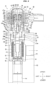
Fig. 3 is a vertical cross sectional view showing the evaporating pressure regulating valve in an initial state in which an adjustment member is moved down until it is stopped by a stopper member according to the first embodiment. -
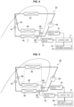
Fig. 4 is a view of an air-conditioning system in a state in which it constructs a building air-conditioning system and performs a cooling operation as an example provided with the evaporating pressure regulating valve according to the first embodiment, which is shown on a Mollier chart. -
Fig. 5 is a view of the air-conditioning system in a state in which it constructs a car air-conditioner and performs a heating and dehumidifying operation as the other example provided with the evaporating pressure regulating valve according to the first embodiment, which is shown on a Mollier chart. -
Fig. 6 is a vertical cross sectional view showing an evaporating pressure regulating valve (in a valve-closed state, a state in which an exciting coil is not energized, and a state in which a plunger displaces to an upper limit position) according to a second embodiment of the present invention. -
Fig. 7 is a vertical cross sectional view showing the evaporating pressure regulating valve (in a valve-closed state, and a state in which the plunger displaces to a lower limit position where the plunger comes into collision with a suction element) according to the second embodiment. -
Fig. 8 is a vertical cross sectional view showing the evaporating pressure regulating valve (in a valve-closed state, and a state in which the plunger is displaced to an intermediate position between the upper limit position and the lower limit position by adjusting a supply current to an exciting coil) according to the second embodiment. -
Fig. 9 is a diagram showing a relationship between a flow rate of a refrigerant and a control pressure in a mechanical pressure regulating valve. -
Fig. 10 is a diagram showing the relationship between the flow rate of the refrigerant and the control pressure in the mechanical pressure regulating valve, and describes an operation for adjusting a biasing force of the pressure sensitive member when shipping the regulating valve. -
Fig. 11 is a diagram showing the relationship between the flow rate of the refrigerant and the control pressure in the mechanical pressure regulating valve, and shows a state in which the biasing force of the pressure sensitive member is changed on the basis of the present invention. -
Fig. 12 is a flowchart showing an example of a process which a control part executes for optimally air conditioning each of living spaces in an air-conditioning system provided with the regulating valve according to the first embodiment. - A description will be given of a pressure regulating valve according to a first embodiment of the present invention with reference to
Figs. 1 to 5 . Apressure regulating valve 11 according to the present embodiment (same applies to a second embodiment mentioned later) is an evaporating pressure regulating valve (hereinafter, refer also to as "pressure regulating valve" or "regulating valve") which is disposed in an outlet side piping of an evaporator of an air-conditioning system and holds the pressure within the evaporator above a certain magnitude. Further, each of the drawings appropriately shows a two-dimensional orthogonal coordinate system indicating each of upper, lower, right and left directions, and the following description will be given on the basis of these directions. - As shown in
Figs. 1 and2 , the evaporating pressure regulating valve 11 according to the first embodiment of the present invention is provided with a valve main body 12 having a valve chamber 13 which is communicated with an inflow passage 14 introducing a refrigerant and an outflow passage 15 discharging the refrigerant, a valve body 17 changing a flow rate of the refrigerant by advancing and retracting (moving upward and downward) with respect to a valve seat 16 formed within the valve chamber 13 between a valve-closed state (refer toFig. 1 ) in which the valve body 17 comes into contact with the valve seat 16, and a valve-opened state (refer toFig. 2 ) in which the valve body 17 is spaced apart from the valve seat 16, a pressure sensitive bellows (a pressure sensitive member, hereinafter simply refer also to as "bellows") 21 which allows the valve body 17 to move up and down by biasing the valve body 17 toward the valve seat 16 and expanding and contracting according to a pressure which the valve body 17 is applied from the refrigerant flowing into from the inflow passage 14, an adjustment member 24 which adjusts a load (a biasing force) applied from the pressure sensitive bellows 21 to the valve body 17, an electric actuator 40 which moves the adjustment member 24 in a vertical direction, an actuator connection member (hereinafter, refer simply to as "connection member") 28 which connects the electric actuator 40 to the valve main body 12 via an upper lid 27 closing an upper portion (an upper surface opening 12a) of the valve chamber 13, and a stopper member 29 which controls (physically or mechanically stops) a downward movement of the adjustment member 24. - Further, the
valve chamber 13 is disposed in an intermediate portion of the valvemain body 12 in a vertical direction, and theinflow passage 14 communicating with thevalve chamber 13 extends vertically upward from a lower surface of the valvemain body 12 and is open to a bottom surface portion of thevalve chamber 13. Further, thevalve seat 16 is formed in an upper edge portion of theinflow passage 14 in which theinflow passage 14 is open to thevalve chamber 13. On the other hand, theoutflow passage 15 extends horizontally (rightward inFigs. 1 to 2 ) from a side surface of thevalve chamber 13, and is open to a peripheral surface of the valvemain body 12. - The pressure sensitive bellows 21 is provided with a bellows
main body 22 which is formed into a cylindrical shape having one end opened and other end bottomed and its peripheral wall is formed into a bellows, and acompression coil spring 23 which is accommodated in an inner portion of the bellowsmain body 22 in a compressed state, and thevalve body 17 is connected to a lower end portion of the pressuresensitive bellows 21 via aconnection plate 18. Further, an upper surface of the bellowsmain body 22 is closed by bonding theadjustment member 24. More specifically, theadjustment member 24 has a disc-like flange portion 25, and aguide shaft portion 26 which rises vertically upward from a center portion of theflange portion 25, and closes an upper surface of the bellowsmain body 22 by welding theflange portion 25 to the upper surface of the bellowsmain body 22. - The
upper lid 27 closing the upper portion of thevalve chamber 13 is provided with an upper lid main body 27a which is fixed by being screwed into the upper surface opening 12a of the valvemain body 12, and aflange portion 27b which expands horizontally outward from an upper surface portion of the upper lid main body 27a and comes into contact with the upper surface of the valvemain body 12, and is a cup-shaped member having one end opened and other end bottomed which has a connectionmember accommodating hole 27c receiving theconnection member 28 in an upper surface side of the upper lid main body 27a. Theupper lid 27 has abottom hole 27e which passes through a bottom plate portion (also called as "upper lid bottom plate portion") of the upper lid main body 27a and allows theguide shaft portion 26 of theadjustment member 28 to slidably insert in a vertical direction, in a center portion of the connectionmember accommodating hole 27c. Further, astopper member 29 is disposed between a bottom surface of the connectionmember accommodating hole 27c (an upper surface of the upper lidbottom plate portion 27d) and a lower surface of theconnection member 28, and a space S allowing thestopper member 29 to be movable up and down is formed (this space is called as "stopper configuration space"). - In the meantime, the
connection member 28 is a tubular member having a large-diameter hole 28a and a small-diameter hole 28b which are mutually communicating through holes. The large-diameter hole 28a passes through an upper portion of theconnection member 28, and has a large diameter in such a manner as to allow a bearingmember 34 mentioned later to be fitted and inserted into from the above. The small-diameter hole 28b passes through a lower portion of theconnection member 28 and has a small diameter. An upper end portion of theguide shaft portion 26 is fitted and inserted into the small-diameter hole 28b from the below so as to be slidable in a vertical direction. In the present embodiment, theupper lid 27, theconnection member 28 and the bearingmember 34 are fitted and inserted in a nested manner. Thus, theelectric actuator 40 is installed in the upper surface portion of the valvemain body 12. - The
guide shaft portion 26 of theadjustment member 24 passes through thebottom plate portion 27d of the upper lid main body 27a from the upper portion of thevalve chamber 13, and an upper end portion thereof is inserted into the small-diameter hole 28b through the stopper configuration space S. Thestopper member 29 is installed in an intermediate portion (a portion extending into the stopper configuration space S) of theguide shaft portion 26. Thestopper member 29 is a ring member which is fixed to theguide shaft portion 26 so as to protrude to a periphery horizontally (like a flange) from an outer peripheral surface of theguide shaft portion 26 and has a flat C shape. As will be mentioned later in detail, thestopper member 29 performs a function for physically (mechanically) stopping theadjustment member 24 by coming into contact with the upper surface of the upper lidbottom plate portion 27d (the bottom surface of the connectionmember accommodating hole 27c) when theelectric actuator 40 moves theadjustment member 24 downward. - A shape and a configuration of the
stopper member 29 are not limited as long as thestopper member 29 has the function for mechanically stopping theadjustment member 24. For example, thestopper member 29 may be constructed by an O-shaped ring member which protrudes outward from an outer peripheral surface of theguide shaft portion 26, a rod-like (pin-like) member or a plate-like member which passes through theguide shaft portion 26 and protrudes out of the outer peripheral surface of theguide shaft portion 26 in one end or both ends. - The
electric actuator 40 is constructed by a steppingmotor 41, a speed reduction mechanism (a paradox planetary gear speed reduction mechanism) 54 which decelerates the rotation achieved by the steppingmotor 41, and a transmission mechanism (a screw feeding mechanism 36) which converts the decelerated rotating motion into a linear motion and transmits to the bellows 21 (theguide shaft portion 26 of the adjustment member 24). The details are as follows. - A
cylindrical can 56 which is covered and not bottomed (is opened in a bottom surface and is closed in a top surface) is bonded to an upper end portion of theconnection member 28 via a ring-like base plate 57, astator 42 is disposed in an outer periphery (outer side) of thecan 56, and arotor 47 is rotatably installed in an inner periphery (inner side) of thecan 56. Therotor 47 and thestator 42 construct the steppingmotor 41. - The
stator 42 disposed in the outer side of thecan 56 includes ayoke 43, abobbin 43, acoil 45, and aresin mold cover 46. Therotor 47 disposed in the inner side of thecan 56 is constructed by integrally connecting acylindrical rotor member 47a which is produced by a magnetic material, and asun gear member 48 which is produced by a resin material. Ashaft 38 is inserted into a center portion of thesun gear member 48, and an upper portion of theshaft 38 is supported by asupport member 39 which is disposed in an inner side of a top portion of thecan 56. - A
sun gear 48a of thesun gear mechanism 48 engages with a plurality ofplanetary gears 49 rotatably supported to ashaft 50 which is disposed in acarrier 51 mounted on a bottom surface of anoutput gear 53. An upper portion of theplanetary gear 49 engages with an annular ring gear (an internal fixed gear) 55 attached to an upper portion of thecylindrical member 37 which is fixed to the upper portion of theconnection member 28, and a lower portion of theplanetary gear 49 engages with aninternal tooth gear 52 of theannular output gear 53. The number of teeth of the ring gear 55 is set to be slightly different from the number of teeth of theinternal tooth gear 52 of theoutput gear 53. Thus, the number of rotation of thesun gear 48a is decelerated with a great deceleration ratio and is transmitted to theoutput gear 53. The gear mechanisms (thesun gear 48a, theplanetary gear 49, the ring gear 55 and the output gear 53) construct the speed reduction mechanism (the paradox planetary gear speed reduction mechanism) 54 which decelerates the rotation of the steppingmotor 41 mentioned above. - A
tubular bearing member 34 is fitted and inserted into the upper portion of theconnection member 28, and is fixed to theconnection member 28 by caulking. Theoutput gear 53 is slidably in contact with an upper surface of the bearingmember 34. Further, an upper portion of a steppedcylindrical output shaft 58 is pressed into the center of a bottom portion of theoutput gear 53, and a lower portion of theoutput shaft 58 is rotatably inserted into aninsertion hole 34a which is formed in an upper surface portion of the center portion of the bearingmember 34. Further, a lower end portion of theshaft 38 is fitted to the upper portion of theoutput shaft 58 so as to be relatively rotatable. - A
female screw portion 34b is formed in a lower portion of the center portion of the bearingmember 34, and amale screw portion 35a formed on an outer peripheral surface of thescrew drive member 35 threadably engages with thefemale screw portion 34b. The bearing member 34 (thefemale screw portion 34b) and the screw drive member 35 (themale screw portion 35a) construct the transmission mechanism which converts the rotating motion supplied from the steppingmotor 41 via thescrew feeding mechanism 36 mentioned above, that is, thespeed reduction mechanism 54 into the linear motion in the vertical direction and transmits to the bellows 21 (theguide shaft portion 26 of the adjustment member 24). - Here, the
output gear 53 performs a rotating motion at a fixed position in the vertical direction without moving up and down, and the rotating motion of theoutput gear 53 is transmitted to thescrew drive member 35 side by inserting a plate-like portion 35b which is disposed in an upper end portion of thescrew drive member 35 and has a flat driver shape into afitting groove 58a which is disposed in a lower end portion of theoutput shaft 58 connected to theoutput gear 53 and has a slit shape. The plate-like portion 35b disposed in thescrew drive member 35 slides in the vertical direction within thefitting groove 58a of theoutput shaft 58, so that the output gear 53 (the rotor 47) rotates. Thus, thescrew drive member 35 linearly moves in the vertical direction by thefeeding mechanism 36 in spite of no linear motion of theoutput gear 53 in the vertical direction. - The linear motion of the
screw drive member 35 is transmitted to theguide shaft portion 26 via a ball-like joint 31 which is constructed by aball 33, and aball receiving seat 32 fitted tofitting hole 26a disposed in a center portion of an upper surface of theguide shaft portion 26. Theguide shaft portion 26 is (accordingly theadjustment member 24 is also) guided by the small-diameter hole 28b of theconnection member 28 and thebottom hole 27e of the upper lidbottom plate portion 27d and moves in the vertical direction. - Here, a description will be briefly given of a motion of the regulating
valve 11 according to the present embodiment. When the refrigerant pressure within the evaporator connected to theinflow passage 14 via the piping becomes smaller than a set load of the pressuresensitive bellows 21 biasing thevalve body 17, thevalve body 17 moves toward thevalve seat 16 by being pushed by the biasing force of the pressuresensitive bellows 21, and the flow rate of the refrigerant is reduced. On the contrary, when the refrigerant pressure within the evaporator becomes greater than the set load of the pressuresensitive bellows 21 biasing thevalve body 17, thevalve body 17 moves in a direction of moving away from thevalve seat 16 by being pushed by the refrigerant pressure within the inflow passage 14 (within the evaporator), and the flow rate of the refrigerant is increased. - In order to allow the set load of the pressure
sensitive bellows 21 to be changeable by embedding the regulatingvalve 11 according to the present embodiment in the air-conditioning system and using thestopper member 29, for example, the following processes should be previously performed. - First of all, an initialization operation is performed. In particular, the electric actuator 40 (the stepping motor 41) is driven and the
adjustment member 24 is moved downward to an initial position, that is, until thestopper member 29 comes into contact with the bottom surface of the connectionmember accommodating hole 27c (the upper surface of the upper lidbottom plate portion 27d) as shown inFig. 3 and theadjustment member 24 is accordingly stopped. - Next, the
electric actuator 40 is driven while supplying the refrigerant (or air) to theinflow passage 14 and theadjustment member 24 is moved upward from the initial position until the pressure within theinflow passage 14 comes to a first pressure value (a first evaporating pressure). During the same period, the number of drive pulse of the stepping motor is counted, and the counted value (the number of pulse) is saved as a first set value. - Further, after performing the initialization operation again (after returning the
adjustment member 24 to the initial position), theelectric actuator 40 is driven while supplying the refrigerant (or air) to theinflow passage 14 in the same manner, and theadjustment member 24 is moved upward until the pressure within theinflow passage 14 comes to a second pressure value (a second evaporating pressure) which is different from the first pressure value (the first evaporating pressure). During the same period, the number of drive pulse of the steppingmotor 41 is counted, and the counted value (the number of pulse) is saved as a second set value. - Then, the first set value and the second set value which are obtained by the operation mentioned above are stored in a storage device disposed in a control part which controls a system (for example, an air-conditioning system such as a car air-conditioner and a room air-conditioner, or a freezing ad refrigerating system such as a freezer refrigerator) using the regulating
valve 11 according to the present embodiment, and theelectric actuator 40 can be drive by the control part. Thus, the refrigerant pressure within the evaporator can be set to the first evaporating pressure and the second evaporating pressure according to an operation condition of the system. - Further, by measuring the number of pulse coming to three or more pressure values (evaporating pressures), that is, a third pressure value (a third evaporating pressure), a fourth pressure value (a fourth evaporating pressure), a fifth pressure value (a fifth evaporating pressure), ..., and respectively saving them as a third set value, a fourth set value, a fifth set value, ..., similarly, it is possible to switch the setting of the evaporator to three of more evaporating pressures on the basis of three or more set values of the regulating
valve 11. - Each of the set values mentioned above (each of the evaporating pressures) may be an optional value corresponding to a configuration and an operation condition of the system. A description will be given later of an example in which the regulating
valve 11 according to the present embodiment is embedded in the air-conditioning system. In this description, the first set value may be set, for example, to a standard set value mentioned layer, the second set value may be set, for example, to a high temperature side set value mentioned later, and the third set value may be set, for example, to a low temperature set value mentioned later. - Further, in a case where the regulating
valve 11 according to the present embodiment is used in the car air-conditioner, each of the set values can be stored in a storage device (ROM (Read Only Memory) or RAM (Random Access Memory) or flash memory) which is mounted to a LIN (Local Interconnect Network) board or separately disposed. Further, in a case where it is used in the room air-conditioner, they can be stored in a similar storage device which is mounted to a control board of the room air-conditioner or separately disposed. -
Fig. 4 shows a building air-conditioning system 61 which is provided with the evaporatingpressure regulating valve 11 according to the present embodiment. As shown in this drawing, the air-conditioning system 61 is provided with each of elements constructing the refrigeration cycle, that is, acompressor 62 which compresses the refrigerant, anoutdoor heat exchanger 63 which is installed outdoor, a firstindoor heat exchanger 64 which is installed within a first living space, a secondindoor heat exchanger 65 which is installed within a second living space, afirst expansion valve 66 which is connected to an inlet side piping of the first indoor heat exchanger 64 (between theoutdoor heat exchanger 63 and the first indoor heat exchanger 64), asecond expansion valve 67 which is connected to an inlet side piping of the second indoor heat exchanger 65 (between theoutdoor heat exchanger 63 and the second indoor heat exchanger 65), a firstpressure regulating valve 68 which is connected to an outlet side piping of the first indoor heat exchanger 64 (between the firstindoor heat exchanger 64 and the compressor 62), and a secondpressure regulating valve 69 which is connected to an outlet side piping of the second indoor heat exchanger 65 (between the secondindoor heat exchanger 65 and the compressor 62). Both the firstpressure regulating valve 68 and the secondpressure regulating valve 69 are constructed by thepressure regulating valve 11 according to the present embodiment. - Further, the
system 61 is further provided with acontrol part 71 which controls the setting of each of thepressure regulating valves 68 and 69 (the biasing force of the pressure sensitive bellows 21), a set value storage portion (a storage device) 72 which stores the set values, andmotor drive circuits control part 71 and the setvalue storage portion 72 are mounted on the control board 70 of the air-conditioning system 61. - Further, in the set
value storage portion 72, there are stored three (three kinds of) set values, that is, a standard set value (this is called as "standard value", and the setting by the standard value is called as "standard setting"), a high temperature side set value for shifting to a higher temperature side than the standard setting (increasing the biasing force of the pressuresensitive bellows 21 for enhancing the refrigerant pressure within the evaporator, that is, positioning theadjustment member 24 below the standard setting) (the setting by the set value is called as "high temperature side setting"), and a low temperature side set value for shifting to a lower temperature side than the standard setting (decreasing the biasing force of the pressure sensitive bellows for lowering the refrigerant pressure within the evaporator, that is, positioning the adjustment member above the standard setting) (the setting by the set value is called as "low temperature side setting"). -
Fig. 4 shows a state in which the cooling operation is performed. The refrigerant discharged from thecompressor 62 flows through a route passing via theoutdoor heat exchanger 63, thefirst expansion valve 66, the firstindoor heat exchanger 64 and the firstpressure regulating valve 68 in this order and returning to thecompressor 62, and a route passing via theoutdoor heat exchanger 63, thesecond expansion valve 67, the secondindoor heat exchanger 65 and the secondpressure regulating valve 69 in this order and returning to thecompressor 62. Theoutdoor heat exchanger 63 functions as a condenser, and the firstindoor heat exchanger 64 and the secondindoor heat exchanger 65 both function as an evaporator. Further, the firstpressure regulating valve 68 connected to the outlet side piping of the firstindoor heat exchanger 64 and the secondpressure regulating valve 69 connected to the outlet side piping of the secondindoor heat exchanger 65 are assumed to be both set standard. - In a case where the cooling load changes in such a manner that the living spaces (the
indoor heat exchangers 64 and 65) are greatly different during the cooling operation in the system mentioned above, for example, on the assumption that the number of person staying in the first living space is widely increased and the cooling load of the firstindoor heat exchanger 64 becomes large, and the number of person staying in the second living space is widely reduced and the cooling load of the secondindoor heat exchanger 65 becomes small, the following situation occurs. More specifically, in thesystem 61 inFig. 4 , by changing the setting of the secondpressure regulating valve 69 to the high temperature side setting and the setting of the firstpressure regulating valve 68 to the low temperature side setting, it is possible to more securely prevent the frost formation in the secondindoor heat exchanger 65, and it is possible to avoid or suppress occurrent of the situation that the cooling capacity in the first living space having the great cooling load becomes insufficient. - In particular, the
control part 71 reads the high temperature side set value from the setvalue storage portion 72, sends a drive pulse corresponding to the high temperature side set value to the secondpressure regulating valve 69 via themotor drive circuit 74 and drives the steppingmotor 41, after initializing the second pressure regulating valve 69 (moving theadjustment member 24 to the initial position) by driving the steppingmotor 41 via themotor drive circuit 74. Thus, theadjustment member 24 moves to the high temperature side setting position from the initial position, and the secondpressure regulating valve 69 comes to the high temperature side setting. Further, in the same manner, thecontrol part 71 reads the low temperature side set value from the setvalue storage portion 72, sends a drive pulse corresponding to the low temperature side set value to the firstpressure regulating valve 68 via themotor drive circuit 73 and drives the steppingmotor 41, after initializing the firstpressure regulating valve 68 by driving the steppingmotor 41 via themotor drive circuit 73. Thus, theadjustment member 24 moves to the low temperature side setting position from the initial position and the firstpressure regulating valve 68 comes to the low temperature side setting. - The setting change by the
control part 71 may be automatically, that is, thecontrol part 71 may automatically execute the setting change on the basis of a detected signal from a sensor (for example, a temperature sensor detecting an air temperature within the living space or a human detecting sensor detecting the number of person staying in the room, not illustrated), or the setting change may be executed by a manual operation, that is, an input operation from an input device (for example, a remote control device (so-called remote controller, not illustrated). - Further, only two indoor heat exchangers are illustrated in
Fig. 4 . However, a greater number of (three or more) indoor heat exchangers (expansion valves and pressure regulating valves) may be provided, and these indoor heat exchangers can be controlled (changed setting) by thecontrol part 71 in the same manner as the first indoor heat exchanger (the first pressure regulating valve) and the second indoor heat exchanger (the second pressure regulating valve). - Further,
Fig. 12 shows an example of a processing flow for optimally air-conditioning controlling each of the living spaces in the air-conditioning system as shown inFig. 4 . In this example, in order to suppress a difference (a temperature difference) between an actually measured temperature (an actual temperature) within the living space and a set temperature to a fixed temperature range, the control part is adapted to acquire the set temperature and the actual temperature of each of the living spaces (for example, via an indoor communication line) as well as previously storing an upper limit threshold value (an upper limit value of the temperature difference) and a lower limit threshold value (a lower limit value of the temperature difference) in the set value storage portion, in addition to the standard value (the standard set value), the high temperature side set value and the low temperature side set value. - In the processing achieved by the control part, the control part reads the standard set value from the set value storage portion and sets the regulating value of each of the living spaces to a standard one first of all (for example, when the power supply of the air-conditioning system is turned on) (step S101). Next, the control part acquires the set temperature of each of the living spaces rooms (step S102), and acquires the actual temperature of each of the living spaces rooms (step S103).
- Then, the control part compares the difference (the temperature difference) between the actual temperature and the set temperature with the upper limit threshold value for each of the living spaces (step S104), and changes the regulating value of the living space (the living space in which the temperature difference becomes greater than the upper limit threshold value) to the low temperature side setting in a case where the temperature difference is greater than the upper limit threshold value (step S106). For example, if the set temperature is "22 °C" and the actual temperature is "26 °C" in a case where the upper limit threshold value is set to "3 °C", and the lower limit threshold value is set to "-3 °C", the temperature difference (+ 4 °C) is greater than the upper limit threshold value (3 °C). Therefore, the change to the low temperature side setting is performed by the control part.
- On the contrary, in a case where the temperature difference does not go beyond the upper limit threshold value (there is no living space in which the temperature difference goes beyond the upper limit threshold value), and after the setting change to the low temperature side (step S106) is finished, the temperature difference and the lower limit threshold value are compared for each of the living spaces (step S105). Then, in a case where the temperature difference is smaller than the lower limit threshold value, the regulating valve of the living space (the living space in which the temperature difference becomes smaller than the lower threshold value) is changed to the high temperature side setting (step S107). For example, if the set temperature is "25 °C" and the actual temperature is "20 °C" in a case where the upper limit threshold value is set to "3 °C", and the lower limit threshold value is set to "-3 °C", the temperature difference (- 5 °C) is smaller than the lower limit threshold value (-3 °C). Therefore, the change to the high temperature side setting is performed by the control part.
- On the other hand, in a case where the temperature difference does not become smaller than the lower limit threshold value (there is no living space in which the temperature difference becomes smaller than the lower limit threshold value), and after the setting change to the high temperature side (step S107) is finished, the step goes back to the step S102 of acquiring the set temperature of each of the living spaces.
- The control part repeats the processes (steps S102 to S107) as mentioned above for a fixed time interval (for example, every five minutes or every ten minutes). Thus, it is possible to achieve a good air-conditioning control in which the actual room temperature of each of the living spaces is within a fixed error range (between the upper limit threshold value and the lower limit threshold value) from the set temperature.
- The example mentioned above is adapted to regulate the biasing force for every one stage to the high temperature side and the lower temperature side by the provision of one threshold value and one set value in each of the high temperature side and the low temperature side. However, the biasing force of the pressure sensitive bellows can be changed in multiple stages by setting a plurality of threshold values and set values in each of the high temperature side and the low temperature side, thereby performing a finer control.
- Further, it is possible to change the setting of the biasing force of the pressure sensitive bellows according to the number of person staying in the living space with the use of the human detecting sensor, in place of the temperature, for example, according to the difference in the number of person (the difference between the number of person actually staying in the space and the previously determined number of capacity in the living space) in place of the temperature difference.
-
Fig. 5 shows a car air-conditioner system 81 which is provided with the evaporating pressure regulating valve according to the present embodiment. The air-conditioning system 81 is provided with each of elements constructing a heat pump cycle, that is, acompressor 62, a first cabinindoor heat exchanger 82 which is installed within a vehicle interior, a second cabinindoor heat exchanger 83 which is installed within the vehicle interior, a cabinoutdoor heat exchanger 84 which is installed out of the vehicle interior, afirst expansion valve 66 which is connected to an inlet side piping of the second cabin indoor heat exchanger 83 (between the first cabinindoor heat exchanger 82 and the second cabin indoor heat exchanger 83), asecond expansion valve 67 which is connected to an inlet side piping of the cabin outdoor heat exchanger 84 (between the first cabinindoor heat exchanger 82 and the cabin outdoor heat exchanger 84), a firstpressure regulating valve 68 which is connected to an outlet side piping of the second cabin indoor heat exchanger 83 (between the second cabinindoor heat exchanger 83 and the compressor 62), and a secondpressure regulating valve 69 which is connected to an outlet side piping of the cabin outdoor heat exchanger 84 (between the cabinoutdoor heat exchanger 84 and the compressor 62). - Further, this is the same as the building air-
conditioning system 61 shown inFig. 4 , in a point that the firstpressure regulating valve 68 and the secondpressure regulating valve 69 are both constructed by thepressure regulating valve 11 according to the present embodiment, and thesystem 81 is provided with thecontrol part 71 which controls the setting of each of thepressure regulating valves value storage portion 72 which stores the set values, and themotor drive circuits control part 71 and the setvalue storage portion 72 are mounted on a LIN (Local Interconnect Network)board 85 in the present embodiment. Further, in thepresent system 81, the standard value, the high temperature side set value and the low temperature side set value are previously stored in the setting storage portion, and the firstpressure regulating valve 68 and the secondpressure regulating valve 69 are both set to the standard setting initially. - Further, the refrigerant discharged from the
compressor 62 flows through a route passing via the first cabinindoor heat exchanger 82, thefirst expansion valve 66, the second cabinindoor heat exchanger 83 and the firstpressure regulating valve 68 in this order and returning to thecompressor 62, and a route passing via the first cabinindoor heat exchanger 82, thesecond expansion valve 67, the cabinoutdoor heat exchanger 84 and the secondpressure regulating valve 69 in this order and returning to thecompressor 62. The firstindoor heat exchanger 82 functions as a condenser, and the second cabinindoor heat exchanger 83 and the cabinoutdoor heat exchanger 84 both function as an evaporator. Further, the second cabinindoor heat exchanger 83 functioning as the evaporator is adapted to achieve a dehumidification function by being arranged in an air blowing route for hot air which is heat exchanged by the first cabinindoor heat exchanger 82 and heated. - In the
system 81 mentioned above, for example, assuming that a warming and dehumidification operation is performed for heating and simultaneously defogging a vehicle window at rainfall time and snowfall time during the winter season, the second cabinindoor heat exchanger 83 becomes lower temperature and can enhance the dehumidification function by changing the setting of the firstpressure regulating valve 68 to the low temperature side setting in thesystem 81 ofFig. 5 . Further, by changing the setting of the second pressure regulating valve to the high temperature side setting, it is possible to more securely prevent the frost formation of the cabinoutdoor heat exchanger 84 which is installed in an outer side of the vehicle interior, is exposed to the ambient air and tends to form frost. - In particular, the
control part 71 initializes the first pressure regulating valve by driving the steppingmotor 41 via the motor drive circuit 73 (moves theadjustment member 24 to the initial position), thereafter reads the low temperature side set value from the setvalue storage portion 72, sends the drive pulse corresponding to the low temperature side set value to the firstpressure regulating valve 68 via themotor drive circuit 73, and drives the steppingmotor 41. Thus, theadjustment member 24 moves to the low temperature side setting position from the initial position, and the firstpressure regulating valve 68 comes to the low temperature side setting. Further, thecontrol part 71 initializes the second pressure regulating valve by driving the steppingmotor 41 via themotor drive circuit 74, thereafter reads the high temperature side set value from the setvalue storage portion 72, sends the drive pulse corresponding to the high temperature set value to the secondpressure regulating valve 69 via themotor drive circuit 74, and drives the steppingmotor 41. Thus, theadjustment member 24 moves to the high temperature side setting position from the initial position, and the secondpressure regulating valve 69 comes to the high temperature side setting. - A description will be given of a pressure regulating valve according to a second embodiment of the present invention with reference to
Figs. 6 to 8 . As shown inFigs. 6 to 8 , a regulatingvalve 91 according to the present embodiment is provided with the valvemain body 12, thevalve body 17 and the pressuresensitive bellows 21 in the same manner as the regulatingvalve 11 according to the first embodiment, and has thevalve chamber 13, thevalve seat 16, theinflow passage 14 and theoutflow passage 15. However, this regulatingvalve 91 uses anelectromagnetic actuator 92 as an actuator for displacing theadjustment member 24, in place of the electric actuator. Hereinafter, an overlapping description will be omitted by attaching the same reference numerals to the same configurations as those of the regulatingvalve 11 according to the first embodiment, and a description will be given mainly of different points. - The
electromagnetic actuator 92 has asolenoid 93, a plunger (a moving core) 97, and athrust transmission member 98 which connects theplunger 97 andadjustment member 24 and transmits an up-and-down motion of theplunger 97 to theadjustment member 24 via the ball-like joint 31 (theball 33 and the ball receiving seat 32). Thesolenoid 93 has anexciting coil 96, and a suction element (a fixed core) 95 which attracts theplunger 97. Theexciting coil 96 has abobbin 94 which has a tubular portion in its center, and is arranged within the tubular portion of thebobbin 94 in a state in which an upper portion (a suction elementmain body portion 95a) of thesuction element 95 and theplunger 97 are accommodated in asleeve 99. - The
suction element 95 is constructed by the suction elementmain body portion 95a which attracts theplunger 97 and has a columnar shape, and a disc-likeupper lid portion 95b which closes the upper portion of thevalve chamber 13, and the suction elementmain body portion 95a and theupper lid portion 95b are integrally formed. Theupper lid portion 95b is fixed to the valvemain body 12 by being screwed into the upper surface opening 12a of the valvemain body 12 in the same manner as theupper lid 27 according to the first embodiment, so that the upper portion of thevalve chamber 13 is closed. - Further, a through
hole 95c extending in a vertical direction is formed in a center portion of thesuction element 95, thethrust transmission member 98 is fitted and inserted into an upper portion of the throughhole 95c so as to be slidable in the vertical direction, and theguide shaft portion 26 of theadjustment member 24 is fitted and inserted into a lower portion of the throughhole 95c so as to be slidable in the vertical direction. Further, the ball-like joint 31 constructed by theball 33 and theball receiving seat 32 is interposed between thethrust transmission member 98 and theguide shaft portion 26. Thus, a thrust toward a lower side of thethrust transmission member 98 generated by a downward movement of theplunger 97 is transmitted to theguide shaft portion 26, and a resilient force toward an upper side of the pressure sensitive bellows 21 (a reaction force to the biasing force toward the valve body 17) and a force toward an upper side of theguide shaft portion 26 in association with an upward movement of thevalve body 17 are transmitted to thethrust transmission member 98. - The regulating
valve 91 according to the present embodiment is provided in an upper surface portion of thebellows 21 with thesame adjustment member 24 as the first embodiment but is not provided in theguide shaft portion 26 with a stopper member. - In a state in which the
exciting coil 96 is not energized, there is formed a state in which thevalve body 17 is pressed to thevalve seat 16, the adjustment member 24 (the flange portion 25) is pressed to the lower surface of theupper lid portion 95b and theplunger 97 is pressed to a lower surface of a top plate portion of the sleeve 99 (the position of theplunger 97 is called as "upper limit position") by the resilient force of the pressuresensitive bellows 21 as shown inFig. 6 . - On the contrary, when the
exciting coil 96 is energized, thesuction element 95 sucks theplunger 97 against the resilient force of the pressuresensitive bellows 21 as shown inFig. 7 , and theadjustment member 24 is pressed downward via thethrust transmission member 98 and the ball-like joint 31. The position of the plunger shown inFig. 7 is called as "lower limit position". - Here, a stop position of the
plunger 97, that is, a position of theadjustment member 24 in the vertical direction is determined by a balance of the upward resilient force of the pressure sensitive bellows 21 (the reaction force of the biasing force toward the valve body 17), and a suction force (a magnitude of a drive current supplied to the solenoid 93) of the solenoid 93 (the suction element 95). More specifically, when the suction force (the strength of the magnetic force) of thesuction element 95 is sufficiently large, theplunger 97 moves down to a lower limit position where theplunger 97 comes into collision with the suction element as shown inFig. 7 . However, the plunger 97 (the adjustment member 24) can be stopped at an optional intermediate position between the upper limit position shown inFig. 6 and the lower limit position shown inFig. 7 by adjusting the drive current supplied to theexciting coil 96 and weakening the suction force of the suction element 95 (refer toFig. 8 ). - Therefore, the control part can be used by measuring the magnitude of the drive current by which the pressure within the
inflow passage 14 comes to the first pressure value (the first evaporating pressure) and setting it to the first set value, measuring the magnitude of the drive current by which the pressure within theinflow passage 14 comes to the second pressure value (the second evaporating pressure) and setting it to the second set value, and storing the first set value and the second set value in the set value storage portion of the system (the air-conditioning system), in the same manner as the first embodiment. In this case, the control part can change the magnitude of the electric current supplied to theexciting coil 96 on the basis of each of the set values and can perform the setting change of thepressure regulating valve 91. - The number of the set value is not limited to two, but the setting change can be performed on the basis of three or more set values (the third set value, the fourth set value, ...) in the same manner as the first embodiment.
- The description is given above of the embodiments according to the present invention. However, it is apparent for a person skilled in the art that the present invention is not limited to them and can be variously changed within the scope of claims.
- For example, the initialization is performed by bringing the
stopper member 29 into contact with the bottom surface of the connectionmember accommodating hole 27c (the upper surface of the upper lidbottom plate portion 27d) in the first embodiment. However, the operation can achieve the purpose thereof as long as the operation can mechanically stop theadjustment member 24. Therefore, a place where thestopper member 29 is brought into contact may be the other places (the other members or portion) within the regulating valve. -
- 11, 91 evaporating pressure regulating valve
- 12 valve main body
- 12a upper surface opening
- 13 valve chamber
- 14 inflow passage
- 15 outflow passage
- 16 valve seat
- 17 valve body
- 18 connection plate
- 21 pressure sensitive bellows
- 22 bellows main body
- 23 compression coil spring
- 24 adjustment member
- 25 flange portion
- 26 guide shaft portion
- 26a fitting hole
- 27 upper lid
- 27a upper lid main body
- 27b flange portion
- 27c connection member accommodating hole
- 27d upper lid bottom plate portion
- 27e bottom hole
- 28 actuator connection member
- 28a large-diameter hole
- 28b small-diameter hole
- 29 stopper member
- 31 ball-like joint
- 32 ball receiving seat
- 33 ball
- 34 bearing member
- 34a insertion hole
- 34b female screw portion
- 35 screw drive member
- 35a male screw portion
- 35b plate-like portion
- 36 screw feeding mechanism
- 37 cylindrical member
- 38 shaft
- 39 support member
- 40 electric actuator
- 41 stepping motor
- 42 stator
- 43 yoke
- 44 bobbin
- 45 coil
- 46 resin mold cover
- 47 rotor
- 47a rotor member
- 48 sun gear member
- 48a sun gear
- 49 planetary gear
- 50 shaft
- 51 carrier
- 52 internal tooth gear
- 53 output gear
- 54 speed reduction mechanism (paradox planetary gear speed reduction mechanism)
- 55 ring gear (internal fixed gear)
- 56 can
- 57 base plate
- 58 output shaft
- 58a fitting groove
- 61 building air-conditioning system
- 62 compressor
- 63 outdoor heat exchanger
- 64 first indoor heat exchanger
- 65 second indoor heat exchanger
- 66 first expansion valve
- 67 second expansion valve
- 68 first pressure regulating valve
- 69 second pressure regulating valve
- 70 control board
- 71 control part
- 72 set value storage portion (storage device)
- 73, 74 motor drive circuit
- 81 car air-conditioner system
- 82 first cabin indoor heat exchanger
- 83 second cabin indoor heat exchanger
- 84 cabin outdoor heat exchanger
- 85 LIN board
- 92 electromagnetic actuator
- 93 solenoid
- 94 bobbin
- 95 suction element
- 95a suction element main body portion
- 95b upper lid portion
- 95c through hole
- 96 exciting coil
- 97 plunger (moving core)
- 98 thrust transmission member
- 99 sleeve
- S stopper configuration space
Claims (8)
- A pressure regulating valve comprising:a vale main body having a valve chamber which is communicated with an inflow passage introducing a refrigerant and an outflow passage discharging the refrigerant;a valve body changing a flow rate of the refrigerant by advancing and retreating with respect to a valve seat between a valve-closed state in which the valve body is seated on the valve seat formed within the valve chamber and a valve-opened state in which the valve body is spaced apart from the valve seat;a pressure sensitive member allowing an advancing and retracting movement of the valve body by biasing the valve body toward the valve seat and expanding and contracting according to a pressure which the valve body is applied from the refrigerant flowing into from the inflow passage; andan adjustment means which adjusts a biasing force applied to the valve body of the pressure sensitive member,wherein the pressure regulating valve is provided with an actuator driving the adjustment means.
- The pressure regulating valve according to claim 1, wherein when an end portion in a far side from the valve body among both end portions of the pressure sensitive member is called as a base end portion,the adjustment means includes an adjustment member which is disposed in a base end portion of the pressure sensitive member, andwherein the actuator changes the biasing force by moving the adjustment member in an expanding and contracting direction of the pressure sensitive member.
- The pressure regulating valve according to claim 1 or 2, wherein the actuator is an electric motor.
- The pressure regulating valve according to claim 3, wherein the electric motor is a stepping motor.
- The pressure regulating valve according to any one of claims 1 to 4, wherein the adjustment means is provided with a stopper member which stops the movement of the adjustment member by the actuator and can be set as a starting point when setting the biasing force.
- The pressure regulating valve according to claim 1, wherein when an end portion in a far side from the valve body among both end portions of the pressure sensitive member is called as a base end portion,the adjustment means includes an adjustment member which is disposed in a base end portion of the pressure sensitive member, andwherein the actuator is an electromagnetic actuator which can generate a suction force attracting the adjustment member in a direction of moving close to the valve body, andwherein the biasing force is changeable by changing the suction force.
- The pressure regulating valve according to any one of claims 1 to 6, further comprising a control device which controls the actuator,
wherein the control device comprises:a storage portion which stores two or more set values relating to the biasing force; anda control part which drives the adjustment means via the actuator,wherein the control part drives the adjustment means via the actuator on the basis of the set values which are previously stored in the storage portion, and changes the biasing force of the pressure sensitive member. - The pressure regulating valve according to claim 7, wherein when an end portion in a far side from the valve body among both end portions of the pressure sensitive member is called as a base end portion,the adjustment means includes an adjustment member which is disposed in the base end portion of the pressure sensitive member,wherein the two or more set values are mutually different information relating to the position of the adjustment member about the expanding and contracting direction of the pressure sensitive member, andwherein the control part changes the biasing force by moving the adjustment member via the actuator in the expanding and contracting direction of the pressure sensitive member.
Applications Claiming Priority (2)
| Application Number | Priority Date | Filing Date | Title |
|---|---|---|---|
| JP2021143818 | 2021-09-03 | ||
| PCT/JP2022/027658 WO2023032481A1 (en) | 2021-09-03 | 2022-07-14 | Pressure regulating valve |
Publications (3)
| Publication Number | Publication Date |
|---|---|
| EP4397895A1 true EP4397895A1 (en) | 2024-07-10 |
| EP4397895A4 EP4397895A4 (en) | 2025-07-02 |
| EP4397895B1 EP4397895B1 (en) | 2026-04-29 |
Family
ID=85412104
Family Applications (1)
| Application Number | Title | Priority Date | Filing Date |
|---|---|---|---|
| EP22864069.4A Active EP4397895B1 (en) | 2021-09-03 | 2022-07-14 | Pressure regulating valve |
Country Status (4)
| Country | Link |
|---|---|
| EP (1) | EP4397895B1 (en) |
| JP (1) | JP7629658B2 (en) |
| CN (1) | CN117836549A (en) |
| WO (1) | WO2023032481A1 (en) |
Families Citing this family (1)
| Publication number | Priority date | Publication date | Assignee | Title |
|---|---|---|---|---|
| DE102023202233A1 (en) * | 2023-03-13 | 2024-09-19 | Volkswagen Aktiengesellschaft | Valve control for a refrigerant circuit |
Family Cites Families (9)
| Publication number | Priority date | Publication date | Assignee | Title |
|---|---|---|---|---|
| JPS5416760A (en) * | 1977-07-06 | 1979-02-07 | Okawa Yoshikatsu | Electric vapor pressure regulating valve |
| DE3015980A1 (en) * | 1980-04-25 | 1981-11-05 | Honeywell B.V., Amsterdam | GAS PRESSURE REGULATOR |
| US4637429A (en) * | 1985-10-11 | 1987-01-20 | Honeywell Inc. | Fluid pressure regulating valve having adjustable two-stage and natural-LP gas changeover capabilities |
| JPH0325264A (en) * | 1989-06-23 | 1991-02-04 | Hitachi Ltd | Pressure sensitive type valve drive mechanism and pressure control valve of refrigeration cycle using the same mechanism |
| JPH06300391A (en) * | 1993-04-09 | 1994-10-28 | Nippondenso Co Ltd | Evaporation pressure control valve |
| JP4064582B2 (en) | 1999-10-05 | 2008-03-19 | 株式会社鷺宮製作所 | Evaporation pressure control valve |
| JP4786834B2 (en) * | 2001-09-03 | 2011-10-05 | 株式会社鷺宮製作所 | Motorized valve |
| JP2013221640A (en) | 2012-04-13 | 2013-10-28 | Daikin Industries Ltd | Air conditioner |
| JP6093252B2 (en) | 2013-06-20 | 2017-03-08 | 株式会社不二工機 | Valve device |
-
2022
- 2022-07-14 EP EP22864069.4A patent/EP4397895B1/en active Active
- 2022-07-14 JP JP2023545139A patent/JP7629658B2/en active Active
- 2022-07-14 WO PCT/JP2022/027658 patent/WO2023032481A1/en not_active Ceased
- 2022-07-14 CN CN202280053853.4A patent/CN117836549A/en active Pending
Also Published As
| Publication number | Publication date |
|---|---|
| JP7629658B2 (en) | 2025-02-14 |
| EP4397895A4 (en) | 2025-07-02 |
| JPWO2023032481A1 (en) | 2023-03-09 |
| EP4397895B1 (en) | 2026-04-29 |
| CN117836549A (en) | 2024-04-05 |
| WO2023032481A1 (en) | 2023-03-09 |
Similar Documents
| Publication | Publication Date | Title |
|---|---|---|
| JP5022120B2 (en) | Motorized valves for air conditioning systems | |
| JP5740586B2 (en) | Stepping motor driven control valve | |
| US10240835B2 (en) | Refrigeration cycle device and pilot on-off valve | |
| EP2700853B1 (en) | Control valve | |
| EP2615341B1 (en) | Stepping motor-driven control valve | |
| WO2013172201A1 (en) | Flow rate adjustment valve for refrigeration cycle | |
| KR20080111517A (en) | Solenoid valve and expansion valve device having the same | |
| EP4397895B1 (en) | Pressure regulating valve | |
| JP2008064301A (en) | Pilot type control valve | |
| JP2012220088A (en) | Vehicle heating and cooling apparatus | |
| CN111959223B (en) | Electronic control valve of HVAC system of vehicle and control method of HVAC system | |
| EP1938028B1 (en) | Automated drive for fan and refrigerant system | |
| JP5866600B2 (en) | Vehicle air conditioner, composite valve and control valve | |
| JP5613879B2 (en) | Control valve and vehicle air conditioner | |
| JP4570484B2 (en) | Composite valve, heat pump type air conditioner and control method thereof | |
| JP2013221640A (en) | Air conditioner | |
| JP2011255689A (en) | Air conditioner for vehicle and control valve | |
| WO2012090362A1 (en) | Vehicle heating, ventilation and air conditioning system | |
| EP2015007A1 (en) | Freezer heat exchanger coolant flow divider control device | |
| JP5499299B2 (en) | Control valve and vehicle air conditioner | |
| JP5560439B2 (en) | Control valve and vehicle air conditioner | |
| JP5699267B2 (en) | Control valve | |
| JP2012082908A (en) | Stacked valve | |
| JPH0217278A (en) | Device for controlling opening/closing of motor-driven valve | |
| JP5613956B2 (en) | Differential pressure valve, control valve and vehicle air conditioner |
Legal Events
| Date | Code | Title | Description |
|---|---|---|---|
| STAA | Information on the status of an ep patent application or granted ep patent |
Free format text: STATUS: THE INTERNATIONAL PUBLICATION HAS BEEN MADE |
|
| PUAI | Public reference made under article 153(3) epc to a published international application that has entered the european phase |
Free format text: ORIGINAL CODE: 0009012 |
|
| STAA | Information on the status of an ep patent application or granted ep patent |
Free format text: STATUS: REQUEST FOR EXAMINATION WAS MADE |
|
| 17P | Request for examination filed |
Effective date: 20240304 |
|
| AK | Designated contracting states |
Kind code of ref document: A1 Designated state(s): AL AT BE BG CH CY CZ DE DK EE ES FI FR GB GR HR HU IE IS IT LI LT LU LV MC MK MT NL NO PL PT RO RS SE SI SK SM TR |
|
| TPAC | Observations filed by third parties |
Free format text: ORIGINAL CODE: EPIDOSNTIPA |
|
| DAV | Request for validation of the european patent (deleted) | ||
| DAX | Request for extension of the european patent (deleted) | ||
| REG | Reference to a national code |
Ref country code: DE Ref legal event code: R079 Free format text: PREVIOUS MAIN CLASS: F16K0031040000 Ipc: G05D0016200000 Ref document number: 602022035843 Country of ref document: DE |
|
| A4 | Supplementary search report drawn up and despatched |
Effective date: 20250602 |
|
| RIC1 | Information provided on ipc code assigned before grant |
Ipc: F25B 41/22 20210101ALI20250526BHEP Ipc: F16K 31/06 20060101ALI20250526BHEP Ipc: F16K 31/04 20060101ALI20250526BHEP Ipc: G05D 16/20 20060101AFI20250526BHEP |
|
| GRAP | Despatch of communication of intention to grant a patent |
Free format text: ORIGINAL CODE: EPIDOSNIGR1 |
|
| STAA | Information on the status of an ep patent application or granted ep patent |
Free format text: STATUS: GRANT OF PATENT IS INTENDED |
|
| RIC1 | Information provided on ipc code assigned before grant |
Ipc: G05D 16/20 20060101AFI20251120BHEP Ipc: F16K 31/04 20060101ALI20251120BHEP Ipc: F16K 31/06 20060101ALI20251120BHEP Ipc: F25B 41/22 20210101ALI20251120BHEP Ipc: F16K 31/50 20060101ALI20251120BHEP Ipc: F16K 41/10 20060101ALI20251120BHEP Ipc: F16K 31/53 20060101ALI20251120BHEP |
|
| INTG | Intention to grant announced |
Effective date: 20251219 |
|
| GRAS | Grant fee paid |
Free format text: ORIGINAL CODE: EPIDOSNIGR3 |
|
| GRAA | (expected) grant |
Free format text: ORIGINAL CODE: 0009210 |
|
| STAA | Information on the status of an ep patent application or granted ep patent |
Free format text: STATUS: THE PATENT HAS BEEN GRANTED |
|
| AK | Designated contracting states |
Kind code of ref document: B1 Designated state(s): AL AT BE BG CH CY CZ DE DK EE ES FI FR GB GR HR HU IE IS IT LI LT LU LV MC MK MT NL NO PL PT RO RS SE SI SK SM TR |
|
| REG | Reference to a national code |
Ref country code: CH Ref legal event code: F10 Free format text: ST27 STATUS EVENT CODE: U-0-0-F10-F00 (AS PROVIDED BY THE NATIONAL OFFICE) Effective date: 20260429 Ref country code: GB Ref legal event code: FG4D |