EP4397611A1 - Cable bundle, cable bundle manufacturing method, and cable bundle manufacturing device - Google Patents
Cable bundle, cable bundle manufacturing method, and cable bundle manufacturing device Download PDFInfo
- Publication number
- EP4397611A1 EP4397611A1 EP23869322.0A EP23869322A EP4397611A1 EP 4397611 A1 EP4397611 A1 EP 4397611A1 EP 23869322 A EP23869322 A EP 23869322A EP 4397611 A1 EP4397611 A1 EP 4397611A1
- Authority
- EP
- European Patent Office
- Prior art keywords
- cable
- loop
- bundle
- unit
- bundles
- Prior art date
- Legal status (The legal status is an assumption and is not a legal conclusion. Google has not performed a legal analysis and makes no representation as to the accuracy of the status listed.)
- Pending
Links
Images




Classifications
-
- B—PERFORMING OPERATIONS; TRANSPORTING
- B65—CONVEYING; PACKING; STORING; HANDLING THIN OR FILAMENTARY MATERIAL
- B65H—HANDLING THIN OR FILAMENTARY MATERIAL, e.g. SHEETS, WEBS, CABLES
- B65H55/00—Wound packages of filamentary material
- B65H55/04—Wound packages of filamentary material characterised by method of winding
-
- B—PERFORMING OPERATIONS; TRANSPORTING
- B65—CONVEYING; PACKING; STORING; HANDLING THIN OR FILAMENTARY MATERIAL
- B65H—HANDLING THIN OR FILAMENTARY MATERIAL, e.g. SHEETS, WEBS, CABLES
- B65H54/00—Winding, coiling, or depositing filamentary material
- B65H54/56—Winding of hanks or skeins
-
- B—PERFORMING OPERATIONS; TRANSPORTING
- B65—CONVEYING; PACKING; STORING; HANDLING THIN OR FILAMENTARY MATERIAL
- B65H—HANDLING THIN OR FILAMENTARY MATERIAL, e.g. SHEETS, WEBS, CABLES
- B65H54/00—Winding, coiling, or depositing filamentary material
- B65H54/70—Other constructional features of yarn-winding machines
-
- H—ELECTRICITY
- H02—GENERATION; CONVERSION OR DISTRIBUTION OF ELECTRIC POWER
- H02G—INSTALLATION OF ELECTRIC CABLES OR LINES, OR OF COMBINED OPTICAL AND ELECTRIC CABLES OR LINES
- H02G1/00—Methods or apparatus specially adapted for installing, maintaining, repairing or dismantling electric cables or lines
- H02G1/06—Methods or apparatus specially adapted for installing, maintaining, repairing or dismantling electric cables or lines for laying cables, e.g. laying apparatus on vehicle
-
- B—PERFORMING OPERATIONS; TRANSPORTING
- B65—CONVEYING; PACKING; STORING; HANDLING THIN OR FILAMENTARY MATERIAL
- B65H—HANDLING THIN OR FILAMENTARY MATERIAL, e.g. SHEETS, WEBS, CABLES
- B65H2701/00—Handled material; Storage means
- B65H2701/30—Handled filamentary material
- B65H2701/32—Optical fibres or optical cables
Definitions
- the problem to be solved by the present invention is to provide a cable bundle, a method of manufacturing the cable bundle, and a cable bundle manufacturing apparatus capable of suppressing the lifting of the loop.
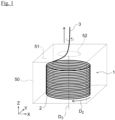
- the cable bundle 1 When installing the cable 2, for example, the cable bundle 1 is transported to the installation site while being housed in the container 50 as shown in FIG. 1 .
- the container 50 has a box-like shape, and the container 50 has an opening 52 formed in its upper plane. Then, the cable 2 is sequentially send out from one end 3 to the outside of the container 50 through the opening 52, the cable 2 is supplied to the installation site.
- the cable bundle 1 is disposed in the container 50 in a posture (i.e., a "vertical posture") in which the axial D 3 of the cable bundle 1 is substantially parallel to the vertical direction (Z direction in the drawing).
- the container 50 is formed using a cardboard made of paper.
- the container 50 may be formed using a plastic cardboard made of a resin material such as polypropylene (PP), or the container 50 may be formed using a metallic box.
- the unit bundle 10A includes a first loop 20A and a second loop 30A.
- the first and second loops 20A and 30A have substantially the same diameter in the present embodiment, the diameters of the first and second loops 20A and 30A may be different from each other.
- the first loop 20A is formed by winding the cable 2 in a "normal winding”.
- the second loop 30A is formed by winding the cable 2 in a "reverse winding”.
- the two loops 20A and 30A are stacked so that the second loop 30A is disposed on the first loop 20A in the vertical direction (Z direction in the figure).
- the winding method of the first loop 20A is the "normal winding".
- the winding method of the second loop 30A is the "reverse winding”.
- the stacking direction D 3 (Z direction in the drawing) of the two loops 20A and 30A corresponds to an example of the "second direction" in the aspect of the present invention.
- the unit bundle 10B is stacked on the unit bundle 10A.
- the unit bundles 10A and 10B are connected via the intermediate part 40A of the cable 2.
- the intermediate part 40A is the part of the cable 2 that is interposed between the unit bundles 10A and 10B, and the intermediate part 40A is wound in the circumferential direction D 1 of the cable bundle 1.
- the connecting part 12A of the unit bundle 10A and the connecting part 12B of the unit bundle 10B are located at different positions within the range of 120 degrees to 240 degrees in the circumferential direction D 1 of the cable bundle 1 (120° ⁇ 1 ⁇ 240°).
- the length L 3 of the intermediate part 40B may be 1/4 to 3/4 of the circumferential length L 4 of the first loop 20B (L 4 ⁇ 1/4 ⁇ L 2 ⁇ L 4 ⁇ 3/4).
- the connecting part 12B of the unit bundle 10B and the connecting part 12C of the unit bundle 10C are located at different positions within the range of 90 degrees to 270 degrees in the circumferential direction D 1 of the cable bundle 1 (90° ⁇ 2 ⁇ 270°).
- the length L 3 of the intermediate part 40B may be 1/3 to 2/3 of the circumferential length L 4 of the first loop 20B (L 4 ⁇ 1/3 ⁇ L 3 ⁇ L 4 ⁇ 2/3).
- the connecting part 12B of the unit bundle 10B and the connecting part 12C of the unit bundle 10C are located at different positions within the range of 120 degrees to 240 degrees in the circumferential direction D 1 of the cable bundle 1 (120° ⁇ 2 ⁇ 240°).
- the twist 13 is applied to the vicinity of the end part 4 of the unit bundle 10A on the winding start side.
- the twist 13 is applied to the cable 2 by twisting the cable 2 by one rotation in the direction opposite to a twist caused by the intermediate parts 40A and 40B when the cable 2 is unwound from the cable bundle 1.
- the twist 13 is applied to the cable 2 by twisting the cable 2 one rotation in the direction opposite to the winding direction D 2 (refer to FIG. 1 ) of the cable bundle 1 when viewing the cable bundle 1 from the pull-out side (end part 3 side) of the cable 2.
- the one rotation twist 13 of the unit bundle 10 can cancel the twist caused by the two intermediate parts 40A and 40B corresponding to one circumference of the cable bundle 1 when the cable 2 is unwound from the cable bundle 1.
- the position where the twist 13 is applied in the cable bundle 1 is not limited to the vicinity of the end part of the unit bundle.
- the twist 13 may be applied to any position in the unit bundle, or the twist 13 may be applied to the intermediate part connecting the unit bundles.
- the total rotation number R of all the twists 13 applied to the entire cable bundle 1 is preferably equal to or less than the value obtained by dividing the total L t of the lengths of all the intermediate parts 40A, 40B, ... of the cable bundle 1 by the average circumferential length L 0 of the cable bundle 1 (R ⁇ L t /L 0 ), and the rotation number R is more preferably equal to the value obtained by dividing the total Lt of the lengths of the intermediate parts 40A, 40B, ...
- the figure-8 shaped third loop 11C is folded at the connecting part 12C, and the second loop 30C is stacked on the first loop 20C to form the unit bundle 10C.
- the upper unit bundle functions as a weight for the loops of the lower unit bundle (for example, the loops 20A and 30A of the unit bundle 10A)
- the lifting of the loops for example, the loops 20A and 30A of the unit bundle 10A
- the start point 21 of the first loop 20 is located on the lower side with respect to the end point 22 of the first loop 20.
- the end point 32 of the second loop 30 is located on the lower side with respect to the start point 31 of the second loop 30 and the start point 21 of the first loop 20, and the part 8 of the cable 2 (part 8 on the end part 4 side from the start point 21 of the first loop 20 in the cable 2) passes through the second loop 30.
- the length of the intermediate part 40A has a length corresponding to the center angle ⁇ 5 in the circumferential direction D 1 of the cable bundle 1C.
- the holding device 61 may include a rotating device 612 that rotates the drum 611 about the rotational axis RA 2 substantially parallel to the direction D 4 in which the cable 2 is send out from the drum 611.
- the rotational axis RA 2 is also an axis substantially perpendicular to the rotational axis RA 1 of the drum 611.
- the rotational axis RA 2 corresponds to an example of the "second axis" in the aspect of the present invention.
Landscapes
- Engineering & Computer Science (AREA)
- Textile Engineering (AREA)
- Storage Of Web-Like Or Filamentary Materials (AREA)
- Insulated Conductors (AREA)
- Details Of Indoor Wiring (AREA)
Abstract
Description
- The present invention relates to a cable bundle, a method of manufacturing the cable bundle, and a cable bundle manufacturing apparatus.
- For designated countries that are permitted to be incorporated by reference in the literature, the contents of Patent Application No.
2022-187748 filed with Japan Patent Office on November 24, 2022 - As a method of winding a cable, a so-called "figure-8 (figure-eight) winding" is known, in which the cable is wound while forming loops by twisting the cable alternately clockwise and counterclockwise (for example, refer to Patent Document 1). In the "figure-8 winding", when the cable is extended by unwinding the first and second loops, no twist occurs in the cable because the helical twist generated when unwinding the first loop (the second loop) cancels the twist applied when making the second loop (the first loop).
- PATENT DOCUMENT 1:
JP 2017-5840 A1 - When the cable is continuously wound in the "figure-8 winding" described above, the intersections of the cable overlap in the winding direction of the cable. For this reason, if the cable has high bending rigidity, a loop being to be unwound later may lift up when the cable is unwound from the cable bundle, and the cable may be tangled and kinking may be caused in the cable. In particular, this phenomenon tends to occur frequently when the cable bundle is housed in a container and the cable is pulled out from the opening of the container.
- The problem to be solved by the present invention is to provide a cable bundle, a method of manufacturing the cable bundle, and a cable bundle manufacturing apparatus capable of suppressing the lifting of the loop.
-
- [1] An
aspect 1 of the present invention is a cable bundle comprising a cable that is wound, the cable bundle comprising unit bundles stacked in a second direction perpendicular to a first direction that is a circumferential direction of the cable bundle, wherein each of the unit bundles comprises a first loop and a second loop that are stacked in the second direction, the first loop and the second loop are connected via a connecting part so that a figure-8 shaped loop including the first loop and the second loop is formed when each of the unit bundles is opened, connecting parts of the unit bundles adjacent in the second direction are located at different positions in the first direction, and each of the connecting parts is the connecting part. - [2] An
aspect 2 of the present invention may be the cable bundle of theaspect 1, wherein the connecting parts of the unit bundles adjacent in the second direction may be located at different positions within a range of 90 degrees to 270 degrees in the first direction. - [3] An
aspect 3 of the present invention may be the cable bundle of theaspect - [4] An
aspect 4 of the present invention may be the cable bundle of any one of theaspects 1 to 3, comprising an intermediate part which is interposed between the unit bundles and connects the unit bundles, wherein the intermediate part may be wound in the first direction so that the connecting parts of the unit bundles adjacent in the second direction are located at different positions in the first direction. - [5] An
aspect 5 of the present invention may be the cable bundle of theaspect 4, wherein the intermediate parts may be wound in the first direction so that the connecting parts of the unit bundles adjacent in the second direction are located at different positions within a range of 90 degrees to 270 degrees in the first direction. - [6] An
aspect 6 of the present invention may be the cable bundle of theaspect - [7] An
aspect 7 of the present invention may be the cable bundle of any one of theaspects 1 to 6, wherein the unit bundles may include: a first unit bundle; a second unit bundle stacked on the first unit bundle; and a third unit bundle stacked on the second unit bundle, the cable bundle may comprise: a first intermediate part that is interposed between the first unit bundle and the second unit bundle and connects the first unit bundle and the second unit bundle; and a second intermediate part that is interposed between the second unit bundle and the third unit bundle and connects the second unit bundle and the third unit bundle, the first intermediate part and the second intermediate part may be wound in the first direction, and the first intermediate part and the second intermediate part may be located at different positions in the first direction. - [8] An
aspect 8 of the present invention may be the cable bundle of any one of theaspects 1 to 7, comprising an intermediate part which is interposed between the unit bundles, connects the unit bundles and is wound in the first direction, wherein the cable may have an opposite twist opposite to a twist caused by the intermediate part when the cable is unwound. - [9] An aspect 9 of the present invention may be the cable bundle of the
aspect 8, wherein the rotation number of opposite twists that the cable has may be less than or equal to a value obtained by dividing a total length of intermediate parts by an average circumferential length of the cable bundle, each of the intermediate parts may be the intermediate part, and each of the opposite twists may be the opposite twist. - [10] An aspect 10 of the present invention may be the cable bundle of any one of the
aspects 1 to 7, wherein the connecting part may be a part of the cable between a first intersection of the first loop and a second intersection of the second loop, and the connecting part may be wound in the first direction. - [11] An
aspect 11 of the present invention may be the cable bundle of the aspect 10, wherein the connecting parts included in the unit bundles adjacent in the second direction and an intermediate part connecting the unit bundles may form one circumference in the first direction. - [12] An aspect 12 of the present invention may be the cable bundle of any one of the
aspects 1 to 11, wherein the first loop may be formed by winding the cable in a normal winding or a reverse winding opposite to the normal winding, and the second loop may be formed by winding the cable in the reverse winding or the normal winding. - [13] An
aspect 13 of the present invention may be the cable bundle of any one of theaspects 1 to 12, wherein the unit bundles may be formed so that no twist due to the unit bundles occurs in the cable when the cable is unwound. - [14] An aspect 14 of the present invention is a method of manufacturing a cable bundle comprising a cable that is wound, the method comprising: a first step of forming unit bundles each of which comprises a first loop and a second loop that are connected via a connecting part and are stacked; and a second step of stacking the unit bundles so that connecting parts are located at different positions in a first direction that is a circumferential direction of the cable bundle, each of the connecting parts being the connecting part, wherein the first loop and the second loop are connected via the connecting part so that a figure-8 shaped loop including the first loop and the second loop is formed when each of the unit bundles is opened.
- [15] An
aspect 15 of the present invention may be the method of manufacturing the cable bundle of the aspect 14, wherein the first step may comprise: forming third loops each of which comprises the first loop and the second loop connected via the connecting part by disposing the cable in a figure-8 shape; and forming the unit bundles by folding each of the third loops at the connecting part and stacking the first loop and the second loop. - [16] An aspect 16 of the present invention may be the method of manufacturing the cable bundle of the aspect 14, wherein the first step may comprise: forming the first loop by twisting the cable in a third direction; forming the second loop by twisting the cable in a fourth direction opposite to the third direction; and forming each of the unit bundles by stacking the first loop and the second loop.
- [17] An aspect 17 of the present invention may be the method of manufacturing the cable bundle of any one of the aspects 14 to 17, wherein the second step may comprise stacking the unit bundles so that the connecting parts of the unit bundles adjacent are located at different positions within a range of 90 degrees to 270 degrees in the first direction.
- [18] An aspect 18 of the present invention may be the method of manufacturing the cable bundle of any one of the aspects 14 to 17, wherein the cable bundle may comprise an intermediate part which is interposed between the unit bundles and connects the unit bundles, and the second step may comprise winding the intermediate part in the first direction so that the connecting parts of the unit bundles adjacent are located at different positions in the first direction.
- [19] An aspect 19 of the present invention may be the method of manufacturing the cable bundle of the aspect 18, wherein the second step may comprise winding the intermediate parts in the first direction so that the connecting parts of the unit bundles adjacent are located at different positions within a range of 90 degrees to 270 degrees in the first direction.
- [20] An
aspect 20 of the present invention may be the method of manufacturing the cable bundle of any one of the aspects 14 to 19, wherein the intermediate part may have a length of 1/4 to 3/4 of a circumference of the first loop or the second loop connected to the intermediate part. - [21] An aspect 21 of the present invention is a cable bundle manufacturing apparatus that manufactures a cable bundle comprising a cable that is wound, the cable bundle manufacturing apparatus comprising: a fixing device that fixes a movement of the cable in an axial direction at a fixed position on the cable; a sending device that sends out the cable toward the fixed position; a twisting device that forms a loop of the cable by twisting the cable sent out by the sending device; a first rotating device that has a placement surface on which the loop formed by the twisting device is placed and stacked and rotates the placement surface about a first axis substantially parallel to a normal direction of the placement surface.
- [22] An
aspect 22 of the present invention may be the cable bundle manufacturing apparatus of the aspect 21, wherein the twisting device may form a first loop by twisting the cable in a third direction and may form a second loop by twisting the cable in a fourth direction opposite to the third direction. - [23] An aspect 23 of the present invention may be the cable bundle manufacturing apparatus of the
aspect 21 or 22, comprising a second rotating device that rotates a drum that supplies the cable about a second axis that is substantially parallel to a direction in which the cable is sent out from the drum. - According to the present invention, since the connecting parts of the unit bundles adjacent in the second direction are located at different positions in the first direction, it is possible to suppress the lifting of the loop being to be unwound later. According to the present invention, since the first rotating device rotates the placement surface on which the loop of the cable is placed, it is possible to manufacture the cable bundle that includes the above-described connecting parts located at different positions in the first direction.
-
-
FIG. 1 is a perspective view showing a cable bundle in the first embodiment of the present invention. -
FIG. 2 is an enlarged side view of a part of the cable bundle shown inFIG. 1 . -
FIG. 3 (a) is a schematic plan view showing a position of a first intermediate part in the circumferential direction of the cable bundle, andFIG. 3 (b) is a schematic plan view showing a position of a second intermediate part in the circumferential direction of the cable bundle. -
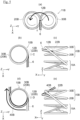
FIG. 4(a) to FIG. 4(e) are diagrams illustrating a method of forming a first unit bundle of the cable bundle in the first embodiment of the present invention. -
FIG. 5(a) to FIG. 5(e) are diagrams illustrating a method of forming a second unit bundle of the cable bundle in the first embodiment of the present invention. -
FIG. 6(a) to FIG. 6(e) are diagrams illustrating a method of forming a third unit bundle of the cable bundle in the first embodiment of the present invention. -
FIG. 7 is a perspective view showing a configuration of a figure-8 shaped loop when the unit bundle is opened in the second embodiment of the present invention. -
FIG. 8 is a side view showing a cable bundle in the second embodiment of the present invention and is a view corresponding toFIG. 2 . -
FIG. 9 is a developed view of a part of a cable bundle in the third embodiment of the present invention. -
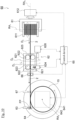
FIG. 10 is a diagram illustrating a cable bundle manufacturing apparatus in the third embodiment of the present invention. - Hereinafter, the embodiments of the present invention will be described with reference to the drawings.
-
FIG. 1 is a perspective view showing acable bundle 1 in the first embodiment of the present invention,FIG. 2 is an enlarged side view of a part of thecable bundle 1 shown inFIG. 1 .FIG. 3 (a) is a schematic plan view showing a position of a firstintermediate part 40A in the circumferential direction D1 of thecable bundle 1, andFIG. 3 (b) is a schematic plan view showing a position of a secondintermediate part 40B in the circumferential direction D1 of thecable bundle 1. - In
FIG. 1 , thecontainer 50 is shown transparently in order to facilitate understanding of the inside of thecontainer 50. InFIG. 2 , the white part in thecable 2 indicates the front side of thecable 2, the shaded part in thecable 2 indicates the rear side of thecable 2. Further, inFIG. 2 , the thick solid line parts in thecable 2 indicate theintermediate parts cable 2, the thick broken line parts in thecable 2 indicate the connectingparts cable 2. - As shown in
FIG. 1 , thecable bundle 1 in the present embodiment includes acable 2 that is wound in an annular shape (cylindrical shape, coil shape) in the winding direction D2, and thecable bundle 1 is formed by winding a singlecontinuous cable 2 using a winding method described later. Thecable bundle 1 has a so-called drumless structure that does not have a winding core such as a drum or a reel. Although an optical fiber cable can be exemplified as a specific example of thecable 2, thecable 2 is not particularly limited thereto. For example, a metal cable for power transmission, communication, or a combination of these may be used as thecable 2. Although thecable 2 of the present embodiment has no connection point between one end portion 3 (e.g., the end of the winding end side of the cable 2 (E end)) and the other end portion 4 (e.g., the end of the winding start side of the cable 2 (S end)) (seeFIG. 2 ), for example, a single continuous cable may be configured by connecting a plurality of cables with fusion or a connector or the like. - When installing the
cable 2, for example, thecable bundle 1 is transported to the installation site while being housed in thecontainer 50 as shown inFIG. 1 . Thecontainer 50 has a box-like shape, and thecontainer 50 has anopening 52 formed in its upper plane. Then, thecable 2 is sequentially send out from oneend 3 to the outside of thecontainer 50 through theopening 52, thecable 2 is supplied to the installation site. Thecable bundle 1 is disposed in thecontainer 50 in a posture (i.e., a "vertical posture") in which the axial D3 of thecable bundle 1 is substantially parallel to the vertical direction (Z direction in the drawing). Although not particularly limited, for example, thecontainer 50 is formed using a cardboard made of paper. For example, thecontainer 50 may be formed using a plastic cardboard made of a resin material such as polypropylene (PP), or thecontainer 50 may be formed using a metallic box. - As shown in
FIG. 2 , thecable bundle 1 includes unit bundles 10A, 10B, 10C, ... andintermediate parts cable 2 in a figure-8 shape to form two circular loops and folding the two loops, as will be described in more detail below. The unit bundles 10A, 10B, 10C, ... are stacked in the vertical direction (Z direction in the drawing). Further, each of theintermediate parts cable 2 that is interposed between the unit bundles 10A, 10B, 10C, ..... AlthoughFIG. 2 shows only threeunit bundles other end 4 side of thecable 2, thecable bundle 1 actually includes a large number of unit bundles. - The
unit bundle 10A includes afirst loop 20A and asecond loop 30A. Although the first andsecond loops second loops first loop 20A is formed by winding thecable 2 in a "normal winding". On the other hand, thesecond loop 30A is formed by winding thecable 2 in a "reverse winding". The twoloops second loop 30A is disposed on thefirst loop 20A in the vertical direction (Z direction in the figure). - Here, in the present embodiment, the "normal winding" is a winding method in which the
cable 2 is wound so that the start point of the loop is located on one side (for example, the lower side) with respect to the end point in the stacking direction of the two loops constituting the unit bundle. On the other hand, the "reverse winding" is a winding method in which thecable 2 is wound so that the start point of the loop is located on the other side (for example, the upper side) with respect to the end point in the stacking direction of the two loops. - Therefore, in the
first loop 20A of theunit bundle 10A, since thecable 2 is wound so that thestart point 21A is located on the lower side with respect to theend point 22A in the stacking direction D3 (Z direction in the drawing) of the twoloops first loop 20A is the "normal winding". On the other hand, in thesecond loop 30A of theunit bundle 10A, since thecable 2 is wound so that thestart point 31A is located on the upper side with respect to theend point 32A in the stacking direction D3 (Z direction in the drawing) of the twoloops second loop 30A is the "reverse winding". The stacking direction D3 (Z direction in the drawing) of the twoloops - Since the
bundle 10A is formed by the figure-8 (figure-eight) winding, the twoloops part 12A. In other words, the twoloops part 12A so that a figure-8 shapedloop 11A (seeFIG. 4(a) described later) including the first andsecond loops unit bundle 10A is opened. When theunit bundle 10A is opened (seeFIG. 4(a) ), thestart point 21A of thefirst loop 20A is located below theend point 22A of thefirst loop 20A, and thestart point 31A of thesecond loop 30A is also located below theend point 32A of thesecond loop 30A. By forming such the figure-8 shapedloop 11A, no twist due to theunit bundle 10A occurs in thecable 2 when thecable 2 is unwound. - Here, the
first loop 20A is defined by making thecable 2 cross at thestart point 21A and theend point 22A of thefirst loop 20A, and thesecond loop 30A is also defined by making thecable 2 cross at thestart point 31A and theend point 32A of thesecond loop 30A. Thus, when the first intersection defining thefirst loop 20A and the second intersection defining thesecond loop 30A overlap in the circumferential direction D1 of thecable bundle 1, the connectingpart 12A coincides with the first and second intersections in the circumferential direction D1. On the other hand, when the first and second intersections are located at different positions in the circumferential direction D1 of thecable bundle 1, the connectingpart 12A is the part of thecable 2 between the first and second intersections including the first and second intersections. Thus, the "figure-8 (figure-eight) shape" in the present embodiment includes the complete figure-8 shape in which the connectingpart 12A has no length, and also includes the shape in which the twoloops part 12A having a length. The "figure-8 (figure-eight)" in the present embodiment is the Arabic numeral "8". - The
unit bundle 10B includes afirst loop 20B formed by winding thecable 2 in the normal winding and asecond loop 30B formed by winding thecable 2 in the reverse winding. In thefirst loop 20B, since thecable 2 is wound so that thestart point 21B is located on the lower side with respect to theend point 22B in the stacking direction D3 (Z direction in the drawing) of the twoloops first loop 20B is the "normal winding". On the other hand, in thesecond loop 30B, since thecable 2 is wound so that thestart point 31B is located on the upper side with respect to theend point 32B in the stacking direction D3 (Z direction in the drawing) of the twoloops second loop 30B is the "reverse winding". - The two
loops second loop 30B is disposed on thefirst loop 20B in the vertical direction (Z direction in the drawing). Since thebundle 10B is also formed by the figure-8 (figure-eight) winding, the twoloops part 12B. In other words, the twoloops part 12B so that a figure-8 shapedloop 11B (seeFIG. 5(a) described later) including the first andsecond loops unit bundle 10B is opened. When theunit bundle 10B is opened (seeFIG. 5(a) ), thestart point 21B of thefirst loop 20B is located below theend point 22B of thefirst loop 20B, and thestart point 31B of thesecond loop 30B is also located below theend point 32B of thesecond loop 30B. By forming such the figure-8 shapedloop 11B, no twist due to theunit bundle 10B occurs in thecable 2 when thecable 2 is unwound. - The
unit bundle 10B is stacked on theunit bundle 10A. The unit bundles 10A and 10B are connected via theintermediate part 40A of thecable 2. Theintermediate part 40A is the part of thecable 2 that is interposed between the unit bundles 10A and 10B, and theintermediate part 40A is wound in the circumferential direction D1 of thecable bundle 1. - Although not particularly limited, in the present embodiment, as shown in
FIG. 3(a) , the length L1 of theintermediate part 40A is 1/2 of the circumferential length L2 of thesecond loop 30A of thelower unit bundle 10A to which theintermediate part 40A is connected (L1=1/2×L2), and the connectingpart 12A of theunit bundle 10A and the connectingpart 12B of theunit bundle 10B are located at different positions by 180 degrees in the circumferential direction D1 of the cable bundle 1 (θ1=180°). Therefore, the connectingparts cable bundle 1. The circumferential direction D1 of thecable bundle 1 corresponds to an example of the "first direction" in the aspect of the present invention. - The length L1 of the
intermediate part 40A may be 1/4 to 3/4 of the circumferential length L2 of thesecond loop 30A (L2×1/4≦L1≦L2×3/4). In this case, the connectingpart 12A of theunit bundle 10A and the connectingpart 12B of theunit bundle 10B are located at different positions within the range of 90 degrees to 270 degrees in the circumferential direction D1 of the cable bundle 1 (90°≦θ1≦270°). Alternatively, the length L1 of theintermediate part 40A may be 1/3 to 2/3 of the circumferential length L2 of thesecond loop 30A (L2×1/3≦L1≦L2×2/3). In this case, the connectingpart 12A of theunit bundle 10A and the connectingpart 12B of theunit bundle 10B are located at different positions within the range of 120 degrees to 240 degrees in the circumferential direction D1 of the cable bundle 1 (120°≦θ1≦240°). - As shown in
FIG. 2 , theunit bundle 10C also includes afirst loop 20C formed by winding thecable 2 in the normal winding and asecond loop 30C formed by winding thecable 2 in the reverse winding. The twoloops second loop 30C is disposed on thefirst loop 20C in the vertical direction (Z direction in the figure). Since thebundle 10C is also formed by the figure-8 (figure-eight) winding, the twoloops part 12C. In other words, the twoloops part 12C so that a figure-8 shapedloop 11C (seeFIG. 6(a) described later) including the first andsecond loops unit bundle 10C is opened. When theunit bundle 10C is opened (seeFIG. 6(a) ), thestart point 21C of thefirst loop 20C is located below theend point 22C of thefirst loop 20C, and thestart point 31C of thesecond loop 30C is also located below theend point 32C of thesecond loop 30C. By forming such the figure-8 shapedloop 11C, no twist due to theunit bundle 10C occurs in thecable 2 when thecable 2 is unwound. - The
unit bundle 10C is stacked on theunit bundle 10B. The unit bundles 10B and 10C are connected via theintermediate part 40B of thecable 2. Theintermediate part 40B is the part of thecable 2 that is interposed between the unit bundles 10B and 10C, and theintermediate part 40B is wound in the circumferential D1 of thecable bundle 1. - Although not particularly limited, in the present embodiment, as shown in
FIG. 3(b) , the length L3 of theintermediate part 40B is 1/2 of the circumferential length L4 of thefirst loop 20B of thelower unit bundle 10B to which theintermediate part 40B is connected (L3=1/2×L4), and the connectingpart 12B of theunit bundle 10B and the connectingpart 12C of theunit bundle 10C are located at different positions by 180 degrees in the circumferential direction D1 of the cable bundle 1 (θ2=180°). Therefore, the connectingparts cable bundle 1. Further, the above-describedintermediate part 40A and theintermediate part 40B are located at different positions in the circumferential D1 of thecable bundle 1. - The length L3 of the
intermediate part 40B may be 1/4 to 3/4 of the circumferential length L4 of thefirst loop 20B (L4×1/4≦L2≦L4×3/4). In this case, the connectingpart 12B of theunit bundle 10B and the connectingpart 12C of theunit bundle 10C are located at different positions within the range of 90 degrees to 270 degrees in the circumferential direction D1 of the cable bundle 1 (90°≦θ2≦270°). Alternatively, the length L3 of theintermediate part 40B may be 1/3 to 2/3 of the circumferential length L4 of thefirst loop 20B (L4×1/3≦L3≦L4×2/3). In this case, the connectingpart 12B of theunit bundle 10B and the connectingpart 12C of theunit bundle 10C are located at different positions within the range of 120 degrees to 240 degrees in the circumferential direction D1 of the cable bundle 1 (120°≦θ2≦240°). - As shown in
FIG. 2 , in thecable bundle 1 of the present embodiment, thetwist 13 is applied to the vicinity of theend part 4 of theunit bundle 10A on the winding start side. Thetwist 13 is applied to thecable 2 by twisting thecable 2 by one rotation in the direction opposite to a twist caused by theintermediate parts cable 2 is unwound from thecable bundle 1. In other words, thetwist 13 is applied to thecable 2 by twisting thecable 2 one rotation in the direction opposite to the winding direction D2 (refer toFIG. 1 ) of thecable bundle 1 when viewing thecable bundle 1 from the pull-out side (endpart 3 side) of thecable 2. The onerotation twist 13 of the unit bundle 10 can cancel the twist caused by the twointermediate parts cable bundle 1 when thecable 2 is unwound from thecable bundle 1. - Although not particularly shown, the upper unit bundles above the
unit bundle 10C ofFIG. 2 among the unit bundles are configured by alternately repeating the above-describedunit bundle 10B and theunit bundle 10C (hereinafter simply referred to as "unit bundle 10B'" and "unit bundle 10C'"). The unit bundles 10B' and 10C' are connected via the above-describedintermediate part 40B, and theconnection parts cable bundle 1. - The
unit bundle 10C shown inFIG. 2 (orunit bundle 10C') and theunit bundle 10B' are connected via theintermediate part 40C. Similar to the above-describedintermediate parts intermediate part 40C has a length that is 1/2 of the circumferential length of thefirst loop 20C of thelower unit bundle 10C to which theintermediate part 40C is connected. Therefore, the connectingparts cable bundle 1. - Further, in the upper unit bundles above the
unit bundle 10C ofFIG. 2 among the unit bundles, one rotation oftwist 13 is applied to the two unit bundles 10B' and 10C'. - The position where the
twist 13 is applied in thecable bundle 1 is not limited to the vicinity of the end part of the unit bundle. For example, thetwist 13 may be applied to any position in the unit bundle, or thetwist 13 may be applied to the intermediate part connecting the unit bundles. At this time, the total rotation number R of all thetwists 13 applied to theentire cable bundle 1 is preferably equal to or less than the value obtained by dividing the total Lt of the lengths of all theintermediate parts cable bundle 1 by the average circumferential length L0 of the cable bundle 1 (R≦Lt/L0), and the rotation number R is more preferably equal to the value obtained by dividing the total Lt of the lengths of theintermediate parts intermediate parts cable bundle 1 can be canceled. The average circumferential length L0 of thecable bundle 1 is a value obtained by dividing the total length of thecable 2 by the winding number of thecable 2. - Hereinafter, the method of manufacturing the above-described
cable bundle 1 will be described with reference toFIG. 4(a) to FIG. 6(e) .FIG. 4(a) to FIG. 4(e) are diagrams illustrating the method of forming thefirst unit bundle 10A of thecable bundle 1 in the first embodiment of the present invention,FIG. 5(a) to FIG. 5(e) are diagrams illustrating the method of forming thesecond unit bundle 10B of thecable bundle 1 in the first embodiment of the present invention, andFIG. 6(a) to FIG. 6(e) are diagrams illustrating the method of forming thethird unit bundle 10C of thecable bundle 1 in the first embodiment of the present invention. -
FIG. 4(c) is the diagram of theunit bundle 10A viewed from the direction A inFIG. 4(b), and FIG. 4(e) is the diagram of theunit bundle 10A viewed from the direction B inFIG. 4(d) . Similarly,FIG. 5(c) is the diagram of theunit bundle 10B viewed from the direction C inFIG. 5(b), and FIG. 5(e) is the diagram of theunit bundle 10B viewed from the direction D inFIG. 5(d) . Similarly,FIG. 6(c) is the diagram of theunit bundle 10C viewed from the direction E inFIG. 6(b), and FIG. 6(e) is the diagram of theunit bundle 10C viewed from the direction F inFIG. 6(d) . - First, as shown in
FIG. 4(a) , the figure-8 shapedloop 11A is formed by disposing thecable 2 in the figure-8 shape. Thethird loop 11A includes the first andsecond loops part 12A. At this time, in thefirst loop 20A, the winding method of thefirst loop 20A is set to the "normal winding" by winding thecable 2 so that thestart point 21A is located on the lower side with respect to theend point 22A. On the other hand, even in thesecond loop 30A, thecable 2 is wound so that thestart point 31A is located on the lower side with respect to theend point 32A. When thesecond loop 30A is reversed thereafter, the winding method of thesecond loop 30A becomes the "reverse winding". - Further, when the
cable 2 is disposed in the figure-8 shape, thetwist 13 is formed in the vicinity of theend part 4 of thecable 2 in thefirst loop 20A. Thetwist 13 is applied to thecable 2 by twisting thecable 2 one rotation in the direction opposite to the winding direction D2 (refer toFIG. 1 ) of thecable bundle 1 when viewing thecable bundle 1 from the pull-out side (endpart 3 side) of thecable 2. For example, in the example shown inFIG. 1 , when thecable bundle 1 is viewed from the pull-out side (endpart 3 side) of thecable 2, since the winding direction D2 of thecable bundle 1 is clockwise, thetwist 13 that is counterclockwise is applied to thecable 2. - Next, as shown in
FIG. 4(b) and FIG. 4(c) , the figure-8 shapedthird loop 11A is folded at the connectingpart 12A, and thesecond loop 30A is stacked on thefirst loop 20A to form theunit bundle 10A. - Next, as shown in
FIG. 4(d) and FIG. 4(e) , thepart 5 of the cable 2 (part 5 on theend part 3 side from theend point 32A of thesecond loop 30A in the cable 2) is wound by 180 degrees in the circumferential direction D1 of thecable bundle 1. Thepart 5 of thecable 2 corresponds to theintermediate part 40A between the unit bundles 10A and 10B. - Next, as shown in
FIG. 5(a) , the figure-8 shapedthird loop 11B is formed by disposing the part of thecable 2 following thepart 5 in the figure-8 shape. Thethird loop 11B includes the first andsecond loops part 12B. At this time, in thefirst loop 20B, the winding method of thefirst loop 20B is set to the "normal winding" by winding thecable 2 so that thestart point 21B is located on the lower side with respect to theend point 22B. On the other hand, even in thesecond loop 30B, thecable 2 is wound so that thestart point 31B is located on the lower side with respect to theend point 32B. When thesecond loop 30B is reversed thereafter, the winding method of thesecond loop 30B becomes the "reverse winding". Thetwist 13 is not applied to thethird loop 11B. - In the
third loop 11B of the second stage, thefirst loop 20B and thesecond loop 30B are reverse compared to the positional relation of the first andsecond loops third loop 11A of the first stage. That is, in thethird loop 11A of the first stage shown inFIG. 4(a) , thefirst loop 20A is located on the right side with respect to thesecond loop 30A, whereas in thethird loop 11B of the second stage shown inFIG. 5(a) , thefirst loop 20B is located on the left side with respect to thesecond loop 30B. - Next, as shown in
FIG. 5(b) and FIG. 5(c) , the figure-8 shapedthird loop 11B is folded at the connectingpart 12B, and thesecond loop 30B is stacked on thefirst loop 20B to form theunit bundle 10B. - Next, as shown in
FIG. 5(d) and FIG. 5(e) , thepart 6 of the cable 2 (part 6 on theend part 3 side from theend point 22B of thefirst loop 20B in the cable 2) is wound by 180 degrees in the circumferential direction D1 of thecable bundle 1. Thepart 6 of thecable 2 corresponds to theintermediate part 40B between the unit bundles 10B and 10C. - Next, as shown in
FIG. 6(a) , the figure-8 shapedthird loop 11C is formed by disposing the part of thecable 2 following thepart 6 in the figure-8 shape. Thethird loop 11C includes the first andsecond loops part 12C. At this time, in thefirst loop 20C, the winding method of thefirst loop 20C is set to the "normal winding" by winding thecable 2 so that thestart point 21C is located on the lower side with respect to theend point 22C. On the other hand, even in thesecond loop 30C, thecable 2 is wound so that thestart point 31C is located on the lower side with respect to theend point 32C. When thesecond loop 30C is reversed thereafter, the winding method of thesecond loop 30C becomes the "reverse winding". Thetwist 13 is also not applied to thethird loop 11C. - In the
third loop 11B of the second stage, thefirst loop 20C and thesecond loop 30C are reverse compared to the positional relation of the first andsecond loops third loop 11B of the second stage. That is, in thethird loop 11B of the second stage shown inFIG. 5(a) , thefirst loop 20B is located on the left side with respect to thesecond loop 30B, whereas in thethird loop 11C of the third stage shown inFIG. 6(a) , thefirst loop 20C is located on the right side with respect to thesecond loop 30C. - Next, as shown in
FIG. 6(b) and FIG. 6(c) , the figure-8 shapedthird loop 11C is folded at the connectingpart 12C, and thesecond loop 30C is stacked on thefirst loop 20C to form theunit bundle 10C. - Next, as shown in
FIG. 6(d) and FIG. 6(e) , thepart 7 of the cable 2 (part 7 on theend part 3 side from theend point 22C of thefirst loop 20C in the cable 2) is wound by 180 degrees in the circumferential direction D1 of thecable bundle 1. Thepart 7 of thecable 2 corresponds to theintermediate part 40C between theunit bundle 10C and the next unit bundle (above-describedunit bundle 10B'). - Thereafter, the
cable bundle 1 is formed by alternately forming the unit bundle and the intermediate part in the same manner as described above. As described above, the upper unit bundles above theunit bundle 10C ofFIG. 2 among the unit bundles are configured by alternately repeating theunit bundle 10B' andunit bundle 10C'. Theunit bundle 10B' and theunit bundle 10C' are connected via the above-describedintermediate part 40B of thecable 2. Further, theunit bundle 10C' and theunit bundle 10B' are connected via the above-describedintermediate part 40C. - In the above-described manufacturing method, although forming and stacking unit bundles are repeated in order from the bottom, the manufacturing method is not particularly limited to this. For example, all of the unit bundles may be stacked after forming all of the unit bundles. Alternatively, all of the unit bundles may be formed by folding the third loops after forming all of the third loops, and then all of the unit bundles may be stacked. Alternatively, the unit bundle may be formed without undergoing the open state in the figure-8 shape.
- As described above, in the present embodiment, the connecting parts (for example, the connecting
parts cable bundle 1. For this reason, since the upper unit bundle (for example, theunit bundle 10B) functions as a weight for the loops of the lower unit bundle (for example, theloops unit bundle 10A), it is possible to suppress the lifting of the loops (for example, theloops unit bundle 10A) being to be unwound later and to prevent thecable 2 from being tangled. - The configuration of the figure-8 shaped loop when the unit bundle is opened is not limited to the above-described configuration as long as no twist due to the unit bundle occurs in the cable when the cable is unwound. For example, it may be the figure-8 shaped
loop 11 having the configuration as shown inFIG. 7. FIG. 7 is a perspective view showing the configuration of the figure-8 shapedloop 11 when the unit bundle 10 is opened in the second embodiment of the present invention. - In the example shown in
FIG. 7 , when the unit bundle 10 is opened, the start point 21 of thefirst loop 20 is located on the lower side with respect to theend point 22 of thefirst loop 20. Further, in the example shown inFIG. 7 , when the unit bundle 10 is opened, theend point 32 of the second loop 30 is located on the lower side with respect to thestart point 31 of the second loop 30 and the start point 21 of thefirst loop 20, and thepart 8 of the cable 2 (part 8 on theend part 4 side from the start point 21 of thefirst loop 20 in the cable 2) passes through the second loop 30. By forming such the figure-8 shapedloop 11, no twist due to the unit bundle 10 occurs in thecable 2 when thecable 2 is unwound. - When the unit bundle 10 shown in
FIG. 7 is used as unit bundles 10B and 10C, acable bundle 1B shown inFIG. 8 is formed. Regarding theunit bundle 10B of thecable bundle 1B shown inFIG. 8 , in thefirst loop 20B, since thecable 2 is wound so that thestart point 21B is located on the upper side with respect to theend point 22B in the stacking direction D3 (Z direction in the drawing) of the twoloops first loop 20B is the "reverse winding". On the other hand, in thesecond loop 30B as well, since thecable 2 is wound so that thestart point 31B is located on the upper side with respect to theend point 32B in the stacking direction D3 (Z direction in the drawing) of the twoloops second loop 30B is the "reverse winding". That is, the winding method of both of the first andsecond loops unit bundle 10C of thecable bundle 1B shown inFIG. 8 , the winding method of both of the first andsecond loops - As described above, the connecting part of the unit bundle may have a length. A cable-
bundle 1C in the third embodiment of the present invention will be described with reference toFIG. 9. FIG. 9 is a developed view of a part of acable bundle 1C in the third embodiment of the present invention. - As shown in
FIG. 9 , thecable bundle 1C includes unit bundles 10A, 10B, ... andintermediate parts cable bundle 1C is formed by twisting thecable 2 to from the individual loops in order and stacking the loops in order. AlthoughFIG. 9 shows only twounit bundles end part 4 side of thecable 2, thecable bundle 1C actually includes a large number of unit bundles. Further, althoughFIG.9 shows a state in which the unit bundles 10A and 10B are opened becauseFIG. 9 is a developed view of thecable bundle 1C, the unit bundles 10A, 10B, ... are actually stacked in the vertical direction (Z direction in the drawing). - The
unit bundle 10A includes afirst loop 20A and asecond loop 30A. Since thefirst loop 20A is formed by winding thecable 2 so that thestart point 21A is located on the upper side with respect to theend point 22A, the winding method of thefirst loop 20A is the "reverse winding". On the other hand, since thesecond loop 30A is formed by winding thecable 2 so that thestart point 31A is located on the lower side with respect to theend point 32A, the winding method of thesecond loop 30A is the "normal winding". SinceFIG. 9 shows thecable bundle 1C in an open state, thestart point 31A of thesecond loop 30A is located on the upper side with respect to theend point 32A. The twoloops second loop 30A is disposed on thefirst loop 20A in the vertical direction (Z direction in the drawing). The twoloops part 12A so that a figure-8 shapedloop 11A including the first andsecond loops unit bundle 10A is opened. - In the present embodiment, the
intersection 23A of thefirst loop 20A (the point where thestart point 21A and theend point 22A intersect) does not coincide with theintersection 33A of thesecond loop 30A (the point where thestart point 31A and theend point 32A intersect), and theintersection 33A of thesecond loop 30A is separated from theintersection 23A of thefirst loop 20A. As described above, since the connectingpart 12A of theunit bundle 10A is the part of thecable 2 between theintersections second loops connection part 12A of the present embodiment has a predetermined length. The connectingpart 12A is wound in the circumferential direction D1 of thecable bundle 1C. The length of the connectingpart 12A has a length corresponding to the center angle θ3 in the circumferential direction D1 of thecable bundle 1C. Although not particularly limited, an example of the center angle θ3 is, for example, 120° (θ3=120°). The central angle defining the length of the connecting part is preferably 120° or less. - The
unit bundle 10B includes afirst loop 20B and asecond loop 30B. Since thefirst loop 20B is formed by winding thecable 2 so that thestart point 21B is located on the upper side with respect to theend point 22B, the winding method of thefirst loop 20B is the "reverse winding". Since thesecond loop 30B is also formed by winding thecable 2 so that thestart point 31B is located on the upper side with respect to theend point 32B, the winding method of thesecond loop 30B is also the "reverse winding". SinceFIG. 9 shows thecable bundle 1C in an open state, thestart point 21B of thefirst loop 20B is located on the lower side with respect to theend point 22B, and thestart point 31B of thesecond loop 30B is also located on the lower side with respect to theend point 32B. - The two
loops second loop 30B is disposed on thefirst loop 20B in the vertical direction (Z direction in the drawing). The twoloops part 12B so that a figure-8 shapedloop 11B including the first andsecond loops unit bundle 10B is opened. The winding method of thesecond loop 30B may be the "normal winding". - In the present embodiment, the
intersection 23B of thefirst loop 20B (the point where thestart point 21B and theend point 22B intersect) does not coincide with theintersection 33B of thesecond loop 30B (the point where thestart point 31B and theend point 32B intersect), and theintersection 33B of thesecond loop 30B is separated from theintersection 23B of thefirst loop 20B. As described above, since the connectingpart 12B of theunit bundle 10B is the part of thecable 2 between theintersections second loops connection part 12B of the present embodiment has a predetermined length. The connectingpart 12B is wound in the circumferential direction D1 of thecable bundle 1C. The length of the connectingpart 12B has a length corresponding to the center angle θ4 in the circumferential direction D1 of thecable bundle 1C. Although not particularly limited, an example of the center angle θ4 is, for example, 120° (θ4=120°). - The
unit bundle 10B is stacked on theunit bundle 10A. At this time, thestart point 31B and theend point 32B of thesecond loop 30B of theunit bundle 10B are located above thestart point 21A and theend point 22A of thefirst loop 20A of theunit bundle 10A. The unit bundles 10A and 10B are connected via theintermediate part 40A of thecable 2. Theintermediate part 40A is the part of thecable 2 that is interposed between theend point 32B of thesecond loop 30A of theunit bundle 10A and thestart point 21B of thefirst loop 20B of theunit bundle 10B, and theintermediate part 40A is wound in the circumferential direction D1 of thecable bundle 1C. The length of theintermediate part 40A has a length corresponding to the center angle θ5 in the circumferential direction D1 of thecable bundle 1C. Although not particularly limited, an example of the center angle θ5 is, for example, 120° (θ5=120°). - In the present embodiment, since each of the connecting
parts intermediate part 40A has a length corresponding to 120° in the circumferential direction D1 of thecable bundle 1C, these sum forms a loop of one circumference in the circumferential direction D1 of thecable bundle 1C. Whereas the winding method of the loop formed by the connectingparts intermediate part 40A and the winding method of thesecond loop 30B of theunit bundle 10A are the "normal winding", the winding method of thefirst loop 20A of theunit bundle 10A and the winding method of thefirst loop 20B of theunit bundle 10B are the "reverse winding", and the number of the loops of the "normal winding" and the number of the loops of the "reverse winding" are the same. Therefore, since there is no twist in these four loops, there is no need to form thetwist 13 described in the first embodiment in thecable bundle 1C. - In the above-described relationship in which the twist is zero, the total number of the first and second loops connected with the connecting part and the intermediate part is not particularly limited to the above as long as it is an odd number. In the above relationship in which the twist is zero, the winding method of each loop is not particularly limited to the above as long as the number of the loops of the "normal winding" and the number of the loops of the "reverse winding" are the same. The lengths of the connecting parts and the intermediate part forming the loop of one circumference in the circumferential direction D1 of the
cable bundle 1C may not be equal. - Next, the configuration of the
manufacturing apparatus 60 for manufacturing the above-mentionedcable bundle 1C will be described with reference toFIG. 10. FIG. 10 is a diagram illustrating the cablebundle manufacturing apparatus 60 in the third embodiment of the present invention. - As shown in
FIG. 10 , themanufacturing apparatus 60 of the present embodiment includes a holdingdevice 61, a twistingdevice 62, a fixingdevice 63, arotating device 64, and acontrol device 65. - The holding
device 61 holds adrum 611 around which thecable 2 is wound. Thedrum 611 is rotatably held by the holdingdevice 61 about the central axial RA1 of thedrum 611. In the present embodiment, although thedrum 611 is passively rotated as thecable 2 is pulled out by thecaterpillar 621 of the twistingdevice 62, the holdingdevice 61 may include a driving device that rotationally drives thedrum 611 about the rotational axis RA1 of thedrum 611. In this case, the driving device works in conjunction with thecaterpillar 621 of the twistingdevice 62 to positively send out thecable 2 from thedrum 611. - The holding
device 61 may include arotating device 612 that rotates thedrum 611 about the rotational axis RA2 substantially parallel to the direction D4 in which thecable 2 is send out from thedrum 611. Thus, when a twist occurs in the part of thecable 2 between thedrum 611 and the twistingdevice 62, it is possible to easily remove the twist from thecable 2. The rotational axis RA2 is also an axis substantially perpendicular to the rotational axis RA1 of thedrum 611. The rotational axis RA2 corresponds to an example of the "second axis" in the aspect of the present invention. - The twisting
device 62 includes a pair ofcaterpillars 621, aframe 625, and arotating device 626. Each of thecaterpillars 621 includes a pair ofpulleys 622, anendless belt 623 which is wound around thepulleys 622, and adriving device 624 that rotates thepulley 622. The pair ofcaterpillars 621 are arranged so that thebelts 623 are in close contact with each other, and thecable 2 supplied from thedrum 611 can be sandwiched between thebelts 623. Thedriving device 624 includes a motor, a gearbox and the like that rotate thepulley 622, and thecable 2 can be pulled out from thedrum 611 and thecable 2 can be pushed out from the twistingdevice 62 by driving thecaterpillar 621. The pair ofcaterpillars 621 corresponds to an example of the "sending device" in aspects of the present invention. - The pair of
caterpillars 621 is housed in theframe 625. Therotating device 626 includes a motor, a gearbox and the like that rotate theframe 625. Therotating device 626 is capable of twisting thecable 2 held between the pair ofcaterpillars 621 by rotating theframe 625 around the axial direction of thecable 2. Therotating device 626 is capable of rotating theframe 625 by 360° in one rotational direction D5 and is capable of rotating theframe 625 by 360° in the other rotational direction D6. The one rotational direction D5 corresponds to an example of the "third direction" in the aspect of the present invention, and the other rotational direction D6 corresponds to an example of the "fourth direction" in the aspect of the present invention. - The configuration of the twisting
device 62 is not particularly limited to the above as long as it includes a function of sending out thecable 2 and a function of twisting thecable 2. Although not particularly shown, for example, the twistingdevice 62 may include a gripping part that grips the cable and a moving part that moves the gripping part in the axial direction of thecable 2, and the gripping part may include rollers capable of twisting the cable. Although not particularly shown, the function of sending out thecable 2 and the function of twisting thecable 2 may be realized by mutually independent devices. - The fixing
device 63 is a device that fixes thecable 2 sent out from the twistingdevice 62. Although not particularly limited, a specific example of the fixingdevice 63 is a clamp that pinches and fixes the fixed position FP of thecable 2 by using an air cylinder or the like. The fixingdevice 63 fixes the movement of thecable 2 in the axial direction at the fixed position FP on thecable 2. The fixed position FP is the position on thecable 2 that is separated from the twistingdevice 62 by a predetermined distance. This predetermined distance is a distance that allows one loop 15 (for example, thefirst loop 20A) of thecable 2 to be formed between the fixed position FP and the twistingdevice 62. - When the
cable 2 is send out toward the fixed position FP by thecaterpillars 621 of the twistingdevice 62 and therotating device 626 of the twistingdevice 62 rotates in one rotational direction D5 in a state where the fixingdevice 63 fixes the fixing position FP on the cable, the "reverse winding" loop is formed. On the other hand, when the pair ofcaterpillars 621 rotate theframe 625 in the other rotational De, the "normal winding" loop is formed. - The
rotating device 64 includes a placement table 641 and adriving device 642. Theloops 15 formed by the twistingdevice 62 are placed on the placement table 641 and stacked. The placement table 641 includes a placement surface on which theloops 15 of thecable 2 are placed. Thedriving device 642 includes a motor, a gear box and the like that rotate the placement surface of the placement table 641. The driving device is capable of rotating the placement surface of the placement table 641 about a rotational axis RA3 substantially parallel to the normal direction of the placement table 641. The rotational axis RA3 corresponds to an example of the "first axis" in the aspect of the present embodiment. In the example shown inFIG. 10 , although thedriving device 642 rotates the placement surface of the placement table 641 only counterclockwise, the drivingdevice 642 may rotate the placement surface of the placement table 641 in both clockwise and counterclockwise directions. - The
control device 65 includes, for example, a computer. Although not particularly shown, the computer is an electronic computer including a CPU (processor), a main storage device (such as a RAM), a secondary storage device (such as a hard disk and a SSD), interfaces, and the like. Thecontrol device 65 is controllably connected to thedriving device 624 and therotating device 626 of the twistingdevice 62, the fixingdevice 63, and thedriving device 642 of therotating device 64. These controls are functionally realized, for example, by thecontrol device 65 executing a program. Thecontrol device 65 may be configured with a circuit board instead of the computer. - Next, a manufacturing process for manufacturing the
cable bundle 1C shown inFIG. 9 using themanufacturing device 60 described above will be described. - First, in a state where the
cable 2 is pulled out from the twistingdevice 62 to the fixingdevice 63, thecontrol device 65 transmits a control signal to the fixingdevice 63, and the fixingdevice 63 pinches the fixed position FP on thecable 2. Therefore, the movement of thecable 2 in the axial direction at the fixed position FP on thecable 2 is fixed by the fixingdevice 63. - Next, the
control device 65 transmits a control signal to thedriving device 624 of the twistingdevice 62, and thecaterpillars 621 send out thecable 2 from the twistingdevice 62 by a predetermined amount. This predetermined amount is a length corresponding to oneloop 15 of thecable 2 and is a value input to thecontrol device 65 in advance. - Next, the
control device 65 sends a control signal to therotating device 626 of the twistingdevice 62, and therotating device 626 rotates theframe 625 by 360° in one rotational direction D5 to twist thecable 2, therefore thefirst loop 20A of the "reverse winding" is formed. Thefirst loop 20A is placed on the placement table 641 of therotating device 64. The twistingdevice 62 may twist thecable 2 while sending out a predetermined amount of thecable 2. - Next, the
control device 65 transmits a control signal to the fixingdevice 63, and the fixingdevice 63 loosens the fixing of thecable 2 to release thecable 2. Next, thecontrol device 65 transmits control signals to thedriving device 642 of therotating device 64 and thedriving device 624 of the twistingdevice 62. As a result, the drivingdevice 642 rotates the placement surface of the placement table 641 by the center angle θ3, and simultaneously, thecaterpillars 621 sends out thecable 2 from the twistingdevice 62 by a predetermined amount. This predetermined amount is a length corresponding to the center angle θ3 in the circumferential direction D1 of thecable bundle 1C and is a value input to thecontrol device 65 in advance. Although not particularly limited, in the present embodiment, the center angle θ3 is 120° (θ3=120°). As a result, the connectingpart 12A of theunit bundle 10A in thecable bundle 1C is formed. - Next, the
second loop 30A of theunit bundle 10A is formed in the same manner as thefirst loop 20A described above. At this time, therotating device 626 rotates theframe 625 by 360° in other rotational direction D6 to twist thecable 2, therefore thesecond loop 30A of the "normal winding" is formed. Thesecond loop 30A is placed on the placement table 641 of therotating device 64 to form theunit bundle 10A. The twistingdevice 62 may twist thecable 2 while sending out a predetermined amount of thecable 2. - Next, the
control device 65 transmits a control signal to the fixingdevice 63, and the fixingdevice 63 loosens the fixing of thecable 2 to release thecable 2. Next, thecontrol device 65 transmits control signals to thedriving device 642 of therotating device 64 and thedriving device 624 of the twistingdevice 62. As a result, the drivingdevice 642 rotates the placement surface of the placement table 641 by the center angle θ4, and simultaneously, thecaterpillars 621 sends out thecable 2 from the twistingdevice 62 by a predetermined amount. This predetermined amount is a length corresponding to the center angle θ4 in the circumferential direction D1 of thecable bundle 1C and is a value input to thecontrol device 65 in advance. Although not particularly limited, in the present embodiment, the center angle θ4 is 120° (θ4=120°). As a result, theintermediate part 40A between the unit bundles 10A and 10B in thecable bundle 1C is formed. - Thereafter, the
cable bundle 1C is formed by alternately forming the unit bundle and the intermediate part in the same manner as described above. If a twist occurs in the part of thecable 2 between thedrum 611 and the twistingdevice 62, it is possible to remove the twist by rotating thedrum 611 using the above-describedrotating device 612. - As described above, in the
manufacturing apparatus 60 of the present embodiment, since thedriving device 642 of therotating device 64 rotates the placement surface of the placement table 641 on which theloops 15 of thecable 2 are placed, it is possible to manufacture thecable bundle 1C that includes the connectingparts - The
manufacturing apparatus 60 may include a measuringdevice 66 that measures the length of thecable 2 sent out by the twistingdevice 62. In this case, thecontrol device 65 may control thedriving device 624 of the twistingdevice 62 so that thecaterpillars 621 send out thecable 2 from the twistingdevice 62 by a predetermined amount based on the measurement result of the measuringdevice 66. Although not particularly limited, an encoder can be exemplified as a specific example of themeasurement device 66. Alternatively, the length of thecable 2 sent out from the twistingdevice 62 may be measured by the measuringdevice 66 to perform quality control of thecable bundle 1. - The
cable bundle 1 shown inFIG. 1 may be manufactured using themanufacturing apparatus 60 described above. In this case, as shown inFIG. 10 , themanufacturing apparatus 60 includes anadditional fixing device 67 in addition to the above-describedfixing device 63. Theadditional fixing device 67 has a configuration similar to that of the fixingdevice 63 described above. When forming each unit bundle, the fixingdevice 63 is used to form the first loop, and theadditional fixing device 67 is used to form the second loop. - It should be noted that the embodiment described above are described to facilitate understanding of the present disclosure and are not described to limit the present disclosure. It is therefore intended that the elements disclosed in the above embodiment include all design modifications and equivalents to fall within the technical scope of the present disclosure.
- For example, although the
cable bundle 1 has the drumless structure that does not have a winding core in the above-described embodiment, thecable bundle 1 is not particularly limited to this. Thecable bundle 1 may have a winding core, or thecable bundle 1 may be formed around the guide pin for sending out. - In the above-described embodiment, although the unit bundles 10A, 10B, 10C, ... are stacked in a direction (the stacking direction D3 of the unit bundles (Z direction in the drawing)) perpendicular to the radial direction, it is not limited to this. For example, the unit bundles having different diameters disposed on the same plane may be stacked in the stacking direction D3 by appropriately changing the size of the diameters of the loop included in the unit bundle. Alternatively, other unit bundles each of which has a diameter larger than the diameter of the unit bundle may be stacked in the stacking direction D3 on the outer side of the unit bundles stacked in the stacking direction D3 by appropriately changing the size of the diameters of the loop included in the unit bundle.
- The connecting parts of the unit bundles may be located at different positions in the circumferential direction D1 of the
cable bundle 1 by making the diameters of the unit bundles adjacent to the stacking direction D3 of the unit bundles different. The first intersection and the second intersection may be located at different positions in the circumferential direction D1 of thecable bundle 1 by making the diameters of the first and second loops of the unit bundle different. -
- 1, 1B, 1C ... Cable bundle
- 2 ... Cable
- 3, 4 ... End
- 10A, 10B, 10C ... Unit bundle
- 11A, 11B, 11C ... Figure-8 shaped loop
- 12A, 12B, 12C ... Connecting part
- 13 ... Twist
- 20A, 20B, 20C ... First loop
- 21A, 21B, 21C ... Start point
- 22A, 22B, 22C ... End point
- 23A, 23B ... Intersection
- 30A, 30B, 30C ... Second loop
- 31A, 31B, 31C ... Start point
- 32A, 32B, 32C ... End point
- 33A, 33B ... Intersection
- 40A, 40B ... Intermediate part
- 50 ... Container
- 51 ... Upper surface
- 52 ... Opening
- 60 ... Manufacturing apparatus
- 61 ... Holding device
- 611 ... Drum
- 612 ... Rotating device
- 62 ... Twisting device
- 621 ... Caterpillar
- 622 ... Pulley
- 623... Belt
- 624 ... Driving device
- 625 ... Frame
- 626 ... Rotating device
- 63 ... Fixing device
- 64... Rotating device
- 641 ... Placement table
- 642 ... Driving device
- 65 ... Control device
- 66 ... Measuring device
- 67 ... Fixing device
Claims (15)
- A cable bundle comprising a cable that is wound, the cable bundle comprising unit bundles stacked in a second direction perpendicular to a first direction that is a circumferential direction of the cable bundle, whereineach of the unit bundles comprises a first loop and a second loop that are stacked in the second direction,the first loop and the second loop are connected via a connecting part so that a figure-8 shaped loop including the first loop and the second loop is formed when each of the unit bundles is opened,connecting parts of the unit bundles adjacent in the second direction are located at different positions in the first direction, and each of the connecting parts is the connecting part.
- The cable bundle according to claim 1, comprising an intermediate part which is interposed between the unit bundles and connects the unit bundles, wherein
the intermediate part is wound in the first direction so that the connecting parts of the unit bundles adjacent in the second direction are located at different positions within a range of 90 degrees to 270 degrees in the first direction. - The cable bundle according to claim 1 or 2, wherein,the unit bundles include:a first unit bundle;a second unit bundle stacked on the first unit bundle; anda third unit bundle stacked on the second unit bundle,the cable bundle comprises:a first intermediate part that is interposed between the first unit bundle and the second unit bundle and connects the first unit bundle and the second unit bundle; anda second intermediate part that is interposed between the second unit bundle and the third unit bundle and connects the second unit bundle and the third unit bundle,the first intermediate part and the second intermediate part are wound in the first direction, andthe first intermediate part and the second intermediate part are located at different positions in the first direction.
- The cable bundle according to any one of claims 1 to 3, comprising an intermediate part which is interposed between the unit bundles, connects the unit bundles and is wound in the first direction, wherein
the cable has an opposite twist opposite to a twist caused by the intermediate part when the cable is unwound. - The cable bundle according to claim 4, wherein
the rotation number of opposite twists that the cable has is less than or equal to a value obtained by dividing a total length of intermediate parts by an average circumferential length of the cable bundle, each of the intermediate parts is the intermediate part, and each of the opposite twists is the opposite twist. - The cable bundle according to any one of claims 1 to 3, wherein
the connecting part is a part of the cable between a first intersection of the first loop and a second intersection of the second loop, and the connecting part is wound in the first direction. - The cable bundle according to claim 6, wherein
the connecting parts included in the unit bundles adjacent in the second direction and an intermediate part connecting the unit bundles form one circumference in the first direction. - The cable bundle according to any one of claims 1 to 7, whereinthe first loop is formed by winding the cable in a normal winding or a reverse winding opposite to the normal winding, andthe second loop is formed by winding the cable in the reverse winding or the normal winding.
- A method of manufacturing a cable bundle comprising a cable that is wound, the method comprising:a first step of forming unit bundles each of which comprises a first loop and a second loop that are connected via a connecting part and are stacked; anda second step of stacking the unit bundles so that connecting parts are located at different positions in a first direction that is a circumferential direction of the cable bundle, each of the connecting parts being the connecting part, whereinthe first loop and the second loop are connected via the connecting part so that a figure-8 shaped loop including the first loop and the second loop is formed when each of the unit bundles is opened.
- The method of manufacturing the cable bundle according to claim 9, wherein
the first step comprises:forming third loops each of which comprises the first loop and the second loop connected via the connecting part by disposing the cable in a figure-8 shape; andforming the unit bundles by folding each of the third loops at the connecting part and stacking the first loop and the second loop. - The method of manufacturing the cable bundle according to claim 9, wherein
the first step comprises:forming the first loop by twisting the cable in a third direction;forming the second loop by twisting the cable in a fourth direction opposite to the third direction; andforming each of the unit bundles by stacking the first loop and the second loop. - The method of manufacturing the cable bundle according to any one of claims 9 to 11, whereinthe cable bundle comprises an intermediate part which is interposed between the unit bundles and connects the unit bundles, andthe second step comprises winding the intermediate part in the first direction so that the connecting parts of the unit bundles adjacent are located at different positions within a range of 90 degrees to 270 degrees in the first direction.
- A cable bundle manufacturing apparatus that manufactures a cable bundle comprising a cable that is wound, the cable bundle manufacturing apparatus comprising:a fixing device that fixes a movement of the cable in an axial direction at a fixed position on the cable;a sending device that sends out the cable toward the fixed position;a twisting device that forms a loop of the cable by twisting the cable sent out by the sending device;a first rotating device that has a placement surface on which the loop formed by the twisting device is placed and stacked and rotates the placement surface about a first axis substantially parallel to a normal direction of the placement surface.
- The cable bundle manufacturing apparatus according to claim 13, wherein
the twisting device forms a first loop by twisting the cable in a third direction and forms a second loop by twisting the cable in a fourth direction opposite to the third direction. - The cable bundle manufacturing apparatus according to claim 13 or 14, comprising
a second rotating device that rotates a drum that supplies the cable about a second axis that is substantially parallel to a direction in which the cable is sent out from the drum.
Applications Claiming Priority (2)
| Application Number | Priority Date | Filing Date | Title |
|---|---|---|---|
| JP2022187748 | 2022-11-24 | ||
| PCT/JP2023/041683 WO2024111561A1 (en) | 2022-11-24 | 2023-11-20 | Cable bundle, cable bundle manufacturing method, and cable bundle manufacturing device |
Publications (2)
| Publication Number | Publication Date |
|---|---|
| EP4397611A1 true EP4397611A1 (en) | 2024-07-10 |
| EP4397611A4 EP4397611A4 (en) | 2025-03-19 |
Family
ID=91195597
Family Applications (1)
| Application Number | Title | Priority Date | Filing Date |
|---|---|---|---|
| EP23869322.0A Pending EP4397611A4 (en) | 2022-11-24 | 2023-11-20 | CABLE BUNDLE, CABLE BUNDLE MANUFACTURING METHOD AND CABLE BUNDLE MANUFACTURING APPARATUS |
Country Status (6)
| Country | Link |
|---|---|
| US (1) | US20260008647A1 (en) |
| EP (1) | EP4397611A4 (en) |
| JP (1) | JP7656149B2 (en) |
| CN (1) | CN120051429A (en) |
| TW (1) | TWI889024B (en) |
| WO (1) | WO2024111561A1 (en) |
Family Cites Families (14)
| Publication number | Priority date | Publication date | Assignee | Title |
|---|---|---|---|---|
| JPS52142926U (en) * | 1977-04-15 | 1977-10-29 | ||
| US5129514A (en) * | 1991-08-12 | 1992-07-14 | The Ensign-Bickford Company | Flexible cord winding and packaging configuration and method for making such package |
| US6145781A (en) * | 1997-07-10 | 2000-11-14 | Sumitomo Wiring Systems, Ltd. | Cable storage case permitting easy removal of cable stored therein |
| JP2001195933A (en) * | 2000-01-11 | 2001-07-19 | Hitachi Cable Ltd | Twist transmission device |
| JP2001310868A (en) * | 2000-04-28 | 2001-11-06 | Yazaki Corp | Flat cable bundle and cable bundle manufacturing equipment |
| US7330627B2 (en) * | 2006-04-07 | 2008-02-12 | Tyco Electronics Corporation | Coiled cable products and methods of forming the same |
| US20080296426A1 (en) * | 2007-06-01 | 2008-12-04 | Cairns James L | Apparatus and method for managing flexible lines |
| JP2013184795A (en) * | 2012-03-08 | 2013-09-19 | Fujikura Ltd | Optical cable wound body, optical cable package, optical cable winding method, and optical cable packaging method |
| US20140061356A1 (en) * | 2012-08-31 | 2014-03-06 | Adc Telecommunications, Inc. | Cable packing systems and methods |
| JP6484600B2 (en) * | 2016-10-12 | 2019-03-13 | 矢崎総業株式会社 | Twist wire manufacturing equipment |
| CN107472990A (en) * | 2017-09-30 | 2017-12-15 | 中国船舶重工集团公司第七0七研究所 | A kind of 8 word Winders and method of long cable twist prevention power accumulation |
| WO2020011334A1 (en) * | 2018-07-09 | 2020-01-16 | Prysmian S.P.A | Optical fiber installation kit and corresponding methods for using and manufacturing the same |
| US12269708B2 (en) * | 2020-12-24 | 2025-04-08 | Fujikura Ltd. | Housing unit and wound body |
| JP7748208B2 (en) | 2021-06-08 | 2025-10-02 | 日本エイアンドエル株式会社 | Thermoplastic resin composition and molded article |
-
2023
- 2023-11-20 US US19/131,147 patent/US20260008647A1/en active Pending
- 2023-11-20 EP EP23869322.0A patent/EP4397611A4/en active Pending
- 2023-11-20 CN CN202380073046.3A patent/CN120051429A/en active Pending
- 2023-11-20 JP JP2024519925A patent/JP7656149B2/en active Active
- 2023-11-20 WO PCT/JP2023/041683 patent/WO2024111561A1/en not_active Ceased
- 2023-11-23 TW TW112145328A patent/TWI889024B/en active
Also Published As
| Publication number | Publication date |
|---|---|
| TW202431740A (en) | 2024-08-01 |
| WO2024111561A1 (en) | 2024-05-30 |
| JPWO2024111561A1 (en) | 2024-05-30 |
| EP4397611A4 (en) | 2025-03-19 |
| JP7656149B2 (en) | 2025-04-02 |
| CN120051429A (en) | 2025-05-27 |
| TWI889024B (en) | 2025-07-01 |
| US20260008647A1 (en) | 2026-01-08 |
Similar Documents
| Publication | Publication Date | Title |
|---|---|---|
| US7330627B2 (en) | Coiled cable products and methods of forming the same | |
| CN107076954B (en) | Optical cable, method for manufacturing optical cable, and manufacturing device | |
| WO2015132996A1 (en) | Optical cable | |
| US10087027B2 (en) | Tape supplying method and tape supplying device | |
| WO2021117843A1 (en) | Optical fiber cable | |
| US12013586B2 (en) | Optical fiber cable | |
| WO2019124077A1 (en) | Optical fiber cable | |
| IL257870A (en) | Gimbal transmission cable management | |
| EP4397611A1 (en) | Cable bundle, cable bundle manufacturing method, and cable bundle manufacturing device | |
| US11592634B2 (en) | Optical fiber cable | |
| CA3272443A1 (en) | Cable bundle, method of manufacturing cable bundle, and cable bundle manufacturing apparatus | |
| EP3686639A1 (en) | Optical fiber cable | |
| US20220373753A1 (en) | Optical Fiber Cable | |
| CN118805108A (en) | Optical fiber cable and method for manufacturing the same | |
| JP5568071B2 (en) | Fiber optic cable | |
| EP4353445A1 (en) | Fiber winding device | |
| WO2022254724A1 (en) | Wiring module, frame for wiring module, and method for preparing wiring module | |
| WO2020246511A1 (en) | Optical fiber cable and manufacturing method for optical fiber cable | |
| KR102891688B1 (en) | Outer casing manufacturing equipment for control cable | |
| US20050034443A1 (en) | Optical fibers twinning apparatus and process | |
| EP3485307B1 (en) | Hauling grip for optical cables comprising pre-connectorized optical fibers | |
| TW202600417A (en) | Bundling device and bundling system | |
| JP2023114328A (en) | Optical fiber cable | |
| WO2023007881A1 (en) | Optical cable and optical cable manufacturing method | |
| CN114368642A (en) | Active yarn winding device and method for optical fiber bundle |
Legal Events
| Date | Code | Title | Description |
|---|---|---|---|
| STAA | Information on the status of an ep patent application or granted ep patent |
Free format text: STATUS: UNKNOWN |
|
| STAA | Information on the status of an ep patent application or granted ep patent |
Free format text: STATUS: THE INTERNATIONAL PUBLICATION HAS BEEN MADE |
|
| PUAI | Public reference made under article 153(3) epc to a published international application that has entered the european phase |
Free format text: ORIGINAL CODE: 0009012 |
|
| STAA | Information on the status of an ep patent application or granted ep patent |
Free format text: STATUS: REQUEST FOR EXAMINATION WAS MADE |
|
| 17P | Request for examination filed |
Effective date: 20240405 |
|
| AK | Designated contracting states |
Kind code of ref document: A1 Designated state(s): AL AT BE BG CH CY CZ DE DK EE ES FI FR GB GR HR HU IE IS IT LI LT LU LV MC ME MK MT NL NO PL PT RO RS SE SI SK SM TR |
|
| A4 | Supplementary search report drawn up and despatched |
Effective date: 20250213 |
|
| RIC1 | Information provided on ipc code assigned before grant |
Ipc: B65H 55/04 20060101ALI20250207BHEP Ipc: B65H 54/56 20060101ALI20250207BHEP Ipc: H02G 1/06 20060101ALI20250207BHEP Ipc: B65H 75/36 20060101AFI20250207BHEP |
|
| STAA | Information on the status of an ep patent application or granted ep patent |
Free format text: STATUS: EXAMINATION IS IN PROGRESS |
|
| 17Q | First examination report despatched |
Effective date: 20251126 |
|
| DAV | Request for validation of the european patent (deleted) | ||
| DAX | Request for extension of the european patent (deleted) | ||
| GRAP | Despatch of communication of intention to grant a patent |
Free format text: ORIGINAL CODE: EPIDOSNIGR1 |
|
| STAA | Information on the status of an ep patent application or granted ep patent |
Free format text: STATUS: GRANT OF PATENT IS INTENDED |
|
| INTG | Intention to grant announced |
Effective date: 20260320 |