EP4397600A1 - Liquefied hydrogen tank and method for designing same - Google Patents
Liquefied hydrogen tank and method for designing same Download PDFInfo
- Publication number
- EP4397600A1 EP4397600A1 EP22864201.3A EP22864201A EP4397600A1 EP 4397600 A1 EP4397600 A1 EP 4397600A1 EP 22864201 A EP22864201 A EP 22864201A EP 4397600 A1 EP4397600 A1 EP 4397600A1
- Authority
- EP
- European Patent Office
- Prior art keywords
- tank
- leakage prevention
- wall thickness
- liquefied hydrogen
- inner shell
- Prior art date
- Legal status (The legal status is an assumption and is not a legal conclusion. Google has not performed a legal analysis and makes no representation as to the accuracy of the status listed.)
- Pending
Links
Images

Classifications
-
- B—PERFORMING OPERATIONS; TRANSPORTING
- B63—SHIPS OR OTHER WATERBORNE VESSELS; RELATED EQUIPMENT
- B63B—SHIPS OR OTHER WATERBORNE VESSELS; EQUIPMENT FOR SHIPPING
- B63B25/00—Load-accommodating arrangements, e.g. stowing, trimming; Vessels characterised thereby
- B63B25/02—Load-accommodating arrangements, e.g. stowing, trimming; Vessels characterised thereby for bulk goods
- B63B25/08—Load-accommodating arrangements, e.g. stowing, trimming; Vessels characterised thereby for bulk goods fluid
- B63B25/12—Load-accommodating arrangements, e.g. stowing, trimming; Vessels characterised thereby for bulk goods fluid closed
- B63B25/16—Load-accommodating arrangements, e.g. stowing, trimming; Vessels characterised thereby for bulk goods fluid closed heat-insulated
-
- B—PERFORMING OPERATIONS; TRANSPORTING
- B63—SHIPS OR OTHER WATERBORNE VESSELS; RELATED EQUIPMENT
- B63B—SHIPS OR OTHER WATERBORNE VESSELS; EQUIPMENT FOR SHIPPING
- B63B71/00—Designing vessels; Predicting their performance
-
- F—MECHANICAL ENGINEERING; LIGHTING; HEATING; WEAPONS; BLASTING
- F17—STORING OR DISTRIBUTING GASES OR LIQUIDS
- F17C—VESSELS FOR CONTAINING OR STORING COMPRESSED, LIQUEFIED OR SOLIDIFIED GASES; FIXED-CAPACITY GAS-HOLDERS; FILLING VESSELS WITH, OR DISCHARGING FROM VESSELS, COMPRESSED, LIQUEFIED, OR SOLIDIFIED GASES
- F17C3/00—Vessels not under pressure
- F17C3/02—Vessels not under pressure with provision for thermal insulation
- F17C3/025—Bulk storage in barges or on ships
-
- G—PHYSICS
- G06—COMPUTING OR CALCULATING; COUNTING
- G06F—ELECTRIC DIGITAL DATA PROCESSING
- G06F30/00—Computer-aided design [CAD]
- G06F30/10—Geometric CAD
- G06F30/15—Vehicle, aircraft or watercraft design
-
- G—PHYSICS
- G06—COMPUTING OR CALCULATING; COUNTING
- G06F—ELECTRIC DIGITAL DATA PROCESSING
- G06F30/00—Computer-aided design [CAD]
- G06F30/10—Geometric CAD
- G06F30/18—Network design, e.g. design based on topological or interconnect aspects of utility systems, piping, heating ventilation air conditioning [HVAC] or cabling
-
- G—PHYSICS
- G06—COMPUTING OR CALCULATING; COUNTING
- G06F—ELECTRIC DIGITAL DATA PROCESSING
- G06F30/00—Computer-aided design [CAD]
- G06F30/20—Design optimisation, verification or simulation
-
- G—PHYSICS
- G06—COMPUTING OR CALCULATING; COUNTING
- G06F—ELECTRIC DIGITAL DATA PROCESSING
- G06F30/00—Computer-aided design [CAD]
- G06F30/20—Design optimisation, verification or simulation
- G06F30/23—Design optimisation, verification or simulation using finite element methods [FEM] or finite difference methods [FDM]
-
- F—MECHANICAL ENGINEERING; LIGHTING; HEATING; WEAPONS; BLASTING
- F17—STORING OR DISTRIBUTING GASES OR LIQUIDS
- F17C—VESSELS FOR CONTAINING OR STORING COMPRESSED, LIQUEFIED OR SOLIDIFIED GASES; FIXED-CAPACITY GAS-HOLDERS; FILLING VESSELS WITH, OR DISCHARGING FROM VESSELS, COMPRESSED, LIQUEFIED, OR SOLIDIFIED GASES
- F17C2201/00—Vessel construction, in particular geometry, arrangement or size
- F17C2201/01—Shape
- F17C2201/0128—Shape spherical or elliptical
-
- F—MECHANICAL ENGINEERING; LIGHTING; HEATING; WEAPONS; BLASTING
- F17—STORING OR DISTRIBUTING GASES OR LIQUIDS
- F17C—VESSELS FOR CONTAINING OR STORING COMPRESSED, LIQUEFIED OR SOLIDIFIED GASES; FIXED-CAPACITY GAS-HOLDERS; FILLING VESSELS WITH, OR DISCHARGING FROM VESSELS, COMPRESSED, LIQUEFIED, OR SOLIDIFIED GASES
- F17C2201/00—Vessel construction, in particular geometry, arrangement or size
- F17C2201/05—Size
- F17C2201/052—Size large (>1000 m3)
-
- F—MECHANICAL ENGINEERING; LIGHTING; HEATING; WEAPONS; BLASTING
- F17—STORING OR DISTRIBUTING GASES OR LIQUIDS
- F17C—VESSELS FOR CONTAINING OR STORING COMPRESSED, LIQUEFIED OR SOLIDIFIED GASES; FIXED-CAPACITY GAS-HOLDERS; FILLING VESSELS WITH, OR DISCHARGING FROM VESSELS, COMPRESSED, LIQUEFIED, OR SOLIDIFIED GASES
- F17C2203/00—Vessel construction, in particular walls or details thereof
- F17C2203/03—Thermal insulations
- F17C2203/0375—Thermal insulations by gas
-
- F—MECHANICAL ENGINEERING; LIGHTING; HEATING; WEAPONS; BLASTING
- F17—STORING OR DISTRIBUTING GASES OR LIQUIDS
- F17C—VESSELS FOR CONTAINING OR STORING COMPRESSED, LIQUEFIED OR SOLIDIFIED GASES; FIXED-CAPACITY GAS-HOLDERS; FILLING VESSELS WITH, OR DISCHARGING FROM VESSELS, COMPRESSED, LIQUEFIED, OR SOLIDIFIED GASES
- F17C2203/00—Vessel construction, in particular walls or details thereof
- F17C2203/03—Thermal insulations
- F17C2203/0391—Thermal insulations by vacuum
-
- F—MECHANICAL ENGINEERING; LIGHTING; HEATING; WEAPONS; BLASTING
- F17—STORING OR DISTRIBUTING GASES OR LIQUIDS
- F17C—VESSELS FOR CONTAINING OR STORING COMPRESSED, LIQUEFIED OR SOLIDIFIED GASES; FIXED-CAPACITY GAS-HOLDERS; FILLING VESSELS WITH, OR DISCHARGING FROM VESSELS, COMPRESSED, LIQUEFIED, OR SOLIDIFIED GASES
- F17C2203/00—Vessel construction, in particular walls or details thereof
- F17C2203/06—Materials for walls or layers thereof; Properties or structures of walls or their materials
- F17C2203/0602—Wall structures; Special features thereof
- F17C2203/0612—Wall structures
- F17C2203/0626—Multiple walls
- F17C2203/0629—Two walls
-
- F—MECHANICAL ENGINEERING; LIGHTING; HEATING; WEAPONS; BLASTING
- F17—STORING OR DISTRIBUTING GASES OR LIQUIDS
- F17C—VESSELS FOR CONTAINING OR STORING COMPRESSED, LIQUEFIED OR SOLIDIFIED GASES; FIXED-CAPACITY GAS-HOLDERS; FILLING VESSELS WITH, OR DISCHARGING FROM VESSELS, COMPRESSED, LIQUEFIED, OR SOLIDIFIED GASES
- F17C2203/00—Vessel construction, in particular walls or details thereof
- F17C2203/06—Materials for walls or layers thereof; Properties or structures of walls or their materials
- F17C2203/0602—Wall structures; Special features thereof
- F17C2203/0612—Wall structures
- F17C2203/0626—Multiple walls
- F17C2203/0631—Three or more walls
-
- F—MECHANICAL ENGINEERING; LIGHTING; HEATING; WEAPONS; BLASTING
- F17—STORING OR DISTRIBUTING GASES OR LIQUIDS
- F17C—VESSELS FOR CONTAINING OR STORING COMPRESSED, LIQUEFIED OR SOLIDIFIED GASES; FIXED-CAPACITY GAS-HOLDERS; FILLING VESSELS WITH, OR DISCHARGING FROM VESSELS, COMPRESSED, LIQUEFIED, OR SOLIDIFIED GASES
- F17C2203/00—Vessel construction, in particular walls or details thereof
- F17C2203/06—Materials for walls or layers thereof; Properties or structures of walls or their materials
- F17C2203/0634—Materials for walls or layers thereof
- F17C2203/0636—Metals
- F17C2203/0639—Steels
-
- F—MECHANICAL ENGINEERING; LIGHTING; HEATING; WEAPONS; BLASTING
- F17—STORING OR DISTRIBUTING GASES OR LIQUIDS
- F17C—VESSELS FOR CONTAINING OR STORING COMPRESSED, LIQUEFIED OR SOLIDIFIED GASES; FIXED-CAPACITY GAS-HOLDERS; FILLING VESSELS WITH, OR DISCHARGING FROM VESSELS, COMPRESSED, LIQUEFIED, OR SOLIDIFIED GASES
- F17C2205/00—Vessel construction, in particular mounting arrangements, attachments or identifications means
- F17C2205/01—Mounting arrangements
- F17C2205/0153—Details of mounting arrangements
- F17C2205/018—Supporting feet
-
- F—MECHANICAL ENGINEERING; LIGHTING; HEATING; WEAPONS; BLASTING
- F17—STORING OR DISTRIBUTING GASES OR LIQUIDS
- F17C—VESSELS FOR CONTAINING OR STORING COMPRESSED, LIQUEFIED OR SOLIDIFIED GASES; FIXED-CAPACITY GAS-HOLDERS; FILLING VESSELS WITH, OR DISCHARGING FROM VESSELS, COMPRESSED, LIQUEFIED, OR SOLIDIFIED GASES
- F17C2221/00—Handled fluid, in particular type of fluid
- F17C2221/01—Pure fluids
- F17C2221/012—Hydrogen
-
- F—MECHANICAL ENGINEERING; LIGHTING; HEATING; WEAPONS; BLASTING
- F17—STORING OR DISTRIBUTING GASES OR LIQUIDS
- F17C—VESSELS FOR CONTAINING OR STORING COMPRESSED, LIQUEFIED OR SOLIDIFIED GASES; FIXED-CAPACITY GAS-HOLDERS; FILLING VESSELS WITH, OR DISCHARGING FROM VESSELS, COMPRESSED, LIQUEFIED, OR SOLIDIFIED GASES
- F17C2223/00—Handled fluid before transfer, i.e. state of fluid when stored in the vessel or before transfer from the vessel
- F17C2223/01—Handled fluid before transfer, i.e. state of fluid when stored in the vessel or before transfer from the vessel characterised by the phase
- F17C2223/0146—Two-phase
- F17C2223/0153—Liquefied gas, e.g. LPG, GPL
- F17C2223/0161—Liquefied gas, e.g. LPG, GPL cryogenic, e.g. LNG, GNL, PLNG
-
- F—MECHANICAL ENGINEERING; LIGHTING; HEATING; WEAPONS; BLASTING
- F17—STORING OR DISTRIBUTING GASES OR LIQUIDS
- F17C—VESSELS FOR CONTAINING OR STORING COMPRESSED, LIQUEFIED OR SOLIDIFIED GASES; FIXED-CAPACITY GAS-HOLDERS; FILLING VESSELS WITH, OR DISCHARGING FROM VESSELS, COMPRESSED, LIQUEFIED, OR SOLIDIFIED GASES
- F17C2223/00—Handled fluid before transfer, i.e. state of fluid when stored in the vessel or before transfer from the vessel
- F17C2223/03—Handled fluid before transfer, i.e. state of fluid when stored in the vessel or before transfer from the vessel characterised by the pressure level
- F17C2223/033—Small pressure, e.g. for liquefied gas
-
- F—MECHANICAL ENGINEERING; LIGHTING; HEATING; WEAPONS; BLASTING
- F17—STORING OR DISTRIBUTING GASES OR LIQUIDS
- F17C—VESSELS FOR CONTAINING OR STORING COMPRESSED, LIQUEFIED OR SOLIDIFIED GASES; FIXED-CAPACITY GAS-HOLDERS; FILLING VESSELS WITH, OR DISCHARGING FROM VESSELS, COMPRESSED, LIQUEFIED, OR SOLIDIFIED GASES
- F17C2250/00—Accessories; Control means; Indicating, measuring or monitoring of parameters
- F17C2250/03—Control means
- F17C2250/032—Control means using computers
-
- F—MECHANICAL ENGINEERING; LIGHTING; HEATING; WEAPONS; BLASTING
- F17—STORING OR DISTRIBUTING GASES OR LIQUIDS
- F17C—VESSELS FOR CONTAINING OR STORING COMPRESSED, LIQUEFIED OR SOLIDIFIED GASES; FIXED-CAPACITY GAS-HOLDERS; FILLING VESSELS WITH, OR DISCHARGING FROM VESSELS, COMPRESSED, LIQUEFIED, OR SOLIDIFIED GASES
- F17C2260/00—Purposes of gas storage and gas handling
- F17C2260/01—Improving mechanical properties or manufacturing
- F17C2260/011—Improving strength
-
- F—MECHANICAL ENGINEERING; LIGHTING; HEATING; WEAPONS; BLASTING
- F17—STORING OR DISTRIBUTING GASES OR LIQUIDS
- F17C—VESSELS FOR CONTAINING OR STORING COMPRESSED, LIQUEFIED OR SOLIDIFIED GASES; FIXED-CAPACITY GAS-HOLDERS; FILLING VESSELS WITH, OR DISCHARGING FROM VESSELS, COMPRESSED, LIQUEFIED, OR SOLIDIFIED GASES
- F17C2270/00—Applications
- F17C2270/01—Applications for fluid transport or storage
- F17C2270/0102—Applications for fluid transport or storage on or in the water
- F17C2270/0105—Ships
-
- G—PHYSICS
- G06—COMPUTING OR CALCULATING; COUNTING
- G06F—ELECTRIC DIGITAL DATA PROCESSING
- G06F2111/00—Details relating to CAD techniques
- G06F2111/10—Numerical modelling
-
- G—PHYSICS
- G06—COMPUTING OR CALCULATING; COUNTING
- G06F—ELECTRIC DIGITAL DATA PROCESSING
- G06F2119/00—Details relating to the type or aim of the analysis or the optimisation
- G06F2119/02—Reliability analysis or reliability optimisation; Failure analysis, e.g. worst case scenario performance, failure mode and effects analysis [FMEA]
-
- G—PHYSICS
- G06—COMPUTING OR CALCULATING; COUNTING
- G06F—ELECTRIC DIGITAL DATA PROCESSING
- G06F2119/00—Details relating to the type or aim of the analysis or the optimisation
- G06F2119/04—Ageing analysis or optimisation against ageing
-
- G—PHYSICS
- G06—COMPUTING OR CALCULATING; COUNTING
- G06F—ELECTRIC DIGITAL DATA PROCESSING
- G06F2119/00—Details relating to the type or aim of the analysis or the optimisation
- G06F2119/14—Force analysis or force optimisation, e.g. static or dynamic forces
-
- Y—GENERAL TAGGING OF NEW TECHNOLOGICAL DEVELOPMENTS; GENERAL TAGGING OF CROSS-SECTIONAL TECHNOLOGIES SPANNING OVER SEVERAL SECTIONS OF THE IPC; TECHNICAL SUBJECTS COVERED BY FORMER USPC CROSS-REFERENCE ART COLLECTIONS [XRACs] AND DIGESTS
- Y02—TECHNOLOGIES OR APPLICATIONS FOR MITIGATION OR ADAPTATION AGAINST CLIMATE CHANGE
- Y02E—REDUCTION OF GREENHOUSE GAS [GHG] EMISSIONS, RELATED TO ENERGY GENERATION, TRANSMISSION OR DISTRIBUTION
- Y02E60/00—Enabling technologies; Technologies with a potential or indirect contribution to GHG emissions mitigation
- Y02E60/30—Hydrogen technology
- Y02E60/32—Hydrogen storage
Definitions
- the present disclosure relates to the structure of a liquefied hydrogen tank mounted on a ship (hereinafter referred to as a liquefied hydrogen carrier) that transports liquid hydrogen, and a method of designing the liquefied hydrogen tank.
- a cargo tank of a liquefied hydrogen carrier is a cargo tank including: an inner shell storing liquefied hydrogen; an outer shell surrounding the inner shell; and a heat insulating layer located between the inner shell and the outer shell.
- PTL 1 discloses one example of the cargo tank of the liquefied hydrogen carrier.
- IGC Code Designing and building a ship that transports a liquefied gas are required to be based on the IGC Code (NPTL 1) that is the International Code.
- the current IGC Code is directed to ships that transport liquefied gases, such as LPG and LNG, and is not directed to liquefied hydrogen carriers, and requirements regarding the transportation of the liquid hydrogen have not been defined.
- NPTL 1 International Maritime Organization, "THE INTERNATIONAL CODE FOR THE CONSTRUCTION AND EQUIPMENT OF SHIPS CARRYING LIQUEFIED GASES IN BULK (IGC CODE)" CHAPTER 4 CARGO CONTAINMENT, adopted on 22 May 2014
- the present disclosure was made under these circumstances, and an object of the present disclosure is to propose, to realize mass transportation of cryogenic liquefied hydrogen, the structure of a liquefied hydrogen tank mounted on a ship and a method of designing the liquefied hydrogen tank, the structure and the method being able to prevent hydrogen of a liquid form or a gas form from leaking regardless of the scale of the liquefied hydrogen tank.
- a liquefied hydrogen tank is a liquefied hydrogen tank mounted on a ship.
- the liquefied hydrogen tank includes: an inner shell storing liquefied hydrogen; and an outer shell surrounding the inner shell. At least one of the inner shell or the outer shell is a leakage prevention tank.
- the leakage prevention tank has such a wall thickness that an initial defect is not propagated beyond a half of a thickness of a wall of the leakage prevention tank during a tank life of the leakage prevention tank.
- a method of designing a liquefied hydrogen tank according to the present disclosure is a method of designing a liquefied hydrogen tank which is mounted on a ship and includes an inner shell storing liquefied hydrogen and an outer shell surrounding the inner shell, at least one of the inner shell or the outer shell being a leakage prevention tank.
- the method includes: acquiring, by a first processor, a tank life of the leakage prevention tank, a size of an initial defect of the leakage prevention tank, a temperature of the leakage prevention tank, a stress intensity factor of the leakage prevention tank, and stress generated at the leakage prevention tank; calculating, by the first processor by fatigue crack propagation analysis, a crack propagation amount of the initial defect which is propagated by the stress having the number of cycles corresponding to the tank life; acquiring, by a second processor, the calculated crack propagation amount and a design wall thickness of the leakage prevention tank; when the crack propagation amount does not exceed a half of the design wall thickness, judging by the second processor that the design wall thickness is appropriate; when the crack propagation amount exceeds the half of the design wall thickness, judging by the second processor that the design wall thickness is inappropriate; and determining a wall thickness of the leakage prevention tank such that the wall thickness becomes not less than the design wall thickness which has been judged to be appropriate.
- the liquefied hydrogen tank 3 does not include a vacuum heat insulating system.
- a vacuum heat insulating layer may be located between the inner shell 4 and the outer shell 5 in such a manner that a heat insulating layer is located in the first region 31, and the first region 31 is set to a vacuum state.
- the second region 32 filled with the second gas has substantially atmospheric pressure.
- the pressure of the second region 32 is not especially limited but may be higher than the pressure of the first region 31.
- the second gas contains at least one of: an inert gas, such as nitrogen; or dry air.
- the second region 32 may be filled with the dry air, and the inert gas may be held by the second heat insulating layer.
- the tank type of the liquefied hydrogen tank 3 will be described in detail.
- At least one of the inner shell 4 or the outer shell 5 is a leakage prevention tank.
- the leakage prevention tank has such a wall thickness that an initial defect is not propagated beyond a half of the thickness of a wall of the leakage prevention tank during a tank life of the leakage prevention tank. Since the assumed propagation of the initial defect in such leakage prevention tank is adequately small with respect to the wall thickness (tank thickness), the leakage of the liquid or gas stored in the leakage prevention tank is not assumed.
- the leakage prevention tank defined as above corresponds to a Type-C tank defined in the IGC Code from the viewpoint that the leakage of the stored liquid or gas is not assumed.
- a stress analysis method performed by the stress analyzing part 84 is not especially limited, and examples thereof include: a numerical analysis method, such as a finite element method; and simulation.
- the stress analyzing part 84 can calculate generated stress (generated stress distribution of the leakage prevention tank) estimated by: acquiring a fluctuating load generated due to the ship motion of the hull 2 by the waves during sailing and the waves received by the hull 2; applying this fluctuating load to a numerical analysis model of the entire ship 1 including a hull structure, a leakage prevention tank structure, and a tank support structure; and executing numerical analysis.
- a set wall thickness is incorporated as a parameter in the leakage prevention tank structure.
- the fluctuating load and the numerical analysis model may be given to the stress analyzing part 84 in advance.
- the fluctuating load can be calculated based on the state of the route of the ship 1 by simulation or experiment.
- the fatigue crack propagation analyzing part 85 calculates the crack propagation amount of the initial defect of the leakage prevention tank by fatigue crack propagation analysis.
- the fatigue crack propagation analysis method performed by the fatigue crack propagation analyzing part 85 is not especially limited, and examples thereof include: a numerical analysis method, such as a finite element method; and simulation.
- the fatigue crack propagation analyzing part 85 can calculate the crack propagation amount of the initial defect during the tank life by: acquiring the tank life of the leakage prevention tank, fracture toughness of a material of the leakage prevention tank, the stress intensity factor of the analysis target portion, and the generated stress of the analysis target portion; applying these to a fatigue crack propagation analysis model; and executing the numerical analysis.
- the judging part 87 judges that the design wall thickness is "appropriate.” When the requirement is not satisfied, the judging part 87 judges that the design wall thickness is "inappropriate.” Specifically, the judging part 87 acquires the crack propagation amount of the initial defect during the tank life which has been calculated by the fatigue crack propagation analyzing part 85. When the crack propagation amount does not exceed the half of the design wall thickness (i.e., when the crack propagation amount is not more than the half of the design wall thickness), the judging part 87 judges that the design wall thickness is appropriate. When the crack propagation amount exceeds the half of the design wall thickness, the judging part 87 judges that the design wall thickness is inappropriate.
- the liquefied hydrogen tank 3 is the liquefied hydrogen tank 3 mounted on the ship 1 and includes: the inner shell 4 storing the liquefied hydrogen; and the outer shell 5 surrounding the inner shell 4. At least one of the inner shell 4 or the outer shell 5 is the leakage prevention tank.
- the leakage prevention tank has such a wall thickness that an initial defect is not propagated beyond a half of a thickness of a wall of the leakage prevention tank during a tank life of the leakage prevention tank.
- the hydrogen gas may be filled in a region between the inner shell 4 and the outer shell 5, and the outer shell 5 may be the leakage prevention tank.
- the tank which does not cause the leakage of the stored gas or liquid while having the wall thickness within a realistic range can be designed.
- the above method of designing the liquefied hydrogen tank 3 may further include: calculating, by a third processor (stress intensity factor analyzing part 86), as the judgement index the stress intensity factor of the crack generated in such a manner that the initial defect is propagated during the tank life; acquiring, by a fourth processor (wall thickness determining part 88), the fracture toughness value of the material of the leakage prevention tank; and when the judgement index is not less than the fracture toughness value, judging by the fourth processor that the design wall thickness is inappropriate, since the generation of the instable fracture during the tank life is assumed.
- the stress intensity factor may be calculated with respect to the shape of the final crack after the tank life or may be repeatedly calculated with respect to the shape of the crack which is being propagated during the tank life.
- the first to fourth processors may be physically the same processor or may be processors independent from each other.
- the inner shell 4 is typically classified as a large-scale tank.
- the inner shell 4 may be a tank classified as a small-scale tank having a volume of not more than 20,000 m 3 and may be the leakage prevention tank.
- the structure of the liquefied hydrogen tank 3 according to the present disclosure and the method of designing the liquefied hydrogen tank 3 according to the present disclosure may be applied to small-scale tanks and large-scale tanks of more than 50,000 m 3 regardless of the scale of the tank.
- the liquefied hydrogen tank 3 is the cargo tank.
- the structure of the liquefied hydrogen tank 3 according to the present disclosure and the method of designing the liquefied hydrogen tank 3 according to the present disclosure may be applied to a fuel tank mounted on the ship 1.
- the ship 1 is not limited to the liquefied hydrogen carrier.
Landscapes
- Engineering & Computer Science (AREA)
- Physics & Mathematics (AREA)
- Geometry (AREA)
- Theoretical Computer Science (AREA)
- General Physics & Mathematics (AREA)
- General Engineering & Computer Science (AREA)
- Mechanical Engineering (AREA)
- Evolutionary Computation (AREA)
- Computer Hardware Design (AREA)
- Ocean & Marine Engineering (AREA)
- Combustion & Propulsion (AREA)
- Chemical & Material Sciences (AREA)
- Computational Mathematics (AREA)
- Mathematical Analysis (AREA)
- Mathematical Optimization (AREA)
- Pure & Applied Mathematics (AREA)
- Aviation & Aerospace Engineering (AREA)
- Automation & Control Theory (AREA)
- Thermal Sciences (AREA)
- Computer Networks & Wireless Communication (AREA)
- Filling Or Discharging Of Gas Storage Vessels (AREA)
Abstract
Description
- The present disclosure relates to the structure of a liquefied hydrogen tank mounted on a ship (hereinafter referred to as a liquefied hydrogen carrier) that transports liquid hydrogen, and a method of designing the liquefied hydrogen tank.
- Known as a cargo tank of a liquefied hydrogen carrier is a cargo tank including: an inner shell storing liquefied hydrogen; an outer shell surrounding the inner shell; and a heat insulating layer located between the inner shell and the outer shell.
PTL 1 discloses one example of the cargo tank of the liquefied hydrogen carrier. - Designing and building a ship that transports a liquefied gas are required to be based on the IGC Code (NPTL 1) that is the International Code. The current IGC Code is directed to ships that transport liquefied gases, such as LPG and LNG, and is not directed to liquefied hydrogen carriers, and requirements regarding the transportation of the liquid hydrogen have not been defined.
- It is known that a main cause of the propagation of a crack of a cargo tank mounted on a ship is dynamic stress generated by a load repeatedly acting on the cargo tank by the ship motion of a hull. According to a method of designing a Type-C tank based on the IGC Code, since design steam pressure Po is set to be adequately high in consideration of a safety factor, minimum design pressure is also high. To obtain strength corresponding to this minimum design pressure, a wall thickness of the tank is set to be adequately large. As a result, dynamic fluctuating stress of the tank is designed to be adequately small, and the assumed propagation of an initial defect is also designed to be adequately small relative to the wall thickness.
Therefore, the leakage of a liquid cargo is not assumed, and the installation of a secondary protective wall is not required. - PTL 1: International Publication No.
WO2014/174820 - NPTL 1: International Maritime Organization, "THE INTERNATIONAL CODE FOR THE CONSTRUCTION AND EQUIPMENT OF SHIPS CARRYING LIQUEFIED GASES IN BULK (IGC CODE)"
CHAPTER 4 CARGO CONTAINMENT, adopted on 22 May 2014 - A method of designing a tank (i.e., a Type-A tank or a Type-B tank) other than a Type-C tank which is defined in the IGC Code has been applied to a large-scale, independent liquefied gas transportation cargo tank having a volume of more than 20,000 m3. A method of designing the Type-C tank based on the IGC Code has been mainly applied only to a small-scale tank having a volume of 20,000 m3 or less. This is because if the method of designing the Type-C tank based on the IGC Code is applied to the large-scale tank, the wall thickness of the tank corresponding to the minimum design pressure exceeds a practicable numerical range.
- The present disclosure was made under these circumstances, and an object of the present disclosure is to propose, to realize mass transportation of cryogenic liquefied hydrogen, the structure of a liquefied hydrogen tank mounted on a ship and a method of designing the liquefied hydrogen tank, the structure and the method being able to prevent hydrogen of a liquid form or a gas form from leaking regardless of the scale of the liquefied hydrogen tank.
- A liquefied hydrogen tank according to the present disclosure is a liquefied hydrogen tank mounted on a ship. The liquefied hydrogen tank includes: an inner shell storing liquefied hydrogen; and an outer shell surrounding the inner shell. At least one of the inner shell or the outer shell is a leakage prevention tank. The leakage prevention tank has such a wall thickness that an initial defect is not propagated beyond a half of a thickness of a wall of the leakage prevention tank during a tank life of the leakage prevention tank.
- Moreover, a method of designing a liquefied hydrogen tank according to the present disclosure is a method of designing a liquefied hydrogen tank which is mounted on a ship and includes an inner shell storing liquefied hydrogen and an outer shell surrounding the inner shell, at least one of the inner shell or the outer shell being a leakage prevention tank. The method includes: acquiring, by a first processor, a tank life of the leakage prevention tank, a size of an initial defect of the leakage prevention tank, a temperature of the leakage prevention tank, a stress intensity factor of the leakage prevention tank, and stress generated at the leakage prevention tank; calculating, by the first processor by fatigue crack propagation analysis, a crack propagation amount of the initial defect which is propagated by the stress having the number of cycles corresponding to the tank life; acquiring, by a second processor, the calculated crack propagation amount and a design wall thickness of the leakage prevention tank; when the crack propagation amount does not exceed a half of the design wall thickness, judging by the second processor that the design wall thickness is appropriate; when the crack propagation amount exceeds the half of the design wall thickness, judging by the second processor that the design wall thickness is inappropriate; and determining a wall thickness of the leakage prevention tank such that the wall thickness becomes not less than the design wall thickness which has been judged to be appropriate.
- The present disclosure can propose the structure of the liquefied hydrogen tank mounted on the ship and the method of designing the liquefied hydrogen tank, the structure and the method being able to prevent hydrogen of a liquid form or a gas form from leaking regardless of the scale of the liquefied hydrogen tank.
-
-
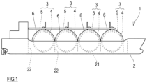
FIG. 1 is a diagram showing the schematic configuration of a ship including liquefied hydrogen tanks according to one embodiment of the present disclosure. -
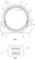
FIG. 2 is a lateral sectional view of a liquefied hydrogen carrier. -
FIG. 3 is a diagram showing the configuration of a design device for a leakage prevention tank. -
FIG. 4 is a functional block diagram of the design device for the leakage prevention tank. - Next, an embodiment of the present disclosure will be described with reference to the drawings.
-
FIG. 1 is a diagram showing the schematic configuration of aship 1 including liquefiedhydrogen tanks 3 according to one embodiment of the present disclosure. Theship 1 shown inFIG. 1 includes ahull 2 and four liquefiedhydrogen tanks 3 mounted on thehull 2. The liquefiedhydrogen tanks 3 according to the present embodiment are cargo tanks for the transportation of liquefied hydrogen, and theship 1 is a liquefied hydrogen carrier. In the present embodiment, theliquefied hydrogen tanks 3 are lined up in a ship longitudinal direction. However, when the width of the ship is large, theliquefied hydrogen tanks 3 may be lined up in a ship width direction. Moreover, the number of liquefiedhydrogen tanks 3 mounted on thehull 2 may be one or may be two or more. - In the present embodiment, these four
liquefied hydrogen tanks 3 are substantially the same in structure as each other. In the present embodiment, theliquefied hydrogen tank 3 is configured as a multilayer tank. When theliquefied hydrogen tanks 3 are mounted on theship 1, theliquefied hydrogen tanks 3 may be different in structure from each other. -
FIG. 2 is a lateral sectional view of theship 1. As shown inFIGS. 1 and2 , theliquefied hydrogen tank 3 includes: aninner shell 4 storing liquefied hydrogen; and anouter shell 5 surrounding theinner shell 4. Theinner shell 4 has a volume of more than 20,000 m3 and not more than 50,000 m3, and therefore, theliquefied hydrogen tank 3 is classified as a relatively large-scale tank. - The
inner shell 4 includes a substantially spherical inner shellmain body 41. Theinner shell 4 may include an inner shell dome projecting upward from the inner shellmain body 41. Theouter shell 5 includes a substantially spherical outer shellmain body 51. Theouter shell 5 may include an outer shell dome projecting upward from the outer shellmain body 51. Each of the inner shellmain body 41 and the outer shellmain body 51 does not necessarily have to have a spherical shape and may have a cylindrical shape that is elongated in a horizontal direction or a cylindrical shape that is elongated in a vertical direction. Or, each of the inner shellmain body 41 and the outer shellmain body 51 may have a cube shape or a cuboid shape. - The
inner shell 4 and theouter shell 5 are spaced apart from each other in a shell thickness direction. A region between theinner shell 4 and theouter shell 5 is referred to as a "first region 31." A first heat insulating layer is located in thefirst region 31. The first heat insulating layer includes a first gas filled in thefirst region 31 and thermal insulation. - The
first region 31 filled with the first gas has substantially atmospheric pressure or is in a low vacuum state. The first gas is a hydrogen gas or a helium gas. The atmospheric pressure is about 105 Pa. However, since the pressure of thefirst region 31 changes depending on temperature, the ship motion of thehull 2, and the like in some cases, "substantially atmospheric pressure" in the present specification and the claims may denote about 105 Pa and pressure higher than about 105 Pa within a range of pressure fluctuation. Moreover, the low vacuum state denotes pressure lower than the atmospheric pressure, i.e., pressure between 105 Pa and 102 Pa. When the first gas is the hydrogen gas, a gas phase portion of theinner shell 4 and thefirst region 31 may communicate with each other such that a vaporized gas generated in theinner shell 4 flows into thefirst region 31. As described above, the liquefiedhydrogen tank 3 according to the present embodiment does not include a vacuum heat insulating system. However, a vacuum heat insulating layer may be located between theinner shell 4 and theouter shell 5 in such a manner that a heat insulating layer is located in thefirst region 31, and thefirst region 31 is set to a vacuum state. - The
hull 2 includeshold spaces 21 that are open upward. Thehold spaces 21 are lined up in the ship longitudinal direction and are separated from each other bywalls 22. Then, a lower portion of theinner shell 4 and a lower portion of theouter shell 5 are accommodated in thecorresponding hold space 21. An upper portion of theouter shell 5 is covered with atank cover 6. Theouter shell 5 is surrounded by thewalls 22 and thetank cover 6 as components of thehull 2 which form thehold space 21. A region surrounded by theouter shell 5, thetank cover 6, and thewalls 22 of thehold space 21 is referred to as a "second region 32." A second heat insulating layer is located in thesecond region 32. The second heat insulating layer includes: thermal insulation located around an outer wall of theouter shell 5; and a second gas filled in thesecond region 32. - The
second region 32 filled with the second gas has substantially atmospheric pressure. The pressure of thesecond region 32 is not especially limited but may be higher than the pressure of thefirst region 31. The second gas contains at least one of: an inert gas, such as nitrogen; or dry air. For example, thesecond region 32 may be filled with the dry air, and the inert gas may be held by the second heat insulating layer. - A pair of
skirts 25 that are spaced apart from each other in the ship longitudinal direction are located in each holdspace 21. Theskirts 25 support theouter shell 5. Moreover, a pair ofsupports 35 supporting the inner shellmain body 41 are located between theinner shell 4 and theouter shell 5. In the present embodiment, theskirts 25 are located on extended lines of thesupports 35. However, the arrangement of thesupports 35 and theskirts 25 is not limited to the present embodiment. - The tank type of the liquefied
hydrogen tank 3 will be described in detail. - The
outer shell 5 is configured as an independent tank that is independent from thehull 2, and the liquefiedhydrogen tank 3 is an independent tank as a whole. The independent tank is a self-supporting tank, does not constitute part of the hull structure, and is not essential from the viewpoint of the strength of the hull. - At least one of the
inner shell 4 or theouter shell 5 is a leakage prevention tank. The leakage prevention tank has such a wall thickness that an initial defect is not propagated beyond a half of the thickness of a wall of the leakage prevention tank during a tank life of the leakage prevention tank. Since the assumed propagation of the initial defect in such leakage prevention tank is adequately small with respect to the wall thickness (tank thickness), the leakage of the liquid or gas stored in the leakage prevention tank is not assumed. The leakage prevention tank defined as above corresponds to a Type-C tank defined in the IGC Code from the viewpoint that the leakage of the stored liquid or gas is not assumed. - In the present embodiment, both of the
inner shell 4 and theouter shell 5 are the leakage prevention tanks. In the liquefiedhydrogen tank 3 according to the present embodiment, the liquefied hydrogen is stored in theinner shell 4, and the hydrogen gas is filled in thefirst region 31 between theinner shell 4 and theouter shell 5. Therefore, it is difficult to determine whether the hydrogen gas in thefirst region 31 is the hydrogen gas which has leaked from theinner shell 4 or the hydrogen gas which was filled in thefirst region 31 in advance. Since it is difficult to detect the leakage of the liquefied hydrogen from theinner shell 4 as above, theinner shell 4 is especially required to have a configuration that does not cause the leakage of the liquid hydrogen. Therefore, it is desirable that at least theinner shell 4 be the leakage prevention tank. When theinner shell 4 is the leakage prevention tank, and theouter shell 5 is not the leakage prevention tank, a required level of fracture strength with respect to theouter shell 5 lowers, and the thickness of theouter shell 5 can be reduced. This leads to a cost reduction of the amount of materials. Moreover, in the present embodiment, it is desirable that theouter shell 5 be the leakage prevention tank to prevent the combustible hydrogen gas in thefirst region 31 from leaking from theouter shell 5. Furthermore, when theouter shell 5 is the leakage prevention tank, and thefirst region 31 is filled with the first gas other than the hydrogen gas or is vacuum, theinner shell 4 does not have to be the leakage prevention tank. - A method of designing the leakage prevention tank that is the
inner shell 4 or theouter shell 5 included in the liquefiedhydrogen tank 3 will be described in detail. -
FIG. 3 is a diagram showing the schematic configuration of adesign device 8 for the leakage prevention tank. The method of designing the leakage prevention tank is executed by using thedesign device 8. Thedesign device 8 includes at least onecomputer 80. Thecomputer 80 includes aprocessor 81 and amemory 82 that stores a program executed by theprocessor 81, information, and the like. Thememory 82 is connected to theprocessor 81 such that theprocessor 81 can read information from thememory 82 and write information in thememory 82. Moreover, an input device, an output device, an auxiliary storage, a communication interface, and the like may be connected to theprocessor 81. The functionality of thedesign device 8 disclosed herein may be implemented using circuitry or processing circuitry which includes general purpose processors, special purpose processors, integrated circuits, ASICs ("Application Specific Integrated Circuits"), conventional circuitry and/or combinations thereof which are configured or programmed to perform the disclosed functionality. Processors are considered processing circuitry or circuitry as they include transistors and other circuitry therein. In the disclosure, the circuitry, units, or means are hardware that carry out the recited functionality. The hardware may be any hardware disclosed herein or otherwise known which is programmed or configured to carry out the recited functionality. When the hardware is a processor which may be considered a type of circuitry, the circuitry, means, or units are a combination of hardware and software, the software being used to configure the hardware and/or processor. -
FIG. 4 is a functional block diagram of thedesign device 8. Thedesign device 8 includes functional parts that are: astress analyzing part 84; a fatigue crackpropagation analyzing part 85 that calculates a crack propagation amount; a stress intensityfactor analyzing part 86 that calculates a stress intensity factor; a judgingpart 87; and a wallthickness determining part 88. The functional parts may be configured by thesingle computer 80 or may be distributedly configured by thecomputers 80. - To execute the method of designing the leakage prevention tank, a design wall thickness is set in the
design device 8. The design wall thickness is any value and is set within a numerical range that is executable as a wall plate of the leakage prevention tank. For example, when the wall plate of the leakage prevention tank is a steel plate, the design wall thickness may be set within a range of 60 mm or less. When the wall plate of the leakage prevention tank is a non-steel plate, the design wall thickness may be set within a range of 80 mm or less. - The method of designing the leakage prevention tank includes (1) a stress analyzing step, (2) a stress intensity factor analyzing step, (3) a crack propagation analyzing step, (4) a judging step, and (5) a wall thickness determining step. The wall thickness determining step may be performed by a designer instead of the wall
thickness determining part 88. - Since the
ship 1 sails in the waves of the sea, fluctuating pressure generated by the waves acts on a surface of thehull 2. The ship motion of thehull 2 is caused by the fluctuating pressure, and a fluctuating load by inertial force of the liquid hydrogen as the cargo acts on the leakage prevention tank by the acceleration of the ship motion. Thus, fluctuating stress, i.e., dynamic stress is generated at the leakage prevention tank by the fluctuating load. Thestress analyzing part 84 calculates the stress generated at the leakage prevention tank, especially a welded portion of the leakage prevention tank by the ship motion of thehull 2 as above. - A stress analysis method performed by the
stress analyzing part 84 is not especially limited, and examples thereof include: a numerical analysis method, such as a finite element method; and simulation. For example, thestress analyzing part 84 can calculate generated stress (generated stress distribution of the leakage prevention tank) estimated by: acquiring a fluctuating load generated due to the ship motion of thehull 2 by the waves during sailing and the waves received by thehull 2; applying this fluctuating load to a numerical analysis model of theentire ship 1 including a hull structure, a leakage prevention tank structure, and a tank support structure; and executing numerical analysis. A set wall thickness is incorporated as a parameter in the leakage prevention tank structure. The fluctuating load and the numerical analysis model may be given to thestress analyzing part 84 in advance. The fluctuating load can be calculated based on the state of the route of theship 1 by simulation or experiment. - The stress intensity
factor analyzing part 86 calculates the stress intensity factor (stress intensity factor distribution of the leakage prevention tank) of a crack. Various stress intensity factor analysis methods are known. The stress intensity factor analysis method executed by the stress intensityfactor analyzing part 86 is not especially limited, and one example thereof is a numerical analysis method, such as a finite element method. For example, the stress intensityfactor analyzing part 86 calculates the stress intensity factor of the crack by elastic stress analysis by the finite element method by using the numerical analysis model including the generated stress calculated by thestress analyzing part 84, the leakage prevention tank structure including the shape of the welded portion, the size of the initial defect of the leakage prevention tank, and the shape of the crack. The stress intensityfactor analyzing part 86 may change the analysis method in accordance with an analysis target portion of the leakage prevention tank. - The fatigue crack
propagation analyzing part 85 calculates the crack propagation amount of the initial defect of the leakage prevention tank by fatigue crack propagation analysis. The fatigue crack propagation analysis method performed by the fatigue crackpropagation analyzing part 85 is not especially limited, and examples thereof include: a numerical analysis method, such as a finite element method; and simulation. For example, the fatigue crackpropagation analyzing part 85 can calculate the crack propagation amount of the initial defect during the tank life by: acquiring the tank life of the leakage prevention tank, fracture toughness of a material of the leakage prevention tank, the stress intensity factor of the analysis target portion, and the generated stress of the analysis target portion; applying these to a fatigue crack propagation analysis model; and executing the numerical analysis. Pieces of information regarding the tank structure, such as the tank life, the size of the initial defect, the temperature of the leakage prevention tank, and the fracture toughness of the material of the leakage prevention tank, are given to the fatigue crackpropagation analyzing part 85 in advance. The size of the initial defect may be any value corresponding to the size of the initial defect which may actually exist. The tank life may be any value corresponding to the life of theship 1. The number of cycles of the generated stress during the tank life can be estimated based on the tank life. The temperature of the leakage prevention tank is the temperature of the leakage prevention tank when the liquefied hydrogen is in theinner shell 4. The fracture toughness may be the fracture toughness of the material of the leakage prevention tank when the liquefied hydrogen is in theinner shell 4. Used as the stress intensity factor of the analysis target portion may be the stress intensity factor calculated by the stress intensityfactor analyzing part 86. Used as the generated stress of the analysis target portion may be the generated stress calculated by thestress analyzing part 84. - When a requirement that the design wall thickness is "such a wall thickness that the initial defect is not propagated beyond the half of the thickness of the wall during the tank life" is satisfied, the judging
part 87 judges that the design wall thickness is "appropriate." When the requirement is not satisfied, the judgingpart 87 judges that the design wall thickness is "inappropriate." Specifically, the judgingpart 87 acquires the crack propagation amount of the initial defect during the tank life which has been calculated by the fatigue crackpropagation analyzing part 85. When the crack propagation amount does not exceed the half of the design wall thickness (i.e., when the crack propagation amount is not more than the half of the design wall thickness), the judgingpart 87 judges that the design wall thickness is appropriate. When the crack propagation amount exceeds the half of the design wall thickness, the judgingpart 87 judges that the design wall thickness is inappropriate. - The wall
thickness determining part 88 determines the wall thickness of the leakage prevention tank such that the wall thickness becomes not less than the design wall thickness which has been judged to be appropriate by the judgingpart 87. The leakage prevention tank having the wall thickness determined as above is designed. - According to the above-described method of designing the leakage prevention tank, whether or not the design wall thickness is appropriate is judged based on the crack propagation amount. In addition to this, whether or not the design wall thickness is appropriate may be judged based on the presence or absence of the generation of the instable fracture. In this case, as a judgement index of the instable fracture, the stress intensity
factor analyzing part 86 calculates the stress intensity factor of the crack (i.e., the crack in the tank life) generated in such a manner that the initial defect is propagated by the crack propagation amount calculated by the fatigue crackpropagation analyzing part 85. When this judgement index is not less than a fracture toughness value, the generation of the instable fracture during the tank life is assumed. Therefore, the judgingpart 87 acquires the judgement index and the fracture toughness value of the material of the leakage prevention tank. When the judgement index is not less than the fracture toughness value, the judgingpart 87 judges that the design wall thickness is inappropriate. When the judgement index is less than the fracture toughness value, the judgingpart 87 judges that the design wall thickness is appropriate. - The liquefied
hydrogen tank 3 according to the embodiment of the present disclosure is the liquefiedhydrogen tank 3 mounted on theship 1 and includes: theinner shell 4 storing the liquefied hydrogen; and theouter shell 5 surrounding theinner shell 4. At least one of theinner shell 4 or theouter shell 5 is the leakage prevention tank. The leakage prevention tank has such a wall thickness that an initial defect is not propagated beyond a half of a thickness of a wall of the leakage prevention tank during a tank life of the leakage prevention tank. - In the liquefied
hydrogen tank 3, both of theinner shell 4 and theouter shell 5 may be the leakage prevention tanks. - In the liquefied
hydrogen tank 3, the hydrogen gas may be filled in a region between theinner shell 4 and theouter shell 5, and theinner shell 4 may be the leakage prevention tank. - In the liquefied
hydrogen tank 3, the hydrogen gas may be filled in a region between theinner shell 4 and theouter shell 5, and theouter shell 5 may be the leakage prevention tank. - According to the liquefied
hydrogen tank 3 configured as above, even when the leakage prevention tank included in the liquefiedhydrogen tank 3 has the initial defect, the propagation of the initial defect during the tank life is adequately small with respect to the wall thickness, and therefore, the leakage of the liquid or gas stored in the leakage prevention tank is not assumed. Such leakage prevention tank corresponds to the Type-C tank defined in the IGC Code from the viewpoint that the leakage of the stored liquid or gas is not assumed. Therefore, a secondary protective wall can be omitted from the leakage prevention tank and the liquefiedhydrogen tank 3 including the leakage prevention tank. - In the liquefied
hydrogen tank 3, theinner shell 4 may have a volume of more than 20,000 m3 and not more than 50,000 m3. - Even when the liquefied
hydrogen tank 3 is a relatively large-scale tank as described above, the liquefiedhydrogen tank 3 may have a wall thickness that can be actually built, while having a predetermined leakage preventing function. - Moreover, the method of designing the liquefied
hydrogen tank 3 according to the present embodiment includes: acquiring, by a first processor (fatigue crack propagation analyzing part 85), the tank life of the leakage prevention tank, the size of the initial defect of the leakage prevention tank, the temperature of the leakage prevention tank, the stress intensity factor of the leakage prevention tank, and the stress generated at the leakage prevention tank; calculating, by the first processor by the fatigue crack propagation analysis, the crack propagation amount of the initial defect which is propagated by the stress having the number of cycles corresponding to the tank life; acquiring, by a second processor (judging part 87), the calculated crack propagation amount and the design wall thickness of the leakage prevention tank; when the crack propagation amount does not exceed the half of the design wall thickness, judging by the second processor that the design wall thickness is appropriate; when the crack propagation amount exceeds the half of the design wall thickness, judging by the second processor that the design wall thickness is inappropriate; and determining the wall thickness of the leakage prevention tank such that the wall thickness becomes not less than the design wall thickness which has been judged to be appropriate. The first processor and the second processor may be physically the same processor or may be processors independent from each other. - According to the above method of designing the liquefied
hydrogen tank 3, the tank which does not cause the leakage of the stored gas or liquid while having the wall thickness within a realistic range can be designed. - The above method of designing the liquefied
hydrogen tank 3 may further include: calculating, by a third processor (stress intensity factor analyzing part 86), as the judgement index the stress intensity factor of the crack generated in such a manner that the initial defect is propagated during the tank life; acquiring, by a fourth processor (wall thickness determining part 88), the fracture toughness value of the material of the leakage prevention tank; and when the judgement index is not less than the fracture toughness value, judging by the fourth processor that the design wall thickness is inappropriate, since the generation of the instable fracture during the tank life is assumed. The stress intensity factor may be calculated with respect to the shape of the final crack after the tank life or may be repeatedly calculated with respect to the shape of the crack which is being propagated during the tank life. Moreover, the first to fourth processors may be physically the same processor or may be processors independent from each other. - According to the above method, whether or not the design wall thickness is appropriate is further judged based on the presence or absence of the generation of the instable fracture. Therefore, the tank which can more surely prevent the leakage can be designed.
- In the above embodiment, the
inner shell 4 is typically classified as a large-scale tank. However, theinner shell 4 may be a tank classified as a small-scale tank having a volume of not more than 20,000 m3 and may be the leakage prevention tank. To be specific, the structure of the liquefiedhydrogen tank 3 according to the present disclosure and the method of designing the liquefiedhydrogen tank 3 according to the present disclosure may be applied to small-scale tanks and large-scale tanks of more than 50,000 m3 regardless of the scale of the tank. - In the above embodiment, the liquefied
hydrogen tank 3 is the cargo tank. However, the structure of the liquefiedhydrogen tank 3 according to the present disclosure and the method of designing the liquefiedhydrogen tank 3 according to the present disclosure may be applied to a fuel tank mounted on theship 1. In this case, theship 1 is not limited to the liquefied hydrogen carrier. - The foregoing discussion of the present disclosure has been presented for purposes of illustration and description. The foregoing is not intended to limit the present disclosure to the form or forms disclosed herein. In the foregoing Detailed Description for example, various features of the present disclosure are grouped together in one embodiment for the purpose of streamlining the disclosure. The features of the present disclosure may be combined in alternate embodiments, configurations, or aspects other than those discussed above.
Claims (6)
- A liquefied hydrogen tank mounted on a ship,
the liquefied hydrogen tank comprising:an inner shell storing liquefied hydrogen; andan outer shell surrounding the inner shell, wherein:at least one of the inner shell or the outer shell is a leakage prevention tank; andthe leakage prevention tank has such a wall thickness that an initial defect is not propagated beyond a half of a thickness of a wall of the leakage prevention tank during a tank life of the leakage prevention tank. - The liquefied hydrogen tank according to claim 1, wherein both of the inner shell and the outer shell are the leakage prevention tanks.
- The liquefied hydrogen tank according to claim 1, wherein:a hydrogen gas is filled in a region between the inner shell and the outer shell;the inner shell is the leakage prevention tank; andthe outer shell is not the leakage prevention tank.
- The liquefied hydrogen tank according to any one of claims 1 to 3, wherein the inner shell has a volume of more than 20,000 m3 and not more than 50,000 m3.
- A method of designing a liquefied hydrogen tank which is mounted on a ship and includes an inner shell storing liquefied hydrogen and an outer shell surrounding the inner shell, at least one of the inner shell or the outer shell being a leakage prevention tank,
the method comprising:acquiring, by a first processor, a tank life of the leakage prevention tank, a size of an initial defect of the leakage prevention tank, a temperature of the leakage prevention tank, a stress intensity factor of the leakage prevention tank, and stress generated at the leakage prevention tank;calculating, by the first processor by fatigue crack propagation analysis, a crack propagation amount of the initial defect which is propagated by the stress having the number of cycles corresponding to the tank life;acquiring, by a second processor, the calculated crack propagation amount and a design wall thickness of the leakage prevention tank;when the crack propagation amount does not exceed a half of the design wall thickness, judging by the second processor that the design wall thickness is appropriate;when the crack propagation amount exceeds the half of the design wall thickness, judging by the second processor that the design wall thickness is inappropriate; anddetermining a wall thickness of the leakage prevention tank such that the wall thickness becomes not less than the design wall thickness which has been judged to be appropriate. - The method according to claim 5, further comprising:calculating, by a third processor, as a judgement index the stress intensity factor of a crack generated in such a manner that the initial defect is propagated during the tank life;acquiring, by a fourth processor, a fracture toughness value of a material of the leakage prevention tank; andwhen the judgement index is not less than the fracture toughness value, judging by the fourth processor that the design wall thickness is inappropriate, since the generation of an instable fracture during the tank life is assumed.
Applications Claiming Priority (2)
| Application Number | Priority Date | Filing Date | Title |
|---|---|---|---|
| JP2021144154A JP7739094B2 (en) | 2021-09-03 | 2021-09-03 | Design method for liquefied hydrogen tanks |
| PCT/JP2022/030428 WO2023032615A1 (en) | 2021-09-03 | 2022-08-09 | Liquefied hydrogen tank and method for designing same |
Publications (2)
| Publication Number | Publication Date |
|---|---|
| EP4397600A1 true EP4397600A1 (en) | 2024-07-10 |
| EP4397600A4 EP4397600A4 (en) | 2025-08-20 |
Family
ID=85412238
Family Applications (1)
| Application Number | Title | Priority Date | Filing Date |
|---|---|---|---|
| EP22864201.3A Pending EP4397600A4 (en) | 2021-09-03 | 2022-08-09 | LIQUID HYDROGEN TANK AND METHOD FOR DESIGNING SAME |
Country Status (5)
| Country | Link |
|---|---|
| EP (1) | EP4397600A4 (en) |
| JP (1) | JP7739094B2 (en) |
| KR (1) | KR20240047398A (en) |
| CN (1) | CN117836221B (en) |
| WO (1) | WO2023032615A1 (en) |
Families Citing this family (3)
| Publication number | Priority date | Publication date | Assignee | Title |
|---|---|---|---|---|
| WO2025196931A1 (en) * | 2024-03-19 | 2025-09-25 | 川崎重工業株式会社 | Tank supporting structure for hull and liquefied gas carrier |
| CN119284087A (en) * | 2024-09-27 | 2025-01-10 | 江南造船(集团)有限责任公司 | A method for evaluating the longitudinal strength of a half-ship floating |
| CN121822727B (en) * | 2026-03-09 | 2026-05-19 | 海大清能船舶(大连)有限公司 | A hydrogen-powered inland waterway container ship |
Family Cites Families (11)
| Publication number | Priority date | Publication date | Assignee | Title |
|---|---|---|---|---|
| TW359736B (en) * | 1997-06-20 | 1999-06-01 | Exxon Production Research Co | Systems for vehicular, land-based distribution of liquefied natural gas |
| JP4975692B2 (en) | 2008-07-16 | 2012-07-11 | 新日本製鐵株式会社 | Fuel tank |
| JP5785118B2 (en) | 2012-03-06 | 2015-09-24 | 三井造船株式会社 | Ship, offshore floating facility, and liquefied natural gas storage method |
| EP2990715B1 (en) | 2013-04-23 | 2021-07-14 | Kawasaki Jukogyo Kabushiki Kaisha | Double-shell ship tank structure and liquefied gas carrier |
| JP5863900B2 (en) * | 2014-07-24 | 2016-02-17 | 三井造船株式会社 | Liquefied gas transport ship and design method of liquefied gas transport ship |
| CN205221610U (en) * | 2015-12-03 | 2016-05-11 | 新疆联诚重工科技有限公司 | Prevent leaking double -layer oil tank |
| GB201702362D0 (en) * | 2017-02-14 | 2017-03-29 | Univ Ulster | Composite pressure vessel for hydrogen storage |
| CN107618779A (en) * | 2017-10-17 | 2018-01-23 | 四川鑫福石油化工设备制造有限责任公司 | A kind of new anti-leakage double-layer oil tank |
| KR20190054846A (en) * | 2017-11-14 | 2019-05-22 | 유병용 | Double wall pressure vessel |
| CN113661134B (en) * | 2019-04-05 | 2023-03-10 | 川崎重工业株式会社 | Liquefied gas tank and liquefied gas carrying ship |
| JP7527107B2 (en) * | 2019-12-27 | 2024-08-02 | 三菱造船株式会社 | Cargo tank unit and ship |
-
2021
- 2021-09-03 JP JP2021144154A patent/JP7739094B2/en active Active
-
2022
- 2022-08-09 WO PCT/JP2022/030428 patent/WO2023032615A1/en not_active Ceased
- 2022-08-09 KR KR1020247007791A patent/KR20240047398A/en active Pending
- 2022-08-09 EP EP22864201.3A patent/EP4397600A4/en active Pending
- 2022-08-09 CN CN202280054131.0A patent/CN117836221B/en active Active
Also Published As
| Publication number | Publication date |
|---|---|
| WO2023032615A1 (en) | 2023-03-09 |
| KR20240047398A (en) | 2024-04-12 |
| CN117836221B (en) | 2026-07-31 |
| JP7739094B2 (en) | 2025-09-16 |
| CN117836221A (en) | 2024-04-05 |
| EP4397600A4 (en) | 2025-08-20 |
| JP2023037410A (en) | 2023-03-15 |
Similar Documents
| Publication | Publication Date | Title |
|---|---|---|
| JP7739094B2 (en) | Design method for liquefied hydrogen tanks | |
| Kim et al. | Design of Independent Type‐B LNG Fuel Tank: Comparative Study between Finite Element Analysis and International Guidance | |
| CN104443283B (en) | Local screen-wall system and ship or marine structure applied to Type B independent tank | |
| Gavory et al. | Sloshing in membrane LNG carriers and its consequences from a designer’s perspective | |
| Jeong et al. | Calculation of boil-off gas (BOG) generation of KC-1 membrane LNG tank with high density rigid polyurethane foam by numerical analysis | |
| KR102749075B1 (en) | Fuel tanks, and vessels | |
| Kim et al. | Development of strength evaluation methodology for independent IMO type C tank with LH2 carriers | |
| KR20170022667A (en) | Leakage Liquefied Gas of Storage Tank Treatment System and Method | |
| Schiaroli et al. | Consequence analysis of a bunkering facility for liquid hydrogen loading and unloading | |
| JP2021160400A (en) | Liquefied gas storage ship | |
| Lee et al. | New methodology for estimating the minimum design vapor pressure of prismatic pressure vessel for on-ship application | |
| KR100961863B1 (en) | Ship's lanyard storage tank structure with reduced sloshing | |
| KR100762368B1 (en) | Initial design method of ship | |
| Choi et al. | Estimation of the design pressure of a prismatic LNG storage vessel | |
| KR20220098236A (en) | Cargo Tank Units and Vessels | |
| Tamura et al. | New LPG carrier adopting highly reliable cargo tank–IMO tank type B | |
| KR102795513B1 (en) | Apparatus for designing liquefied gas tank and operating method thereof | |
| Heo et al. | Structural assessment techniques for a newly developed LNG cargo containment system | |
| KR20240058370A (en) | Bunkering Vessel capable of charging multiple fuels | |
| KR20200048261A (en) | Liquefied gas storage tank and ship with it | |
| JP6282014B2 (en) | Free-standing square tank and ship | |
| KR102929671B1 (en) | Method for manufacturing liquefied gas tank, liquefied gas tank and ship having liquefied gas tank | |
| KR20220138540A (en) | Liquefied Gas Storage Tank and Ship having the same | |
| Kalina et al. | STRENGTH CHARACTERISTICS OF LNG TANKS AND THEIR APPLICATION IN INLAND NAVIGATION. | |
| Tuswan et al. | Design optimization of Bakelite support for LNG ISO tank 40 ft using finite element analysis |
Legal Events
| Date | Code | Title | Description |
|---|---|---|---|
| STAA | Information on the status of an ep patent application or granted ep patent |
Free format text: STATUS: THE INTERNATIONAL PUBLICATION HAS BEEN MADE |
|
| PUAI | Public reference made under article 153(3) epc to a published international application that has entered the european phase |
Free format text: ORIGINAL CODE: 0009012 |
|
| STAA | Information on the status of an ep patent application or granted ep patent |
Free format text: STATUS: REQUEST FOR EXAMINATION WAS MADE |
|
| 17P | Request for examination filed |
Effective date: 20240403 |
|
| AK | Designated contracting states |
Kind code of ref document: A1 Designated state(s): AL AT BE BG CH CY CZ DE DK EE ES FI FR GB GR HR HU IE IS IT LI LT LU LV MC MK MT NL NO PL PT RO RS SE SI SK SM TR |
|
| DAV | Request for validation of the european patent (deleted) | ||
| DAX | Request for extension of the european patent (deleted) | ||
| REG | Reference to a national code |
Ref country code: DE Ref legal event code: R079 Free format text: PREVIOUS MAIN CLASS: B65D0090220000 Ipc: F17C0003020000 |
|
| A4 | Supplementary search report drawn up and despatched |
Effective date: 20250723 |
|
| RIC1 | Information provided on ipc code assigned before grant |
Ipc: F17C 3/02 20060101AFI20250717BHEP Ipc: B65D 90/22 20060101ALI20250717BHEP Ipc: B63B 25/16 20060101ALI20250717BHEP Ipc: B63B 71/00 20200101ALI20250717BHEP Ipc: G06F 30/23 20200101ALI20250717BHEP Ipc: G06F 30/15 20200101ALI20250717BHEP Ipc: G06F 30/18 20200101ALI20250717BHEP Ipc: G06F 30/20 20200101ALI20250717BHEP |
|
| GRAP | Despatch of communication of intention to grant a patent |
Free format text: ORIGINAL CODE: EPIDOSNIGR1 |
|
| STAA | Information on the status of an ep patent application or granted ep patent |
Free format text: STATUS: GRANT OF PATENT IS INTENDED |
|
| RIC1 | Information provided on ipc code assigned before grant |
Ipc: F17C 3/02 20060101AFI20260618BHEP Ipc: B65D 90/22 20060101ALI20260618BHEP Ipc: B63B 25/16 20060101ALI20260618BHEP Ipc: B63B 71/00 20200101ALI20260618BHEP Ipc: G06F 30/23 20200101ALI20260618BHEP Ipc: G06F 30/15 20200101ALI20260618BHEP Ipc: G06F 30/18 20200101ALI20260618BHEP Ipc: G06F 30/20 20200101ALI20260618BHEP |
|
| INTG | Intention to grant announced |
Effective date: 20260703 |
|
| RIN1 | Information on inventor provided before grant (corrected) |
Inventor name: SHIMODA, TAICHIRO Inventor name: TOMINAGA, HARUHIKO Inventor name: MOCHIDA, KUNIHIKO Inventor name: KANO, DAICHI Inventor name: INOHARA, MASAYOSHI |