EP4397538A1 - A bunk for a vehicle cab - Google Patents
A bunk for a vehicle cab Download PDFInfo
- Publication number
- EP4397538A1 EP4397538A1 EP23150598.3A EP23150598A EP4397538A1 EP 4397538 A1 EP4397538 A1 EP 4397538A1 EP 23150598 A EP23150598 A EP 23150598A EP 4397538 A1 EP4397538 A1 EP 4397538A1
- Authority
- EP
- European Patent Office
- Prior art keywords
- bunk
- cab
- frame
- beams
- segments
- Prior art date
- Legal status (The legal status is an assumption and is not a legal conclusion. Google has not performed a legal analysis and makes no representation as to the accuracy of the status listed.)
- Granted
Links
Images





Classifications
-
- B—PERFORMING OPERATIONS; TRANSPORTING
- B62—LAND VEHICLES FOR TRAVELLING OTHERWISE THAN ON RAILS
- B62D—MOTOR VEHICLES; TRAILERS
- B62D33/00—Superstructures for load-carrying vehicles
- B62D33/06—Drivers' cabs
- B62D33/0612—Cabins with living accommodation, especially for long distance road vehicles, i.e. sleeping, cooking, or other facilities
-
- B—PERFORMING OPERATIONS; TRANSPORTING
- B60—VEHICLES IN GENERAL
- B60N—SEATS SPECIALLY ADAPTED FOR VEHICLES; VEHICLE PASSENGER ACCOMMODATION NOT OTHERWISE PROVIDED FOR
- B60N3/00—Arrangements or adaptations of other passenger fittings, not otherwise provided for
- B60N3/008—Arrangements or adaptations of other passenger fittings, not otherwise provided for of beds
-
- A—HUMAN NECESSITIES
- A47—FURNITURE; DOMESTIC ARTICLES OR APPLIANCES; COFFEE MILLS; SPICE MILLS; SUCTION CLEANERS IN GENERAL
- A47C—CHAIRS; SOFAS; BEDS
- A47C17/00—Sofas; Couches; Beds
- A47C17/64—Travelling or camp beds
- A47C17/80—Travelling or camp beds adapted to be used in or connected to vehicles
-
- B—PERFORMING OPERATIONS; TRANSPORTING
- B60—VEHICLES IN GENERAL
- B60N—SEATS SPECIALLY ADAPTED FOR VEHICLES; VEHICLE PASSENGER ACCOMMODATION NOT OTHERWISE PROVIDED FOR
- B60N2/00—Seats specially adapted for vehicles; Arrangement or mounting of seats in vehicles
- B60N2/24—Seats specially adapted for vehicles; Arrangement or mounting of seats in vehicles for particular purposes or particular vehicles
- B60N2/42—Seats specially adapted for vehicles; Arrangement or mounting of seats in vehicles for particular purposes or particular vehicles the seat constructed to protect the occupant from the effect of abnormal g-forces, e.g. crash or safety seats
- B60N2/4207—Seats specially adapted for vehicles; Arrangement or mounting of seats in vehicles for particular purposes or particular vehicles the seat constructed to protect the occupant from the effect of abnormal g-forces, e.g. crash or safety seats characterised by the direction of the g-forces
- B60N2/4214—Seats specially adapted for vehicles; Arrangement or mounting of seats in vehicles for particular purposes or particular vehicles the seat constructed to protect the occupant from the effect of abnormal g-forces, e.g. crash or safety seats characterised by the direction of the g-forces longitudinal
Definitions
- Industrial vehicles can be used to carry freight between places located far from each other. As a consequence, the driver of such a vehicle can spend several days on the road and may sleep in the vehicle cab. For this reason, cabs are generally equipped with bunks located behind the driver and passenger seats.
- the cab In case of a vehicular collision, the cab can be deformed and the bunk can be pushed forward with a risk of hitting and injuring the cab occupant(s).
- the bunk changes from its normal state to its collapsed state, the bunk being deformed by compression.
- the side beams can be substantially straight.
- the side beams are not broken, but only deformed, meaning that their overall shape has changed
- the side beams are still secured to the front and the rear beams.
- the front and rear segments could ultimately be disconnected from each other and/or from the corresponding front and rear beam, and some components of the bunk could be broken.
- the frame can be constituted by said front, rear and side beams. It may substantially form a rectangle.
- the supporting structure not necessarily covers the whole inner surface defined by the frame and/or is not necessarily continuous over said surface. It may take different forms provided it can support a mattress.
- the bunk may further comprise fasteners for maintaining the front and rear segments of the side beams in the normal state, said fasteners being breakable above a predetermined threshold, to allow the bunk to change to its collapsed state.
- the fasteners may join the front and rear segments.
- the supporting structure comprises slats that extend between the front and the rear beams, for example substantially longitudinally.
- the front end, respectively the rear end, of each slat may be coupled to the front beam, respectively the rear beam, by a coupler which is breakable above a predetermined threshold.
- Each slat may include a bar and a cap mounted on each bar end, the couplers being arranged on the caps.
- the slat end faces may be angled relative to the slat axis, said end faces preferably being substantially parallel. Such an implementation allows guiding the movement of the slats when the bunk changes from its normal position to its collapsed position, and making said movement smoother. Therefore, the compression of the bunk is easier.
- the angled end faces of the slats may be provided on said caps.
- the slats may be angled relative to the rear beam by an angle that is comprised between 74° and 89°.
- the slats are not perpendicular to the front and rear beams, i.e. do not extend exactly longitudinally: they are tilted with respect to the longitudinal direction by an angle comprised between 2° and 10°.
- Such an arrangement makes the beginning of the pivoting movement of the slats easier, and furthermore ensures that the movement is directed appropriately.
- the corresponding angle orientation is adapted to the orientation of the slats.
- At least one beam may comprise a flange extending above an edge of the supporting structure and configured to prevent said supporting structure from moving apart from said beam.
- the flange may extend above one slat end portion.
- the flange preferably extends over all length of said beam.
- said beam has a C-shaped cross-section.
- the bunk may comprise a base having:
- Figure 1 shows a vehicle 100, such as a truck, and more particularly a cab 101 of the vehicle 100.
- the cab 101 has a front wall 102, two side walls 103 and a rear wall 104.
- the side walls 103 each include a pillar 105, conventionally referred to as "B pillar".
- the side walls 103 further have a door 106 located between the B pillar 105 and the front wall 102.
- the cab 101 further has a floor 107, and forms a driver compartment 108.
- the cab 101 also comprises two seats 109, one for the driver and one for a possible passenger.
- the bunk 1 also comprises a supporting structure 50 which is coupled to the frame 10 and extends over the inner surface 5.
- the supporting structure 50 aims at supporting a mattress and a bunk occupant.
- the bunk 1 can be in a use position, as illustrated in figures 1 and 15 , in which the frame 10 is substantially horizontal, or in a storage position (not shown) which allows easier or even unencumbered access to the area behind the seats 109. Said area may include storage compartments. For example, in the storage position, the bunk 1 may be located against the cab rear wall 104.
- the bunk 1 is described when it is in its use position, and in the normal state, i.e. its state at the first use, while it has not been deformed nor damaged.
- the front beam 2 and the rear beam 3 are spaced apart by a nominal distance Dn, along the longitudinal direction X, as shown in figure 19 .
- a first example of the bunk 1 is described with reference to figures 2 to 20 .
- the front beam 2 and the rear beam 3 may comprise a profile 21, respectively 31, having a square cross-section.
- a holder 23, 33 for the supporting structure 50 may be secured on the inner face 22, 32 of each of the front beam 2 and the rear beam 3, i.e. the face turned towards the inner surface 5, thus towards the other beam.
- the holder 23, 33 may comprise a lower wall 24, 34 extending substantially in a horizontal plane, and on which the supporting structure 50 can rest.
- the lower wall 24, 34 may be provided with attachments for the supporting structure 50.
- said attachments are holes which are preferably arranged at regular intervals over the whole length of the front and rear beams 2, 3.
- the lower wall 34 of the rear beam 3 may comprise circular holes 35 having a closed contour while the lower wall 24 of the front beam 2 may comprise elongated holes 25 which open at the inner edge of the lower wall 24.
- the holder 23 of the front beam 2 can have the shape of a C which is open towards the rear beam 3, said holder thus having an upper flange 26 which is substantially horizontal.
- the base portion 27 of the holder 23, which joins the lower wall 24 and the upper flange 26 may be welded to the profile 21.
- the holder 33 of the rear beam 3 can be L-shaped, the lower wall 34 forming one wing of the holder 33 and the other wing 37 being welded to the profile 31.
- each segment 41, 42 have a length that is smaller than the nominal distance Dn and, furthermore, the sum of the lengths of the segments 41, 42 is higher than the nominal distance Dn.
- the front segment 41 and the rear segment 42 substantially have the same length that is higher than half the nominal distance Dn.
- angle ⁇ is defined between the slat angle A51 and the axis of the rear beam 3, which in this example is the transverse direction Y.
- the slats 51 can be not exactly horizontal but slightly bent upwards, as shown in figure 11 .
- each slat 51 comprises a bar 54 that may have a rectangular cross-section, and a cap 60 mounted on each bar end.
- the cap 60 can be made of plastic.
- the cap 60 forms a cavity into which one end of the slat 51 is housed.
- the cap 60 has a lower face 61 that rests on the lower wall 24, 34 of the holder 23, 33 of the corresponding beam 2, 3. From the lower face 61 extends a coupler 65 for coupling the slat 51 to the front beam 2, respectively the rear beam 3.
- the couplers 65 are configured to engage the holes 25, 35 provided on the holders 23, 33 of the beams 2, 3.
- Each coupler 65 can protrude vertically downward from the cap lower face 61 and can have an annular groove 66 allowing the coupler 65 to be fixed in the corresponding hole 25, 35 by clipping, as the lower wall 24, 34 is sandwiched between the cap lower face 61 and the lower wall 24, 34 while being partly received in the annular groove 66.
- the cap 60 at the front end 52 of each slat 51 is engaged in the holder 23 of the front beam 2, between the lower wall 24 and the upper flange 26.
- the flange 26 extends above the front end 52 of the slat 51.
- the cap 60 has an end face 62 which is preferably angled relative to the slat axis A51 by an angle ⁇ , in the mounted position of the cap 60 on the bar 54.
- Angle ⁇ may be comprised between 60° and 75°, as shown in figure 8 .
- the end faces 62 of one slat 51 are preferably substantially parallel.
- the bunk 1 may comprise hooks 38 secured to the rear beam 3, for example welded to it, and coupled to an organ such as a rod secured to the cab rear wall 104.
- Said hooks 38 thus form attachments of the frame 10 to the cab 101, especially of the rear part of the frame 10.
- Said hooks 38 further form an hinge that allows moving the bunk 1 from its use position to its storage position, by a pivoting movement about a transverse axis located above the plane in which the bunk 1 lies in its use position.
- the bunk 1 may further comprise a base 70, as shown in figure 15 .
- the base 70 can be made of reinforcement bars.
- the base 70 has a support 71 on which the frame 10 can rest in a use position of the bunk 1.
- the support 71 has mounts 72 for being secured to the cab 101. More specifically, the support 71 may include or be constituted by a transverse bar on which the front beam 2 of the frame 10 can rest, as shown in figure 18 . Although in figure 18 the frame 10 is depicted as being directly in contact with the support 71, it could be envisaged that the frame 10 rests on an intermediate panel which itself rests on the support 71.
- the ends of the transverse bar 71 are secured by any appropriate means, such as fasteners, to the cab side walls 103, preferably to the B pillar 105.
- the base 70 also has poles 73 extending substantially vertically and downward from the support 71. Each pole 73 is provided at its lower end with a mount 74 secured to the cab floor 107.
- the bunk 1 is maintained in the use position by at least one stop arranged on the frame 10 and configured to cooperate with a component secured to the cab 101.
- one stop may be provided on at least a side front part of the frame 10.
- one stop 80 protrudes from each side beam 4, close to the front beam 2, substantially transversely and away from the frame 10.
- the stop 80 may be in the form of a L-bracket having a first wing 81 which is secured to the side beam 4, for example by welding, and extends towards the adjacent side wall 103 of the cab 101, and a second wing 82 which extends downward, for example in a plane (X,Z).
- the second wing 82 may comprise an opening 83 and a hooked end 84.
- the stop 80 cooperates with a locker 85 secured to the cab side wall 103, preferably to the B pillar 105, by means of an appropriate member such as a bracket (not shown). More specifically, a tab 86 of the locker 85 is inserted in the opening 83 of the stop second wing 82.
- the stop 80 and locker 85 prevent the frame 10 from moving to the storage position, in particular in case of a roll-over of the vehicle 100.
- the bunk 1 is configured to change from its normal state to a collapsed state, especially in case of a vehicular collision, as will now be described.
- the stop 90 may be secured to the front beam 2 as shown in figures 5 and 14 .
- the stop 90 may be in the form of a L-bracket having a first wing 91 which is secured to and under the front beam 2, for example by welding, and extends substantially horizontally, and a second wing 92 which extends downward, preferably in a plane (Y,Z).
- the second wing 92 may comprise an end 94 bent forward.
- the stop 90 is configured to engage the support 71 of the base from the rear, thereby preventing a further forward movement of the frame 10 with respect to the cab 101.
- Angles ⁇ and ⁇ , and the corresponding orientations conferred to the slats 51 and end faces 62, are consistent with each other. This means that the orientation due to angle ⁇ and the orientation due to angle ⁇ both tend to move the slat 51 relative to the rear beam 3 according to the same pivoting direction.
- the movement of the slats 51 correspond to the front end 52 of the slat 51 moving towards the right of the figure.
- Figure 20 shows the bunk 1 in the collapsed state.
- the front and rear beams 2, 3 are spaced apart by a distance D that is smaller than the nominal distance Dn; the side beams 4 are retracted, with the front segment 41 engaged further into the rear segment 42; the slats 51 are angled relative to the rear beam 3 by an angle which may be greater than 40°.
- the bunk 1 has not been projected inside the driver compartment 108 and has not hit the seats 109. Depending on the impact, the bunk 1 may have come into contact with the seats 109, but with a very limited speed unlikely to cause injuries.
- the frame 10 has kept its overall shape but has been compressed along the longitudinal direction X.
- a second example of the bunk 1 is described with reference to figures 21 to 23 .
- the bunk is substantially identical to the one of the first example except for the side beams 4 which are not telescopic.
Landscapes
- Engineering & Computer Science (AREA)
- Transportation (AREA)
- Mechanical Engineering (AREA)
- Health & Medical Sciences (AREA)
- General Health & Medical Sciences (AREA)
- Nursing (AREA)
- Aviation & Aerospace Engineering (AREA)
- Chemical & Material Sciences (AREA)
- Combustion & Propulsion (AREA)
- Body Structure For Vehicles (AREA)
Abstract
- a frame (10) attached to the cab, having a front beam (2) a rear beam (3) and side beams (4), each side beam comprising a front segment (41) and a rear segment (42),
- a supporting structure (50) coupled to the frame and extending over the inner surface (5) of the frame.
- from a normal state, in which the front and rear beams are spaced apart by a nominal distance Dn, the front and rear segments being in a first relative position,
- to a collapsed state in which the front and rear beams are spaced apart by a distance D < Dn, and in which the front and rear segments are in a second relative position
Description
- The disclosure relates to a bunk for a vehicle cab. The disclosure can be applied in heavy-duty vehicles, such as trucks, buses, and construction equipment. Although the disclosure may be described with respect to a particular vehicle, the disclosure is not restricted to any particular vehicle.
- Industrial vehicles can be used to carry freight between places located far from each other. As a consequence, the driver of such a vehicle can spend several days on the road and may sleep in the vehicle cab. For this reason, cabs are generally equipped with bunks located behind the driver and passenger seats.
- In case of a vehicular collision, the cab can be deformed and the bunk can be pushed forward with a risk of hitting and injuring the cab occupant(s).
- According to a first aspect, the disclosure concerns a bunk for a cab of a vehicle, comprising:
- a frame having a front beam and a rear beam which globally extend along a transverse direction, and side beams which globally extend along a longitudinal direction, said front, rear and side beams being secured to one another, the frame defining an inner surface and further comprising attachments for attaching the frame to the cab,
- a supporting structure coupled to the frame and extending over the inner surface,
- wherein, in a normal state, the side beams maintain a nominal distance between the front and the rear beams,
- each side beam comprising at least a front segment connected to the front beam and a rear segment connected to the rear beam, wherein the segments globally extend along the longitudinal direction, are linked to each another and have a length smaller than the nominal distance, the front and rear segments being in a first relative position in the normal state,
- the bunk being configured to change from its normal state to a collapsed state in which the front and rear beams are spaced apart by a distance that is smaller than the nominal distance, and in which the front and rear segments remain linked to each another while being in a second relative position different from the first relative position.
- Thus, following a vehicular collision, the bunk changes from its normal state to its collapsed state, the bunk being deformed by compression. In addition to dissipating energy, this limits or even avoids the risk of the bunk being moved or thrown forward up to the seats or even up to the occupants, as compared to bunks having rigid structures.
- In the normal state, the side beams can be substantially straight. In the collapsed state, preferably, the side beams are not broken, but only deformed, meaning that their overall shape has changed Also, preferably, the side beams are still secured to the front and the rear beams. However, in case of a powerful collision, the front and rear segments could ultimately be disconnected from each other and/or from the corresponding front and rear beam, and some components of the bunk could be broken.
- The terms "transverse" and "longitudinal" are used with respect to the vehicle, in the mounted position of the bunk in the vehicle. By "globally" is meant that the concerned beam is not necessarily straight over its whole length, but may include segments that extend in another direction.
- The frame can be constituted by said front, rear and side beams. It may substantially form a rectangle. The supporting structure not necessarily covers the whole inner surface defined by the frame and/or is not necessarily continuous over said surface. It may take different forms provided it can support a mattress.
- In an example, the front and rear segments are slidably linked to each other along a sliding direction that is substantially longitudinal. In other words, the front and rear segments may slide along their axes. Such an example forms a telescopic structure. For example, one segment can slide inside the other. The front segment preferably has its front end fixedly secured to the front beam, without possible relative movement, and the rear segment preferably has its rear end fixedly secured to the rear beam, without possible relative movement.
- In another example, the front segment, respectively the rear segment, is pivotally connected to the front beam, respectively the rear beam, about a pivoting axis that is substantially vertical, the front and rear segments further being pivotally connected to each other about at least one pivoting axis that is substantially vertical, whereby in the collapsed state the front and rear segments are angled relative to each other. In other words, in the collapsed state, the segments no longer extend longitudinally; they are no longer perpendicular to the front and rear beams. Preferably, the segments are angled towards the inner surface, i.e. towards the vehicle median longitudinal plane, as an outward movement may not be possible because of the cab walls).
- The bunk may further comprise fasteners for maintaining the front and rear segments of the side beams in the normal state, said fasteners being breakable above a predetermined threshold, to allow the bunk to change to its collapsed state. The fasteners may join the front and rear segments.
- Preferably, the supporting structure is configured to be deformed, in order not to hinder the longitudinal compression of the bunk. The supporting structure can be deformed as a whole, meaning that the components of said supporting structure may keep their shape but move with respect to the frame. The supporting structure preferably is not broken in the collapsed state, but could break in case of a powerful collision.
- In an example, the supporting structure comprises slats that extend between the front and the rear beams, for example substantially longitudinally. The front end, respectively the rear end, of each slat may be coupled to the front beam, respectively the rear beam, by a coupler which is breakable above a predetermined threshold.
- After the couplers are broken, the slats are free to move with respect to the front and rear beams, for example by pivoting with respect to the front and rear beams about a vertical axis, while preferably remaining in the plane of the inner surface defined by the frame. Such a tilting movement makes it possible not to hinder the change of the bunk to its collapsed state; moreover, this avoids breaking the bunk main components (frame, slats). Even if such components cannot be reused, it prevents broken parts to be projected inside the cab and to injure the occupants.
- Each slat may include a bar and a cap mounted on each bar end, the couplers being arranged on the caps.
- The slat end faces may be angled relative to the slat axis, said end faces preferably being substantially parallel. Such an implementation allows guiding the movement of the slats when the bunk changes from its normal position to its collapsed position, and making said movement smoother. Therefore, the compression of the bunk is easier. In case the slat has end caps, the angled end faces of the slats may be provided on said caps.
- The slats may be angled relative to the rear beam by an angle that is comprised between 74° and 89°. In other words, in this example, the slats are not perpendicular to the front and rear beams, i.e. do not extend exactly longitudinally: they are tilted with respect to the longitudinal direction by an angle comprised between 2° and 10°. Such an arrangement makes the beginning of the pivoting movement of the slats easier, and furthermore ensures that the movement is directed appropriately. In case the slat end faces are angled, the corresponding angle orientation is adapted to the orientation of the slats.
- In another example, the supporting structure comprises a net of wires, such as metal wires, which is configured to be deformed when the bunk changes to its collapsed state. When deformed, the net can be compressed and/or bent. Such a supporting structure may further includes slats.
- At least one beam, preferably one of the front and rear beams, may comprise a flange extending above an edge of the supporting structure and configured to prevent said supporting structure from moving apart from said beam. Thus, when the bunk changes to its collapsed state, it helps preventing the supporting structure from flying off the frame and being projected inside the cab. This may apply in particular, but not exclusively, to slats. For example, the flange may extend above one slat end portion. The flange preferably extends over all length of said beam. For example, said beam has a C-shaped cross-section.
- The bunk may comprise a base having:
- a support on which the frame can rest in a use position of the bunk, the support comprising mounts for being secured to a cab wall,
- optionally, at least one pole extending substantially vertically and downward from the support and provided at its lower end with a mount for being secured to a cab floor.
- In the use position, the bunk is substantially horizontal. Preferably, the bunk can be moved to a storage position, for example by means of hinges coupling the frame (typically the rear beam) to a cab wall. Preferably, in the use position, only the front beam of the frame rests on the support.
- The bunk may further comprise at least one stop arranged on the frame and configured to cooperate with a component secured to the cab, for preventing the front beam from moving forward in case of a vehicular collision. Thus, the rear beam moves closer to the front beam to get to the collapsed state, but the front beam does not move closer to the seats.
- The or one of the stops can be secured to the front beam and be arranged to engage the support of the base from the rear.
- Alternatively or in addition, the or one of the stops can protrude from at least one side beam of from the front beam, substantially transversely and away from the frame, the stop comprising an attaching portion for being attached to a component secured to a cab side wall. In other words, said stop protrudes outwardly, towards the cab side wall. Said stop may cooperate with a locker secured to the cab side wall, for example by means of a bracket attached to the cab B pillar. The cooperation between said stop and said locker may also be used to maintain the bunk in the use position.
- According to a second aspect, the disclosure concerns a vehicle comprising a cab defining a driver compartment, the cab including at least one seat, the vehicle further comprising a bunk as previously described, said bunk being arranged rearward of the seat. Preferably, the side beams form the short edges of the bunk, while the front and rear beams form the long edges of the bunk.
- The above aspects, accompanying claims, and/or examples disclosed herein above and later below may be suitably combined with each other as would be apparent to anyone of ordinary skill in the art.
- Additional features and advantages are disclosed in the following description, claims, and drawings, and in part will be readily apparent therefrom to those skilled in the art or recognized by practicing the disclosure as described herein. There are also disclosed herein control units, computer readable media, and computer program products associated with the above discussed technical benefits.
- With reference to the appended drawings, below follows a more detailed description of aspects of the disclosure cited as examples.
-
FIG. 1 is a perspective view of an interior of a vehicle cab, showing a bunk in the use position and in the normal state. -
FIG. 2 is a perspective view of the bunk, according to an example. -
FIG. 3 is a perspective view of a front beam of the bunk. -
FIG. 4 is a perspective view of a rear beam of the bunk. -
FIG. 5 is a partial perspective view of the front beam, seen from the front and slightly from under. -
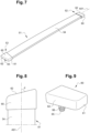
FIG. 6 is a perspective view of a side beam of the bunk, in the normal sate. -
FIG. 7 is a perspective view of an example of a slat pertaining to a supporting structure of the bunk. -
FIG. 8 is a detailed view of an end portion of the slat, showing a cap. -
FIG. 9 is a perspective view of the cap. -
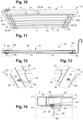
FIG. 10 is a perspective partial view of the bunk from one side and from below. -
FIG. 11 is a side view of the bunk. -
FIG. 12 is an enlarged view of the detail XII offigure 10 . -
FIG. 13 is an enlarged view of the detail XIII offigure 10 . -
FIG. 14 is an enlarged view of the detail XIV offigure 11 . -
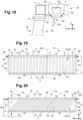
FIG. 15 is a perspective view of the bunk including a base thereof. -
FIG. 16 is an enlarged view of the detail XVI offigure 15 . -
FIG. 17 is a front view corresponding tofigure 16 . -
FIG. 18 is a partial side view of the front part of the bunk and its base. -
FIG. 19 is a top view of the bunk in the normal state. -
FIG. 20 is a top view of the bunk in a collapsed state. -
FIG. 21 is a perspective view of a bunk according to another example, in the normal state. -
FIG. 22 is a top view of the bunk offigure 21 , in the normal state. -
FIG. 23 is a top view of the bunk offigure 21 , in a collapsed state. -
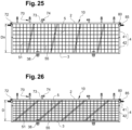
FIG. 24 is a perspective view of a bunk according to still another example, in the normal state. -
FIG. 25 is a top view of the bunk offigure 24 , in the normal state. -
FIG. 26 is a top view of the bunk offigure 24 , in a collapsed state. - Aspects set forth below represent the necessary information to enable those skilled in the art to practice the disclosure.
- The disclosure aims at improving safety for the driver and possible occupants of a vehicle cab in case of a collision. In particular, an aim of the disclosure is to limit or avoid injuries caused by a bunk mounted rearward of the seat(s). To that end, the disclosure provides a bunk the structure of which is collapsible, to prevent the bunk from being pushed forward and reach the cab occupant(s).
-
Figure 1 shows avehicle 100, such as a truck, and more particularly acab 101 of thevehicle 100. Thecab 101 has afront wall 102, twoside walls 103 and arear wall 104. Theside walls 103 each include apillar 105, conventionally referred to as "B pillar". Theside walls 103 further have adoor 106 located between theB pillar 105 and thefront wall 102. Thecab 101 further has afloor 107, and forms adriver compartment 108. Thecab 101 also comprises twoseats 109, one for the driver and one for a possible passenger. - The
cab 101 further comprises abunk 1 which is arranged rearward of theseats 109. Indeed, behind theseats 109, i.e. between theseseats 109 and therear wall 104, there is provided a space which the driver generally uses to store various objects, but also to sleep during the night. - Z is defined as the vertical direction, X is defined as the longitudinal direction of the
vehicle 1, and Y is defined as the transverse direction of thevehicle 1. Thevehicle 100 has e median vertical longitudinal plane P, as shown infigure 1 . - The
bunk 1 comprises aframe 10 formed by afront beam 2 and arear beam 3 which globally extend along the transverse direction Y, andside beams 4 which globally extend along the longitudinal direction X. Said beams can be made of metal, such as steel. Said beams are secured to one another, by welding, by fasteners, or any other appropriate means. In the illustrated example, the beams are substantially straight, so that the frame is rectangular; the front andrear beams frame 10 thus defines aninner surface 5. The term "inner" is used for elements located in or directed towards theinner surface 5, as opposed to the term "outer". Theframe 10 is attached to thecab 101 and, for that purpose, theframe 10 comprises attachments that will be described hereinafter in more detail. - The
bunk 1 also comprises a supportingstructure 50 which is coupled to theframe 10 and extends over theinner surface 5. The supportingstructure 50 aims at supporting a mattress and a bunk occupant. - The
bunk 1 can be in a use position, as illustrated infigures 1 and15 , in which theframe 10 is substantially horizontal, or in a storage position (not shown) which allows easier or even unencumbered access to the area behind theseats 109. Said area may include storage compartments. For example, in the storage position, thebunk 1 may be located against the cabrear wall 104. - Now, the
bunk 1 is described when it is in its use position, and in the normal state, i.e. its state at the first use, while it has not been deformed nor damaged. In such a normal state, thefront beam 2 and therear beam 3 are spaced apart by a nominal distance Dn, along the longitudinal direction X, as shown infigure 19 . - A first example of the
bunk 1 is described with reference tofigures 2 to 20 . - As shown in
figures 3 and 4 , thefront beam 2 and therear beam 3 may comprise aprofile 21, respectively 31, having a square cross-section. Aholder structure 50 may be secured on theinner face front beam 2 and therear beam 3, i.e. the face turned towards theinner surface 5, thus towards the other beam. Theholder lower wall structure 50 can rest. Thelower wall structure 50. In the illustrated example, said attachments are holes which are preferably arranged at regular intervals over the whole length of the front andrear beams lower wall 34 of therear beam 3 may comprisecircular holes 35 having a closed contour while thelower wall 24 of thefront beam 2 may compriseelongated holes 25 which open at the inner edge of thelower wall 24. Theholder 23 of thefront beam 2 can have the shape of a C which is open towards therear beam 3, said holder thus having anupper flange 26 which is substantially horizontal. Thebase portion 27 of theholder 23, which joins thelower wall 24 and theupper flange 26 may be welded to theprofile 21. Theholder 33 of therear beam 3 can be L-shaped, thelower wall 34 forming one wing of theholder 33 and theother wing 37 being welded to theprofile 31. - Each
side beam 4 comprises afront segment 41 having afront end 43 secured to thefront beam 2 and arear segment 42 having arear end 44 secured to therear beam 3. Thefront segment 41 and therear segment 42 extend coaxially along the longitudinal direction X. They are linked to each other, preferably at the rear portion of thefront segment 41 and at the front portion of therear segment 42. In the example offigures 2 to 20 , thefront segment 41 is engaged in therear segment 42 and can slide into it along their common axis A4 which forms a substantially longitudinal sliding direction. Of course, the reverse configuration, with the rear segment being engaged inside the front segment, is possible. Preferably, thesegments front beam 2 and therear beam 3. Thus, eachsegment segments front segment 41 and therear segment 42 substantially have the same length that is higher than half the nominal distance Dn. - At least one
fastener 45 may be provided for maintaining the front andrear segments figure 6 , thefastener 45 can include a rivet, a screw or a pin engaged incorresponding holes 46 of thesegments - The supporting
structure 50 of the first example comprises a plurality ofslats 51 that have an axis A51 and that extend between thefront beam 2 and therear beam 3. Thefront end 52 of eachslat 51 is coupled to thefront beam 2 and therear end 53 of eachslat 51 is coupled to therear beam 3. Theslats 51 extend globally longitudinally between thebeams slats 51 do not extend exactly longitudinally. More precisely, theslats 51 can be angled relative therear beam 3 by an angle α that is different from 90°, and that is for example comprised between 74° and 89° (seefigure 19 ). In other words, angle α is defined between the slat angle A51 and the axis of therear beam 3, which in this example is the transverse direction Y. Moreover, theslats 51 can be not exactly horizontal but slightly bent upwards, as shown infigure 11 . - In the illustrated example, each
slat 51 comprises abar 54 that may have a rectangular cross-section, and acap 60 mounted on each bar end. Thecap 60 can be made of plastic. Thecap 60 forms a cavity into which one end of theslat 51 is housed. Thecap 60 has alower face 61 that rests on thelower wall holder corresponding beam lower face 61 extends acoupler 65 for coupling theslat 51 to thefront beam 2, respectively the rear beam 3.Thecouplers 65 are configured to engage theholes holders beams coupler 65 can protrude vertically downward from the caplower face 61 and can have anannular groove 66 allowing thecoupler 65 to be fixed in the correspondinghole lower wall lower face 61 and thelower wall annular groove 66. As can be seen especially infigures 2 ,14 and19 , thecap 60 at thefront end 52 of eachslat 51 is engaged in theholder 23 of thefront beam 2, between thelower wall 24 and theupper flange 26. In other words, theflange 26 extends above thefront end 52 of theslat 51. - Moreover, the
cap 60 has anend face 62 which is preferably angled relative to the slat axis A51 by an angle β, in the mounted position of thecap 60 on thebar 54. Angle β may be comprised between 60° and 75°, as shown infigure 8 . Moreover, the end faces 62 of oneslat 51 are preferably substantially parallel. - Now is described how the
bunk 1 is secured to thecab 101. - The
bunk 1 may comprisehooks 38 secured to therear beam 3, for example welded to it, and coupled to an organ such as a rod secured to the cabrear wall 104. Said hooks 38 thus form attachments of theframe 10 to thecab 101, especially of the rear part of theframe 10. Said hooks 38 further form an hinge that allows moving thebunk 1 from its use position to its storage position, by a pivoting movement about a transverse axis located above the plane in which thebunk 1 lies in its use position. - The
bunk 1 may further comprise abase 70, as shown infigure 15 . The base 70 can be made of reinforcement bars. - The
base 70 has asupport 71 on which theframe 10 can rest in a use position of thebunk 1. Thesupport 71 hasmounts 72 for being secured to thecab 101. More specifically, thesupport 71 may include or be constituted by a transverse bar on which thefront beam 2 of theframe 10 can rest, as shown infigure 18 . Although infigure 18 theframe 10 is depicted as being directly in contact with thesupport 71, it could be envisaged that theframe 10 rests on an intermediate panel which itself rests on thesupport 71. The ends of thetransverse bar 71 are secured by any appropriate means, such as fasteners, to thecab side walls 103, preferably to theB pillar 105. The base 70 also haspoles 73 extending substantially vertically and downward from thesupport 71. Eachpole 73 is provided at its lower end with amount 74 secured to thecab floor 107. - The
bunk 1 is maintained in the use position by at least one stop arranged on theframe 10 and configured to cooperate with a component secured to thecab 101. In particular, one stop may be provided on at least a side front part of theframe 10. - In the example shown in
figures 2 and15 to 17 , onestop 80 protrudes from eachside beam 4, close to thefront beam 2, substantially transversely and away from theframe 10. Thestop 80 may be in the form of a L-bracket having afirst wing 81 which is secured to theside beam 4, for example by welding, and extends towards theadjacent side wall 103 of thecab 101, and asecond wing 82 which extends downward, for example in a plane (X,Z). Thesecond wing 82 may comprise anopening 83 and ahooked end 84. As best shown infigures 16 and 17 , thestop 80 cooperates with alocker 85 secured to thecab side wall 103, preferably to theB pillar 105, by means of an appropriate member such as a bracket (not shown). More specifically, atab 86 of thelocker 85 is inserted in theopening 83 of the stopsecond wing 82. - The
stop 80 andlocker 85 prevent theframe 10 from moving to the storage position, in particular in case of a roll-over of thevehicle 100. - The
bunk 1 is configured to change from its normal state to a collapsed state, especially in case of a vehicular collision, as will now be described. - Following a crash impact, the
frame 10 is pushed forward. - But the front part of the
frame 10 is prevented from moving forward, so that it does not hit theseats 109 and their occupant(s). This is achieved at least partly by the cooperation between thestop 80 and thelocker 85. Anotherstop 90 may be secured to thefront beam 2 as shown infigures 5 and14 . Thestop 90 may be in the form of a L-bracket having afirst wing 91 which is secured to and under thefront beam 2, for example by welding, and extends substantially horizontally, and asecond wing 92 which extends downward, preferably in a plane (Y,Z). Thesecond wing 92 may comprise anend 94 bent forward. As best shown infigure 18 , thestop 90 is configured to engage thesupport 71 of the base from the rear, thereby preventing a further forward movement of theframe 10 with respect to thecab 101. - As the
front beam 2 is prevented from moving forward, therear beam 3, which is pushed forward, tends to move closer to thefront beam 2. The resulting mechanical strains in theframe 10 lead to the following components being broken: thefasteners 45 between the front andrear segments couplers 65 between theslat 51 and the front andrear beams fasteners 45 and thecouplers 65 are designed to be breakable above a predetermined threshold. In other words, they are frangible components, i.e. they are made intentionally breakable, as part of their operation, to allow thebunk 1 to change to its collapsed state. - The
fasteners 45 being broken, thesegments front beam 2 and therear beam 3 is shortened. - As a consequence, the
slats 51 undergo a tilting movement in the plane of theframe 10 and with respect to their initial globally longitudinal orientation. Owing to the initial slight inclination of theslats 51 with respect to the longitudinal direction X (angle α), theslats 51 automatically tend to move in a direction in which said inclination is accentuated. Furthermore, the angle β of the slat end faces 62 allows guiding the tilting movement of theslats 51. Angles α and β thus ensure an easier movement of theslats 51 further to a collision and, consequently, an easier movement of therear beam 3. - Angles α and β, and the corresponding orientations conferred to the
slats 51 and end faces 62, are consistent with each other. This means that the orientation due to angle α and the orientation due to angle β both tend to move theslat 51 relative to therear beam 3 according to the same pivoting direction. For example, with reference tofigure 19 , the movement of theslats 51 correspond to thefront end 52 of theslat 51 moving towards the right of the figure. - Besides, owing to the
flange 26 of theholder 23 of thefront beam 2, which extends above the front end portion of theslats 51, as best seen infigure 12 , theslats 51 are prevented from moving out of theholder 23, flying off theframe 10 and being projected inside thecab 101. -
Figure 20 shows thebunk 1 in the collapsed state. The front andrear beams front segment 41 engaged further into therear segment 42; theslats 51 are angled relative to therear beam 3 by an angle which may be greater than 40°. Thebunk 1 has not been projected inside thedriver compartment 108 and has not hit theseats 109. Depending on the impact, thebunk 1 may have come into contact with theseats 109, but with a very limited speed unlikely to cause injuries. Theframe 10 has kept its overall shape but has been compressed along the longitudinal direction X. - A second example of the
bunk 1 is described with reference tofigures 21 to 23 . The bunk is substantially identical to the one of the first example except for the side beams 4 which are not telescopic. - As shown in
figures 21 and 22 , in the normal state, thefront segment 41 of eachside beam 4 is pivotally connected to thefront beam 2 by ahinge 47, therear segment 42 of eachside beam 4 is pivotally connected to therear beam 3 by ahinge 48. Moreover, thefront segment 41 and therear segment 42 are pivotally connected to each other by ahinge 49. The hinges 47, 48, 49 define pivoting movements about pivoting axes that are substantially vertical. More specifically, thefront segment 41 and therear segment 42 may be connected to thehinge 49 respectively about afirst pivoting axis 49a and asecond pivoting axis 49b. Thehinge 49 may be located in the middle of theside beam 4, meaning that the front andrear segments front segment 41 and therear segment 42 in the normal state, in which they form a substantially straight andlongitudinal side beam 4. - Thus, when the
bunk 1 changes from its normal state to its collapsed state, thesegments hinge 49 but move from a coaxial position to an angled position, as shown infigure 23 , after the fasteners are broken. The movement of therear beam 3 towards thefront beam 2 results in the side beams 4 forming inwardly directed angles. - A third example of the
bunk 1 is described with reference tofigures 24 to 26 . The bunk is substantially identical to the one of the first example except for the supportingstructure 50. - In the third example, the supporting
structure 50 comprises a net ofwires 55, such as metal wires. In the normal state, the net substantially lies in a horizontal plane, or can be slightly bent upwards. When thebunk 1 changes to its collapsed state, the net is deformed: thewires 55 move closer to each other in the longitudinal direction; they can further be bent. One advantage of this example is that a net may be easier to deform / compress following a collision. - The supporting
structure 50 may also includeslats 51 under the net. Theseslats 51 can be tilted with respect to therear beam 3 after the couplers with the front andrear beams - The terminology used herein is for the purpose of describing particular aspects only and is not intended to be limiting of the disclosure. As used herein, the singular forms "a," "an," and "the" are intended to include the plural forms as well, unless the context clearly indicates otherwise. As used herein, the term "and/or" includes any and all combinations of one or more of the associated listed items. It will be further understood that the terms "comprises," "comprising," "includes," and/or "including" when used herein specify the presence of stated features, integers, steps, operations, elements, and/or components, but do not preclude the presence or addition of one or more other features, integers, steps, operations, elements, components, and/or groups thereof.
- It will be understood that, although the terms first, second, etc., may be used herein to describe various elements, these elements should not be limited by these terms. These terms are only used to distinguish one element from another. For example, a first element could be termed a second element, and, similarly, a second element could be termed a first element without departing from the scope of the present disclosure.
- Relative terms such as "below" or "above" or "upper" or "lower" or "horizontal" or "vertical" may be used herein to describe a relationship of one element to another element as illustrated in the Figures. It will be understood that these terms and those discussed above are intended to encompass different orientations of the device in addition to the orientation depicted in the Figures. It will be understood that when an element is referred to as being "connected" or "coupled" to another element, it can be directly connected or coupled to the other element, or intervening elements may be present. In contrast, when an element is referred to as being "directly connected" or "directly coupled" to another element, there are no intervening elements present.
- Unless otherwise defined, all terms (including technical and scientific terms) used herein have the same meaning as commonly understood by one of ordinary skill in the art to which this disclosure belongs. It will be further understood that terms used herein should be interpreted as having a meaning consistent with their meaning in the context of this specification and the relevant art and will not be interpreted in an idealized or overly formal sense unless expressly so defined herein.
- It is to be understood that the present disclosure is not limited to the aspects described above and illustrated in the drawings; rather, the skilled person will recognize that many changes and modifications may be made within the scope of the present disclosure and appended claims. In the drawings and specification, there have been disclosed aspects for purposes of illustration only and not for purposes of limitation, the scope of the inventive concepts being set forth in the following claims.
Claims (15)
- A bunk (1) for a cab (101) of a vehicle (100), comprising:- a frame (10) having a front beam (2) and a rear beam (3) which globally extend along a transverse direction (Y), and side beams (4) which globally extend along a longitudinal direction (X), said front, rear and side beams (2, 3, 4) being secured to one another, the frame (10) defining an inner surface (5) and further comprising attachments (38, 80) for attaching the frame (10) to the cab (101),- a supporting structure (50) coupled to the frame (10) and extending over the inner surface (5),wherein, in a normal state, the side beams (4) maintain a nominal distance (Dn) between the front and the rear beams (2, 3),each side beam (4) comprising at least a front segment (41) connected to the front beam (2) and a rear segment (42) connected to the rear beam (3), wherein the segments (41, 42) globally extend along the longitudinal direction (X), are linked to each another and have a length smaller than the nominal distance (Dn), the front and rear segments (41, 42) being in a first relative position in the normal state,the bunk (1) being configured to change from its normal state to a collapsed state in which the front and rear beams (2, 3) are spaced apart by a distance (D) that is smaller than the nominal distance (Dn), and in which the front and rear segments (41, 42) remain linked to each another while being in a second relative position different from the first relative position.
- The bunk of claim 1, wherein the front and rear segments (41, 42) are slidably linked to each other along a sliding direction that is substantially longitudinal (X).
- The bunk of claim 1, wherein the front segment (41), respectively the rear segment (42), is pivotally connected to the front beam (2), respectively the rear beam (3), about a pivoting axis that is substantially vertical, the front and rear segments (41, 42) further being pivotally connected to each other about at least one pivoting axis (49a, 49b) that is substantially vertical, whereby in the collapsed state the front and rear segments (41, 42) are angled relative to each other.
- The bunk of any of claims 1 to 3, further comprising fasteners (45) for maintaining the front and rear segments (41, 42) of the side beams (4) in the normal state, said fasteners (45) being breakable above a predetermined threshold, to allow the bunk (1) to change to its collapsed state.
- The bunk of any of claims 1 to 4, wherein the supporting structure (50) comprises slats (51) that extend between the front and the rear beams (2, 3), the front end, respectively the rear end, of each slat (51) being coupled to the front beam (2), respectively the rear beam (3), by a coupler (65) which is breakable above a predetermined threshold.
- The bunk of claim 5, wherein each slat (51) includes a bar (54) and a cap (60) mounted on each bar end, the couplers (65) being arranged on the caps (60).
- The bunk of any of claims 5 to 6, wherein the slat end faces (62) are angled relative to the slat axis (A51), said end faces (62) preferably being substantially parallel.
- The bunk of any of claims 5 to 7, wherein the slats (51) are angled relative to the rear beam (3) by an angle (α) that is comprised between 74° and 89°.
- The bunk of any of claims 1 to 8, wherein the supporting structure (50) comprises a net of wires (55), such as metal wires, which is configured to be deformed when the bunk (1) changes to its collapsed state.
- The bunk of any of claims 1 to 9, wherein at least one beam, preferably one of the front and rear beams (2, 3), comprises a flange (26) extending above an edge of the supporting structure (50) and configured to prevent said supporting structure (50) from moving apart from said beam.
- The bunk of any of claims 1 to 10, further comprising a base (70) having:- a support (71) on which the frame (10) can rest in a use position of the bunk (1), the support (71) comprising mounts (72) for being secured to a cab wall (103),- optionally, at least one pole (73) extending substantially vertically and downward from the support (71) and provided at its lower end with a mount (74) for being secured to a cab floor (107).
- The bunk of any of claims 1 to 11, further comprising at least one stop (80, 90) arranged on the frame (10) and configured to cooperate with a component (85, 70) secured to the cab (101), for preventing the front beam (2) from moving forward in case of a vehicular collision.
- The bunk of any of claims 11 and 12, wherein the or one of the stops (90) is secured to the front beam (2) and is arranged to engage the support (71) of the base (70) from the rear.
- The bunk of any of claims 12 to 13, wherein the or one of the stops (80) protrudes from at least one side beam (4) of from the front beam (2), substantially transversely and away from the frame (10), the stop (80) comprising an attaching portion (83) for being attached to a component (85) secured to a cab side wall (103).
- A vehicle (100) comprising a cab (101) defining a driver compartment (108), the cab (101) including at least one seat (109), the vehicle (100) further comprising the bunk (1) according to any of claims 1-14, said bunk (1) being arranged rearward of the seat (109).
Priority Applications (2)
| Application Number | Priority Date | Filing Date | Title |
|---|---|---|---|
| EP23150598.3A EP4397538B1 (en) | 2023-01-06 | 2023-01-06 | A bunk for a vehicle cab |
| US18/534,601 US12594868B2 (en) | 2023-01-06 | 2023-12-09 | Bunk for a vehicle cab |
Applications Claiming Priority (1)
| Application Number | Priority Date | Filing Date | Title |
|---|---|---|---|
| EP23150598.3A EP4397538B1 (en) | 2023-01-06 | 2023-01-06 | A bunk for a vehicle cab |
Publications (2)
| Publication Number | Publication Date |
|---|---|
| EP4397538A1 true EP4397538A1 (en) | 2024-07-10 |
| EP4397538B1 EP4397538B1 (en) | 2025-11-26 |
Family
ID=84887198
Family Applications (1)
| Application Number | Title | Priority Date | Filing Date |
|---|---|---|---|
| EP23150598.3A Active EP4397538B1 (en) | 2023-01-06 | 2023-01-06 | A bunk for a vehicle cab |
Country Status (2)
| Country | Link |
|---|---|
| US (1) | US12594868B2 (en) |
| EP (1) | EP4397538B1 (en) |
Families Citing this family (2)
| Publication number | Priority date | Publication date | Assignee | Title |
|---|---|---|---|---|
| US20220212593A1 (en) * | 2019-06-25 | 2022-07-07 | Consolidated Metco, Inc. | Sleeper bunk system |
| USD1070446S1 (en) * | 2021-11-30 | 2025-04-15 | Kevin Dunn | Folding bed frame |
Citations (5)
| Publication number | Priority date | Publication date | Assignee | Title |
|---|---|---|---|---|
| EP0168708A1 (en) * | 1984-07-18 | 1986-01-22 | ALUMINIA S.p.A. | Berth or bunk with deformable structure for cabs of industrial vehicles and the like, particularly suitable to reduce the damages to the driver in case of road accidents |
| JPS6215256U (en) * | 1985-07-10 | 1987-01-29 | ||
| EP1516780A2 (en) * | 2003-09-20 | 2005-03-23 | MAN Nutzfahrzeuge Aktiengesellschaft | Day bed for a truck cabin |
| WO2006131634A2 (en) * | 2005-06-08 | 2006-12-14 | Richard Maximilien | Bedframe, bed comprising this frame, and method for fitting a motor vehicle with this bed |
| WO2020222642A1 (en) * | 2019-04-29 | 2020-11-05 | Daf Trucks N.V. | Crash relax bed platform |
Family Cites Families (57)
| Publication number | Priority date | Publication date | Assignee | Title |
|---|---|---|---|---|
| US1377852A (en) * | 1921-05-10 | Terson | ||
| US1125005A (en) * | 1913-03-19 | 1915-01-12 | Oliver O Clark | Baby-carrier for vehicles. |
| US1258694A (en) * | 1917-04-23 | 1918-03-12 | Emma Miller | Field-hospital. |
| US1284651A (en) * | 1918-06-17 | 1918-11-12 | James Almon Gordanier | Collapsible bed for automobiles. |
| US1428642A (en) * | 1920-12-13 | 1922-09-12 | Lambie Charles | Convertible cot and table |
| US1403425A (en) * | 1921-05-16 | 1922-01-10 | John M Line | Cot |
| US1493104A (en) * | 1922-04-03 | 1924-05-06 | Thomas E Carrigan | Knockdown bed frame for automobiles |
| US1545104A (en) * | 1923-04-12 | 1925-07-07 | Frank E Keith | Auto bed |
| US1546581A (en) * | 1923-05-07 | 1925-07-21 | William F Hofford | Luggage carrier |
| US1576919A (en) * | 1924-11-04 | 1926-03-16 | Lowery Cleve | Folding bed for automobiles |
| US2634432A (en) * | 1950-12-15 | 1953-04-14 | Harry L Ehrenberg | Portable and collapsible baby bed |
| US2759199A (en) * | 1953-06-01 | 1956-08-21 | Joy H Wollam | Trunk transportable camping equipment |
| GB1115511A (en) * | 1964-12-23 | 1968-05-29 | John Guythar Bradford | Improvements relating to collapsible supporting structures |
| US3426367A (en) * | 1965-12-21 | 1969-02-11 | John G Bradford | Collapsible supporting structures |
| US3524673A (en) * | 1968-04-08 | 1970-08-18 | Western Sales & Supply Co | Bed for truck cabs |
| US3558180A (en) * | 1969-05-27 | 1971-01-26 | Dean E Algire | Bed attachment for tractor cabs |
| US3601824A (en) * | 1970-03-13 | 1971-08-31 | John G Bradford | Collapsible stretcher having removable bed section |
| US3611452A (en) * | 1970-06-25 | 1971-10-12 | American Hospital Supply Corp | Invalid bed construction |
| US3738705A (en) * | 1972-08-11 | 1973-06-12 | Coleman Co | Convertible bunk bed and lounge chair assembly |
| US3837019A (en) * | 1973-03-12 | 1974-09-24 | J Hoff | Modular cradle-like structure |
| US4044410A (en) * | 1976-08-23 | 1977-08-30 | Holiday Rambler Corporation | Combination bunk bed and seat |
| US4868939A (en) * | 1988-11-22 | 1989-09-26 | Tagtow Jerald C | Free floating bunk bed |
| US4977631A (en) * | 1989-02-13 | 1990-12-18 | Bretz Franklin E | Trucker's bed |
| US5384926A (en) * | 1993-10-20 | 1995-01-31 | Al-Bargi; Hamed H. | Expandable litter apparatus |
| US5638560A (en) * | 1995-12-26 | 1997-06-17 | Rigdon; Charles V. | Sleeper bed for over-the-road tractors |
| US6907632B2 (en) * | 2002-05-28 | 2005-06-21 | Ferno-Washington, Inc. | Tactical stretcher |
| US6932408B1 (en) * | 2004-03-15 | 2005-08-23 | Louis C. Lyod, Jr. | Adjustable frame with seat for a truck bed |
| US7552488B2 (en) * | 2006-08-16 | 2009-06-30 | International Truck Intellectual Property Company, Llc | Restraint device for a bed in a motor vehicle |
| US20090106896A1 (en) * | 2007-02-13 | 2009-04-30 | Rbw Industries, Inc. | Fold-Out Bed Frame |
| US7845034B2 (en) * | 2007-09-21 | 2010-12-07 | Kim Willie W | Articulating bed and method of operating the same |
| US7712168B2 (en) * | 2007-09-21 | 2010-05-11 | Kim Willie W | Articulating bed and method of using the same |
| WO2010068826A2 (en) * | 2008-12-10 | 2010-06-17 | Tac-Evac, Llc | Collapsible litter apparatus, system and method |
| US20100229303A1 (en) * | 2009-03-11 | 2010-09-16 | Aaron Goldsmith | Modular user-assembled adjustable, and high-low adjustable, beds |
| US9713388B2 (en) * | 2009-03-11 | 2017-07-25 | Aaron Goldsmith | Modular user-assembled adjustable, and high-low adjustable beds |
| US8424132B2 (en) * | 2010-09-03 | 2013-04-23 | Cvg Management Corporation | Retractable bunk |
| US8776284B2 (en) * | 2010-11-22 | 2014-07-15 | Allied Recreation Group, Inc. | Moveable bed system |
| US10040387B2 (en) * | 2014-11-10 | 2018-08-07 | Miller O. Johnston | Truck bed cot |
| US11311110B1 (en) * | 2015-10-12 | 2022-04-26 | Michael McDade | Camp bunk bed |
| US10149548B2 (en) * | 2016-01-13 | 2018-12-11 | Alexander L. Ray | Portable bed |
| WO2017171770A1 (en) * | 2016-03-31 | 2017-10-05 | Volvo Truck Corporation | Modular rail and accessory system |
| WO2018102422A1 (en) * | 2016-11-30 | 2018-06-07 | Xstream Trucking Inc. | Deployable fairing for use with vehicles |
| US20190045937A1 (en) * | 2017-08-11 | 2019-02-14 | Connell Reynolds | Collapsable luggage bed |
| WO2019217917A1 (en) * | 2018-05-11 | 2019-11-14 | Adventure Wagon Llc | Telescoping bed platform |
| NL2023023B1 (en) | 2019-04-29 | 2020-11-05 | Daf Trucks Nv | Crash bed platform |
| US11685304B2 (en) * | 2019-06-25 | 2023-06-27 | Consolidated Metco, Inc. | Sleeper bunk system |
| US20220212593A1 (en) * | 2019-06-25 | 2022-07-07 | Consolidated Metco, Inc. | Sleeper bunk system |
| US11180058B2 (en) * | 2019-12-11 | 2021-11-23 | Nikolas Fakhoury | Foldable seating accessory for the trunk of a vehicle |
| DE102020208210A1 (en) | 2020-07-01 | 2022-01-05 | Robert Bosch Gesellschaft mit beschränkter Haftung | Device and method for cleaning the inside of a windshield of a motor vehicle |
| US12036912B2 (en) * | 2021-07-23 | 2024-07-16 | Thor Tech, Inc. | Convertible furniture system and RV comprising the same |
| US12311885B2 (en) * | 2021-10-26 | 2025-05-27 | Orion Outdoors LLC | Adjustable vehicle platform |
| EP4257423A1 (en) * | 2022-04-06 | 2023-10-11 | Volvo Truck Corporation | Truck cabin |
| US20230397738A1 (en) * | 2022-06-08 | 2023-12-14 | Gerardo Torres | Sofa-bed and sofa-bed conversion |
| US11613198B1 (en) * | 2022-07-05 | 2023-03-28 | Robert Howard Carlseen | Space expanding camper bed transformers and kit |
| US12269598B2 (en) * | 2022-08-08 | 2025-04-08 | B/E Aerospace, Inc. | Economy class passenger seat row convertible to bunk beds |
| US20240278708A1 (en) * | 2023-02-20 | 2024-08-22 | Lippert Components, Inc. | Lifts for Recreational Vehicles and Other Structures |
| US20240383392A1 (en) * | 2023-05-16 | 2024-11-21 | Ember Recreational Vehicles, Inc. | Reconfigurable bed system |
| US20240425128A1 (en) * | 2023-06-06 | 2024-12-26 | Eddie Dorszynski | Bed, rack and modular components for vehicles systems |
-
2023
- 2023-01-06 EP EP23150598.3A patent/EP4397538B1/en active Active
- 2023-12-09 US US18/534,601 patent/US12594868B2/en active Active
Patent Citations (5)
| Publication number | Priority date | Publication date | Assignee | Title |
|---|---|---|---|---|
| EP0168708A1 (en) * | 1984-07-18 | 1986-01-22 | ALUMINIA S.p.A. | Berth or bunk with deformable structure for cabs of industrial vehicles and the like, particularly suitable to reduce the damages to the driver in case of road accidents |
| JPS6215256U (en) * | 1985-07-10 | 1987-01-29 | ||
| EP1516780A2 (en) * | 2003-09-20 | 2005-03-23 | MAN Nutzfahrzeuge Aktiengesellschaft | Day bed for a truck cabin |
| WO2006131634A2 (en) * | 2005-06-08 | 2006-12-14 | Richard Maximilien | Bedframe, bed comprising this frame, and method for fitting a motor vehicle with this bed |
| WO2020222642A1 (en) * | 2019-04-29 | 2020-11-05 | Daf Trucks N.V. | Crash relax bed platform |
Also Published As
| Publication number | Publication date |
|---|---|
| US12594868B2 (en) | 2026-04-07 |
| EP4397538B1 (en) | 2025-11-26 |
| US20240227649A1 (en) | 2024-07-11 |
Similar Documents
| Publication | Publication Date | Title |
|---|---|---|
| US12594868B2 (en) | Bunk for a vehicle cab | |
| US20200031303A1 (en) | Vehicle security divider | |
| US20030025358A1 (en) | Vehicle front body structure | |
| US20120080901A1 (en) | Vehicular storage system | |
| US12311856B2 (en) | Connecting element for improved crash behaviour in a car to car collision | |
| JP2007504037A (en) | Dashboard subassembly including glove box door | |
| CN100377925C (en) | System for preventing window from protruding into railway vehicle cab during impact | |
| CA2956376C (en) | Vehicle partition | |
| US5678885A (en) | Vehicle body construction | |
| US7380853B2 (en) | Crash appropriate vehicle partition | |
| EP3962779B1 (en) | Crash relax bed platform | |
| WO2020211704A1 (en) | A foldable vehicle cage system | |
| EP2555964A1 (en) | Combined bunk and storage space for vehicle | |
| US12617247B2 (en) | Tow hook assemblies and vehicles including same | |
| WO2008073026A1 (en) | Bed arrangement for vehicles | |
| WO2000012357A1 (en) | Device for underrun protection in vehicles | |
| US10479411B2 (en) | Structurally reinforced vehicle body | |
| CN108973803B (en) | Automobile side collision occupant protection safety seat and control method thereof | |
| US9689181B2 (en) | Bonnet latch bracket arrangement | |
| EP1900575A2 (en) | Safety bar, particulary for industrial vehicles | |
| GB2456143A (en) | A motor vehicle bumper arrangement | |
| US20220258803A1 (en) | Interior structure for an automated vehicle | |
| JPH07285401A (en) | Automotive bumper | |
| CA2338427C (en) | Truck cab | |
| US10286761B1 (en) | Passenger vehicle door and window |
Legal Events
| Date | Code | Title | Description |
|---|---|---|---|
| PUAI | Public reference made under article 153(3) epc to a published international application that has entered the european phase |
Free format text: ORIGINAL CODE: 0009012 |
|
| STAA | Information on the status of an ep patent application or granted ep patent |
Free format text: STATUS: THE APPLICATION HAS BEEN PUBLISHED |
|
| AK | Designated contracting states |
Kind code of ref document: A1 Designated state(s): AL AT BE BG CH CY CZ DE DK EE ES FI FR GB GR HR HU IE IS IT LI LT LU LV MC ME MK MT NL NO PL PT RO RS SE SI SK SM TR |
|
| STAA | Information on the status of an ep patent application or granted ep patent |
Free format text: STATUS: REQUEST FOR EXAMINATION WAS MADE |
|
| 17P | Request for examination filed |
Effective date: 20241216 |
|
| GRAP | Despatch of communication of intention to grant a patent |
Free format text: ORIGINAL CODE: EPIDOSNIGR1 |
|
| STAA | Information on the status of an ep patent application or granted ep patent |
Free format text: STATUS: GRANT OF PATENT IS INTENDED |
|
| INTG | Intention to grant announced |
Effective date: 20250903 |
|
| GRAS | Grant fee paid |
Free format text: ORIGINAL CODE: EPIDOSNIGR3 |
|
| GRAA | (expected) grant |
Free format text: ORIGINAL CODE: 0009210 |
|
| STAA | Information on the status of an ep patent application or granted ep patent |
Free format text: STATUS: THE PATENT HAS BEEN GRANTED |
|
| AK | Designated contracting states |
Kind code of ref document: B1 Designated state(s): AL AT BE BG CH CY CZ DE DK EE ES FI FR GB GR HR HU IE IS IT LI LT LU LV MC ME MK MT NL NO PL PT RO RS SE SI SK SM TR |
|
| REG | Reference to a national code |
Ref country code: CH Ref legal event code: F10 Free format text: ST27 STATUS EVENT CODE: U-0-0-F10-F00 (AS PROVIDED BY THE NATIONAL OFFICE) Effective date: 20251126 Ref country code: GB Ref legal event code: FG4D |
|
| REG | Reference to a national code |
Ref country code: DE Ref legal event code: R096 Ref document number: 602023008845 Country of ref document: DE |
|
| REG | Reference to a national code |
Ref country code: IE Ref legal event code: FG4D |
|
| REG | Reference to a national code |
Ref country code: NL Ref legal event code: MP Effective date: 20251126 |
|
| PG25 | Lapsed in a contracting state [announced via postgrant information from national office to epo] |
Ref country code: ES Free format text: LAPSE BECAUSE OF FAILURE TO SUBMIT A TRANSLATION OF THE DESCRIPTION OR TO PAY THE FEE WITHIN THE PRESCRIBED TIME-LIMIT Effective date: 20251126 |
|
| REG | Reference to a national code |
Ref country code: LT Ref legal event code: MG9D |
|
| PG25 | Lapsed in a contracting state [announced via postgrant information from national office to epo] |
Ref country code: NO Free format text: LAPSE BECAUSE OF FAILURE TO SUBMIT A TRANSLATION OF THE DESCRIPTION OR TO PAY THE FEE WITHIN THE PRESCRIBED TIME-LIMIT Effective date: 20260226 |
|
| PGFP | Annual fee paid to national office [announced via postgrant information from national office to epo] |
Ref country code: DE Payment date: 20251118 Year of fee payment: 4 |
|
| PG25 | Lapsed in a contracting state [announced via postgrant information from national office to epo] |
Ref country code: FI Free format text: LAPSE BECAUSE OF FAILURE TO SUBMIT A TRANSLATION OF THE DESCRIPTION OR TO PAY THE FEE WITHIN THE PRESCRIBED TIME-LIMIT Effective date: 20251126 Ref country code: HR Free format text: LAPSE BECAUSE OF FAILURE TO SUBMIT A TRANSLATION OF THE DESCRIPTION OR TO PAY THE FEE WITHIN THE PRESCRIBED TIME-LIMIT Effective date: 20251126 Ref country code: AT Free format text: LAPSE BECAUSE OF FAILURE TO SUBMIT A TRANSLATION OF THE DESCRIPTION OR TO PAY THE FEE WITHIN THE PRESCRIBED TIME-LIMIT Effective date: 20251126 |
|
| PGFP | Annual fee paid to national office [announced via postgrant information from national office to epo] |
Ref country code: AT Payment date: 20260301 Year of fee payment: 4 |
|
| REG | Reference to a national code |
Ref country code: AT Ref legal event code: MK05 Ref document number: 1860776 Country of ref document: AT Kind code of ref document: T Effective date: 20251126 |
|
| PG25 | Lapsed in a contracting state [announced via postgrant information from national office to epo] |
Ref country code: NL Free format text: LAPSE BECAUSE OF FAILURE TO SUBMIT A TRANSLATION OF THE DESCRIPTION OR TO PAY THE FEE WITHIN THE PRESCRIBED TIME-LIMIT Effective date: 20251126 |
|
| PG25 | Lapsed in a contracting state [announced via postgrant information from national office to epo] |
Ref country code: RS Free format text: LAPSE BECAUSE OF FAILURE TO SUBMIT A TRANSLATION OF THE DESCRIPTION OR TO PAY THE FEE WITHIN THE PRESCRIBED TIME-LIMIT Effective date: 20260226 |
|
| PG25 | Lapsed in a contracting state [announced via postgrant information from national office to epo] |
Ref country code: IS Free format text: LAPSE BECAUSE OF FAILURE TO SUBMIT A TRANSLATION OF THE DESCRIPTION OR TO PAY THE FEE WITHIN THE PRESCRIBED TIME-LIMIT Effective date: 20260326 |
|
| PG25 | Lapsed in a contracting state [announced via postgrant information from national office to epo] |
Ref country code: PT Free format text: LAPSE BECAUSE OF FAILURE TO SUBMIT A TRANSLATION OF THE DESCRIPTION OR TO PAY THE FEE WITHIN THE PRESCRIBED TIME-LIMIT Effective date: 20260326 |
|
| PG25 | Lapsed in a contracting state [announced via postgrant information from national office to epo] |
Ref country code: PL Free format text: LAPSE BECAUSE OF FAILURE TO SUBMIT A TRANSLATION OF THE DESCRIPTION OR TO PAY THE FEE WITHIN THE PRESCRIBED TIME-LIMIT Effective date: 20251126 |
|
| PG25 | Lapsed in a contracting state [announced via postgrant information from national office to epo] |
Ref country code: LV Free format text: LAPSE BECAUSE OF FAILURE TO SUBMIT A TRANSLATION OF THE DESCRIPTION OR TO PAY THE FEE WITHIN THE PRESCRIBED TIME-LIMIT Effective date: 20251126 |
|
| PG25 | Lapsed in a contracting state [announced via postgrant information from national office to epo] |
Ref country code: BG Free format text: LAPSE BECAUSE OF FAILURE TO SUBMIT A TRANSLATION OF THE DESCRIPTION OR TO PAY THE FEE WITHIN THE PRESCRIBED TIME-LIMIT Effective date: 20251126 |