EP4397529A1 - Linkage device for synchronously controlling multiple lock rods, charging device and motor vehicle - Google Patents
Linkage device for synchronously controlling multiple lock rods, charging device and motor vehicle Download PDFInfo
- Publication number
- EP4397529A1 EP4397529A1 EP22863590.0A EP22863590A EP4397529A1 EP 4397529 A1 EP4397529 A1 EP 4397529A1 EP 22863590 A EP22863590 A EP 22863590A EP 4397529 A1 EP4397529 A1 EP 4397529A1
- Authority
- EP
- European Patent Office
- Prior art keywords
- lock
- rotating shaft
- controlling multiple
- synchronously controlling
- linkage device
- Prior art date
- Legal status (The legal status is an assumption and is not a legal conclusion. Google has not performed a legal analysis and makes no representation as to the accuracy of the status listed.)
- Granted
Links
Images


Classifications
-
- B—PERFORMING OPERATIONS; TRANSPORTING
- B60—VEHICLES IN GENERAL
- B60L—PROPULSION OF ELECTRICALLY-PROPELLED VEHICLES; SUPPLYING ELECTRIC POWER FOR AUXILIARY EQUIPMENT OF ELECTRICALLY-PROPELLED VEHICLES; ELECTRODYNAMIC BRAKE SYSTEMS FOR VEHICLES IN GENERAL; MAGNETIC SUSPENSION OR LEVITATION FOR VEHICLES; MONITORING OPERATING VARIABLES OF ELECTRICALLY-PROPELLED VEHICLES; ELECTRIC SAFETY DEVICES FOR ELECTRICALLY-PROPELLED VEHICLES
- B60L53/00—Methods of charging batteries, specially adapted for electric vehicles; Charging stations or on-board charging equipment therefor; Exchange of energy storage elements in electric vehicles
- B60L53/10—Methods of charging batteries, specially adapted for electric vehicles; Charging stations or on-board charging equipment therefor; Exchange of energy storage elements in electric vehicles characterised by the energy transfer between the charging station and the vehicle
- B60L53/14—Conductive energy transfer
- B60L53/16—Connectors, e.g. plugs or sockets, specially adapted for charging electric vehicles
-
- B—PERFORMING OPERATIONS; TRANSPORTING
- B60—VEHICLES IN GENERAL
- B60L—PROPULSION OF ELECTRICALLY-PROPELLED VEHICLES; SUPPLYING ELECTRIC POWER FOR AUXILIARY EQUIPMENT OF ELECTRICALLY-PROPELLED VEHICLES; ELECTRODYNAMIC BRAKE SYSTEMS FOR VEHICLES IN GENERAL; MAGNETIC SUSPENSION OR LEVITATION FOR VEHICLES; MONITORING OPERATING VARIABLES OF ELECTRICALLY-PROPELLED VEHICLES; ELECTRIC SAFETY DEVICES FOR ELECTRICALLY-PROPELLED VEHICLES
- B60L53/00—Methods of charging batteries, specially adapted for electric vehicles; Charging stations or on-board charging equipment therefor; Exchange of energy storage elements in electric vehicles
- B60L53/30—Constructional details of charging stations
-
- H—ELECTRICITY
- H01—ELECTRIC ELEMENTS
- H01R—ELECTRICALLY-CONDUCTIVE CONNECTIONS; STRUCTURAL ASSOCIATIONS OF A PLURALITY OF MUTUALLY-INSULATED ELECTRICAL CONNECTING ELEMENTS; COUPLING DEVICES; CURRENT COLLECTORS
- H01R13/00—Details of coupling devices of the kinds covered by groups H01R12/70 or H01R24/00 - H01R33/00
- H01R13/62—Means for facilitating engagement or disengagement of coupling parts or for holding them in engagement
- H01R13/629—Additional means for facilitating engagement or disengagement of coupling parts, e.g. aligning or guiding means, levers, gas pressure electrical locking indicators, manufacturing tolerances
-
- H—ELECTRICITY
- H01—ELECTRIC ELEMENTS
- H01R—ELECTRICALLY-CONDUCTIVE CONNECTIONS; STRUCTURAL ASSOCIATIONS OF A PLURALITY OF MUTUALLY-INSULATED ELECTRICAL CONNECTING ELEMENTS; COUPLING DEVICES; CURRENT COLLECTORS
- H01R13/00—Details of coupling devices of the kinds covered by groups H01R12/70 or H01R24/00 - H01R33/00
- H01R13/62—Means for facilitating engagement or disengagement of coupling parts or for holding them in engagement
- H01R13/639—Additional means for holding or locking coupling parts together, after engagement, e.g. separate keylock, retainer strap
-
- Y—GENERAL TAGGING OF NEW TECHNOLOGICAL DEVELOPMENTS; GENERAL TAGGING OF CROSS-SECTIONAL TECHNOLOGIES SPANNING OVER SEVERAL SECTIONS OF THE IPC; TECHNICAL SUBJECTS COVERED BY FORMER USPC CROSS-REFERENCE ART COLLECTIONS [XRACs] AND DIGESTS
- Y02—TECHNOLOGIES OR APPLICATIONS FOR MITIGATION OR ADAPTATION AGAINST CLIMATE CHANGE
- Y02T—CLIMATE CHANGE MITIGATION TECHNOLOGIES RELATED TO TRANSPORTATION
- Y02T10/00—Road transport of goods or passengers
- Y02T10/60—Other road transportation technologies with climate change mitigation effect
- Y02T10/70—Energy storage systems for electromobility, e.g. batteries
-
- Y—GENERAL TAGGING OF NEW TECHNOLOGICAL DEVELOPMENTS; GENERAL TAGGING OF CROSS-SECTIONAL TECHNOLOGIES SPANNING OVER SEVERAL SECTIONS OF THE IPC; TECHNICAL SUBJECTS COVERED BY FORMER USPC CROSS-REFERENCE ART COLLECTIONS [XRACs] AND DIGESTS
- Y02—TECHNOLOGIES OR APPLICATIONS FOR MITIGATION OR ADAPTATION AGAINST CLIMATE CHANGE
- Y02T—CLIMATE CHANGE MITIGATION TECHNOLOGIES RELATED TO TRANSPORTATION
- Y02T10/00—Road transport of goods or passengers
- Y02T10/60—Other road transportation technologies with climate change mitigation effect
- Y02T10/7072—Electromobility specific charging systems or methods for batteries, ultracapacitors, supercapacitors or double-layer capacitors
-
- Y—GENERAL TAGGING OF NEW TECHNOLOGICAL DEVELOPMENTS; GENERAL TAGGING OF CROSS-SECTIONAL TECHNOLOGIES SPANNING OVER SEVERAL SECTIONS OF THE IPC; TECHNICAL SUBJECTS COVERED BY FORMER USPC CROSS-REFERENCE ART COLLECTIONS [XRACs] AND DIGESTS
- Y02—TECHNOLOGIES OR APPLICATIONS FOR MITIGATION OR ADAPTATION AGAINST CLIMATE CHANGE
- Y02T—CLIMATE CHANGE MITIGATION TECHNOLOGIES RELATED TO TRANSPORTATION
- Y02T90/00—Enabling technologies or technologies with a potential or indirect contribution to GHG emissions mitigation
- Y02T90/10—Technologies relating to charging of electric vehicles
- Y02T90/14—Plug-in electric vehicles
Definitions
- the present disclosure relates to the technical field of new energy automobiles, and particularly to a linkage device for synchronously controlling multiple lock rods, a charging device and a motor vehicle.
- the present disclosure aims to provide a linkage device for synchronously controlling multiple lock rods, a charging device and a motor vehicle, so as to overcome the problems in the prior art.
- a linkage structure is provided, so that one driving device can synchronously control two or more actuating mechanisms through the linkage structure, thereby improving the control precision, and effectively reducing the manufacturing cost and the number of sub-parts.
- the present disclosure further provides a charging device, including the aforementioned linkage device for synchronously controlling multiple lock rods.
- the present disclosure further provides a motor vehicle, including the aforementioned linkage device for synchronously controlling multiple lock rods.
- the linkage device for synchronously controlling multiple lock rods, the charging device and the motor vehicle of the present disclosure have the following advantageous effects:
- a linkage structure is designed, so that one driving device can synchronously control two or more actuating mechanisms through the linkage structure, thereby effectively reducing the manufacturing cost, the number of sub-parts, and the difficulty and cost of the assembly process.
- the linkage structure of the present disclosure utilizes the principle of position limiting and chute, uses a lever to change the force direction, thereby driving multiple lock rods to synchronously telescope.
- the present disclosure provides a linkage device 100 for synchronously controlling multiple lock rods, including a driving device 1 having an output end connected to a linkage structure 2.
- the linkage structure 2 is connected to at least two lock rods, and each of the lock rods is used for being connected to a charging gun head.
- the driving device 1 drives, through the linkage structure 2, each of the lock rods to move synchronously.
- the driving device 1 includes, but is not limited to, a motor or an electronic lock, and the linkage structure 2 is connected to an output end of the motor or the electronic lock to realize a torque transmission.
- the movement of the lock rod is one or more selected from telescoping, translation, rotation, swinging, bending and twisting.
- the linkage structure 2 drives at least two lock rods to move, and the mode of movement may be selected according to the actual use environment, as long as the multiple lock rods can be controlled synchronously.
- lock rod is plugged with a keyhole of the charging gun to fix the charging gun.
- the keyhole is prior art and is not illustrated in the figures.
- An important objective of the present disclosure is to lock the charging gun, and each of the lock rods can be inserted into the keyholes of different charging guns for locking, so as to prevent the situation that the charging gun falls off from the charging stand during charging and the charging of the automobile cannot be continued.
- the falling off charging gun which is electriferous, may also cause a risk of electric shock casualties.
- a shape of the lock rod is one or more selected from a circular cylinder, a circular truncated cone, a circular cone, an elliptic cylinder, an elliptic truncated cone, an elliptic cone, a polygonal prism, a polygonal truncated cone and a polygonal cone, which may be selected deepening on the shape of the keyhole of the charging gun during actual use.
- the linkage structure 2 is connected to a first lock rod 3 and a second lock rod 4, which are spatially disposed at a first included angle.
- the first included angle may be determined according to actual use needs, and in a specific embodiment, the two lock rods are spatially perpendicular to each other.
- the first lock rod 3 is used for being connected to a first charging gun head
- the second lock rod 4 is used for being connected to a second charging gun head.
- the first charging gun head and the second charging gun head are of the prior art, and may be the existing charging structures.
- the driving device 1 drives the first lock rod 3 and the second lock rod 4 to move synchronously through the linkage structure 2.
- the first lock rod 3 is an AC lock rod
- the first charging gun head is an AC charging gun head
- the second lock rod 4 is a DC lock rod
- the second charging gun head is a DC charging gun head
- the motor drives the first lock rod 3 and the second lock rod 4 to move synchronously through the linkage structure 2.
- the linkage device 100 for synchronously controlling multiple lock rods of the present disclosure is disposed in a hollow housing (not illustrated in the figures).
- first lock rod 3 and the second lock rod 4 are both actuating mechanisms, so that the first lock rod 3 and the second lock rod 4, which serve as actuating mechanisms, are driven by an output end of the driving device 1 to extend or retract synchronously to act as bolts.
- One driving device 1 can synchronously control two or more actuating mechanisms through the linkage structure 2, thereby effectively reducing the manufacturing cost and the number of sub-parts.
- the linkage structure 2 is disposed, so that one driving device 1 can synchronously control two actuating mechanisms through the linkage structure 2, thereby effectively reducing the manufacturing cost, the number of sub-parts, and the difficulty and cost of the assembly process.
- the linkage structure 2 includes a transmission shaft 20 coaxially disposed with an output end of the driving device 1, and a first end of the transmission shaft 20 is fixedly connected to the output end of the driving device 1.
- the first end of the transmission shaft 20 is provided with a first link rotating shaft 21 which is connected to the first lock rod 3, and the transmission shaft 20 is capable of driving, through the first link rotating shaft 21, the first lock rod 3 to telescope.
- a second end of the transmission shaft 20 is provided with a second link rotating shaft which is connected to the second lock rod 4, and the transmission shaft 20 is capable of driving, through the second link rotating shaft, the second lock rod 4 to telescope.
- the linkage structure 2 drives the first lock rod 3 and the second lock rod 4 to synchronously telescope.
- first lock rod 3 has a length of 5 mm to 55 mm
- second lock rod 4 has a length of 5 mm to 55 mm.
- the inventor selects the length of the first lock rod 3 to be 5 mm to 55 mm and the length of the second lock rod 4 to be 5 mm to55 mm.
- first lock rod has a maximum stroke of 5 mm to 36 mm
- second lock rod has a maximum stroke of 5 mm to 36 mm.
- the inventor uses the first lock rods 3 with different maximum strokes and the second lock rods 4 with different maximum strokes for tests. It is unqualified if the locking cannot be completed or abnormal sound occurs.
- Table 2 The test results are shown in Table 2.
- the inventor selects the maximum stroke of the first lock rod 3 to be 5 mm to 36 mm and the maximum stroke of the second lock rod 4 to be 5 mm to 36 mm.
- the first link rotating shaft 21 is connected to a side wall of the first end of the transmission shaft 20, a central axis of the first link rotating shaft 21 may be disposed in parallel with a central axis of the transmission shaft 20 or may be disposed at any other angle, and the first link rotating shaft 21 is rotatable around the central axis of the transmission shaft 20 along with the transmission shaft 20.
- the linkage structure further includes a lever structure, the first link rotating shaft 21 is rotatably and slidably connected to a first end of the lever structure, and a second end of the lever structure is rotatably and slidably connected to the first lock rod 3.
- the lever structure includes a lever 231 connected to a lever rotating shaft 232, the lever rotating shaft 232 is fixedly disposed and has a central axis parallel with a central axis of the transmission shaft 20, the lever 231 is rotatable around the central axis of the lever rotating shaft 232 (the lever 231 is rotatable around the lever rotating shaft 232), and a rotation direction of the lever 231 is opposite to that of the transmission shaft 20.
- end face of the first end of the lever 231 is disposed as a plane.
- the profile shape of the lever 231 and the mounting position of the lever rotating shaft 232 may be adjusted according to the actual applications, and the outer diameter of the first link rotating shaft 21, and the width and the length of the first chute 233 may be determined according to the actual needs, so that the application range is wide.
- the first end of the transmission shaft 20 is provided with a first connecting plate 201 extending outward radially, and the first link rotating shaft 21 is disposed on the first connecting plate 201.
- a keyway 203 (square groove) is disposed on an end face of the first end of the transmission shaft 20, the output end of the driving device 1 is matched with the keyway 203, and the transmission shaft 20 is connected to the output end of the driving device 1 through the keyway 203.
- the first lock rod 3 includes a first-lock-rod limiting pin 31, one end of the first lock rod 3 is provided with a first rotating shaft 32 having a central axis perpendicular to a central axis of the first-lock-rod limiting pin 31, and the first rotating shaft 32 is rotatably and slidably connected to the second end of the lever.
- a third chute 234 is disposed on a side wall of the second end of the lever 231, the third chute 234 is extended inward from an end face of the second end of the lever 231, and the first rotating shaft 32 rotatably passes through the third chute 234.
- a width direction of the third chute 234 is spatially perpendicular to the central axis of the lever rotating shaft 232, and a width of the third chute 234 is greater than an outer diameter of the first rotating shaft 32.
- connection between the lever 231 and the first link rotating shaft 21 on the transmission shaft 20 and the connection between the lever 231 and the first rotating shaft 32 on the first lock rod 3 change the force direction through the lever, and finally the rotation of the first rotating shaft 32 is converted into a telescopic movement of the first-lock-rod limiting pin 31.
- a bottom of the third chute 234 close to one end of the lever rotating shaft 232 is disposed in an arc-shape.
- one end of the first-lock-rod limiting pin 31 is connected to a third connecting plate 33 disposed in an L-shape, and the first rotating shaft 32 is disposed on the third connecting plate 33.
- the contour shape of the third connecting plate 33 may be adjusted according to the actual applications.
- the second lock rod 4 includes a second-lock-rod limiting pin 41, one end of the second lock rod 4 is provided with a second chute 42, a central axis of the second rotating shaft 22 is perpendicular to a central axis of the second-lock-rod limiting pin 41, the second rotating shaft 22 is rotatably and slidably connected to the second chute 42, a width direction of the second chute 42 is parallel to the central axis of the second-lock-rod limiting pin 41, and a width of the second chute 42 is greater than or equal to an outer diameter of the second rotating shaft 22.
- the rotation of the second rotating shaft 22 is converted into a telescopic movement of the second-lock-rod limiting pin 41.
- first rotating shaft 32 and the second rotating shaft 22 have the same rotation radius, which enables the first lock rod 3 and the second lock rod 4 to lock synchronously.
- one end of the second-lock-rod limiting pin 41 is provided with a second-lock-rod connecting buckle plate 43, one side of which is provided with the second chute 42, and a transition inclined plane is disposed between the second-lock-rod connecting buckle plate 43 and the second-lock-rod limiting pin 41.
- the second end of the transmission shaft 20 is provided with a second connecting plate 202 extending outward radially, and the second rotating shaft 22 is disposed on the second connecting plate 202.
- the diameters of the lock rods of the first-lock-rod limiting pin 31 and the second-lock-rod limiting pin 41 are determined according to actual needs, and the settings of each hinge point and each moment arm in the linkage structure 2 are determined according to actual needs.
- the output torque of the driving device 1 determines the magnitude of the force applied to the transmission shaft 20. If the torque is not enough, the first lock rod 3 and the second lock rod 4 cannot be driven to work.
- the test method is to select the driving devices 1 with different output torques, and the other structures of the linkage device are the same. It is qualified if the driving device 1 can normally drive the transmission shaft 20 to work, otherwise it is unqualified, and it is also unqualified if abnormal sound occurs in the linkage device during work. The test results are shown in Table 4.
- the material of the transmission shaft 20 includes one or more selected from the group consisting of polyvinyl chloride, polyethylene, polyamide, polytetrafluoroethylene, tetrafluoroethylene/hexafluoropropylene copolymer, ethylene/tetrafluoroethylene copolymer, polypropylene, polyvinylidene fluoride, polyurethane, polyterephthalic acid, polyurethane elastomer, styrene block copolymer, perfluoroalkoxy alkane, chlorinated polyethylene, polyphenylene sulfide, polystyrene, crosslinked polyolefin, ethylene/vinyl acetate copolymer, crosslinked polyethylene, polycarbonate, polysulfone, polyphenylene oxide, polyester, phenolic resin, urea-formaldehyde, styrene-acrylonitrile copolymer, polymethacrylate, and polyformaldehyde resin
- Polyester is generally made of terephthalic acid and butanediol, and has chain segments including a hard segment and a soft segment, and polyester is a thermoplastic elastomer.
- the inventor selects that the material of the plating layer is selected from one or more from gold, silver, nickel, tin, tin-lead alloy, zinc, hard silver, silver-antimony alloy, palladium, palladium-nickel alloy, graphite silver, graphene silver and silver-gold-zirconium alloy.
Landscapes
- Engineering & Computer Science (AREA)
- Power Engineering (AREA)
- Transportation (AREA)
- Mechanical Engineering (AREA)
- Transmission Devices (AREA)
- Lock And Its Accessories (AREA)
- Electric Propulsion And Braking For Vehicles (AREA)
Abstract
Description
- The present disclosure claims priority to
Chinese Invention Patent Application No. 202111028187.2, entitled `linkage device for synchronously controlling multiple lock rods, charging device and motor vehicle', and filed on September 2, 2021 - The present disclosure relates to the technical field of new energy automobiles, and particularly to a linkage device for synchronously controlling multiple lock rods, a charging device and a motor vehicle.
- The battery electric vehicle among the new energy automobiles is an automobile that uses a single battery as an energy storage power source and provides electric energy to a motor through a battery to drive the motor to run, thereby promoting the automobile to travel. Rechargeable batteries of the pure electric automobile mainly include a lead-acid battery, a nickel-cadmium battery, a nickel-hydrogen battery, a lithium-ion battery, etc., which can provide power for the electric automobile. Meanwhile, the pure electric automobile also stores electric energy through the battery to drive the motor to run and enable the automobile to travel normally. The battery of the pure electric automobile is mainly charged by a charging gun of the new energy automobile.
- In the existing charging technologies, when multiple charging interfaces, e.g., DC and AC charging interfaces, are distributed in a charging stand, it is possible to use different charging guns for charging. In the existing technical solutions, multiple driving devices are used to respectively control the lock connections between the multiple charging interfaces and the charging guns, and each driving device drives a corresponding lock rod to lock and connect the charging gun to a corresponding charging stand for charging, which causes the problems of large number of parts of the driving device and high manufacturing cost.
- Therefore, in the technical field of new energy automobiles, there is an urgent need for a linkage device for synchronously controlling multiple lock rods, a charging device and a motor vehicle, in which one driving device can be used to simultaneously control multiple lock rods to lock and connect a charging gun, thereby overcoming the defects of the prior art and solving the problems of large number of parts of the driving device and high manufacturing cost.
- The present disclosure aims to provide a linkage device for synchronously controlling multiple lock rods, a charging device and a motor vehicle, so as to overcome the problems in the prior art. In the linkage device for synchronously controlling multiple lock rods of the present disclosure, a linkage structure is provided, so that one driving device can synchronously control two or more actuating mechanisms through the linkage structure, thereby improving the control precision, and effectively reducing the manufacturing cost and the number of sub-parts.
- The present disclosure provides a linkage device for synchronously controlling multiple lock rods, including a driving device having an output end connected to a linkage structure, the linkage structure being connected to at least two lock rods, and the driving device driving, through the linkage structure, each of the lock rods to move synchronously.
- The present disclosure further provides a charging device, including the aforementioned linkage device for synchronously controlling multiple lock rods.
- The present disclosure further provides a motor vehicle, including the aforementioned linkage device for synchronously controlling multiple lock rods.
- Based on the above content, the linkage device for synchronously controlling multiple lock rods, the charging device and the motor vehicle of the present disclosure have the following advantageous effects:
- In the linkage device for synchronously controlling multiple lock bars of the present disclosure, a linkage structure is designed, so that one driving device can synchronously control two or more actuating mechanisms through the linkage structure, thereby effectively reducing the manufacturing cost, the number of sub-parts, and the difficulty and cost of the assembly process.
- The linkage structure of the present disclosure utilizes the principle of position limiting and chute, uses a lever to change the force direction, thereby driving multiple lock rods to synchronously telescope.
- All parts in the linkage structure of the present disclosure are simple in structure, convenient to manufacture and beneficial to popularization and use.
- For a clearer illustration of technical features in the embodiments of the present disclosure, a brief description of the drawings for the embodiments of the present disclosure will be given below. Obviously, the drawings described below involve only some embodiments of this disclosure. For those of ordinary skill in the art, other drawings can be derived from these drawings without any inventive efforts. In the drawings: In the drawings,
-
FIG. 1 illustrates a schematic diagram of a linkage device for synchronously controlling multiple lock rods of the present disclosure. -
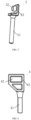
FIG. 2 illustrates a structural diagram of a transmission shaft of the present disclosure. -
FIG. 3 illustrates a schematic diagram of an end face of a first end of a transmission shaft of the present disclosure. -
FIG. 4 illustrates a structural diagram of a lever of the present disclosure. -
FIG. 5 illustrates a structural diagram of a first lock rod of the present disclosure. -
FIG. 6 illustrates a structural diagram of a second lock rod of the present disclosure. - For a clearer understanding of the objectives, technical features and effects of the present disclosure, specific embodiments will now be described with reference to the drawings.
- The specific embodiments of the present disclosure described here are intended to explain the present disclosure and do not limit the scope of the present disclosure. Under the teaching of the present disclosure, persons skilled in the art can conceive any possible variation based on the present disclosure, which should be regarded as falling within the scope of the present disclosure. It should be noted that when an element is referred to as being 'disposed' on another element, it may be directly on another element or there may be an intervening element. When an element is regarded as being 'connected' to another element, it may be directly connected to another element or there may be an intervening element at the same time. The terms 'mount' and 'connect' should be understood in a broad sense. For example, a connection may be a mechanical connection or an electrical connection, or an internal communication between two elements, or a direct connection, or an indirect connection through an intermediate medium. For those of ordinary skill in the art, the specific meanings of the above terms can be understood according to the specific conditions. The terms 'vertical', 'horizontal', 'upper', 'lower', 'left', 'right' and similar expressions used herein are for an illustration purpose only rather than indicating a unique embodiment.
- Unless otherwise defined, all technical and scientific terms used herein have the same meanings as those commonly understood by those of ordinary skilled in the art of the present disclosure. The terms used in the Specification of the present disclosure are only for the purpose of describing the specific embodiments, rather than limiting the present disclosure. The term 'and/or' used herein includes any and all combinations of one or more of the related items listed.
- As illustrated in
FIGS. 1 to 6 , the present disclosure provides alinkage device 100 for synchronously controlling multiple lock rods, including a driving device 1 having an output end connected to alinkage structure 2. Thelinkage structure 2 is connected to at least two lock rods, and each of the lock rods is used for being connected to a charging gun head. The driving device 1 drives, through thelinkage structure 2, each of the lock rods to move synchronously. The driving device 1 includes, but is not limited to, a motor or an electronic lock, and thelinkage structure 2 is connected to an output end of the motor or the electronic lock to realize a torque transmission. - Further, the movement of the lock rod is one or more selected from telescoping, translation, rotation, swinging, bending and twisting. The
linkage structure 2 drives at least two lock rods to move, and the mode of movement may be selected according to the actual use environment, as long as the multiple lock rods can be controlled synchronously. - Further, the lock rod is plugged with a keyhole of the charging gun to fix the charging gun. The keyhole is prior art and is not illustrated in the figures.
- An important objective of the present disclosure is to lock the charging gun, and each of the lock rods can be inserted into the keyholes of different charging guns for locking, so as to prevent the situation that the charging gun falls off from the charging stand during charging and the charging of the automobile cannot be continued. In addition, the falling off charging gun, which is electriferous, may also cause a risk of electric shock casualties.
- In a specific embodiment, a shape of the lock rod is one or more selected from a circular cylinder, a circular truncated cone, a circular cone, an elliptic cylinder, an elliptic truncated cone, an elliptic cone, a polygonal prism, a polygonal truncated cone and a polygonal cone, which may be selected deepening on the shape of the keyhole of the charging gun during actual use.
- In a specific embodiment, the
linkage structure 2 is connected to a first lock rod 3 and asecond lock rod 4, which are spatially disposed at a first included angle. The first included angle may be determined according to actual use needs, and in a specific embodiment, the two lock rods are spatially perpendicular to each other. The first lock rod 3 is used for being connected to a first charging gun head, and thesecond lock rod 4 is used for being connected to a second charging gun head. The first charging gun head and the second charging gun head are of the prior art, and may be the existing charging structures. The driving device 1 drives the first lock rod 3 and thesecond lock rod 4 to move synchronously through thelinkage structure 2. In this embodiment, the first lock rod 3 is an AC lock rod, the first charging gun head is an AC charging gun head, thesecond lock rod 4 is a DC lock rod, the second charging gun head is a DC charging gun head, and the motor drives the first lock rod 3 and thesecond lock rod 4 to move synchronously through thelinkage structure 2. - In practical applications, the
linkage device 100 for synchronously controlling multiple lock rods of the present disclosure is disposed in a hollow housing (not illustrated in the figures). - In a specific embodiment, the first lock rod 3 and the
second lock rod 4 are both actuating mechanisms, so that the first lock rod 3 and thesecond lock rod 4, which serve as actuating mechanisms, are driven by an output end of the driving device 1 to extend or retract synchronously to act as bolts. One driving device 1 can synchronously control two or more actuating mechanisms through thelinkage structure 2, thereby effectively reducing the manufacturing cost and the number of sub-parts. - In the linkage device for synchronously controlling multiple lock rods of the present disclosure, the
linkage structure 2 is disposed, so that one driving device 1 can synchronously control two actuating mechanisms through thelinkage structure 2, thereby effectively reducing the manufacturing cost, the number of sub-parts, and the difficulty and cost of the assembly process. - Further, as illustrated in
FIGS. 1 and 2 , thelinkage structure 2 includes atransmission shaft 20 coaxially disposed with an output end of the driving device 1, and a first end of thetransmission shaft 20 is fixedly connected to the output end of the driving device 1. The first end of thetransmission shaft 20 is provided with a firstlink rotating shaft 21 which is connected to the first lock rod 3, and thetransmission shaft 20 is capable of driving, through the firstlink rotating shaft 21, the first lock rod 3 to telescope. A second end of thetransmission shaft 20 is provided with a second link rotating shaft which is connected to thesecond lock rod 4, and thetransmission shaft 20 is capable of driving, through the second link rotating shaft, thesecond lock rod 4 to telescope. Thelinkage structure 2 drives the first lock rod 3 and thesecond lock rod 4 to synchronously telescope. - Further, the first lock rod 3 has a length of 5 mm to 55 mm, and the
second lock rod 4 has a length of 5 mm to 55 mm. - If the first lock rod 3 and the
second lock rod 4 are too short, the locking cannot be completed, and if the first lock rod 3 and thesecond lock rod 4 are too long, they will interfere with the charging gun to generate abnormal sound. Therefore, the inventor uses the first lock rods 3 with different lengths and thesecond lock rods 4 with different lengths for tests. It is unqualified if the locking cannot be completed or abnormal sound occurs. The test results are shown in Table 1.Table 1: Influence of different lengths of the lock rod on the locking Length of the lock rod (mm) 4 5 8 11 16 21 28 39 47 52 55 56 Whether locking can be completed No Yes Yes Yes Yes Yes Yes Yes Yes Yes Yes Yes Whether abnormal sound occurs No No No No No No No No No No No Yes - As can be seen from Table 1, when the length of the lock rod is less than 5 mm, the lock rod cannot lock the charging gun, and when the length of the lock rod is greater than 55 mm, the lock rod will interfere with the charging gun and generate abnormal sound. Therefore, the inventor selects the length of the first lock rod 3 to be 5 mm to 55 mm and the length of the
second lock rod 4 to be 5 mm to55 mm. - Further, the first lock rod has a maximum stroke of 5 mm to 36 mm, and the second lock rod has a maximum stroke of 5 mm to 36 mm.
- Similarly, if the maximum strokes of the first lock rod 3 and the
second lock rod 4 are too short, the first lock rod 3 and thesecond lock rod 4 cannot lock the charging gun, and if the maximum strokes are too long, the first lock rod 3 and thesecond lock rod 4 will interfere with the charging gun to generate abnormal sound. Therefore, the inventor uses the first lock rods 3 with different maximum strokes and thesecond lock rods 4 with different maximum strokes for tests. It is unqualified if the locking cannot be completed or abnormal sound occurs. The test results are shown in Table 2.Table 2: Influence of different maximum strokes of the lock rod on the locking Maximum stroke (mm) 4 5 8 10 12 15 19 23 28 32 36 38 Whether locking can be completed No Yes Yes Yes Yes Yes Yes Yes Yes Yes Yes Yes Whether abnormal sound occurs No No No No No No No No No No No Yes - As can be seen from Table 2, when the maximum stroke of the lock rod is less than 5 mm, the locking cannot be completed, and when the maximum stroke of the lock rod is greater than 36 mm, abnormal sound will occur. Therefore, the inventor selects the maximum stroke of the first lock rod 3 to be 5 mm to 36 mm and the maximum stroke of the
second lock rod 4 to be 5 mm to 36 mm. - Further, as illustrated in
FIG. 2 , the firstlink rotating shaft 21 is connected to a side wall of the first end of thetransmission shaft 20, a central axis of the firstlink rotating shaft 21 may be disposed in parallel with a central axis of thetransmission shaft 20 or may be disposed at any other angle, and the firstlink rotating shaft 21 is rotatable around the central axis of thetransmission shaft 20 along with thetransmission shaft 20. The linkage structure further includes a lever structure, the firstlink rotating shaft 21 is rotatably and slidably connected to a first end of the lever structure, and a second end of the lever structure is rotatably and slidably connected to the first lock rod 3. - Further, as illustrated in
FIGS. 1 and4 , the lever structure includes alever 231 connected to alever rotating shaft 232, thelever rotating shaft 232 is fixedly disposed and has a central axis parallel with a central axis of thetransmission shaft 20, thelever 231 is rotatable around the central axis of the lever rotating shaft 232 (thelever 231 is rotatable around the lever rotating shaft 232), and a rotation direction of thelever 231 is opposite to that of thetransmission shaft 20. - Further, as illustrated in
FIGS. 1 and4 , thelever 231 is disposed in an elongated shape, and afirst chute 233 is disposed on a side wall of the first end of thelever 231. Thefirst chute 233 is extended inward from an end face of the first end of thelever 231, and the firstlink rotating shaft 21 rotatably and slidably passes through thefirst chute 233. A width direction of thefirst chute 233 is spatially perpendicular to the central axis of thelever rotating shaft 232, and a width of thefirst chute 233 is greater than or equal to an outer diameter of the firstlink rotating shaft 21. - Further, a bottom of the
first chute 233 close to one end of thelever rotating shaft 232 is disposed in an arc-shape. The contour shape of thefirst chute 233 may be adjusted according to actual needs. - Further, the end face of the first end of the
lever 231 is disposed as a plane. - The profile shape of the
lever 231 and the mounting position of thelever rotating shaft 232 may be adjusted according to the actual applications, and the outer diameter of the firstlink rotating shaft 21, and the width and the length of thefirst chute 233 may be determined according to the actual needs, so that the application range is wide. - Further, as illustrated in
FIG. 2 , the first end of thetransmission shaft 20 is provided with a first connectingplate 201 extending outward radially, and the firstlink rotating shaft 21 is disposed on the first connectingplate 201. - Further, as illustrated in
FIG. 3 , a keyway 203 (square groove) is disposed on an end face of the first end of thetransmission shaft 20, the output end of the driving device 1 is matched with thekeyway 203, and thetransmission shaft 20 is connected to the output end of the driving device 1 through thekeyway 203. - Further, as illustrated in
FIGS. 1 and5 , the first lock rod 3 includes a first-lock-rod limiting pin 31, one end of the first lock rod 3 is provided with a firstrotating shaft 32 having a central axis perpendicular to a central axis of the first-lock-rod limiting pin 31, and the firstrotating shaft 32 is rotatably and slidably connected to the second end of the lever. - Further, as illustrated in
FIG. 5 , athird chute 234 is disposed on a side wall of the second end of thelever 231, thethird chute 234 is extended inward from an end face of the second end of thelever 231, and the firstrotating shaft 32 rotatably passes through thethird chute 234. A width direction of thethird chute 234 is spatially perpendicular to the central axis of thelever rotating shaft 232, and a width of thethird chute 234 is greater than an outer diameter of the firstrotating shaft 32. The connection between thelever 231 and the firstlink rotating shaft 21 on thetransmission shaft 20 and the connection between thelever 231 and the firstrotating shaft 32 on the first lock rod 3 change the force direction through the lever, and finally the rotation of the firstrotating shaft 32 is converted into a telescopic movement of the first-lock-rod limiting pin 31. - Further, a bottom of the
third chute 234 close to one end of thelever rotating shaft 232 is disposed in an arc-shape. - Further, as illustrated in
FIG. 5 , one end of the first-lock-rod limiting pin 31 is connected to a third connectingplate 33 disposed in an L-shape, and the firstrotating shaft 32 is disposed on the third connectingplate 33. The contour shape of the third connectingplate 33 may be adjusted according to the actual applications. - Further, as illustrated in
FIGS. 1 and 2 , the second link rotating shaft includes a secondrotating shaft 22 connected to a side wall of the second end of thetransmission shaft 20, a central axis of the secondrotating shaft 22 is disposed in parallel with a central axis of thetransmission shaft 20, the secondrotating shaft 22 is rotatable around the central axis of thetransmission shaft 20 along with thetransmission shaft 20, and the secondrotating shaft 22 is rotatably and slidably connected to the first end of thesecond lock rod 4. - Further, as illustrated in
FIG. 6 , thesecond lock rod 4 includes a second-lock-rod limiting pin 41, one end of thesecond lock rod 4 is provided with asecond chute 42, a central axis of the secondrotating shaft 22 is perpendicular to a central axis of the second-lock-rod limiting pin 41, the secondrotating shaft 22 is rotatably and slidably connected to thesecond chute 42, a width direction of thesecond chute 42 is parallel to the central axis of the second-lock-rod limiting pin 41, and a width of thesecond chute 42 is greater than or equal to an outer diameter of the secondrotating shaft 22. Through the connection between thesecond lock rod 4 and the secondrotating shaft 22, the rotation of the secondrotating shaft 22 is converted into a telescopic movement of the second-lock-rod limiting pin 41. - Further, the first
rotating shaft 32 and the secondrotating shaft 22 have the same rotation radius, which enables the first lock rod 3 and thesecond lock rod 4 to lock synchronously. - Further, the
second chute 42 is disposed in a rectangle, a parallelogram, a polygon, a trapezoid, a rhombus or an oblong shape. - Further, as illustrated in
FIG. 6 , one end of the second-lock-rod limiting pin 41 is provided with a second-lock-rod connectingbuckle plate 43, one side of which is provided with thesecond chute 42, and a transition inclined plane is disposed between the second-lock-rod connectingbuckle plate 43 and the second-lock-rod limiting pin 41. - Further, as illustrated in
FIG. 2 , the second end of thetransmission shaft 20 is provided with a second connectingplate 202 extending outward radially, and the secondrotating shaft 22 is disposed on the second connectingplate 202. - The diameters of the lock rods of the first-lock-
rod limiting pin 31 and the second-lock-rod limiting pin 41 are determined according to actual needs, and the settings of each hinge point and each moment arm in thelinkage structure 2 are determined according to actual needs. - The working process of the linkage device for synchronously controlling multiple lock rods of the present disclosure is as follows:
- a torque is input by the driving device 1 (motor), the
transmission shaft 20 is connected to the output end of the driving device 1 through thekeyway 203, and the output end of the driving device 1 drives thetransmission shaft 20 to rotate through thekeyway 203; - the first
link rotating shaft 21 and the secondrotating shaft 22 rotate around the central axis of thetransmission shaft 20 along with thetransmission shaft 20; - the first
link rotating shaft 21 rotatably passes through thefirst chute 233, the firstlink rotating shaft 21 drives thelever 231 to rotate around the central axis of thelever rotating shaft 232, and the rotation direction of thelever 231 is opposite to that of the firstlink rotating shaft 21; - the first
rotating shaft 32 on the first lock rod 3 rotatably passes through thethird chute 234, and the rotation of thelever 231 drives the first-lock-rod limiting pin 31 to telescope (move along the central axis of the first-lock-rod limiting pin 31), thereby completing the extending and retracting of the first lock rod 3; and - the second
rotating shaft 22 rotatably and slidably passes through thesecond chute 42, and the rotation of the secondrotating shaft 22 drives the second-lock-rod limiting pin 41 to telescope (move along the central axis of the second-lock-rod limiting pin 41), thereby completing the extending and retracting of thesecond lock rod 4. - In some embodiments, the driving device 1 has an output power of 0.35 W to 5.56 W.
- The output power of the driving device 1 determines the working speed of the linkage device, i.e., the larger the power, the faster the linkage device works, and as the power decreases, the linkage device works slower and even the rotation torque of the
transmission shaft 20 is insufficient to complete the locking by the first lock rod 3 and thesecond lock rod 4. In order to test the influence of the output power on the work of the linkage device, the inventor carries out relevant tests. The test method is to select the driving devices 1 with different output power, and the linkage devices of the same structure, wherein each of the driving devices 1 works continuously for 1 minute, and then the number of times of work completion by the linkage device is recorded. If the number of times is greater than or equal to 40, it is qualified, otherwise it is unqualified. If abnormal sound occurs during the working of the linkage device, it is also unqualified. The results are shown in Table 3.Table 3: Influence of different output power on the speed of the linkage device and the abnormal sound Power (W) 0.3 0.35 0.50 0.80 1.13 1.22 1.39 1.75 2.41 3.68 4.86 5.56 5.60 Number of times of completion 38 40 47 52 55 58 61 63 65 66 70 71 71 Whether there is abnormal sound No No No No No No No No No No No No Yes - As shown in Table 3, when the output power of the driving device 1 is less than 0.35 W, the number of times of locking or unlocking completed by the linkage device is less than 40 in one minute, and the speed is too slow to be qualified, so the inventor selects the minimum power of the driving device 1 to be 0.35 W. When the output power of the driving device 1 is greater than 5.56 W, due to the overall design, the speed of the linkage device enters a bottleneck period without an obvious improvement, and abnormal noise occurs at the same time, so the inventor selects the output power of the driving device 1 to be 0.35 W to 5.56 W. Specifically, the output power may be 0.9 W, 0.96 W, 1 W, or 1.08 W.
- In some embodiments, the driving device 1 has an output end which has an output torque of 2.25 N·mm to 9.85 N·mm.
- The output torque of the driving device 1 determines the magnitude of the force applied to the
transmission shaft 20. If the torque is not enough, the first lock rod 3 and thesecond lock rod 4 cannot be driven to work. In order to verify the influence of different output torques of the driving device 1 on the locking or unlocking of the linkage device, the inventor carries out relevant tests. The test method is to select the driving devices 1 with different output torques, and the other structures of the linkage device are the same. It is qualified if the driving device 1 can normally drive thetransmission shaft 20 to work, otherwise it is unqualified, and it is also unqualified if abnormal sound occurs in the linkage device during work. The test results are shown in Table 4.Table 4: Whether driving device 1 with different torques can normally drive the transmission shaft 20 to workTorque (N·mm) 2.15 2.25 3.0 3.6 3.9 4.5 5 5.5 6 7.4 8.6 9.85 10 Whether work is possible No Yes Yes Yes Yes Yes Yes Yes Yes Yes Yes Yes Yes Whether abnormal sound occurs No No No No No No No No No No No No Yes - As shown in Table 4, when the output torque of the driving device 1 is less than 2.25 N·mm, the
transmission shaft 20 cannot be driven to work, so the inventor selects the minimum output torque of the driving device 1 to be 2.25 N·mm. When the output torque is greater than 9.85 N·mm, although thetransmission shaft 20 can be driven to work, abnormal sound occurs when the linkage device works because the output torque is too large, so the inventor selects the output torque of the driving device 1 to be 2.25 N·mm to 9.85 N·mm. Specifically, the output torque may be 3.5 N·mm or 4 N·mm. - In some embodiments, the
transmission shaft 20 has a rotation angle of 15° to 92°. - The rotation angle of the
transmission shaft 20 can also determine the strokes of the first lock rod 3 and thesecond lock rod 4. When the rotation angle of thetransmission shaft 20 is too small, the strokes of the first lock rod 3 and thesecond lock rod 4 are not enough, and the locking cannot be completed. When the rotation angle of thetransmission shaft 20 is too large, after the first lock rod 3 and thesecond lock rod 4 extend to the working positions, thetransmission shaft 20 is still outputting a rotation force, which easily leads to the damage of the linkage device. In order to verify the influence of the rotation angle of thetransmission shaft 20 on the linkage device, the inventor carries out tests. The test method is to use the drive devices 1 with thetransmission shafts 20 of different rotation angles, and the other structures of the linkage device are the same. It is qualified when the strokes of the first lock rod 3 and thesecond lock rod 4 enable locking to be completed, otherwise it is unqualified. A larger rotation angle means larger strokes of the first lock rod 3 and thesecond lock rod 4, which correspondingly requires an increase in the size of each connecting parts and accordingly, thus easily leading to a touch with other components in the linkage device and thus affecting the use of the linkage device, so that the rotation angle of thetransmission shaft 20 in this case is also considered unqualified. The test results are shown in Table 5.Table 5: Influence of different rotation angles of the transmission shaft on the function of the linkage device and the touch with other components Rotation angle 14 15 28 36 47 55 61 70 78 83 89 92 93 Whether locked No Yes Yes Yes Yes Yes Yes Yes Yes Yes Yes Yes Yes Whether touched No No No No No No No No No No No No Yes - As can be seen from Table 5, when the rotation angle of the
transmission shaft 20 is less than 15°, the strokes of the first lock rod 3 and thesecond lock rod 4 are not enough, and the locking cannot be completed. When the rotation angle of thetransmission shaft 20 is greater than 92°, there will be unnecessary contact between the components of the linkage device, which generates abnormal sound and is unqualified. Therefore, the inventor selects the rotation angle of the output end of thetransmission shaft 20 to be 15° to 92°. Specifically, the rotation angle may be 50°, 60°, 70° or 80°. - Further, the
transmission shaft 20 is made of a material including metal or non-metal. - Further, the material of the
transmission shaft 20 includes carbon steel, mere copper, pure copper, aluminum-clad zinc, aluminum-clad copper or zinc alloy. These metals or alloys have better strength and toughness, which can better meet the needs of the transmission shaft. - Further, the material of the
transmission shaft 20 includes one or more selected from the group consisting of polyvinyl chloride, polyethylene, polyamide, polytetrafluoroethylene, tetrafluoroethylene/hexafluoropropylene copolymer, ethylene/tetrafluoroethylene copolymer, polypropylene, polyvinylidene fluoride, polyurethane, polyterephthalic acid, polyurethane elastomer, styrene block copolymer, perfluoroalkoxy alkane, chlorinated polyethylene, polyphenylene sulfide, polystyrene, crosslinked polyolefin, ethylene/vinyl acetate copolymer, crosslinked polyethylene, polycarbonate, polysulfone, polyphenylene oxide, polyester, phenolic resin, urea-formaldehyde, styrene-acrylonitrile copolymer, polymethacrylate, and polyformaldehyde resin. - Taking polyformaldehyde, polyester, polycarbonate, polyamide, polyphenylene sulfide and polytetrafluoroethylene as examples: polyformaldehyde is a hard and dense material with a smooth and shiny surface, and is yellowish or white in color and can be used for a long time in a temperature range of -40°
Cto 100°C. Polyformaldehyde has a wear resistance and a self-lubrication superior to those of most engineering plastics, and also has good oil resistance and peroxide resistance. - Polyester is generally made of terephthalic acid and butanediol, and has chain segments including a hard segment and a soft segment, and polyester is a thermoplastic elastomer.
- Polycarbonate has high strength and elastic coefficient, high impact strength, good fatigue resistance, good dimensional stability, small creep, high transparency and free chromaticity.
- Polyamide is nontoxic and light, with an excellent mechanical strength and good wear resistance and corrosion resistance. Polyamide can be used to replace metals such as copper to manufacture parts such as bearings, gears and pump blades in the industries of machinery, chemicals, instruments, automobiles or the like.
- Polyphenylene sulfide is a new high-performance thermoplastic resin, which has the advantages of high mechanical strength, high temperature resistance, chemical resistance, flame retardancy, good thermal stability and excellent electrical properties.
- Polytetrafluoroethylene has the characteristics of acid resistance, alkali resistance and resistances to various organic solvents, and is almost insoluble in any solvent. Meanwhile, polytetrafluoroethylene has the characteristic of high temperature resistance.
- Further, the material of the
transmission shaft 20 includes glass fiber, which makes thetransmission shaft 20 have a higher strength and certain smoothness. - Further, the first lock rod 3 and the
second lock rod 4 are made of a material including one or more selected from the group consisting of polyvinyl chloride, polyethylene, polyamide, polytetrafluoroethylene, tetrafluoroethylene/hexafluoropropylene copolymer, ethylene/tetrafluoroethylene copolymer, polypropylene, polyvinylidene fluoride, polyurethane, polyterephthalic acid, polyurethane elastomer, styrene block copolymer, perfluoroalkoxy alkane, chlorinated polyethylene, polyphenylene sulfide, polystyrene, crosslinked polyolefin, ethylene/vinyl acetate copolymer, crosslinked polyethylene, polycarbonate, polysulfone, polyphenylene oxide, polyester, phenolic resin, urea-formaldehyde, styrene-acrylonitrile copolymer, polymethacrylate, and polyformaldehyde resin. - Taking polyformaldehyde, polycarbonate and polyamide as examples: polyformaldehyde is a hard and dense material with a smooth and shiny surface, and is yellowish or white in color and can be used for a long time in a temperature range of -40°
Cto 100°C. Polyformaldehyde has a wear resistance and a self-lubrication superior to those of most engineering plastics, and also has good oil resistance and peroxide resistance. - Polycarbonate is colorless, transparent, heat-resistant and impact-resistant with a flame-retardant grade BI, and has good mechanical properties under an ordinary use temperature. Compared with polymethyl methacrylate with similar properties, polycarbonate has a better impact resistance, a higher refractive index and a better processability, and achieves a very high flame retardant performance without additives.
- Polyamide is nontoxic and light, with an excellent mechanical strength and good wear resistance and corrosion resistance. Polyamide can be used to replace metals such as copper to manufacture parts such as bearings, gears and pump blades in the industries of machinery, chemicals, instruments, automobiles or the like. The first lock rod 3 and the
second lock rod 4 requires characteristics such as high strength, high temperature resistance and high wear resistance. Therefore, polycarbonate or polyamide is the first choice for material of the first lock rod 3 and thesecond lock rod 4. - In a specific embodiment, the first
rotating shaft 32 and the secondrotating shaft 22 are provided with wear-resistant plating layers. - Further, a material of the wear-resistant plating layer includes ceramic, an alloy, an oxide or fluoroplastic.
- In an exemplary embodiment, the wear-resistant plating layer includes one or more selected from the group consisting of gold, silver, nickel, tin, tin-lead alloy, zinc, silver-antimony alloy, palladium, palladium-nickel alloy, graphite silver, hard silver, graphene silver and silver-gold-zirconium alloy.
- The test on the corrosion resistance time in Table 6 below is to put the first
rotating shaft 32 and the secondrotating shaft 22 into a salt spray test chamber, spray salt fog on each position of the firstrotating shaft 32 and the secondrotating shaft 22, take out and clean the rotating shafts every 20 hours to observe the surface corrosions thereof, which is a cycle, stop the test when a corrosion area of the surface of each of the firstrotating shaft 32 and the secondrotating shaft 22 is more than 10% of a total area thereof, and then record the number of cycles at that time. In this embodiment, the number of cycles less than 80 is unqualified. - The number of times of plugging and unplugging in Table 6 is obtained as follows: the first rotating shaft or the second rotating shaft is fixed on an experimental platform; after every 100 times of plugging and unplugging, it is necessary to stop and observe the damage of the wear-resistant plating layer on the surface of the first
rotating shaft 32 or the secondrotating shaft 22; if the wear-resistant plating layer is scraped and the material of the first rotating shaft or the second rotating shaft is exposed, the test is stopped and the number of times of plugging and unplugging at that time is recorded. In this embodiment, the number of times of plugging and unplugging less than 8000 is unqualified.Table 6: Influence of different materials of the plating layer on the number of times of plugging and unplugging of the first rotating shaft and the second rotating shaft and on the corrosion resistance Different materials of the wear-resistant plating layer Hard silver Gold Silver Nickel Tin Tin-lead alloy Zinc Silver-antimon y alloy Palladiu m Palladiu m-nickel alloy Graphit e silver Graphe ne silver Silver-gold-zirconiu m alloy Number of times of plugging and unplugging 12800 12500 11800 9500 9200 9800 9500 12200 12100 12200 12500 12000 10000 Number of cycles of corrosion resistance tests 133 135 120 92 88 89 95 126 118 121 129 130 133 - As can be seen from Table 6, when the plating layer is made of gold, silver, silver-antimony alloy, palladium, palladium-nickel alloy, graphite silver, hard silver, graphene silver or silver-gold-zirconium alloy, the test result is much better than the standard value, and the performance is stable. When the plating layer is made of nickel, tin, tin-lead alloy or zinc, the test result also meets the requirement. Therefore, the inventor selects that the material of the plating layer is selected from one or more from gold, silver, nickel, tin, tin-lead alloy, zinc, hard silver, silver-antimony alloy, palladium, palladium-nickel alloy, graphite silver, graphene silver and silver-gold-zirconium alloy.
- The present disclosure further provides a charging device including the aforementioned linkage device for synchronously controlling multiple lock rods.
- The present disclosure further provides a motor vehicle including the aforementioned linkage device for synchronously controlling multiple lock rods.
- Based on the above content, the linkage device for synchronously controlling multiple lock rods, the charging device and the motor vehicle of the present disclosure have the following advantageous effects:
- In the linkage device for synchronously controlling multiple lock rods of the present disclosure, a linkage structure is disposed, so that one driving device can synchronously control two or more actuating mechanisms through the linkage structure, thereby effectively reducing the manufacturing cost, the number of sub-parts, and the difficulty and cost of the assembly process.
- The linkage structure of the present disclosure utilizes the principle of position limiting and chute, and uses a lever to change the force direction, thereby driving multiple lock rods to move synchronously.
- All parts in the linkage structure of the present disclosure are simple in structure, convenient to manufacture and beneficial to popularization and use.
- Those described above are just schematic embodiments of the present disclosure, rather than limitations thereto. Any equivalent substitution or amendment made by persons skilled in the art without deviating from the concept and principle of the present disclosure shall fall within the protection scope of the present disclosure.
Claims (37)
- A linkage device for synchronously controlling multiple lock rods, comprising a driving device having an output end connected to a linkage structure, the linkage structure being connected to at least two lock rods, and the driving device driving, through the linkage structure, each of the lock rods to move synchronously.
- The linkage device for synchronously controlling multiple lock rods according to claim 1, wherein the movement of the lock rod is one or more selected from telescoping, translation, rotation, swinging, bending and twisting.
- The linkage device for synchronously controlling multiple lock rods according to claim 1, wherein the lock rods are plugged with a keyhole of a charging gun to fix the charging gun.
- The linkage device for synchronously controlling multiple lock rods according to claim 1, wherein a shape of the first lock rod is one or more selected from a circular cylinder, a circular truncated cone, a circular cone, an elliptic cylinder, an elliptic truncated cone, an elliptic cone, a polygonal prism, a polygonal truncated cone, and a polygonal cone.
- The linkage device for synchronously controlling multiple lock rods according to claim 1, wherein the linkage structure is connected to a first lock rod and a second lock rod, which are spatially disposed at a first included angle, and the driving device drives the first lock rod and the second lock rod to move synchronously through the linkage structure.
- The linkage device for synchronously controlling multiple lock rods according to claim 5, wherein the linkage structure comprises a transmission shaft coaxially disposed with an output end of the driving device, and a first end of the transmission shaft is fixedly connected to the output end of the driving device;the first end of the transmission shaft is provided with a first link rotating shaft which is connected to the first lock rod, and the transmission shaft is capable of driving, through the first link rotating shaft, the first lock rod to telescope; anda second end of the transmission shaft is provided with a second link rotating shaft which is connected to the second lock rod, and the transmission shaft is capable of driving, through the second link rotating shaft, the second lock rod to telescope.
- The linkage device for synchronously controlling multiple lock rods according to claim 6, wherein the first lock rod has a length of 5 mm to 55 mm, and the second lock rod has a length of 5 mm to 55 mm.
- The linkage device for synchronously controlling multiple lock rods according to claim 6, wherein the first lock rod has a stroke of 5 mm to 36 mm, and the second lock rod has a stroke of 5 mm to 36 mm.
- The linkage device for synchronously controlling multiple lock rods according to claim 6, wherein the linkage structure further comprises a lever structure, the first link shaft is rotatably and slidably connected to a first end of the lever structure, and a second end of the lever structure is rotatably and slidably connected to the first lock rod.
- The linkage device for synchronously controlling multiple lock rods according to claim 9, wherein the lever structure comprises a lever connected to a lever rotating shaft, the lever rotating shaft is fixedly disposed and has a central axis parallel with a central axis of the transmission shaft, and the lever is rotatable around the central axis of the lever rotating shaft.
- The linkage device for synchronously controlling multiple lock rods according to claim 10, wherein the lever is disposed in an elongated shape, a first chute is disposed on a side wall of the first end of the lever, the first chute extends inward from an end face of the first end of the lever, the first link rotating shaft rotatably and slidably passes through the first chute, a width direction of the first chute is spatially perpendicular to the central axis of the lever rotating shaft, and a width of the first chute is greater than or equal to an outer diameter of the first link rotating shaft.
- The linkage device for synchronously controlling multiple lock rods according to claim 11, wherein a bottom of the first chute close to one end of the lever rotating shaft is disposed in an arc-shape.
- The linkage device for synchronously controlling multiple lock rods according to claim 6, wherein the first end of the transmission shaft is provided with a first connecting plate extending outward radially, and the first link rotating shaft is disposed on the first connecting plate.
- The linkage device for synchronously controlling multiple lock rods according to claim 6, wherein a keyway is disposed on an end face of the first end of the transmission shaft, the output end of the driving device is matched with the keyway, and the transmission shaft is connected to the output end of the driving device through the keyway.
- The linkage device for synchronously controlling multiple lock rods according to claim 10, wherein the first lock rod comprises a first-lock-rod limiting pin, one end of the first lock rod is provided with a first rotating shaft having a central axis perpendicular to a central axis of the first-lock-rod limiting pin, and the first rotating shaft is rotatably and slidably connected to the second end of the lever.
- The linkage device for synchronously controlling multiple lock rods according to claim 15, wherein a third chute is disposed on a side wall of the second end of the lever, the third chute extends inward from an end face of the second end of the lever, the first rotating shaft rotatably passes through the third chute, a width direction of the third chute is spatially perpendicular to the central axis of the lever rotating shaft, and a width of the third chute is greater than or equal to an outer diameter of the first rotating shaft.
- The linkage device for synchronously controlling multiple lock rods according to claim 16, wherein a bottom of the third chute close to one end of the lever rotating shaft is disposed in an arc-shape.
- The linkage device for synchronously controlling multiple lock rods according to claim 15, wherein one end of the first-lock-rod limiting pin is connected to a third connecting plate disposed in an L-shape, and the first rotating shaft is disposed on the third connecting plate.
- The linkage device for synchronously controlling multiple lock rods according to claim 6, wherein one end of the first lock rod is provided with a first rotating shaft, and the second link rotating shaft comprises a second rotating shaft connected to a side wall of the second end of the transmission shaft, and the second rotating shaft is rotatably and slidably connected to the first end of the second lock rod.
- The linkage device for synchronously controlling multiple lock rods according to claim 19, wherein the second lock rod comprises a second-lock-rod limiting pin, one end of the second lock rod is provided with a second chute, a central axis of the second rotating shaft is perpendicular to a central axis of the second-lock-rod limiting pin, a width direction of the second chute is parallel to the central axis of the second-lock-rod limiting pin, and a width of the second chute is greater than or equal to an outer diameter of the second rotating shaft.
- The linkage device for synchronously controlling multiple lock rods according to claim 20, wherein the first rotating shaft and the second rotating shaft have a same rotation radius.
- The linkage device for synchronously controlling multiple lock rods according to claim 20, wherein the second chute is disposed in a rectangle, a parallelogram, a polygon, a trapezoid, a rhombus or an oblong shape.
- The linkage device for synchronously controlling multiple lock rods according to claim 20, wherein one end of the second-lock-rod limiting pin is provided with a second-lock-rod connecting buckle plate, one side of which is provided with the second chute, and a transition inclined plane is disposed between the second-lock-rod connecting buckle plate and the second-lock-rod limiting pin.
- The linkage device for synchronously controlling multiple lock rods according to claim 19, wherein the second end of the transmission shaft is provided with a second connecting plate extending outward radially, and the second rotating shaft is disposed on the second connecting plate.
- The linkage device for synchronously controlling multiple lock rods according to claim 1, wherein the driving device has an output power of 0.35 W to 5.56 W.
- The linkage device for synchronously controlling multiple lock rods according to claim 1, wherein the driving device has an output end having an output torque of 2.25 N·mm to 9.85 N·mm.
- The linkage device for synchronously controlling multiple lock rods according to claim 6, wherein the transmission shaft has a rotation angle of 15° to 92°.
- The linkage device for synchronously controlling multiple lock rods according to claim 6, wherein the transmission shaft is made of a material comprising metal or non-metal.
- The linkage device for synchronously controlling multiple lock rods according to claim 28, wherein the material of the transmission shaft comprises carbon steel, mere copper, pure copper, aluminum-clad zinc, aluminum-clad copper or zinc alloy.
- The linkage device for synchronously controlling multiple lock rods according to claim 28, wherein the material of the transmission shaft comprises one or more selected from the group consisting of polyvinyl chloride, polyethylene, polyamide, polytetrafluoroethylene, tetrafluoroethylene/hexafluoropropylene copolymer, ethylene/tetrafluoroethylene copolymer, polypropylene, polyvinylidene fluoride, polyurethane, polyterephthalic acid, polyurethane elastomer, styrene block copolymer, perfluoroalkoxy alkane, chlorinated polyethylene, polyphenylene sulfide, polystyrene, crosslinked polyolefin, ethylene/vinyl acetate copolymer, crosslinked polyethylene, polycarbonate, polysulfone, polyphenylene oxide, polyester, phenolic resin, urea-formaldehyde, styrene-acrylonitrile copolymer, polymethacrylate, and polyformaldehyde resin.
- The linkage device for synchronously controlling multiple lock rods according to claim 28, wherein the material of the transmission shaft comprises glass fiber.
- The linkage device for synchronously controlling multiple lock rods according to claim 5, wherein the first lock rod and the second lock rod are made of a material comprising one or more selected from the group consisting of polyvinyl chloride, polyethylene, polyamide, polytetrafluoroethylene, tetrafluoroethylene/hexafluoropropylene copolymer, ethylene/tetrafluoroethylene copolymer, polypropylene, polyvinylidene fluoride, polyurethane, polyterephthalic acid, polyurethane elastomer, styrene block copolymer, perfluoroalkoxy alkane, chlorinated polyethylene, polyphenylene sulfide, polystyrene, crosslinked polyolefin, ethylene/vinyl acetate copolymer, crosslinked polyethylene, polycarbonate, polysulfone, polyphenylene oxide, polyester, phenolic resin, urea-formaldehyde, styrene-acrylonitrile copolymer, polymethacrylate, and polyformaldehyde resin.
- The linkage device for synchronously controlling multiple lock rods according to claim 19, wherein the first rotating shaft and the second rotating shaft are provided with wear-resistant plating layers.
- The linkage device for synchronously controlling multiple lock rods according to claim 33, wherein a material of the wear-resistant plating layer comprises ceramic, an alloy, an oxide or fluoroplastic.
- The linkage device for synchronously controlling multiple lock rods according to claim 33, wherein the wear-resistant plating layer comprises one or more selected from the group consisting of gold, silver, nickel, tin, tin-lead alloy, zinc, silver-antimony alloy, palladium, palladium-nickel alloy, graphite silver, hard silver, graphene silver and silver-gold-zirconium alloy.
- A charging device, comprising the linkage device for synchronously controlling multiple lock rods according to any one of claims 1 to 35.
- A motor vehicle, comprising the linkage device for synchronously controlling multiple lock rods according to any one of claims 1 to 35.
Applications Claiming Priority (2)
| Application Number | Priority Date | Filing Date | Title |
|---|---|---|---|
| CN202111028187.2A CN113619413B (en) | 2021-09-02 | 2021-09-02 | Synchronous control of multiple locking levers, charging device, and motor vehicle |
| PCT/CN2022/116560 WO2023030456A1 (en) | 2021-09-02 | 2022-09-01 | Linkage device for synchronously controlling multiple lock rods, charging device and motor vehicle |
Publications (4)
| Publication Number | Publication Date |
|---|---|
| EP4397529A1 true EP4397529A1 (en) | 2024-07-10 |
| EP4397529A4 EP4397529A4 (en) | 2025-01-15 |
| EP4397529C0 EP4397529C0 (en) | 2026-01-14 |
| EP4397529B1 EP4397529B1 (en) | 2026-01-14 |
Family
ID=78389030
Family Applications (1)
| Application Number | Title | Priority Date | Filing Date |
|---|---|---|---|
| EP22863590.0A Active EP4397529B1 (en) | 2021-09-02 | 2022-09-01 | Linkage device for synchronously controlling multiple lock rods, charging device and motor vehicle |
Country Status (6)
| Country | Link |
|---|---|
| EP (1) | EP4397529B1 (en) |
| JP (1) | JP7811636B2 (en) |
| CN (1) | CN113619413B (en) |
| ES (1) | ES3062206T3 (en) |
| PL (1) | PL4397529T3 (en) |
| WO (1) | WO2023030456A1 (en) |
Families Citing this family (1)
| Publication number | Priority date | Publication date | Assignee | Title |
|---|---|---|---|---|
| CN113619413B (en) * | 2021-09-02 | 2025-12-02 | 长春捷翼汽车科技股份有限公司 | Synchronous control of multiple locking levers, charging device, and motor vehicle |
Family Cites Families (18)
| Publication number | Priority date | Publication date | Assignee | Title |
|---|---|---|---|---|
| JPS5011081B1 (en) * | 1970-02-16 | 1975-04-26 | ||
| JPS58166158A (en) * | 1982-03-25 | 1983-10-01 | Fuji Hensokuki Kk | Reciprocating drive mechanism |
| DE102010041314B4 (en) * | 2010-09-24 | 2021-09-09 | Kiekert Aktiengesellschaft | Charging device for an electric vehicle and process |
| JP6733311B2 (en) * | 2016-05-27 | 2020-07-29 | 三菱自動車工業株式会社 | External power supply device |
| CN108110539B (en) * | 2017-12-29 | 2024-04-09 | 河南天海电器有限公司 | Electronic locking device for new energy automobile charging socket |
| CN110273596A (en) * | 2018-03-16 | 2019-09-24 | 比亚迪股份有限公司 | Car door synchronizing unlocking structure and car door with it |
| CN209556596U (en) * | 2018-07-25 | 2019-10-29 | 宁波望通锁业有限公司 | A kind of Electric lock that can position alignment |
| CN109469413B (en) * | 2019-01-04 | 2024-04-12 | 深圳市东南伟业电子有限公司 | Electronic lock with locking structure |
| CN210000148U (en) * | 2019-03-06 | 2020-01-31 | 深圳巴斯巴汽车电子有限公司 | double-rod electronic lock for automobile charging seat |
| CN109941132A (en) * | 2019-03-06 | 2019-06-28 | 深圳巴斯巴汽车电子有限公司 | A double-bar electronic lock for a car charging stand |
| CN210852089U (en) * | 2019-04-25 | 2020-06-26 | 安费诺精密连接器(深圳)有限公司 | Electronic lock and electric automobile subassembly that charges |
| CN110696657B (en) * | 2019-10-09 | 2020-07-31 | 珠海银积科技有限公司 | Easy-to-use intelligent alternating current charging system |
| CN211107004U (en) * | 2019-11-20 | 2020-07-28 | 苏州特柏莱蒽机械技术有限公司 | Rifle hanging seat with locking structure |
| CN212380665U (en) * | 2020-06-04 | 2021-01-19 | 比亚迪股份有限公司 | Electronic lock for locking charging gun and vehicle having the same |
| CN215590506U (en) * | 2021-09-02 | 2022-01-21 | 长春捷翼汽车零部件有限公司 | Electronic lock, electric automobile charging seat and motor vehicle |
| CN215590507U (en) * | 2021-09-02 | 2022-01-21 | 长春捷翼汽车零部件有限公司 | Linkage device for synchronously controlling multiple lock rods, charging device and motor vehicle |
| CN113619413B (en) * | 2021-09-02 | 2025-12-02 | 长春捷翼汽车科技股份有限公司 | Synchronous control of multiple locking levers, charging device, and motor vehicle |
| CN113619414B (en) * | 2021-09-02 | 2026-01-16 | 长春捷翼汽车科技股份有限公司 | Electronic lock, electric automobile charging seat and motor vehicle |
-
2021
- 2021-09-02 CN CN202111028187.2A patent/CN113619413B/en active Active
-
2022
- 2022-09-01 ES ES22863590T patent/ES3062206T3/en active Active
- 2022-09-01 EP EP22863590.0A patent/EP4397529B1/en active Active
- 2022-09-01 PL PL22863590.0T patent/PL4397529T3/en unknown
- 2022-09-01 WO PCT/CN2022/116560 patent/WO2023030456A1/en not_active Ceased
- 2022-09-01 JP JP2024514109A patent/JP7811636B2/en active Active
Also Published As
| Publication number | Publication date |
|---|---|
| CN113619413A (en) | 2021-11-09 |
| EP4397529A4 (en) | 2025-01-15 |
| EP4397529C0 (en) | 2026-01-14 |
| WO2023030456A1 (en) | 2023-03-09 |
| EP4397529B1 (en) | 2026-01-14 |
| ES3062206T3 (en) | 2026-04-09 |
| JP7811636B2 (en) | 2026-02-05 |
| PL4397529T3 (en) | 2026-03-23 |
| JP2024533200A (en) | 2024-09-12 |
| CN113619413B (en) | 2025-12-02 |
Similar Documents
| Publication | Publication Date | Title |
|---|---|---|
| EP4397530B1 (en) | Electronic lock, electric vehicle charging seat, and motor vehicle | |
| CN215590507U (en) | Linkage device for synchronously controlling multiple lock rods, charging device and motor vehicle | |
| EP4397529B1 (en) | Linkage device for synchronously controlling multiple lock rods, charging device and motor vehicle | |
| US4362069A (en) | High efficiency, abrasion resistant product and process | |
| CN215590506U (en) | Electronic lock, electric automobile charging seat and motor vehicle | |
| WO2023213244A1 (en) | Electronic lock and charging base | |
| CN102795163A (en) | Mirror assembly actuated by active material | |
| EP4411094B1 (en) | Electronic lock transmission structure, electronic lock, and motor vehicle | |
| CN1669744A (en) | Six-freedom-degree precision positioning workbench | |
| CN113978766B (en) | Locking mechanism of linear motion system | |
| CN111180149B (en) | A glass fiber reinforced plastic optical cable protective sleeve | |
| CN1020337C (en) | Gear case for power window regulators and power window regulator using same | |
| CN1954975A (en) | A kind RUPU running chain and parellel robot mechanism composed or derived | |
| CN207777555U (en) | The linear transmission pair of anti-commutation clamping stagnation | |
| CN115091448B (en) | A rope-driven robotic arm | |
| CN212643478U (en) | Low-noise plastic steel arc tooth for electric vehicle transmission | |
| CN218815757U (en) | Electronic lock transmission structure and electronic lock | |
| CN212497753U (en) | Four-degree-of-freedom grabbing structure | |
| CN220367118U (en) | Automobile wire harness stretch-proofing detection device | |
| CN223421935U (en) | Lightweight liquidation robot | |
| Dhaduti et al. | Review of composite asymmetric spur gear | |
| CN116214574B (en) | A universal ball structure for multi-degree-of-freedom unit replication | |
| CN219303346U (en) | Compression-resistant glass fiber sleeve | |
| CN119467634B (en) | A single-source parallel drive multi-stage layered engagement double telescopic actuator | |
| CN220334726U (en) | Repeated torsion precision mechanism |
Legal Events
| Date | Code | Title | Description |
|---|---|---|---|
| STAA | Information on the status of an ep patent application or granted ep patent |
Free format text: STATUS: THE INTERNATIONAL PUBLICATION HAS BEEN MADE |
|
| PUAI | Public reference made under article 153(3) epc to a published international application that has entered the european phase |
Free format text: ORIGINAL CODE: 0009012 |
|
| STAA | Information on the status of an ep patent application or granted ep patent |
Free format text: STATUS: REQUEST FOR EXAMINATION WAS MADE |
|
| 17P | Request for examination filed |
Effective date: 20240402 |
|
| AK | Designated contracting states |
Kind code of ref document: A1 Designated state(s): AL AT BE BG CH CY CZ DE DK EE ES FI FR GB GR HR HU IE IS IT LI LT LU LV MC MK MT NL NO PL PT RO RS SE SI SK SM TR |
|
| P01 | Opt-out of the competence of the unified patent court (upc) registered |
Free format text: CASE NUMBER: APP_43257/2024 Effective date: 20240724 |
|
| DAV | Request for validation of the european patent (deleted) | ||
| DAX | Request for extension of the european patent (deleted) | ||
| A4 | Supplementary search report drawn up and despatched |
Effective date: 20241212 |
|
| RIC1 | Information provided on ipc code assigned before grant |
Ipc: H01R 13/629 20060101ALI20241206BHEP Ipc: E05B 63/14 20060101ALI20241206BHEP Ipc: E05B 15/08 20060101ALI20241206BHEP Ipc: E05B 15/00 20060101ALI20241206BHEP Ipc: E05B 9/00 20060101ALI20241206BHEP Ipc: B60L 53/30 20190101ALI20241206BHEP Ipc: H01R 13/639 20060101ALI20241206BHEP Ipc: B60L 53/16 20190101AFI20241206BHEP |
|
| GRAP | Despatch of communication of intention to grant a patent |
Free format text: ORIGINAL CODE: EPIDOSNIGR1 |
|
| STAA | Information on the status of an ep patent application or granted ep patent |
Free format text: STATUS: GRANT OF PATENT IS INTENDED |
|
| INTG | Intention to grant announced |
Effective date: 20250822 |
|
| GRAS | Grant fee paid |
Free format text: ORIGINAL CODE: EPIDOSNIGR3 |
|
| GRAA | (expected) grant |
Free format text: ORIGINAL CODE: 0009210 |
|
| STAA | Information on the status of an ep patent application or granted ep patent |
Free format text: STATUS: THE PATENT HAS BEEN GRANTED |
|
| AK | Designated contracting states |
Kind code of ref document: B1 Designated state(s): AL AT BE BG CH CY CZ DE DK EE ES FI FR GB GR HR HU IE IS IT LI LT LU LV MC MK MT NL NO PL PT RO RS SE SI SK SM TR |
|
| REG | Reference to a national code |
Ref country code: CH Ref legal event code: F10 Free format text: ST27 STATUS EVENT CODE: U-0-0-F10-F00 (AS PROVIDED BY THE NATIONAL OFFICE) Effective date: 20260114 Ref country code: GB Ref legal event code: FG4D |
|
| REG | Reference to a national code |
Ref country code: DE Ref legal event code: R096 Ref document number: 602022028620 Country of ref document: DE |
|
| REG | Reference to a national code |
Ref country code: IE Ref legal event code: FG4D |
|
| U01 | Request for unitary effect filed |
Effective date: 20260127 |
|
| U07 | Unitary effect registered |
Designated state(s): AT BE BG DE DK EE FI FR IT LT LU LV MT NL PT RO SE SI Effective date: 20260130 |
|
| P04 | Withdrawal of opt-out of the competence of the unified patent court (upc) registered |
Free format text: CASE NUMBER: APP_43257_1/2024 Effective date: 20260130 |
|
| REG | Reference to a national code |
Ref country code: ES Ref legal event code: FG2A Ref document number: 3062206 Country of ref document: ES Kind code of ref document: T3 Effective date: 20260409 |
|
| U1N | Appointed representative for the unitary patent procedure changed after the registration of the unitary effect |
Representative=s name: MARKS & CLERK LLP; GB |