EP4397523A2 - Vehicle and coasting energy recovery control system and method of vehicle - Google Patents
Vehicle and coasting energy recovery control system and method of vehicle Download PDFInfo
- Publication number
- EP4397523A2 EP4397523A2 EP24175727.7A EP24175727A EP4397523A2 EP 4397523 A2 EP4397523 A2 EP 4397523A2 EP 24175727 A EP24175727 A EP 24175727A EP 4397523 A2 EP4397523 A2 EP 4397523A2
- Authority
- EP
- European Patent Office
- Prior art keywords
- energy recovery
- vehicle
- current
- electric motor
- motor controller
- Prior art date
- Legal status (The legal status is an assumption and is not a legal conclusion. Google has not performed a legal analysis and makes no representation as to the accuracy of the status listed.)
- Pending
Links
Images


Classifications
-
- B—PERFORMING OPERATIONS; TRANSPORTING
- B60—VEHICLES IN GENERAL
- B60L—PROPULSION OF ELECTRICALLY-PROPELLED VEHICLES; SUPPLYING ELECTRIC POWER FOR AUXILIARY EQUIPMENT OF ELECTRICALLY-PROPELLED VEHICLES; ELECTRODYNAMIC BRAKE SYSTEMS FOR VEHICLES IN GENERAL; MAGNETIC SUSPENSION OR LEVITATION FOR VEHICLES; MONITORING OPERATING VARIABLES OF ELECTRICALLY-PROPELLED VEHICLES; ELECTRIC SAFETY DEVICES FOR ELECTRICALLY-PROPELLED VEHICLES
- B60L15/00—Methods, circuits, or devices for controlling the traction-motor speed of electrically-propelled vehicles
- B60L15/20—Methods, circuits, or devices for controlling the traction-motor speed of electrically-propelled vehicles for control of the vehicle or its driving motor to achieve a desired performance, e.g. speed, torque, programmed variation of speed
- B60L15/2045—Methods, circuits, or devices for controlling the traction-motor speed of electrically-propelled vehicles for control of the vehicle or its driving motor to achieve a desired performance, e.g. speed, torque, programmed variation of speed for optimising the use of energy
-
- B—PERFORMING OPERATIONS; TRANSPORTING
- B60—VEHICLES IN GENERAL
- B60W—CONJOINT CONTROL OF VEHICLE SUB-UNITS OF DIFFERENT TYPE OR DIFFERENT FUNCTION; CONTROL SYSTEMS SPECIALLY ADAPTED FOR HYBRID VEHICLES; ROAD VEHICLE DRIVE CONTROL SYSTEMS FOR PURPOSES NOT RELATED TO THE CONTROL OF A PARTICULAR SUB-UNIT
- B60W30/00—Purposes of road vehicle drive control systems not related to the control of a particular sub-unit, e.g. of systems using conjoint control of vehicle sub-units
- B60W30/18—Propelling the vehicle
- B60W30/18009—Propelling the vehicle related to particular drive situations
- B60W30/18072—Coasting
-
- B—PERFORMING OPERATIONS; TRANSPORTING
- B60—VEHICLES IN GENERAL
- B60K—ARRANGEMENT OR MOUNTING OF PROPULSION UNITS OR OF TRANSMISSIONS IN VEHICLES; ARRANGEMENT OR MOUNTING OF PLURAL DIVERSE PRIME-MOVERS IN VEHICLES; AUXILIARY DRIVES FOR VEHICLES; INSTRUMENTATION OR DASHBOARDS FOR VEHICLES; ARRANGEMENTS IN CONNECTION WITH COOLING, AIR INTAKE, GAS EXHAUST OR FUEL SUPPLY OF PROPULSION UNITS IN VEHICLES
- B60K6/00—Arrangement or mounting of plural diverse prime-movers for mutual or common propulsion, e.g. hybrid propulsion systems comprising electric motors and internal combustion engines
- B60K6/20—Arrangement or mounting of plural diverse prime-movers for mutual or common propulsion, e.g. hybrid propulsion systems comprising electric motors and internal combustion engines the prime-movers consisting of electric motors and internal combustion engines, e.g. HEVs
- B60K6/42—Arrangement or mounting of plural diverse prime-movers for mutual or common propulsion, e.g. hybrid propulsion systems comprising electric motors and internal combustion engines the prime-movers consisting of electric motors and internal combustion engines, e.g. HEVs characterised by the architecture of the hybrid electric vehicle
- B60K6/44—Series-parallel type
- B60K6/442—Series-parallel switching type
-
- B—PERFORMING OPERATIONS; TRANSPORTING
- B60—VEHICLES IN GENERAL
- B60K—ARRANGEMENT OR MOUNTING OF PROPULSION UNITS OR OF TRANSMISSIONS IN VEHICLES; ARRANGEMENT OR MOUNTING OF PLURAL DIVERSE PRIME-MOVERS IN VEHICLES; AUXILIARY DRIVES FOR VEHICLES; INSTRUMENTATION OR DASHBOARDS FOR VEHICLES; ARRANGEMENTS IN CONNECTION WITH COOLING, AIR INTAKE, GAS EXHAUST OR FUEL SUPPLY OF PROPULSION UNITS IN VEHICLES
- B60K6/00—Arrangement or mounting of plural diverse prime-movers for mutual or common propulsion, e.g. hybrid propulsion systems comprising electric motors and internal combustion engines
- B60K6/20—Arrangement or mounting of plural diverse prime-movers for mutual or common propulsion, e.g. hybrid propulsion systems comprising electric motors and internal combustion engines the prime-movers consisting of electric motors and internal combustion engines, e.g. HEVs
- B60K6/42—Arrangement or mounting of plural diverse prime-movers for mutual or common propulsion, e.g. hybrid propulsion systems comprising electric motors and internal combustion engines the prime-movers consisting of electric motors and internal combustion engines, e.g. HEVs characterised by the architecture of the hybrid electric vehicle
- B60K6/48—Parallel type
-
- B—PERFORMING OPERATIONS; TRANSPORTING
- B60—VEHICLES IN GENERAL
- B60L—PROPULSION OF ELECTRICALLY-PROPELLED VEHICLES; SUPPLYING ELECTRIC POWER FOR AUXILIARY EQUIPMENT OF ELECTRICALLY-PROPELLED VEHICLES; ELECTRODYNAMIC BRAKE SYSTEMS FOR VEHICLES IN GENERAL; MAGNETIC SUSPENSION OR LEVITATION FOR VEHICLES; MONITORING OPERATING VARIABLES OF ELECTRICALLY-PROPELLED VEHICLES; ELECTRIC SAFETY DEVICES FOR ELECTRICALLY-PROPELLED VEHICLES
- B60L3/00—Electric devices on electrically-propelled vehicles for safety purposes; Monitoring operating variables, e.g. speed, deceleration or energy consumption
- B60L3/10—Indicating wheel slip ; Correction of wheel slip
- B60L3/106—Indicating wheel slip ; Correction of wheel slip for maintaining or recovering the adhesion of the drive wheels
- B60L3/108—Indicating wheel slip ; Correction of wheel slip for maintaining or recovering the adhesion of the drive wheels whilst braking, i.e. ABS
-
- B—PERFORMING OPERATIONS; TRANSPORTING
- B60—VEHICLES IN GENERAL
- B60L—PROPULSION OF ELECTRICALLY-PROPELLED VEHICLES; SUPPLYING ELECTRIC POWER FOR AUXILIARY EQUIPMENT OF ELECTRICALLY-PROPELLED VEHICLES; ELECTRODYNAMIC BRAKE SYSTEMS FOR VEHICLES IN GENERAL; MAGNETIC SUSPENSION OR LEVITATION FOR VEHICLES; MONITORING OPERATING VARIABLES OF ELECTRICALLY-PROPELLED VEHICLES; ELECTRIC SAFETY DEVICES FOR ELECTRICALLY-PROPELLED VEHICLES
- B60L58/00—Methods or circuit arrangements for monitoring or controlling batteries or fuel cells, specially adapted for electric vehicles
- B60L58/10—Methods or circuit arrangements for monitoring or controlling batteries or fuel cells, specially adapted for electric vehicles for monitoring or controlling batteries
- B60L58/12—Methods or circuit arrangements for monitoring or controlling batteries or fuel cells, specially adapted for electric vehicles for monitoring or controlling batteries responding to state of charge [SoC]
-
- B—PERFORMING OPERATIONS; TRANSPORTING
- B60—VEHICLES IN GENERAL
- B60L—PROPULSION OF ELECTRICALLY-PROPELLED VEHICLES; SUPPLYING ELECTRIC POWER FOR AUXILIARY EQUIPMENT OF ELECTRICALLY-PROPELLED VEHICLES; ELECTRODYNAMIC BRAKE SYSTEMS FOR VEHICLES IN GENERAL; MAGNETIC SUSPENSION OR LEVITATION FOR VEHICLES; MONITORING OPERATING VARIABLES OF ELECTRICALLY-PROPELLED VEHICLES; ELECTRIC SAFETY DEVICES FOR ELECTRICALLY-PROPELLED VEHICLES
- B60L7/00—Electrodynamic brake systems for vehicles in general
- B60L7/10—Dynamic electric regenerative braking
- B60L7/18—Controlling the braking effect
-
- B—PERFORMING OPERATIONS; TRANSPORTING
- B60—VEHICLES IN GENERAL
- B60W—CONJOINT CONTROL OF VEHICLE SUB-UNITS OF DIFFERENT TYPE OR DIFFERENT FUNCTION; CONTROL SYSTEMS SPECIALLY ADAPTED FOR HYBRID VEHICLES; ROAD VEHICLE DRIVE CONTROL SYSTEMS FOR PURPOSES NOT RELATED TO THE CONTROL OF A PARTICULAR SUB-UNIT
- B60W10/00—Conjoint control of vehicle sub-units of different type or different function
- B60W10/04—Conjoint control of vehicle sub-units of different type or different function including control of propulsion units
- B60W10/06—Conjoint control of vehicle sub-units of different type or different function including control of propulsion units including control of combustion engines
-
- B—PERFORMING OPERATIONS; TRANSPORTING
- B60—VEHICLES IN GENERAL
- B60W—CONJOINT CONTROL OF VEHICLE SUB-UNITS OF DIFFERENT TYPE OR DIFFERENT FUNCTION; CONTROL SYSTEMS SPECIALLY ADAPTED FOR HYBRID VEHICLES; ROAD VEHICLE DRIVE CONTROL SYSTEMS FOR PURPOSES NOT RELATED TO THE CONTROL OF A PARTICULAR SUB-UNIT
- B60W10/00—Conjoint control of vehicle sub-units of different type or different function
- B60W10/04—Conjoint control of vehicle sub-units of different type or different function including control of propulsion units
- B60W10/08—Conjoint control of vehicle sub-units of different type or different function including control of propulsion units including control of electric propulsion units, e.g. motors or generators
-
- B—PERFORMING OPERATIONS; TRANSPORTING
- B60—VEHICLES IN GENERAL
- B60W—CONJOINT CONTROL OF VEHICLE SUB-UNITS OF DIFFERENT TYPE OR DIFFERENT FUNCTION; CONTROL SYSTEMS SPECIALLY ADAPTED FOR HYBRID VEHICLES; ROAD VEHICLE DRIVE CONTROL SYSTEMS FOR PURPOSES NOT RELATED TO THE CONTROL OF A PARTICULAR SUB-UNIT
- B60W20/00—Control systems specially adapted for hybrid vehicles
- B60W20/10—Controlling the power contribution of each of the prime movers to meet required power demand
- B60W20/13—Controlling the power contribution of each of the prime movers to meet required power demand in order to stay within battery power input or output limits; in order to prevent overcharging or battery depletion
-
- B—PERFORMING OPERATIONS; TRANSPORTING
- B60—VEHICLES IN GENERAL
- B60W—CONJOINT CONTROL OF VEHICLE SUB-UNITS OF DIFFERENT TYPE OR DIFFERENT FUNCTION; CONTROL SYSTEMS SPECIALLY ADAPTED FOR HYBRID VEHICLES; ROAD VEHICLE DRIVE CONTROL SYSTEMS FOR PURPOSES NOT RELATED TO THE CONTROL OF A PARTICULAR SUB-UNIT
- B60W30/00—Purposes of road vehicle drive control systems not related to the control of a particular sub-unit, e.g. of systems using conjoint control of vehicle sub-units
- B60W30/18—Propelling the vehicle
- B60W30/18009—Propelling the vehicle related to particular drive situations
- B60W30/18109—Braking
- B60W30/18127—Regenerative braking
-
- B—PERFORMING OPERATIONS; TRANSPORTING
- B60—VEHICLES IN GENERAL
- B60K—ARRANGEMENT OR MOUNTING OF PROPULSION UNITS OR OF TRANSMISSIONS IN VEHICLES; ARRANGEMENT OR MOUNTING OF PLURAL DIVERSE PRIME-MOVERS IN VEHICLES; AUXILIARY DRIVES FOR VEHICLES; INSTRUMENTATION OR DASHBOARDS FOR VEHICLES; ARRANGEMENTS IN CONNECTION WITH COOLING, AIR INTAKE, GAS EXHAUST OR FUEL SUPPLY OF PROPULSION UNITS IN VEHICLES
- B60K6/00—Arrangement or mounting of plural diverse prime-movers for mutual or common propulsion, e.g. hybrid propulsion systems comprising electric motors and internal combustion engines
- B60K6/20—Arrangement or mounting of plural diverse prime-movers for mutual or common propulsion, e.g. hybrid propulsion systems comprising electric motors and internal combustion engines the prime-movers consisting of electric motors and internal combustion engines, e.g. HEVs
- B60K6/42—Arrangement or mounting of plural diverse prime-movers for mutual or common propulsion, e.g. hybrid propulsion systems comprising electric motors and internal combustion engines the prime-movers consisting of electric motors and internal combustion engines, e.g. HEVs characterised by the architecture of the hybrid electric vehicle
- B60K6/48—Parallel type
- B60K2006/4825—Electric machine connected or connectable to gearbox input shaft
-
- B—PERFORMING OPERATIONS; TRANSPORTING
- B60—VEHICLES IN GENERAL
- B60L—PROPULSION OF ELECTRICALLY-PROPELLED VEHICLES; SUPPLYING ELECTRIC POWER FOR AUXILIARY EQUIPMENT OF ELECTRICALLY-PROPELLED VEHICLES; ELECTRODYNAMIC BRAKE SYSTEMS FOR VEHICLES IN GENERAL; MAGNETIC SUSPENSION OR LEVITATION FOR VEHICLES; MONITORING OPERATING VARIABLES OF ELECTRICALLY-PROPELLED VEHICLES; ELECTRIC SAFETY DEVICES FOR ELECTRICALLY-PROPELLED VEHICLES
- B60L2240/00—Control parameters of input or output; Target parameters
- B60L2240/40—Drive Train control parameters
- B60L2240/42—Drive Train control parameters related to electric machines
- B60L2240/423—Torque
-
- B—PERFORMING OPERATIONS; TRANSPORTING
- B60—VEHICLES IN GENERAL
- B60L—PROPULSION OF ELECTRICALLY-PROPELLED VEHICLES; SUPPLYING ELECTRIC POWER FOR AUXILIARY EQUIPMENT OF ELECTRICALLY-PROPELLED VEHICLES; ELECTRODYNAMIC BRAKE SYSTEMS FOR VEHICLES IN GENERAL; MAGNETIC SUSPENSION OR LEVITATION FOR VEHICLES; MONITORING OPERATING VARIABLES OF ELECTRICALLY-PROPELLED VEHICLES; ELECTRIC SAFETY DEVICES FOR ELECTRICALLY-PROPELLED VEHICLES
- B60L2240/00—Control parameters of input or output; Target parameters
- B60L2240/40—Drive Train control parameters
- B60L2240/42—Drive Train control parameters related to electric machines
- B60L2240/425—Temperature
-
- B—PERFORMING OPERATIONS; TRANSPORTING
- B60—VEHICLES IN GENERAL
- B60L—PROPULSION OF ELECTRICALLY-PROPELLED VEHICLES; SUPPLYING ELECTRIC POWER FOR AUXILIARY EQUIPMENT OF ELECTRICALLY-PROPELLED VEHICLES; ELECTRODYNAMIC BRAKE SYSTEMS FOR VEHICLES IN GENERAL; MAGNETIC SUSPENSION OR LEVITATION FOR VEHICLES; MONITORING OPERATING VARIABLES OF ELECTRICALLY-PROPELLED VEHICLES; ELECTRIC SAFETY DEVICES FOR ELECTRICALLY-PROPELLED VEHICLES
- B60L2250/00—Driver interactions
- B60L2250/26—Driver interactions by pedal actuation
- B60L2250/28—Accelerator pedal thresholds
-
- B—PERFORMING OPERATIONS; TRANSPORTING
- B60—VEHICLES IN GENERAL
- B60W—CONJOINT CONTROL OF VEHICLE SUB-UNITS OF DIFFERENT TYPE OR DIFFERENT FUNCTION; CONTROL SYSTEMS SPECIALLY ADAPTED FOR HYBRID VEHICLES; ROAD VEHICLE DRIVE CONTROL SYSTEMS FOR PURPOSES NOT RELATED TO THE CONTROL OF A PARTICULAR SUB-UNIT
- B60W2510/00—Input parameters relating to a particular sub-units
- B60W2510/08—Electric propulsion units
- B60W2510/087—Temperature
-
- B—PERFORMING OPERATIONS; TRANSPORTING
- B60—VEHICLES IN GENERAL
- B60W—CONJOINT CONTROL OF VEHICLE SUB-UNITS OF DIFFERENT TYPE OR DIFFERENT FUNCTION; CONTROL SYSTEMS SPECIALLY ADAPTED FOR HYBRID VEHICLES; ROAD VEHICLE DRIVE CONTROL SYSTEMS FOR PURPOSES NOT RELATED TO THE CONTROL OF A PARTICULAR SUB-UNIT
- B60W2510/00—Input parameters relating to a particular sub-units
- B60W2510/10—Change speed gearings
- B60W2510/1005—Transmission ratio engaged
-
- B—PERFORMING OPERATIONS; TRANSPORTING
- B60—VEHICLES IN GENERAL
- B60W—CONJOINT CONTROL OF VEHICLE SUB-UNITS OF DIFFERENT TYPE OR DIFFERENT FUNCTION; CONTROL SYSTEMS SPECIALLY ADAPTED FOR HYBRID VEHICLES; ROAD VEHICLE DRIVE CONTROL SYSTEMS FOR PURPOSES NOT RELATED TO THE CONTROL OF A PARTICULAR SUB-UNIT
- B60W2510/00—Input parameters relating to a particular sub-units
- B60W2510/18—Braking system
-
- B—PERFORMING OPERATIONS; TRANSPORTING
- B60—VEHICLES IN GENERAL
- B60W—CONJOINT CONTROL OF VEHICLE SUB-UNITS OF DIFFERENT TYPE OR DIFFERENT FUNCTION; CONTROL SYSTEMS SPECIALLY ADAPTED FOR HYBRID VEHICLES; ROAD VEHICLE DRIVE CONTROL SYSTEMS FOR PURPOSES NOT RELATED TO THE CONTROL OF A PARTICULAR SUB-UNIT
- B60W2510/00—Input parameters relating to a particular sub-units
- B60W2510/24—Energy storage means
- B60W2510/242—Energy storage means for electrical energy
- B60W2510/244—Charge state
-
- B—PERFORMING OPERATIONS; TRANSPORTING
- B60—VEHICLES IN GENERAL
- B60W—CONJOINT CONTROL OF VEHICLE SUB-UNITS OF DIFFERENT TYPE OR DIFFERENT FUNCTION; CONTROL SYSTEMS SPECIALLY ADAPTED FOR HYBRID VEHICLES; ROAD VEHICLE DRIVE CONTROL SYSTEMS FOR PURPOSES NOT RELATED TO THE CONTROL OF A PARTICULAR SUB-UNIT
- B60W2510/00—Input parameters relating to a particular sub-units
- B60W2510/24—Energy storage means
- B60W2510/242—Energy storage means for electrical energy
- B60W2510/246—Temperature
-
- B—PERFORMING OPERATIONS; TRANSPORTING
- B60—VEHICLES IN GENERAL
- B60W—CONJOINT CONTROL OF VEHICLE SUB-UNITS OF DIFFERENT TYPE OR DIFFERENT FUNCTION; CONTROL SYSTEMS SPECIALLY ADAPTED FOR HYBRID VEHICLES; ROAD VEHICLE DRIVE CONTROL SYSTEMS FOR PURPOSES NOT RELATED TO THE CONTROL OF A PARTICULAR SUB-UNIT
- B60W2520/00—Input parameters relating to overall vehicle dynamics
- B60W2520/10—Longitudinal speed
-
- B—PERFORMING OPERATIONS; TRANSPORTING
- B60—VEHICLES IN GENERAL
- B60W—CONJOINT CONTROL OF VEHICLE SUB-UNITS OF DIFFERENT TYPE OR DIFFERENT FUNCTION; CONTROL SYSTEMS SPECIALLY ADAPTED FOR HYBRID VEHICLES; ROAD VEHICLE DRIVE CONTROL SYSTEMS FOR PURPOSES NOT RELATED TO THE CONTROL OF A PARTICULAR SUB-UNIT
- B60W2540/00—Input parameters relating to occupants
- B60W2540/10—Accelerator pedal position
-
- B—PERFORMING OPERATIONS; TRANSPORTING
- B60—VEHICLES IN GENERAL
- B60W—CONJOINT CONTROL OF VEHICLE SUB-UNITS OF DIFFERENT TYPE OR DIFFERENT FUNCTION; CONTROL SYSTEMS SPECIALLY ADAPTED FOR HYBRID VEHICLES; ROAD VEHICLE DRIVE CONTROL SYSTEMS FOR PURPOSES NOT RELATED TO THE CONTROL OF A PARTICULAR SUB-UNIT
- B60W2540/00—Input parameters relating to occupants
- B60W2540/16—Ratio selector position
-
- B—PERFORMING OPERATIONS; TRANSPORTING
- B60—VEHICLES IN GENERAL
- B60W—CONJOINT CONTROL OF VEHICLE SUB-UNITS OF DIFFERENT TYPE OR DIFFERENT FUNCTION; CONTROL SYSTEMS SPECIALLY ADAPTED FOR HYBRID VEHICLES; ROAD VEHICLE DRIVE CONTROL SYSTEMS FOR PURPOSES NOT RELATED TO THE CONTROL OF A PARTICULAR SUB-UNIT
- B60W2540/00—Input parameters relating to occupants
- B60W2540/215—Selection or confirmation of options
-
- B—PERFORMING OPERATIONS; TRANSPORTING
- B60—VEHICLES IN GENERAL
- B60W—CONJOINT CONTROL OF VEHICLE SUB-UNITS OF DIFFERENT TYPE OR DIFFERENT FUNCTION; CONTROL SYSTEMS SPECIALLY ADAPTED FOR HYBRID VEHICLES; ROAD VEHICLE DRIVE CONTROL SYSTEMS FOR PURPOSES NOT RELATED TO THE CONTROL OF A PARTICULAR SUB-UNIT
- B60W2552/00—Input parameters relating to infrastructure
- B60W2552/15—Road slope, i.e. the inclination of a road segment in the longitudinal direction
-
- B—PERFORMING OPERATIONS; TRANSPORTING
- B60—VEHICLES IN GENERAL
- B60W—CONJOINT CONTROL OF VEHICLE SUB-UNITS OF DIFFERENT TYPE OR DIFFERENT FUNCTION; CONTROL SYSTEMS SPECIALLY ADAPTED FOR HYBRID VEHICLES; ROAD VEHICLE DRIVE CONTROL SYSTEMS FOR PURPOSES NOT RELATED TO THE CONTROL OF A PARTICULAR SUB-UNIT
- B60W2710/00—Output or target parameters relating to a particular sub-units
- B60W2710/08—Electric propulsion units
- B60W2710/083—Torque
-
- B—PERFORMING OPERATIONS; TRANSPORTING
- B60—VEHICLES IN GENERAL
- B60W—CONJOINT CONTROL OF VEHICLE SUB-UNITS OF DIFFERENT TYPE OR DIFFERENT FUNCTION; CONTROL SYSTEMS SPECIALLY ADAPTED FOR HYBRID VEHICLES; ROAD VEHICLE DRIVE CONTROL SYSTEMS FOR PURPOSES NOT RELATED TO THE CONTROL OF A PARTICULAR SUB-UNIT
- B60W30/00—Purposes of road vehicle drive control systems not related to the control of a particular sub-unit, e.g. of systems using conjoint control of vehicle sub-units
- B60W30/14—Adaptive cruise control
-
- B—PERFORMING OPERATIONS; TRANSPORTING
- B60—VEHICLES IN GENERAL
- B60Y—INDEXING SCHEME RELATING TO ASPECTS CROSS-CUTTING VEHICLE TECHNOLOGY
- B60Y2200/00—Type of vehicle
- B60Y2200/90—Vehicles comprising electric prime movers
- B60Y2200/92—Hybrid vehicles
-
- B—PERFORMING OPERATIONS; TRANSPORTING
- B60—VEHICLES IN GENERAL
- B60Y—INDEXING SCHEME RELATING TO ASPECTS CROSS-CUTTING VEHICLE TECHNOLOGY
- B60Y2300/00—Purposes or special features of road vehicle drive control systems
- B60Y2300/14—Cruise control
- B60Y2300/143—Speed control
-
- B—PERFORMING OPERATIONS; TRANSPORTING
- B60—VEHICLES IN GENERAL
- B60Y—INDEXING SCHEME RELATING TO ASPECTS CROSS-CUTTING VEHICLE TECHNOLOGY
- B60Y2300/00—Purposes or special features of road vehicle drive control systems
- B60Y2300/18—Propelling the vehicle
- B60Y2300/18175—Preventing, or responsive to skidding of wheels
-
- B—PERFORMING OPERATIONS; TRANSPORTING
- B60—VEHICLES IN GENERAL
- B60Y—INDEXING SCHEME RELATING TO ASPECTS CROSS-CUTTING VEHICLE TECHNOLOGY
- B60Y2300/00—Purposes or special features of road vehicle drive control systems
- B60Y2300/43—Control of engines
-
- B—PERFORMING OPERATIONS; TRANSPORTING
- B60—VEHICLES IN GENERAL
- B60Y—INDEXING SCHEME RELATING TO ASPECTS CROSS-CUTTING VEHICLE TECHNOLOGY
- B60Y2300/00—Purposes or special features of road vehicle drive control systems
- B60Y2300/60—Control of electric machines, e.g. problems related to electric motors or generators
-
- B—PERFORMING OPERATIONS; TRANSPORTING
- B60—VEHICLES IN GENERAL
- B60Y—INDEXING SCHEME RELATING TO ASPECTS CROSS-CUTTING VEHICLE TECHNOLOGY
- B60Y2400/00—Special features of vehicle units
- B60Y2400/30—Sensors
- B60Y2400/301—Sensors for position or displacement
-
- B—PERFORMING OPERATIONS; TRANSPORTING
- B60—VEHICLES IN GENERAL
- B60Y—INDEXING SCHEME RELATING TO ASPECTS CROSS-CUTTING VEHICLE TECHNOLOGY
- B60Y2400/00—Special features of vehicle units
- B60Y2400/30—Sensors
- B60Y2400/302—Temperature sensors
-
- B—PERFORMING OPERATIONS; TRANSPORTING
- B60—VEHICLES IN GENERAL
- B60Y—INDEXING SCHEME RELATING TO ASPECTS CROSS-CUTTING VEHICLE TECHNOLOGY
- B60Y2400/00—Special features of vehicle units
- B60Y2400/30—Sensors
- B60Y2400/303—Speed sensors
-
- B—PERFORMING OPERATIONS; TRANSPORTING
- B60—VEHICLES IN GENERAL
- B60Y—INDEXING SCHEME RELATING TO ASPECTS CROSS-CUTTING VEHICLE TECHNOLOGY
- B60Y2400/00—Special features of vehicle units
- B60Y2400/81—Braking systems
-
- Y—GENERAL TAGGING OF NEW TECHNOLOGICAL DEVELOPMENTS; GENERAL TAGGING OF CROSS-SECTIONAL TECHNOLOGIES SPANNING OVER SEVERAL SECTIONS OF THE IPC; TECHNICAL SUBJECTS COVERED BY FORMER USPC CROSS-REFERENCE ART COLLECTIONS [XRACs] AND DIGESTS
- Y02—TECHNOLOGIES OR APPLICATIONS FOR MITIGATION OR ADAPTATION AGAINST CLIMATE CHANGE
- Y02T—CLIMATE CHANGE MITIGATION TECHNOLOGIES RELATED TO TRANSPORTATION
- Y02T10/00—Road transport of goods or passengers
- Y02T10/60—Other road transportation technologies with climate change mitigation effect
- Y02T10/62—Hybrid vehicles
-
- Y—GENERAL TAGGING OF NEW TECHNOLOGICAL DEVELOPMENTS; GENERAL TAGGING OF CROSS-SECTIONAL TECHNOLOGIES SPANNING OVER SEVERAL SECTIONS OF THE IPC; TECHNICAL SUBJECTS COVERED BY FORMER USPC CROSS-REFERENCE ART COLLECTIONS [XRACs] AND DIGESTS
- Y02—TECHNOLOGIES OR APPLICATIONS FOR MITIGATION OR ADAPTATION AGAINST CLIMATE CHANGE
- Y02T—CLIMATE CHANGE MITIGATION TECHNOLOGIES RELATED TO TRANSPORTATION
- Y02T10/00—Road transport of goods or passengers
- Y02T10/60—Other road transportation technologies with climate change mitigation effect
- Y02T10/64—Electric machine technologies in electromobility
-
- Y—GENERAL TAGGING OF NEW TECHNOLOGICAL DEVELOPMENTS; GENERAL TAGGING OF CROSS-SECTIONAL TECHNOLOGIES SPANNING OVER SEVERAL SECTIONS OF THE IPC; TECHNICAL SUBJECTS COVERED BY FORMER USPC CROSS-REFERENCE ART COLLECTIONS [XRACs] AND DIGESTS
- Y02—TECHNOLOGIES OR APPLICATIONS FOR MITIGATION OR ADAPTATION AGAINST CLIMATE CHANGE
- Y02T—CLIMATE CHANGE MITIGATION TECHNOLOGIES RELATED TO TRANSPORTATION
- Y02T10/00—Road transport of goods or passengers
- Y02T10/60—Other road transportation technologies with climate change mitigation effect
- Y02T10/70—Energy storage systems for electromobility, e.g. batteries
-
- Y—GENERAL TAGGING OF NEW TECHNOLOGICAL DEVELOPMENTS; GENERAL TAGGING OF CROSS-SECTIONAL TECHNOLOGIES SPANNING OVER SEVERAL SECTIONS OF THE IPC; TECHNICAL SUBJECTS COVERED BY FORMER USPC CROSS-REFERENCE ART COLLECTIONS [XRACs] AND DIGESTS
- Y02—TECHNOLOGIES OR APPLICATIONS FOR MITIGATION OR ADAPTATION AGAINST CLIMATE CHANGE
- Y02T—CLIMATE CHANGE MITIGATION TECHNOLOGIES RELATED TO TRANSPORTATION
- Y02T10/00—Road transport of goods or passengers
- Y02T10/60—Other road transportation technologies with climate change mitigation effect
- Y02T10/72—Electric energy management in electromobility
-
- Y—GENERAL TAGGING OF NEW TECHNOLOGICAL DEVELOPMENTS; GENERAL TAGGING OF CROSS-SECTIONAL TECHNOLOGIES SPANNING OVER SEVERAL SECTIONS OF THE IPC; TECHNICAL SUBJECTS COVERED BY FORMER USPC CROSS-REFERENCE ART COLLECTIONS [XRACs] AND DIGESTS
- Y10—TECHNICAL SUBJECTS COVERED BY FORMER USPC
- Y10S—TECHNICAL SUBJECTS COVERED BY FORMER USPC CROSS-REFERENCE ART COLLECTIONS [XRACs] AND DIGESTS
- Y10S903/00—Hybrid electric vehicles, HEVS
- Y10S903/902—Prime movers comprising electrical and internal combustion motors
- Y10S903/903—Prime movers comprising electrical and internal combustion motors having energy storing means, e.g. battery, capacitor
- Y10S903/93—Conjoint control of different elements
Definitions
- the accuracy of the final energy recovery torque value of the electric motor is enhanced, thus improving the coasting energy recovery efficiency of the vehicle and keeping the comfort of the vehicle.
- Fig. 2 is a schematic diagram of the coasting energy recovery control system of the vehicle according to an embodiment of the present disclosure.
- Fig. 3 is a schematic diagram showing a signal flow of the coasting energy recovery control system of the vehicle according to an embodiment of the present disclosure.
- the coasting energy recovery control system 101 of the vehicle includes a power battery 1, a battery manager 9, an electric motor 3 and a motor controller 2.
- the power battery 1 is used as a power storage unit.
- the motor controller 2 is connected with the power battery 1 via a DC bus, and connected with the electric motor 3 via an AC three-phase wire.
- the electric motor 3 is connected with the transmission device 7 via the gear reducer 4 and outputs a energy recovery torque to the transmission device 7 via the gear reducer 4, such that the transmission device 7 transfers the energy recovery torque of the electric motor 3 to the wheels 81 and 82.
- the motor controller 2 is also configured to obtain a second energy recovery torque value according to a current speed of the vehicle, a current road slope value, a current working mode of the vehicle and a predetermined energy recovery torque curve, to compare the first energy recovery torque value with the second energy recovery torque value to determine a minimum of them as a final energy recovery torque value of the electric motor 3.
- the electric motor 3 is configured to control the vehicle to perform a coasting energy recovery operation according to the final energy recovery torque value.
- the current state of the motor controller includes the temperature of the motor controller.
- the motor controller 2 is configured to drive the electric motor 3, and the current state of the motor controller directly affects the output power of the electric motor and also affects the energy recovery torque of the electric motor, and thus the maximum energy recovery torque value of the motor controller is calculated in the present disclosure.
- the temperature of the motor controller directly affects the maximum energy recovery torque value of the motor controller.
- the temperature of the motor controller is inversely proportional to the maximum energy recovery torque value of the motor controller. When the temperature of the motor controller is high, the maximum energy recovery torque value of the motor controller is low.
- the current state of the electric motor obtained by the motor controller 2 includes the temperature of the electric motor and a position of a motor rotor.
- the temperature of the electric motor directly affects the maximum energy recovery torque value of the electric motor.
- the temperature of the electric motor is inversely proportional to the maximum energy recovery torque value of the electric motor. If the temperature of the electric motor is high and the electric motor 3 performs the coasting energy recovery operation according to a larger maximum energy recovery torque value of the electric motor, the temperature of the electric motor will rise sharply, which seriously affects the performance of the electric motor 3 and even causes a failure of the electric motor 3.
- the electric motor 3 drives the vehicle to perform the coasting energy recovery operation according to the position of the motor rotor.
- the coasting energy recovery control system 101 of the vehicle further includes: an electronic speed controller 11, configured to sample the current speed of the vehicle; a throttle depth sensor 13, configured to sample a current accelerator pedal depth value; a shift control unit 10, configured to sample a current gear signal of the vehicle; and a temperature sensor 14, connected with the power battery 1, the electric motor 3 and the motor controller 2 respectively, and configured to sample temperature values of the power battery 1, the electric motor 3 and the motor controller 2.
- the motor controller 2 is connected with the electronic speed controller 11, the throttle depth sensor 13 and the shift control unit 10 respectively.
- the battery manager 9 After the battery manager 9 obtains the current state of the power battery 1, the battery manager 9 calculates the maximum charging power of the power battery 1 according to the current state of the power battery, and then the motor controller 2 converts the maximum charging power of the power battery into the maximum energy recovery torque value of the power battery and sends the maximum energy recovery torque value of the power battery to a CAN bus.
- the shift control unit 10 sends the current gear signal of the vehicle to the CAN bus.
- the electronic speed controller 11 sends the current speed of the vehicle, state information of the anti-lock braking system and state information of the cruise control system to the CAN bus.
- the throttle depth sensor 13 sends the current accelerator pedal depth value to the CAN bus.
- the electric motor 3 samples the position of the motor rotor via sensors, and sends the position signal to the motor controller 2.
- the motor controller 2 obtains the current working mode of the vehicle, the state information of the anti-lock braking system, the state information of a cruise control system, and the signals sent by the electronic speed controller 1 1, the shift control unit 10, the throttle depth sensor 13 and the temperature sensor 14 via the CAN bus, and the motor controller 2 determines whether the vehicle is permitted to enter a coasting energy recovery state or to exit the coasting energy recovery state according to the above signals and information.
- the motor controller 2 permits the vehicle to enter the coasting energy recovery state when the following conditions are satisfied: (1) the current speed of the vehicle sampled by the electronic speed controller 11 is larger than or equal to a minimum vehicle speed threshold, this is because, if the vehicle enters the coasting energy recovery state when the current speed of the vehicle is less than the minimum vehicle speed threshold an obvious braking impact will be caused (which affects the comfort of the vehicle), and moreover, the energy from the coasting energy recovery is less due to the low speed of the vehicle (which makes the coasting energy recovery state of the vehicle not necessary).
- the minimum vehicle speed threshold is 13km/h;
- the current accelerator pedal depth value sampled by the throttle depth sensor is zero, this is because, the coasting energy recovery control of the vehicle in the present disclosure refers to the coasting energy recovery control performed when the accelerator pedal of the vehicle is completely released, and thus when the current accelerator pedal depth value sampled by the throttle depth sensor is zero, the vehicle is permitted to enter the coasting energy recovery state;
- the anti-lock braking system is in a non-working state, this is because, when the anti-lock braking system works, it controls the vehicle to maintain a stable braking force, and if the vehicle enters the coasting energy recovery state at this time, it is difficult for the vehicle to maintain the stable braking force, which goes against the overall control of the vehicle;
- the cruise control system is in the non-working state, this is because, when the cruise control system is working, the vehicle will maintain a predetermined speed, which is in conflict with the object of the coasting energy recovery of the vehicle (i.e.
- the current gear signal sampled by the shift control unit is a D gear signal
- the coasting energy recovery control of the vehicle in the present disclosure refers to a D-gear coasting energy recovery control performed when the accelerator pedal of the vehicle is completely released, and if the vehicle is performing the coasting energy recovery in N gear, a driving intention of a driver is generally considered as coasting a short distance in N gear, and the coasting energy recovery control is not needed.
- the motor controller 2 is further configured to determine whether the vehicle is permitted to exit the coasting energy recovery state according to the current speed of the vehicle, the current accelerator pedal depth value, the current gear signal of the vehicle, the state information of the anti-lock braking system and the state information of the cruise control system. Specifically, the vehicle is permitted to exit the coasting energy recovery state when one of the following conditions is satisfied: (1) the current speed of the vehicle sampled by the electronic speed controller is less than the minimum vehicle speed threshold; (2) the current accelerator pedal depth value sampled by the throttle depth sensor is larger than zero; (3) the anti-lock braking system is in a working state; (4) the cruise control system is in the working state; (5) the current gear signal sampled by the shift control unit is a non-D gear signal.
- the current working mode of the vehicle has a direct influence on the coasting energy recovery control, and specifically, an EV (Electric Vehicle) mode and a HEV (Hybrid Electric Vehicle) mode of the vehicle directly affects the coasting energy recovery control.
- an EV (Electric Vehicle) mode and a HEV (Hybrid Electric Vehicle) mode of the vehicle directly affects the coasting energy recovery control.
- the engine 5 provides a resistance force to the vehicle, and when the vehicle performs the coasting energy recovery in the EV mode, the engine 5 does not provide the resistance force to the vehicle.
- the coasting energy recovery control methods in different modes are different.
- the coasting energy recovery torque of the vehicle is different.
- the speed of the vehicle is higher, the resistance of the vehicle is larger, and the coasting energy recovery torque is lower.
- the coasting energy recovery torque is larger, the vehicle has the obvious braking impact, which affects the comfort of the vehicle.
- the speed of the vehicle is moderate, the coasting energy recovery torque is larger due to economy of the operation region of the power system and the resistance of the vehicle.
- the speed of the vehicle is lower, in order to keep the comfort of the vehicle, the coasting energy recovery torque is lower.
- the road slope value also directly affects the coasting energy recovery control of the vehicle.
- the vehicle drives downhill, when the current road slope value is larger than the maximum road slope value, the vehicle generally enters the braking state, at this time the vehicle enters the braking energy recovery control according to the intention of the driver.
- the current road slope value is less than the maximum road slope value, if the vehicle slides in a constant speed, the coasting energy recovery torque value is larger, if the vehicle slides in a lower acceleration, the coasting energy recovery torque value is lower. Therefore, during the vehicle drives downhill, by calculating the coasting energy recovery torque value according to the current speed of the vehicle and the current road slope value, the coasting energy recovery efficiency of the vehicle is enhanced at the extreme and the comfort of the vehicle is kept.
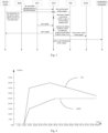
- the motor controller 2 stores the predetermined energy recovery torque curve.
- X-coordinate and Y-coordinate represent the current speed and the energy recovery torque respectively, and two curves are coasting energy recovery torque curves in the EHV mode and the HV mode of the vehicle.
- the coasting energy recovery torque curves at different road slope values are drawn by repeating test at different road slope values. As long as the current speed, the current road slope value and the working mode of the vehicle are known the corresponding coasting energy recovery torque value can be calculated according to the coasting energy recovery torque curve stored in the motor controller 2.
- Fig. 4 is the predetermined energy recovery torque curve at a certain road slope value (10°), and referring to Fig.
- the motor controller 2 calculates the second energy recovery torque value according to the current speed and the current working mode of the vehicle. By fully considering the influence of the current speed of the vehicle, the current road slope value and the current working mode of the vehicle on the coasting energy recovery, a more accurate second energy recovery torque value is obtained, thus enhancing the coasting energy recovery efficiency of the vehicle.
- the coasting energy recovery control system further includes a engine control module 12, and the engine control module 12 is configured to control an output torque of the engine 5 according to the target torque signal of the engine sent by the motor controller 2.
- the motor controller 2 sends the target torque signal of the engine to the engine control module 12, and then the engine control module 12 controls the output torque of the engine.
- the engine 5 does not provide the output torque while the vehicle is in the coasting energy recovery state, and thus the target torque signal of the engine sent by the motor controller 2 is equal to zero.
- the motor controller 2 does not send the target torque signal of the engine to the engine control module 12.
- the coasting energy recovery control system further includes the combination instrument 15, and the combination instrument 15 is configured to display power state information of the vehicle.
- the state information includes whether the vehicle is performing the coasting energy recovery in the EHV mode or in the HV mode.
- Embodiments of the present disclosure further provide a coasting energy recovery control method of the vehicle.
- the method includes: obtaining a current state of a power battery and obtaining a maximum charging power of the power battery according to the current state of the power battery; obtaining current states of a motor controller and an electric motor, and obtaining maximum energy recovery torque values of the motor controller and the electric motor respectively according to the current states of the motor controller and the electric motor; converting the maximum charging power of the power battery into a maximum energy recovery torque value of the power battery; comparing the maximum energy recovery torque value of the power battery, the maximum energy recovery torque value of the motor controller and the maximum energy recovery torque value of the electric motor to obtain a first minimum value and determining the first minimum value as a first energy recovery torque value; obtaining a second energy recovery torque value according to a current speed of the vehicle, a current road slope value, a current working mode of the vehicle and a predetermined energy recovery torque curve; comparing the first energy recovery torque value with the second energy recovery torque value to obtain a second minimum value, and
- the coasting energy recovery control method of the vehicle by calculating the maximum energy recovery torque value of the motor controller according to the current state of the motor controller, and comparing the maximum energy recovery torque value of the power battery, the maximum energy recovery torque value of the motor controller and the maximum energy recovery torque value of the electric motor to obtain the minimum value as the first energy recovery value, the impact of the current state of the motor controller on the coasting energy recovery of the vehicle is fully considered.
- the predetermined energy recovery torque curve in the motor controller and calculating the second energy recovery torque value according to the current speed of the vehicle, the current road slope value, the current working mode of the vehicle and the predetermined energy recovery torque curve, the impact of the current road condition and the working mode of the vehicle on the coasting energy recovery of the vehicle is also fully considered.
- the first energy recovery torque value with the second energy recovery torque value to obtain the minimum value as the final energy recovery torque value of the electric motor, the accuracy of the final energy recovery torque value of the electric motor is enhanced, thus improving the coasting energy recovery efficiency of the vehicle and keeping the comfort of the vehicle.
- the second energy recovery torque value is less than the first energy recovery torque value, and thus the second energy recovery torque value is generally used as the final energy recovery torque value of the electric motor.
- the second energy recovery torque value is calculated by fully considering the influence of the current speed, the current road condition and the working mode of the vehicle on the coasting energy recovery of the vehicle, and thus the second energy recovery torque value is more accurate, which can enhance the coasting energy recovery efficiency of the vehicle and keep the comfort of the vehicle.
- the current state of the power battery includes an electric quantity and a temperature of the power battery; the current state of the motor controller includes a temperature of the motor controller; the current state of the electric motor includes the temperature of the electric motor and the position of the motor rotor.
- the rated power and the current rotating speed of the electric motor are also obtained.
- the coasting energy recovery control method of the vehicle further includes: sampling the current speed of the vehicle; sampling a current accelerator pedal depth value; sampling a current gear signal of the vehicle; sampling the current road slope value and obtaining the current working mode of the vehicle, state information of an anti-lock braking system and state information of a cruise control system; and determining whether the vehicle is permitted to enter a coasting energy recovery state according to the current speed of the vehicle, the current accelerator pedal depth value, the current gear signal of the vehicle, the state information of the anti-lock braking system and the state information of the cruise control system by the motor controller.
- the battery manager calculates the maximum charging power of the power battery according to the current state of the power battery, and then the motor controller converts the maximum charging power of the power battery into the maximum energy recovery torque value of the power battery and sends the maximum energy recovery torque value of the power battery to a CAN bus.
- the shift control unit samples the current gear signal of the vehicle and sends the current gear signal of the vehicle to the CAN bus.
- the electronic speed controller samples the current speed of the vehicle, the state information of the anti-lock braking system and the state information of the cruise control system and sends the current speed of the vehicle, the state information of the anti-lock braking system and the state information of the cruise control system to the CAN bus.
- the vehicle is permitted to enter the coasting energy recovery state when the following conditions are satisfied: (1) the current speed of the vehicle is larger than or equal to a minimum vehicle speed threshold value; (2) the current accelerator pedal depth value is zero; (3) the anti-lock braking system is in a non-working state; (4) the cruise control system is in the non-working state; and (5) the current gear signal is a D gear signal.
- the coasting energy recovery control method of the vehicle further includes: determining whether the vehicle is permitted to exit the coasting energy recovery state according to the current speed of the vehicle, the current accelerator pedal depth value, the current gear signal of the vehicle, the state information of the anti-lock braking system and the state information of the cruise control system. Specifically, the vehicle is permitted to exit the coasting energy recovery state when one of the following conditions is satisfied: (1) the current speed of the vehicle is less than the minimum vehicle speed threshold; (2) the current accelerator pedal depth value is larger than zero; (3) the anti-lock braking system is in a working state; (4) the cruise control system is in the working state; and (5) the current gear signal is a non-D gear signal.
- the current road slope value is sampled by the motor controller.
- the motor controller further samples the current speed of the vehicle and the current working mode of the vehicle, and thus, by referring to the energy recovery torque curve stored in the motor controller, the motor controller can calculate the second energy recovery torque value according to the current speed of the vehicle, the current road slope value and the current working mode of the vehicle.
- the second energy recovery torque value is more accurate, which enhances the coasting energy recovery efficiency of the vehicle.
- the coasting energy recovery control method of the vehicle further includes: controlling an output torque of an engine according to a target torque signal of the engine sent from the motor controller.
- the motor controller sends the target torque signal of the engine to an engine control module, and then the engine control module controls the output torque of the engine.
- the engine does not provide the output torque while the vehicle is performing the coasting energy recovery, and thus the target torque signal of the engine equals to zero.
- the motor controller does not send the target torque signal of the engine to the engine control module.
- the motor controller obtains the maximum energy recovery torque values of the power battery, the motor controller and the electric motor.
- the battery manager obtains the current state of the power battery and calculates the maximum charging power of the power battery according to the current state of the power battery.
- the motor controller obtains the current state of the motor controller and calculates the maximum energy recovery torque value of the motor controller according to the current state of the motor controller.
- the motor controller converts the maximum charging power of the power battery into the maximum energy recovery torque value of the power battery.
- the motor controller obtains the current state of the electric motors and calculates the maximum energy recovery torque value of the electric motor according to the current state of the electric motor.
- the motor controller sets the first energy recovery-torque value. Specifically, the motor controller compares the maximum energy recovery torque value of the power battery, the maximum energy recovery torque value of the motor controller and the maximum energy recovery torque value of the electric motor to obtain a first minimum value, and then determines the first minimum value as the first energy recovery torque value.
- the electric motor controls the vehicle to perform the coasting energy recovery operation according to the final energy recovery torque value of the electric motor.
- the coasting energy recovery control method of the vehicle includes following steps.
- the battery manager calculates the maximum charging power of the power battery. Specifically, the battery manager obtains the current state of the power battery and calculates the maximum charging power of the power battery according to the current state of the power battery, in which the current state of the power battery includes the electric quantity and the temperature of the power battery, and then execute step S203.
- the motor controller calculates the first energy recovery torque value. Specifically, the motor controller compares the maximum energy recovery torque value of the power battery, the maximum energy recovery torque value of the motor controller and the maximum energy recovery torque value of the electric motor to obtain the first minimum value, and then determines the first minimum value as the first energy recovery torque value, then execute step S207.
- the motor controller calculates the second energy recovery torque value. Specifically, the motor controller stores the predetermined energy recovery torque curve, and the motor controller calculates the second energy recovery torque value according to the current speed of the vehicle, the current road slope value, the current working mode of the vehicle and the predetermined energy recovery torque curve, and then execute step S207.
- the motor controller sends the target torque signal to the engine control module, and then the engine control module controls the output torque of the engine according to the target torque signal of the engine.
- the output torque of the engine is used to provide the resistance to the vehicle, and thus, when the target torque signal of the engine is equal to zero, the engine control module controls the output torque of the engine to be zero.
- the engine is separated from the transmission device via a separator, thus controlling the engine to output a zero torque.
- the method for controlling the vehicle to enter the coasting energy recovery control state includes following steps.
- the throttle depth sensor samples the current accelerator pedal depth value, and determines whether the current accelerator pedal depth value is zero, if yes, execute step S303; and if no, execute step S307.
- step S306 the vehicle enters the coasting energy recovery control state.
- the method for controlling the vehicle to exit the coasting energy recovery control state includes following steps.
- the electronic speed controller samples the current speed of the vehicle and determines whether the current speed of the vehicle is less than the minimum vehicle speed threshold, if no, execute step S402; and if yes, execute step S407.
- the throttle depth sensor samples the current accelerator pedal depth value, and determines whether the current accelerator pedal depth value is larger than zero, if no, execute step S403; and if yes, execute step S407.
Landscapes
- Engineering & Computer Science (AREA)
- Transportation (AREA)
- Mechanical Engineering (AREA)
- Chemical & Material Sciences (AREA)
- Combustion & Propulsion (AREA)
- Power Engineering (AREA)
- Automation & Control Theory (AREA)
- Life Sciences & Earth Sciences (AREA)
- Sustainable Development (AREA)
- Sustainable Energy (AREA)
- Electric Propulsion And Braking For Vehicles (AREA)
- Hybrid Electric Vehicles (AREA)
Abstract
Description
- This application claims priority and benefits of
Chinese Patent Application No. 201310405003.9, filed with State Intellectual Property Office on September 9, 2013 - Embodiments of the present disclosure generally relate to a vehicle technology filed, and more particularly, to a vehicle, a coasting energy recovery (also sometimes translated as "sliding feedback") control system of the vehicle and a coasting energy recovery control method of the vehicle.
- An electric vehicle uses a power battery as a power source. A problem of the electric vehicle is how to improve a driving energy efficiency of the electric vehicle so as to extend a driving distance of the electric vehicle. An energy recovery is one effective measure to solve the above problem.
- The energy recovery includes braking energy recovery and coasting energy recovery. During a coasting energy recovery of the electric vehicle, a motor controller controls an electric motor to energy recovery according to a calculated energy recovery torque, so as to charge the power battery, to increase the driving distance of the electric vehicle, and to reduce the pollutant emission and the wear caused by the mechanical brake.
- Now, a coasting energy recovery control system and method of a vehicle has already been provided. The method includes: calculating an initial energy recovery torque value of the electric motor according to a current speed of the vehicle and a calibrated coasting deceleration; calculating a constraint energy recovery torque value of the power battery according to a temperature and a SOC (State of Charge) of the power battery; calculating a constraint energy recovery torque value of the electric motor according to a rotating speed of the electric motor; determining a final energy recovery torque value of the electric motor as a minimum of the initial energy recovery torque value of the electric motor, the constraint energy recovery torque value of the power battery and the constraint energy recovery torque value of the electric motor; and controlling the vehicle to recovery the coasting energy according to the final energy recovery torque value of the electric motor.
- Although the above method can calculate the final energy recovery torque value of the electric motor to improve the efficiency of recovering the coasting energy of the vehicle, there are still some problems: a constraint energy recovery torque value of the motor controller is not calculated in the above method, and thus an influence of a current state of the motor controller on the energy recovery torque value of the electric motor is not fully considered, in which the current state of the motor controller influences an output power of the electric motor directly and thus influences the energy recovery torque value of the electric motor; in addition, the above method does not fully consider the influence of the current road condition and the working mode of the vehicle on the coasting energy recovery of the vehicle. Thus, the final energy recovery torque value of the electric motor calculated by the above method is not perfect, which may influence the coasting energy recovery efficiency of the vehicle.
- Embodiments of the present disclosure seek to solve at least one of the problems existing in the related art to at least some extent.
- A first object of the present disclosure is to provide a coasting energy recovery control system of a vehicle, which can fully consider an influence of a current state of the motor controller, a current road condition and a working mode of the vehicle on the coasting energy recovery, thus enhancing an accuracy of calculating a final energy recovery torque value of an electric motor, improving an coasting energy recovery efficiency of the vehicle and keeping a comfort of the vehicle.
- A second object of the present disclosure is to provide a vehicle.
- A third object of the present disclosure is to provide a coasting energy recovery control method of the vehicle.
- In order to achieve above objects, embodiments of a first aspect of the present disclosure provide a coasting energy recovery control system of the vehicle, including: an electric motor; a power battery configured to supply power to the electric motor; a battery manager connected with the power battery, and configured to obtain a current state of the power battery, and to obtain a maximum charging power of the power battery according to the current state of the power battery; and a motor controller connected with the electric motor, and configured to obtain current states of the motor controller and the electric motor, to obtain maximum energy recovery torque values of the motor controller and the electric motor respectively according to the current states of the motor controller and the electric motor, to convert the max charging power of the power battery into a maximum energy recovery torque value of the power battery, to determine a minimum of the maximum energy recovery torque value of the power battery, the maximum energy recovery torque value of the motor controller and the maximum energy recovery torque value of the electric motor as a first energy recovery torque value, to obtain a second energy recovery torque value according to a current speed of the vehicle, a current road slope value, a current working mode of the vehicle and a predetermined energy recovery torque curve, and to determine a minimum of the first energy recovery torque value and the second energy recovery torque value as a final energy recovery torque value of the electric motor, such that the electric motor controls the vehicle to perform a coasting energy recovery operation according to the final energy recovery torque value.
- With the coasting energy recovery control system of the vehicle according to embodiments of the present disclosure, by calculating the maximum energy recovery torque value of the motor controller according to the current state of the motor controller, and comparing the maximum energy recovery torque value of the power battery, the maximum energy recovery torque value of the motor controller and the maximum energy recovery torque value of the electric motor to obtain the minimum value as the first energy recovery value, the impact of the current state of the motor controller on the coasting energy recovery of the vehicle is fully considered. In addition, by storing the predetermined energy recovery torque curve in the motor controller and calculating the second energy recovery torque value according to the current speed of the vehicle, the current road slope value, the current working mode of the vehicle and the predetermined energy recovery torque curve, the impact of the current road condition and the working mode of the vehicle on the coasting energy recovery of the vehicle is also fully considered. Finally, by comparing the first energy recovery torque value with the second energy recovery torque value to obtain the minimum value as the final energy recovery torque value of the electric motor, the accuracy of the final energy recovery torque value of the electric motor is enhanced, thus improving the coasting energy recovery efficiency of the vehicle and keeping the comfort of the vehicle.
- In order to achieve the above objects, embodiments of a second aspect of the present disclosure provide a vehicle, including the above coasting energy recovery control system.
- With the vehicle according to embodiments of the present disclosure, by calculating the maximum energy recovery torque value of the motor controller according to the current state of the motor controller, and comparing the maximum energy recovery torque value of the power battery, the maximum energy recovery torque value of the motor controller and the maximum energy recovery torque value of the electric motor to obtain the minimum value as the first energy recovery value, the impact of the current state of the motor controller on the coasting energy recovery of the vehicle is fully considered. In addition, by storing the predetermined energy recovery torque curve in the motor controller and calculating the second energy recovery torque value according to the current speed of the vehicle, the current road slope value, the current working mode of the vehicle and the predetermined energy recovery torque curve, the impact of the current road condition and the working mode of the vehicle on the coasting energy recovery of the vehicle is also fully considered. Finally, by comparing the first energy recovery torque value with the second energy recovery torque value to obtain the minimum value as the final energy recovery torque value of the electric motor, the accuracy of the final energy recovery torque value of the electric motor is enhanced, thus improving the coasting energy recovery efficiency of the vehicle and keeping the comfort of the vehicle.
- In order to achieve the above objects, embodiments of a third aspect of the present disclosure provide a coasting energy recovery control method of the vehicle, including: obtaining a current state of a power battery and obtaining a maximum charging power of the power battery according to the current state of the power battery; obtaining current states of a motor controller and an electric motor, and obtaining maximum energy recovery torque values of the motor controller and the electric motor respectively according to the current states of the motor controller and the electric motor; converting the maximum charging power of the power battery into a maximum energy recovery torque value of the power battery; comparing the maximum energy recovery torque value of the power battery, the maximum energy recovery torque value of the motor controller and the maximum energy recovery torque value of the electric motor to obtain a first minimum value, and determining the first minimum value as a first energy recovery torque value; obtaining a second energy recovery torque value according to a current speed of the vehicle, a current road slope value, a current working mode of the vehicle and a predetermined energy recovery torque curve; comparing the first energy recovery torque value with the second energy recovery torque value to obtain a second minimum value, and determining the second minimum value as a final energy recovery torque value of the electric motor; and controlling the vehicle to perform a coasting energy recovery operation according to the final energy recovery torque value of the electric motor.
- With the method for the coasting energy recovery control system of the vehicle according to embodiments of the present disclosure, by calculating the maximum energy recovery torque value of the motor controller according to the current state of the motor controller, and comparing the maximum energy recovery torque value of the power battery, the maximum energy recovery torque value of the motor controller and the maximum energy recovery torque value of the electric motor to obtain the minimum value as the first energy recovery value, the impact of the current state of the motor controller on the coasting energy recovery of the vehicle is fully considered. In addition, by storing the predetermined energy recovery torque curve in the motor controller and calculating the second energy recovery torque value according to the current speed of the vehicle, the current road slope value, the current working mode of the vehicle and the predetermined energy recovery torque curve, the impact of the current road condition and the working mode of the vehicle on the coasting energy recovery of the vehicle is also fully considered. Finally, by comparing the first energy recovery torque value with the second energy recovery torque value to obtain the minimum value as the final energy recovery torque value of the electric motor, the accuracy of the final energy recovery torque value of the electric motor is enhanced, thus improving the coasting energy recovery efficiency of the vehicle and keeping the comfort of the vehicle.
- Additional aspects and advantages of embodiments of present disclosure will be given in part in the following descriptions, become apparent in part from the following descriptions, or be learned from the practice of the embodiments of the present disclosure.
- These and other aspects and advantages of embodiments of the present disclosure will become apparent and more readily appreciated from the following descriptions made with reference to the accompanying drawings, in which:
-
Fig. 1 is a schematic diagram of a vehicle according to an embodiment of the present disclosure; -
Fig. 2 is a schematic diagram of a coasting energy recovery control system of a vehicle according to an embodiment of the present disclosure; -
Fig. 3 is a schematic diagram showing a signal flow of a coasting energy recovery control system of a vehicle according to an embodiment of the present disclosure; -
Fig. 4 is a schematic diagram showing a relationship between a speed of a vehicle and a energy recovery torque of a vehicle according to an embodiment of the present disclosure; -
Fig. 5 is a flow chart of a coasting energy recovery control method of a vehicle according to an embodiment of the present disclosure; -
Fig. 6 is a flow chart of a coasting energy recovery control method of a vehicle according to another embodiment of the present disclosure; -
Fig. 7 is a flow chart of a method of controlling a vehicle to enter a coasting energy recovery control state according to an embodiment of the present disclosure; and -
Fig. 8 is a flow chart of a method of controlling a vehicle to exit a coasting energy recovery control state according to an embodiment of the present disclosure. - Reference will be made in detail to embodiments of the present disclosure. Embodiments of the present disclosure will be shown in drawings, in which the same or similar elements and the elements having same or similar functions are denoted by like reference numerals throughout the descriptions. The embodiments described herein according to drawings are explanatory and illustrative, not construed to limit the present disclosure.
- The following description provides a plurality of embodiments or examples configured to achieve different structures of the present disclosure. In order to simplify the publishment of the present disclosure, components and dispositions of the particular embodiment are described in the following, which are only explanatory and not construed to limit the present disclosure. In addition, the present disclosure may repeat the reference number and/or letter in different embodiments for the purpose of simplicity and clarity, and the repeat does not indicate the relationship of the plurality of embodiments and/or dispositions. Moreover, in description of the embodiments, the structure of the second characteristic "above" the first characteristic may include an embodiment formed by the first and second characteristic contacted directly, and also may include another embodiment formed between the first and the second characteristic, in which the first characteristic and the second characteristic may not contact directly.
- In the description of the present disclosure, unless specified or limited otherwise, it should be noted that, terms "mounted," "connected" and "coupled" may be understood broadly, such as electronic connection or mechanical connection, inner communication between two elements, direct connection or indirect connection via intermediary. These having ordinary skills in the art should understand the specific meanings in the present disclosure according to specific situations.
- With reference to the following descriptions and drawings, these and other aspects of embodiments of the present disclosure will be distinct. In the descriptions and drawings, some particular embodiments are described in order to show means of the principles of embodiments according to the present disclosure, however, it should be appreciated that the scope of embodiments according to the present disclosure is not limited. On the contrary, embodiments of the present disclosure include all the changes, alternatives, and modifications falling into the scope of the spirit and principles of the attached claims.
- In the following, a vehicle, a coasting energy recovery (also sometimes referred to as "sliding feedback") control system of the vehicle and a coasting energy recovery control method of the vehicle are described in detail with reference to drawings.
-
Fig. 1 is a schematic diagram of the vehicle according to an embodiment of the present disclosure. As shown inFig. 1 , the vehicle includes the coasting energyrecovery control system 101, atransmission device 7,wheels gear reducer 4, adouble clutch gearbox 6 and anengine 5. Theengine 5 is connected with thetransmission device 7 via thedouble clutch gearbox 6, thetransmission device 7 is configured to drive thewheels recovery control system 101 is connected with thetransmission device 7 via thegear reducer 4. -
Fig. 2 is a schematic diagram of the coasting energy recovery control system of the vehicle according to an embodiment of the present disclosure.Fig. 3 is a schematic diagram showing a signal flow of the coasting energy recovery control system of the vehicle according to an embodiment of the present disclosure. As shown inFig. 2 , the coasting energyrecovery control system 101 of the vehicle includes apower battery 1, a battery manager 9, an electric motor 3 and amotor controller 2. Thepower battery 1 is used as a power storage unit. Themotor controller 2 is connected with thepower battery 1 via a DC bus, and connected with the electric motor 3 via an AC three-phase wire. The electric motor 3 is connected with thetransmission device 7 via thegear reducer 4 and outputs a energy recovery torque to thetransmission device 7 via thegear reducer 4, such that thetransmission device 7 transfers the energy recovery torque of the electric motor 3 to thewheels - In an embodiment of the present disclosure, the coasting energy recovery control of the vehicle refers to the coasting energy recovery control performed when an accelerator pedal of the vehicle is completely released. When the vehicle enters the coasting energy recovery state, the accelerator pedal of the vehicle is completely released, such that, on one hand, the electric motor 3 provides a resistance to the
wheels wheels transmission device 7 and then sent to the electric motor 3 via thetransmission device 7 and thegear reducer 4, the electric motor 3 starts the generating function to convert the mechanical energy into an electric energy and sends the electric energy to themotor controller 2, themotor controller 2 rectifies a three-phase AC into a suitable DC to charge thepower battery 1. - In an embodiment of the present disclosure, the coasting energy
recovery control system 101 is connected with the doubleclutch gearbox 6 via theengine 5. When the vehicle enters the coasting energy recovery state, the accelerator pedal of the vehicle is completely released, the vehicle tends to slow down, and the energy is sent from thewheels transmission device 7 and then sent to theengine 5 via thetransmission device 7 and the doubleclutch gearbox 6. At this time, the vehicle does not provide fuel to theengine 5, and the energy transferred to theengine 5 from thewheels engine 5. - In an embodiment of the present disclosure, the battery manager 9 is connected with the
power battery 1, and configured to obtain a current state of thepower battery 1, and to obtain a maximum charging power of thepower battery 1 according to the current state of thepower battery 1. Themotor controller 2 is configured to obtain current states of the motor controller and the electric motor, to obtain maximum energy recovery torque values of the motor controller and the electric motor respectively according to the current states of the motor controller and the electric motor, to convert the maximum charging power of the power battery into a maximum energy recovery torque value of the power battery, to determine a minimum of the maximum energy recovery torque value of the power battery, the maximum energy recovery torque value of the motor controller and the maximum energy recovery torque value of the electric motor as a first energy recovery torque value. Themotor controller 2 is also configured to obtain a second energy recovery torque value according to a current speed of the vehicle, a current road slope value, a current working mode of the vehicle and a predetermined energy recovery torque curve, to compare the first energy recovery torque value with the second energy recovery torque value to determine a minimum of them as a final energy recovery torque value of the electric motor 3. The electric motor 3 is configured to control the vehicle to perform a coasting energy recovery operation according to the final energy recovery torque value. - With the coasting energy recovery control system of the vehicle according to embodiments of the present disclosure, by calculating the maximum energy recovery torque value of the motor controller according to the current state of the motor controller, and comparing the maximum energy recovery torque value of the power battery, the maximum energy recovery torque value of the motor controller and the maximum energy recovery torque value of the electric motor to obtain the minimum value as the first energy recovery value, the impact of the current state of the motor controller on the coasting energy recovery of the vehicle is fully considered. In addition, by storing the predetermined energy recovery torque curve in the motor controller and calculating the second energy recovery torque value according to the current speed of the vehicle, the current road slope value, the current working mode of the vehicle and the predetermined energy recovery torque curve, the impact of the current road condition and the working mode of the vehicle on the coasting energy recovery of the vehicle is also fully considered. Finally, by comparing the first energy recovery torque value with the second energy recovery torque value to obtain the minimum value as the final energy recovery torque value of the electric motor, the accuracy of the final energy recovery torque value of the electric motor is enhanced, thus improving the coasting energy recovery efficiency of the vehicle and keeping the comfort of the vehicle.
- In an embodiment of the present disclosure, the current state of the
power battery 1 obtained by the battery manager 9 includes an electric quantity and a temperature of the power battery. The current electric quantity of the power battery directly influences the maximum charging power of the power battery. Generally, the current electric quantity of the power battery is inversely proportional to the maximum charging power of the power battery. The temperature of the power battery influences an internal performance of the power battery, and when the temperature of the power battery is too high or too low, an abnormal situation will be caused in thepower battery 1, thus affecting the maximum charging power of the power battery. - In an embodiment of the present disclosure, the current state of the motor controller includes the temperature of the motor controller. The
motor controller 2 is configured to drive the electric motor 3, and the current state of the motor controller directly affects the output power of the electric motor and also affects the energy recovery torque of the electric motor, and thus the maximum energy recovery torque value of the motor controller is calculated in the present disclosure. The temperature of the motor controller directly affects the maximum energy recovery torque value of the motor controller. Generally, the temperature of the motor controller is inversely proportional to the maximum energy recovery torque value of the motor controller. When the temperature of the motor controller is high, the maximum energy recovery torque value of the motor controller is low. At this time, if the electric motor 3 performs the coasting energy recovery operation according to the larger maximum energy recovery torque value of the motor controller, a current in a main circuit of themotor controller 2 is caused to be higher to generate greater heat, which seriously affects the performance of themotor controller 2 and even causes a failure of themotor controller 2. - In an embodiment of the present disclosure, the current state of the electric motor obtained by the
motor controller 2 includes the temperature of the electric motor and a position of a motor rotor. The temperature of the electric motor directly affects the maximum energy recovery torque value of the electric motor. Generally, the temperature of the electric motor is inversely proportional to the maximum energy recovery torque value of the electric motor. If the temperature of the electric motor is high and the electric motor 3 performs the coasting energy recovery operation according to a larger maximum energy recovery torque value of the electric motor, the temperature of the electric motor will rise sharply, which seriously affects the performance of the electric motor 3 and even causes a failure of the electric motor 3. In addition, the electric motor 3 drives the vehicle to perform the coasting energy recovery operation according to the position of the motor rotor. In another embodiment of the present disclosure, themotor controller 2 further obtains a rated power and a current rotating speed of the electric motor, in which the rated power of the electric motor affects the maximum energy recovery torque value of the vehicle, and the current rotating speed of the electric motor directly affects the current energy recovery torque value of the vehicle. - In an embodiment of the present disclosure, the coasting energy
recovery control system 101 of the vehicle further includes: anelectronic speed controller 11, configured to sample the current speed of the vehicle; athrottle depth sensor 13, configured to sample a current accelerator pedal depth value; ashift control unit 10, configured to sample a current gear signal of the vehicle; and atemperature sensor 14, connected with thepower battery 1, the electric motor 3 and themotor controller 2 respectively, and configured to sample temperature values of thepower battery 1, the electric motor 3 and themotor controller 2. Themotor controller 2 is connected with theelectronic speed controller 11, thethrottle depth sensor 13 and theshift control unit 10 respectively. After the battery manager 9 obtains the current state of thepower battery 1, the battery manager 9 calculates the maximum charging power of thepower battery 1 according to the current state of the power battery, and then themotor controller 2 converts the maximum charging power of the power battery into the maximum energy recovery torque value of the power battery and sends the maximum energy recovery torque value of the power battery to a CAN bus. Theshift control unit 10 sends the current gear signal of the vehicle to the CAN bus. Theelectronic speed controller 11 sends the current speed of the vehicle, state information of the anti-lock braking system and state information of the cruise control system to the CAN bus. Thethrottle depth sensor 13 sends the current accelerator pedal depth value to the CAN bus. The electric motor 3 samples the position of the motor rotor via sensors, and sends the position signal to themotor controller 2. Themotor controller 2 obtains the current working mode of the vehicle, the state information of the anti-lock braking system, the state information of a cruise control system, and the signals sent by theelectronic speed controller 1 1, theshift control unit 10, thethrottle depth sensor 13 and thetemperature sensor 14 via the CAN bus, and themotor controller 2 determines whether the vehicle is permitted to enter a coasting energy recovery state or to exit the coasting energy recovery state according to the above signals and information. - In an embodiment of the present disclosure, the
motor controller 2 permits the vehicle to enter the coasting energy recovery state when the following conditions are satisfied: (1) the current speed of the vehicle sampled by theelectronic speed controller 11 is larger than or equal to a minimum vehicle speed threshold, this is because, if the vehicle enters the coasting energy recovery state when the current speed of the vehicle is less than the minimum vehicle speed threshold an obvious braking impact will be caused (which affects the comfort of the vehicle), and moreover, the energy from the coasting energy recovery is less due to the low speed of the vehicle (which makes the coasting energy recovery state of the vehicle not necessary). Generally, the minimum vehicle speed threshold is 13km/h; (2) the current accelerator pedal depth value sampled by the throttle depth sensor is zero, this is because, the coasting energy recovery control of the vehicle in the present disclosure refers to the coasting energy recovery control performed when the accelerator pedal of the vehicle is completely released, and thus when the current accelerator pedal depth value sampled by the throttle depth sensor is zero, the vehicle is permitted to enter the coasting energy recovery state; (3) the anti-lock braking system is in a non-working state, this is because, when the anti-lock braking system works, it controls the vehicle to maintain a stable braking force, and if the vehicle enters the coasting energy recovery state at this time, it is difficult for the vehicle to maintain the stable braking force, which goes against the overall control of the vehicle; (4) the cruise control system is in the non-working state, this is because, when the cruise control system is working, the vehicle will maintain a predetermined speed, which is in conflict with the object of the coasting energy recovery of the vehicle (i.e. slowing down the vehicle); (5) the current gear signal sampled by the shift control unit is a D gear signal, this is because, the coasting energy recovery control of the vehicle in the present disclosure refers to a D-gear coasting energy recovery control performed when the accelerator pedal of the vehicle is completely released, and if the vehicle is performing the coasting energy recovery in N gear, a driving intention of a driver is generally considered as coasting a short distance in N gear, and the coasting energy recovery control is not needed. - In an embodiment of the present disclosure, the
motor controller 2 is further configured to determine whether the vehicle is permitted to exit the coasting energy recovery state according to the current speed of the vehicle, the current accelerator pedal depth value, the current gear signal of the vehicle, the state information of the anti-lock braking system and the state information of the cruise control system. Specifically, the vehicle is permitted to exit the coasting energy recovery state when one of the following conditions is satisfied: (1) the current speed of the vehicle sampled by the electronic speed controller is less than the minimum vehicle speed threshold; (2) the current accelerator pedal depth value sampled by the throttle depth sensor is larger than zero; (3) the anti-lock braking system is in a working state; (4) the cruise control system is in the working state; (5) the current gear signal sampled by the shift control unit is a non-D gear signal. - The current working mode of the vehicle has a direct influence on the coasting energy recovery control, and specifically, an EV (Electric Vehicle) mode and a HEV (Hybrid Electric Vehicle) mode of the vehicle directly affects the coasting energy recovery control. When the vehicle performs the coasting energy recovery in the HEV mode, the
engine 5 provides a resistance force to the vehicle, and when the vehicle performs the coasting energy recovery in the EV mode, theengine 5 does not provide the resistance force to the vehicle. Thus, the coasting energy recovery control methods in different modes are different. - As shown in
Fig. 3 , the shift control unit (SCU) is configured to sample a gear signal and to transmit the gear signal to the motor controller (ECN). The battery manager sends the maximum charging power of the power battery to the motor controller (ECN).The electric motor sends the temperature of the electric motor and the position of the motor rotor to the motor controller (ECN). The electronic speed controller (ESC) sends the current speed of the vehicle to the motor controller (ECN).The motor controller (ECN) determines whether to permit the vehicle to enter or exit the coasting energy recovery state according to the current speed of the vehicle, the current accelerator pedal depth value, the current gear signal of the vehicle, the state information of the anti-lock braking system and the state information of the cruise control system, controls the coasting energy recovery according the predetermined coasting energy recovery torque curve, and sends a drive signal to the electric motor 3 and sends a target torque signal of the engine to the engine control module (ECM). Thecombination instrument 15 is configured to display power state information of the vehicle. - In different speeds, the coasting energy recovery torque of the vehicle is different. When the speed of the vehicle is higher, the resistance of the vehicle is larger, and the coasting energy recovery torque is lower. At this time, if the coasting energy recovery torque is larger, the vehicle has the obvious braking impact, which affects the comfort of the vehicle. When the speed of the vehicle is moderate, the coasting energy recovery torque is larger due to economy of the operation region of the power system and the resistance of the vehicle. When the speed of the vehicle is lower, in order to keep the comfort of the vehicle, the coasting energy recovery torque is lower.
- The road slope value also directly affects the coasting energy recovery control of the vehicle. During the vehicle drives downhill, when the current road slope value is larger than the maximum road slope value, the vehicle generally enters the braking state, at this time the vehicle enters the braking energy recovery control according to the intention of the driver. When the current road slope value is less than the maximum road slope value, if the vehicle slides in a constant speed, the coasting energy recovery torque value is larger, if the vehicle slides in a lower acceleration, the coasting energy recovery torque value is lower. Therefore, during the vehicle drives downhill, by calculating the coasting energy recovery torque value according to the current speed of the vehicle and the current road slope value, the coasting energy recovery efficiency of the vehicle is enhanced at the extreme and the comfort of the vehicle is kept.
- In an embodiment of the present disclosure, the
motor controller 2 stores the predetermined energy recovery torque curve. As shown inFig. 4 , X-coordinate and Y-coordinate represent the current speed and the energy recovery torque respectively, and two curves are coasting energy recovery torque curves in the EHV mode and the HV mode of the vehicle. The coasting energy recovery torque curves at different road slope values are drawn by repeating test at different road slope values. As long as the current speed, the current road slope value and the working mode of the vehicle are known the corresponding coasting energy recovery torque value can be calculated according to the coasting energy recovery torque curve stored in themotor controller 2.Fig. 4 is the predetermined energy recovery torque curve at a certain road slope value (10°), and referring toFig. 4 , themotor controller 2 calculates the second energy recovery torque value according to the current speed and the current working mode of the vehicle. By fully considering the influence of the current speed of the vehicle, the current road slope value and the current working mode of the vehicle on the coasting energy recovery, a more accurate second energy recovery torque value is obtained, thus enhancing the coasting energy recovery efficiency of the vehicle. - In an embodiment of the present disclosure, the coasting energy recovery control system further includes a
engine control module 12, and theengine control module 12 is configured to control an output torque of theengine 5 according to the target torque signal of the engine sent by the motor controller 2.When the vehicle is performing the coasting energy recovery in the HEV mode, themotor controller 2 sends the target torque signal of the engine to theengine control module 12, and then theengine control module 12 controls the output torque of the engine. In embodiments of the present disclosure, considering the intention of the driver and the economical efficiency, theengine 5 does not provide the output torque while the vehicle is in the coasting energy recovery state, and thus the target torque signal of the engine sent by themotor controller 2 is equal to zero. When the vehicle is in the EHV mode, theengine 5 does not work, and thus themotor controller 2 does not send the target torque signal of the engine to theengine control module 12. - In an embodiment of the present disclosure, the coasting energy recovery control system further includes the
combination instrument 15, and thecombination instrument 15 is configured to display power state information of the vehicle. The state information includes whether the vehicle is performing the coasting energy recovery in the EHV mode or in the HV mode. - Embodiments of the present disclosure further provide a coasting energy recovery control method of the vehicle. The method includes: obtaining a current state of a power battery and obtaining a maximum charging power of the power battery according to the current state of the power battery; obtaining current states of a motor controller and an electric motor, and obtaining maximum energy recovery torque values of the motor controller and the electric motor respectively according to the current states of the motor controller and the electric motor; converting the maximum charging power of the power battery into a maximum energy recovery torque value of the power battery; comparing the maximum energy recovery torque value of the power battery, the maximum energy recovery torque value of the motor controller and the maximum energy recovery torque value of the electric motor to obtain a first minimum value and determining the first minimum value as a first energy recovery torque value; obtaining a second energy recovery torque value according to a current speed of the vehicle, a current road slope value, a current working mode of the vehicle and a predetermined energy recovery torque curve; comparing the first energy recovery torque value with the second energy recovery torque value to obtain a second minimum value, and determining the second minimum value as a final energy recovery torque value of the electric motor; and controlling the vehicle to perform a coasting energy recovery operation according to the final energy recovery torque value of the electric motor.
- With the coasting energy recovery control method of the vehicle according to embodiments of the present disclosure, by calculating the maximum energy recovery torque value of the motor controller according to the current state of the motor controller, and comparing the maximum energy recovery torque value of the power battery, the maximum energy recovery torque value of the motor controller and the maximum energy recovery torque value of the electric motor to obtain the minimum value as the first energy recovery value, the impact of the current state of the motor controller on the coasting energy recovery of the vehicle is fully considered. In addition, by storing the predetermined energy recovery torque curve in the motor controller and calculating the second energy recovery torque value according to the current speed of the vehicle, the current road slope value, the current working mode of the vehicle and the predetermined energy recovery torque curve, the impact of the current road condition and the working mode of the vehicle on the coasting energy recovery of the vehicle is also fully considered. Finally, by comparing the first energy recovery torque value with the second energy recovery torque value to obtain the minimum value as the final energy recovery torque value of the electric motor, the accuracy of the final energy recovery torque value of the electric motor is enhanced, thus improving the coasting energy recovery efficiency of the vehicle and keeping the comfort of the vehicle.
- Specifically, when the vehicle is in the normally coasting energy recovery state, the second energy recovery torque value is less than the first energy recovery torque value, and thus the second energy recovery torque value is generally used as the final energy recovery torque value of the electric motor. The second energy recovery torque value is calculated by fully considering the influence of the current speed, the current road condition and the working mode of the vehicle on the coasting energy recovery of the vehicle, and thus the second energy recovery torque value is more accurate, which can enhance the coasting energy recovery efficiency of the vehicle and keep the comfort of the vehicle. When the power battery, the motor controller or the electric motor has a fault, in order to give consideration to the working performance of the electric motor, the motor controller and the power battery and to achieve the coasting energy recovery of the vehicle, the first energy recovery torque value is used as the final energy recovery torque value of the electric motor, which effectively ensures the coasting energy recovery efficiency of the vehicle and keep the comfort of the vehicle.
- In an embodiment of the present disclosure, the current state of the power battery includes an electric quantity and a temperature of the power battery; the current state of the motor controller includes a temperature of the motor controller; the current state of the electric motor includes the temperature of the electric motor and the position of the motor rotor. In another embodiment of the present disclosure, the rated power and the current rotating speed of the electric motor are also obtained.
- In an embodiment of the present disclosure, the coasting energy recovery control method of the vehicle further includes: sampling the current speed of the vehicle; sampling a current accelerator pedal depth value; sampling a current gear signal of the vehicle; sampling the current road slope value and obtaining the current working mode of the vehicle, state information of an anti-lock braking system and state information of a cruise control system; and determining whether the vehicle is permitted to enter a coasting energy recovery state according to the current speed of the vehicle, the current accelerator pedal depth value, the current gear signal of the vehicle, the state information of the anti-lock braking system and the state information of the cruise control system by the motor controller. Specifically, after the battery manager obtains the current state of the power battery, the battery manager calculates the maximum charging power of the power battery according to the current state of the power battery, and then the motor controller converts the maximum charging power of the power battery into the maximum energy recovery torque value of the power battery and sends the maximum energy recovery torque value of the power battery to a CAN bus. The shift control unit samples the current gear signal of the vehicle and sends the current gear signal of the vehicle to the CAN bus. The electronic speed controller samples the current speed of the vehicle, the state information of the anti-lock braking system and the state information of the cruise control system and sends the current speed of the vehicle, the state information of the anti-lock braking system and the state information of the cruise control system to the CAN bus. The throttle depth sensor samples the current accelerator pedal depth value and sends the current accelerator pedal depth signal to the CAN bus. The electric motor samples the position of a motor rotor, and sends the position of the motor rotor to the motor controller. The motor controller obtains the signals sent by the electronic speed controller, the shift control unit, the throttle depth sensor and the temperature sensor via the CAN bus, and determines whether the vehicle is permitted to enter a coasting energy recovery state or to exit the coasting energy recovery state according to the above signals.
- In an embodiment of the present disclosure, the vehicle is permitted to enter the coasting energy recovery state when the following conditions are satisfied: (1) the current speed of the vehicle is larger than or equal to a minimum vehicle speed threshold value; (2) the current accelerator pedal depth value is zero; (3) the anti-lock braking system is in a non-working state; (4) the cruise control system is in the non-working state; and (5) the current gear signal is a D gear signal.
- In an embodiment of the present disclosure, the coasting energy recovery control method of the vehicle further includes: determining whether the vehicle is permitted to exit the coasting energy recovery state according to the current speed of the vehicle, the current accelerator pedal depth value, the current gear signal of the vehicle, the state information of the anti-lock braking system and the state information of the cruise control system. Specifically, the vehicle is permitted to exit the coasting energy recovery state when one of the following conditions is satisfied: (1) the current speed of the vehicle is less than the minimum vehicle speed threshold; (2) the current accelerator pedal depth value is larger than zero; (3) the anti-lock braking system is in a working state; (4) the cruise control system is in the working state; and (5) the current gear signal is a non-D gear signal.
- In an embodiment of the present disclosure, the current road slope value is sampled by the motor controller. The motor controller further samples the current speed of the vehicle and the current working mode of the vehicle, and thus, by referring to the energy recovery torque curve stored in the motor controller, the motor controller can calculate the second energy recovery torque value according to the current speed of the vehicle, the current road slope value and the current working mode of the vehicle. By fully considering the influence of the current speed of the vehicle, the current road slope value and the current working mode of the vehicle on the coasting energy recovery, the second energy recovery torque value is more accurate, which enhances the coasting energy recovery efficiency of the vehicle.
- In an embodiment of the present disclosure, the coasting energy recovery control method of the vehicle further includes: controlling an output torque of an engine according to a target torque signal of the engine sent from the motor controller. When the vehicle is performing the coasting energy recovery in the HEV mode, the motor controller sends the target torque signal of the engine to an engine control module, and then the engine control module controls the output torque of the engine. Considering the intention of the driver and the economical efficiency, the engine does not provide the output torque while the vehicle is performing the coasting energy recovery, and thus the target torque signal of the engine equals to zero. When the vehicle is in the EV mode, the engine does not work, and thus the motor controller does not send the target torque signal of the engine to the engine control module.
- In an embodiment of the present disclosure, the coasting energy recovery control method of the vehicle further includes: displaying power state information of the vehicle on a combination instrument. The state information includes whether the coasting energy recovery of the vehicle is in the EHV mode or in the HV mode.
-
Fig. 5 is a flow chart of a coasting energy recovery control method of a vehicle according to an embodiment of the present disclosure. As shown inFig. 5 , the method includes following steps. - At step S101, the motor controller determines that the vehicle is permitted to enter the coasting energy recovery state.
- At step S 102, the motor controller obtains the maximum energy recovery torque values of the power battery, the motor controller and the electric motor. Specifically, the battery manager obtains the current state of the power battery and calculates the maximum charging power of the power battery according to the current state of the power battery. The motor controller obtains the current state of the motor controller and calculates the maximum energy recovery torque value of the motor controller according to the current state of the motor controller. The motor controller converts the maximum charging power of the power battery into the maximum energy recovery torque value of the power battery. The motor controller obtains the current state of the electric motors and calculates the maximum energy recovery torque value of the electric motor according to the current state of the electric motor.
- At step S103, the motor controller sets the first energy recovery-torque value. Specifically, the motor controller compares the maximum energy recovery torque value of the power battery, the maximum energy recovery torque value of the motor controller and the maximum energy recovery torque value of the electric motor to obtain a first minimum value, and then determines the first minimum value as the first energy recovery torque value.
- At
step S 104, the motor controller calculates the second energy recovery-torque value. Specifically, the motor controller stores the predetermined energy recovery torque curve, and the motor controller calculates the second energy recovery torque value according to the current speed of the vehicle, the current road slope value, the current working mode of the vehicle and the predetermined energy recovery torque curve. - At step S105, the motor controller compares the first energy recovery torque value with the second energy recovery torque value to determine the minimum of them as the final energy recovery torque value of the electric motor.
- At step S 106, the electric motor controls the vehicle to perform the coasting energy recovery operation according to the final energy recovery torque value of the electric motor.
- In another embodiment of the present disclosure, as shown in
Fig. 6 , the coasting energy recovery control method of the vehicle includes following steps. - At step S201, the motor controller determines whether the vehicle is permitted to enter the coasting energy recovery state, if yes, execute step S202, step S203 and step S204 at the same time; and if no, execute step S211.
- At step S202, the battery manager calculates the maximum charging power of the power battery. Specifically, the battery manager obtains the current state of the power battery and calculates the maximum charging power of the power battery according to the current state of the power battery, in which the current state of the power battery includes the electric quantity and the temperature of the power battery, and then execute step S203.
- At step S203, the motor controller calculates the maximum energy recovery torque value of the motor controller and converts the maximum charging power of the power battery into the maximum energy recovery torque value of the power battery. Specifically, the motor controller obtains the current state of the motor controller, and calculates the maximum energy recovery torque value of the motor controller according to the current state of the motor controller, in which the current state of the motor controller includes the temperature of the motor controller, and then execute step S205.
- At step S204, the motor controller calculates the maximum energy recovery torque value of the electric motor. Specifically, the motor controller obtains the current state of the electric motor, and the motor controller calculates the maximum energy recovery torque value of the electric motor according to the current state of electric motor, in which the current state of the electric motor includes the temperature of the electric motor and the position of the motor rotor, and then execute step S205.
- At step S205, the motor controller calculates the first energy recovery torque value. Specifically, the motor controller compares the maximum energy recovery torque value of the power battery, the maximum energy recovery torque value of the motor controller and the maximum energy recovery torque value of the electric motor to obtain the first minimum value, and then determines the first minimum value as the first energy recovery torque value, then execute step S207.
- At step S206, the motor controller calculates the second energy recovery torque value. Specifically, the motor controller stores the predetermined energy recovery torque curve, and the motor controller calculates the second energy recovery torque value according to the current speed of the vehicle, the current road slope value, the current working mode of the vehicle and the predetermined energy recovery torque curve, and then execute step S207.
- At step S207, the motor controller compares the first energy recovery torque value with the second energy recovery torque value to obtain the second minimum value, and then determines the second minimum value as the final energy recovery torque value of the electric motor, i.e. the motor controller compares the first energy recovery torque value with the second energy recovery torque value to determine the minimum of them as the final energy recovery torque value of the electric motor and then execute step S208.
- At step S208, the electric motor controls the vehicle to perform the coasting energy recovery operation according to the final energy recovery torque value, and then execute step S210. If the vehicle is performing the coasting energy recovery operation in the HEV mode, then execute step S209.
- At step S209, the motor controller sends the target torque signal to the engine control module, and then the engine control module controls the output torque of the engine according to the target torque signal of the engine. Specifically, the output torque of the engine is used to provide the resistance to the vehicle, and thus, when the target torque signal of the engine is equal to zero, the engine control module controls the output torque of the engine to be zero. In one embodiment of the present disclosure, the engine is separated from the transmission device via a separator, thus controlling the engine to output a zero torque.
- At step S210, the motor controller determines whether the vehicle is permitted to exit the coasting energy recovery state. Specifically, the motor controller receives the signals for determining whether the vehicle is permitted to exit the coasting energy recovery state. If the signals indicate that the vehicle is permitted to exit the coasting energy recovery state, execute step S211, and if no, the vehicle does not exit the coasting energy recovery state, e.g. return to step S201 to realize the circulation process.
- At step S211, the vehicle exits the coasting energy recovery state.
- In one embodiment of the present disclosure, as shown in
Fig. 7 , the method for controlling the vehicle to enter the coasting energy recovery control state includes following steps. - At step S301, the electronic speed controller samples the current speed of the vehicle and determines whether the current speed of the vehicle is larger than and equal to the minimum vehicle speed threshold, if yes, execute step S302; and if no, execute step S307.
- At step S302, the throttle depth sensor samples the current accelerator pedal depth value, and determines whether the current accelerator pedal depth value is zero, if yes, execute step S303; and if no, execute step S307.
- At step S303, the shift control unit samples the current gear signal, and determines whether the current gear signal is the D gear signal, if yes, execute
step 304; and if no, execute step S307. - At step S304, the motor controller determines whether the anti-lock braking system is in the non-working state, if yes, execute
step 305; and if no, execute step S307. - At step S305, the motor controller determines whether the cruise control system is in the non-working state, if yes, execute step S306; and if no, execute step S307.
- At step S306, the vehicle enters the coasting energy recovery control state.
- At step S307, the vehicle exits the coasting energy recovery control state.
- In one embodiment of the present disclosure as shown in
Fig. 8 , the method for controlling the vehicle to exit the coasting energy recovery control state includes following steps. - At step S401, the electronic speed controller samples the current speed of the vehicle and determines whether the current speed of the vehicle is less than the minimum vehicle speed threshold, if no, execute step S402; and if yes, execute step S407.
- At step S402, the throttle depth sensor samples the current accelerator pedal depth value, and determines whether the current accelerator pedal depth value is larger than zero, if no, execute step S403; and if yes, execute step S407.
- At step S403, the shift control unit samples the current gear signal, and determines whether the current gear signal is the non-D gear signal, if no, execute
step 404; and if yes, execute step S407. - At step S404, the motor controller determines whether the anti-lock braking system is in the working state, if no, execute
step 405; and if yes, execute step S407. - At step S405, the motor controller determines whether the cruise control system is in the working state, if no, execute step S406; and if yes, execute step S407.
- At step S406, the vehicle does not exit the coasting energy recovery control state.
- At step S407, the vehicle exits the coasting energy recovery control state.
- Any procedure or method described in the flow charts or described in any other way herein may be understood to comprise one or more modules, portions or parts for storing executable codes that realize particular logic functions or procedures. Moreover, advantageous embodiments of the present disclosure comprises other implementations in which the order of execution is different from that which is depicted or discussed, including executing functions in a substantially simultaneous manner or in an opposite order according to the related functions. This should be understood by those skilled in the art which embodiments of the present disclosure belong to.
- The logic and/or step described in other manners herein or shown in the flow chart, for example, a particular sequence table of executable instructions for realizing the logical function, may be specifically achieved in any computer readable medium to be used by the instruction execution system, device or equipment (such as the system based on computers, the system comprising processors or other systems capable of obtaining the instruction from the instruction execution system, device and equipment and executing the instruction), or to be used in combination with the instruction execution system, device and equipment.
- It is understood that each part of the present disclosure may be realized by the hardware, software, firmware or their combination. In the above embodiments, a plurality of steps or methods may be realized by the software or firmware stored in the memory and executed by the appropriate instruction execution system. For example, if it is realized by the hardware, likewise in another embodiment, the steps or methods may be realized by one or a combination of the following techniques known in the art: a discrete logic circuit having a logic gate circuit for realizing a logic function of a data signal, an application-specific integrated circuit having an appropriate combination logic gate circuit, a programmable gate array (PGA), a field programmable gate array (FPGA), etc.
- Those skilled in the art shall understand that all or parts of the steps in the above exemplifying method of the present disclosure may be achieved by commanding the related hardware with programs. The programs may be stored in a computer readable storage medium, and the programs comprise one or a combination of the steps in the method embodiments of the present disclosure when run on a computer.
- In addition, each function cell of the embodiments of the present disclosure may be integrated in a processing module, or these cells may be separate physical existence, or two or more cells are integrated in a processing module. The integrated module may be realized in a form of hardware or in a form of software function modules. When the integrated module is realized in a form of software function module and is sold or used as a standalone product, the integrated module may be stored in a computer readable storage medium.
- The storage medium mentioned above may be read-only memories, magnetic disks or CD, etc.
- Reference throughout this specification to "an embodiment," "some embodiments," "one embodiment", "another example," "an example," "a specific example," or "some examples," means that a particular feature, structure, material, or characteristic described in connection with the embodiment or example is included in at least one embodiment or example of the present disclosure. Thus, the appearances of the phrases such as "in some embodiments," "in one embodiment", "in an embodiment", "in another example," "in an example," "in a specific example," or "in some examples," in various places throughout this specification are not necessarily referring to the same embodiment or example of the present disclosure. Furthermore, the particular features, structures, materials, or characteristics may be combined in any suitable manner in one or more embodiments or examples.
- The following Clauses describe features and their combinations within the scope of the present disclosure.
- 1. A coasting energy recovery control system of a vehicle, comprising:
- an electric motor;
- a power battery, configured to supply power to the electric motor;
- a battery manager, connected with the power battery, and configured to obtain a current state of the power battery, and to obtain a maximum charging power of the power battery according to the current state of the power battery; and
- a motor controller, connected with the electric motor, and configured to obtain current states of the motor controller and the electric motor, to obtain maximum energy recovery torque values of the motor controller and the electric motor respectively according to the current states of the motor controller and the electric motor, to convert the max charging power of the power battery into a maximum energy recovery torque value of the power battery, to determine a minimum of the maximum energy recovery torque value of the power battery, the maximum energy recovery torque value of the motor controller and the maximum energy recovery torque value of the electric motor as a first energy recovery torque value, to obtain a second energy recovery torque value according to a current speed of the vehicle, a current road slope value, a current working mode of the vehicle and a predetermined coasting energy recovery torque curve, and to determine a minimum of the first energy recovery torque value and the second energy recovery torque value as a final energy recovery torque value of the electric motor, such that the electric motor controls the vehicle to perform a coasting energy recovery operation according to the final energy recovery torque value of the electric motor.
- 2. The system of
Clause 1, further comprising:- an electronic speed controller, connected with the motor controller, and configured to sample the current speed of the vehicle;
- a throttle depth sensor, connected with the motor controller, and configured to sample a current accelerator pedal depth value;
- a shift control unit, connected with the motor controller, and configured to sample a current gear signal of the vehicle; and
- a temperature sensor, connected with the power battery, the electric motor and the motor controller respectively, and configured to sample temperature values of the power battery, the electric motor and the motor controller.
- 3. The system of
Clause - 4. The system of any one of Clauses 1-3, wherein the current state of the motor controller comprises the temperature of the motor controller.
- 5. The system of any one of Clauses 1-4, wherein the current state of the electric motor comprises the temperature of the electric motor and a position of a motor rotor.
- 6. The system of any one of Clauses 1-5, wherein the motor controller is further configured to:
- sample the current road slope value and obtain the current working mode of the vehicle, state information of an anti-lock braking system and state information of a cruise control system; and
- determine whether the vehicle is permitted to enter a coasting energy recovery state according to the current speed of the vehicle, the current accelerator pedal depth value, the current gear signal of the vehicle, the state information of the anti-lock braking system and the state information of the cruise control system.
- 7. The system of
Clause 6, wherein the vehicle is permitted to enter the coasting energy recovery state when following conditions are satisfied:- the current speed of the vehicle sampled by the electronic speed controller is larger than or equal to a minimum vehicle speed threshold;
- the current accelerator pedal depth value sampled by the throttle depth sensor is zero;
- the anti-lock braking system is in a non-working state;
- the cruise control system is in the non-working state; and
- the current gear signal sampled by the shift control unit is a D gear signal.
- 8. The system of any one of Clauses 1-7, wherein the motor controller is configured to determine whether the vehicle is permitted to exit the coasting energy recovery state according to the current speed of the vehicle, the current accelerator pedal depth value, the current gear signal of the vehicle, the state information of the anti-lock braking system and the state information of the cruise control system.
- 9. The system of Clause 8, wherein the vehicle is permitted to exit the coasting energy recovery state when one of following conditions is satisfied:
- the current speed of the vehicle sampled by the electronic speed controller is less than the minimum vehicle speed threshold;
- the current accelerator pedal depth value sampled by the throttle depth sensor is larger than zero;
- the anti-lock braking system is in a working state;
- the cruise control system is in the working state; and
- the current gear signal sampled by the shift control unit is a non-D gear signal.
- 10. The system of any one of Clauses 1-9, further comprising:
an engine control module, configured to control an output torque of an engine according to a target torque signal of the engine sent by the motor controller. - 11. The system of any one of Clauses 1-10, further comprising:
a combination instrument, configured to display power state information of the vehicle. - 12. A vehicle, comprising a coasting energy recovery control system of any one of Clauses 1-11.
- 13. A coasting energy recovery control method of a vehicle, comprising:
- obtaining a current state of a power battery and obtaining a maximum charging power of the power battery according to the current state of the power battery;
- obtaining current states of a motor controller and an electric motor, and obtaining maximum energy recovery torque values of the motor controller and the electric motor respectively according to the current states of the motor controller and the electric motor;
- converting the maximum charging power of the power battery into a maximum energy recovery torque value of the power battery;
- comparing the maximum energy recovery torque value of the power battery, the maximum energy recovery torque value of the motor controller and the maximum energy recovery torque value of the electric motor to obtain a first minimum value, and determining the first minimum value as a first energy recovery torque value;
- obtaining a second energy recovery torque value according to a current speed of the vehicle, a current road slope value, a current working mode of the vehicle and a predetermined coasting energy recovery torque curve;
- comparing the first energy recovery torque value with the second energy recovery torque value to obtain a second minimum value, and determining the second minimum value as a final energy recovery torque value of the electric motor; and
- controlling the vehicle to perform a coasting energy recovery operation according to the final energy recovery torque value of the electric motor.
- 14. The method of
Clause 13, further comprising:- sampling the current speed of the vehicle;
- sampling a current accelerator pedal depth value;
- sampling a current gear signal of the vehicle;
- sampling the current road slope value and obtaining the current working mode of the vehicle, state information of an anti-lock braking system and state information of a cruise control system; and
- determining whether the vehicle is permitted to enter a coasting energy recovery state according to the current speed of the vehicle, the current accelerator pedal depth value, the current gear signal of the vehicle, the state information of the anti-lock braking system and the state information of the cruise control system.
- 15. The method of
Clause - the current speed of the vehicle is larger than or equal to a minimum vehicle speed threshold;
- the current accelerator pedal depth value is zero;
- the anti-lock braking system is in a non-working state;
- the cruise control system is in the non-working state; and
- the current gear signal is a D gear signal.
- 16. The method of any one of Clauses 13-15, further comprising:
determining whether the vehicle is permitted to exit the coasting energy recovery state according to the current speed of the vehicle, the current accelerator pedal depth value, the current gear signal of the vehicle, the state information of the anti-lock braking system and the state information of the cruise control system. - 17. The method of Clause 16, wherein the vehicle is permitted to exit the coasting energy recovery state when one of following conditions is satisfied:
- the current speed of the vehicle is less than the minimum vehicle speed threshold;
- the current accelerator pedal depth value is larger than zero;
- the anti-lock braking system is in a working state;
- the cruise control system is in the working state; and
- the current gear signal is a non-D gear signal.
- 18. The method of any one of Clauses 13-17, further comprising:
sampling temperature values of the power battery, the electric motor and the motor controller. - 19. The method of Clause 18, wherein the current state of the power battery comprises an electric quantity of the power battery and the temperature of the power battery.
- 20. The method of Clause 18, wherein the current state of the motor controller comprises the temperature of the motor controller.
- 21. The method of Clause 18, wherein the current state of the electric motor comprises the temperature of the electric motor and a position of a motor rotor.
- 22. The method of any one of Clauses 13-21, further comprising:
sampling the current road slope value by the motor controller. - 23. The method of any one of Clauses 13-22, further comprising:
controlling an output torque of an engine according to a target torque signal of the engine sent by the motor controller. - 24. The method of any one of Clauses 13-23, further comprising:
displaying power state information of the vehicle on a combination instrument. - Although explanatory embodiments have been shown and described, it would be appreciated by those skilled in the art that the above embodiments cannot be construed to limit the present disclosure, and changes, alternatives, and modifications can be made in the embodiments without departing from spirit, principles and scope of the present disclosure.
Claims (15)
- A coasting energy recovery control system (101) of a vehicle, comprising:an electric motor (3);a power battery (1), configured to supply power to the electric motor (3);a battery manager (9), connected with the power battery (1), and configured to obtain a current state of the power battery (1), and to obtain a maximum charging power of the power battery (1) according to the current state of the power battery (1); anda motor controller (2), connected with the electric motor (3), and configured to obtain current states of the motor controller (2) and the electric motor (3), to obtain maximum energy recovery torque values of the motor controller (2) and the electric motor (3) respectively according to the current states of the motor controller (2) and the electric motor (3), to convert the max charging power of the power battery (1) into a maximum energy recovery torque value of the power battery (1), to determine a minimum of the maximum energy recovery torque value of the power battery (1), the maximum energy recovery torque value of the motor controller (2) and the maximum energy recovery torque value of the electric motor (3) as a first energy recovery torque value, to obtain a second energy recovery torque value according to a current speed of the vehicle, a current road slope value, a current working mode of the vehicle and a predetermined coasting energy recovery torque curve, and to determine a minimum of the first energy recovery torque value and the second energy recovery torque value as a final energy recovery torque value of the electric motor (3), such that the electric motor (3) controls the vehicle to perform a coasting energy recovery operation according to the final energy recovery torque value of the electric motor (3),wherein the motor controller (2) is configured to permit the vehicle to enter the coasting energy recovery state when following conditions are satisfied: (i) the cruise control system is in the non-working state; (ii) the current speed of the vehicle is larger than or equal to a minimum vehicle speed threshold; (iii) the current accelerator pedal depth value is zero; (iv) the anti-lock braking system is in a non-working state; and (v) the current gear signal is a D gear signal;wherein the motor controller (2) is configured to permit the vehicle to exit the coasting energy recovery state when the cruise control system is in the working state.
- The system of claim 1, further comprising:an electronic speed controller (11), connected with the motor controller (2), and configured to sample the current speed of the vehicle;a throttle depth sensor (13), connected with the motor controller (2), and configured to sample a current accelerator pedal depth value;a shift control unit (10), connected with the motor controller (2), and configured to sample a current gear signal of the vehicle; anda temperature sensor (14), connected with the power battery (1), the electric motor (3) and the motor controller (2) respectively, and configured to sample temperature values of the power battery (1), the electric motor (3) and the motor controller (2).
- The system of claim 1 or 2, wherein the current state of the power battery (1) comprises an electric quantity and the temperature of the power battery (1).
- The system of any one of claims 1-3, wherein the current state of the motor controller (2) comprises the temperature of the motor controller (2).
- The system of any one of claims 1-4, wherein the current state of the electric motor (3) comprises the temperature of the electric motor (3) and a position of a motor rotor.
- The system of any one of claims 1-5, wherein the motor controller (2) is further configured to:sample the current road slope value and obtain the current working mode of the vehicle, state information of an anti-lock braking system and state information of a cruise control system; anddetermine whether the vehicle is permitted to enter a coasting energy recovery state according to the current speed of the vehicle, the current accelerator pedal depth value, the current gear signal of the vehicle, the state information of the anti-lock braking system and the state information of the cruise control system.
- The system of any one of claims 1-6, wherein the motor controller (2) is configured to determine whether the vehicle is permitted to exit the coasting energy recovery state according to the current speed of the vehicle, the current accelerator pedal depth value, the current gear signal of the vehicle, the state information of the anti-lock braking system and the state information of the cruise control system.
- The system of any one of claims 1 to 7, wherein the vehicle is further permitted to exit the coasting energy recovery state when one of following conditions is satisfied:the current speed of the vehicle sampled by the electronic speed controller (11) is less than the minimum vehicle speed threshold;the current accelerator pedal depth value sampled by the throttle depth sensor (13) is larger than zero;the anti-lock braking system is in a working state; andthe current gear signal sampled by the shift control unit (10) is a non-D gear signal.
- The system of any one of claims 1-8, further comprising:
an engine control module (12), configured to control an output torque of an engine according to a target torque signal of the engine sent by the motor controller (2). - The system of any one of claims 1-9, further comprising:
a combination instrument (15), configured to display power state information of the vehicle. - A vehicle, comprising a coasting energy recovery control system (101) of any one of claims 1-10.
- A coasting energy recovery control method of a vehicle, comprising:obtaining a current state of a power battery (1) and obtaining a maximum charging power of the power battery (1) according to the current state of the power battery (1);obtaining current states of a motor controller (2) and an electric motor (3), and obtaining maximum energy recovery torque values of the motor controller (2) and the electric motor (3) respectively according to the current states of the motor controller (2) and the electric motor (3);converting the maximum charging power of the power battery (1) into a maximum energy recovery torque value of the power battery (1);comparing the maximum energy recovery torque value of the power battery (1), the maximum energy recovery torque value of the motor controller (2) and the maximum energy recovery torque value of the electric motor (3) to obtain a first minimum value, and determining the first minimum value as a first energy recovery torque value;obtaining a second energy recovery torque value according to a current speed of the vehicle, a current road slope value, a current working mode of the vehicle and a predetermined coasting energy recovery torque curve;comparing the first energy recovery torque value with the second energy recovery torque value to obtain a second minimum value, and determining the second minimum value as a final energy recovery torque value of the electric motor (3); andcontrolling the vehicle to perform a coasting energy recovery operation according to the final energy recovery torque value of the electric motor (3);wherein the vehicle is permitted to enter the coasting energy recovery state when following conditions are satisfied: (i) the cruise control system is in the non-working state; (ii) the current speed of the vehicle is larger than or equal to a minimum vehicle speed threshold; (iii) the current accelerator pedal depth value is zero; (iv) the anti-lock braking system is in a non-working state; and (v) the current gear signal is a D gear signal;wherein the vehicle is permitted to exit the coasting energy recovery state when the cruise control system is in the working state.
- The method of claim 12, further comprising:sampling the current speed of the vehicle;sampling a current accelerator pedal depth value;sampling a current gear signal of the vehicle;sampling the current road slope value and obtaining the current working mode of the vehicle, state information of an anti-lock braking system and state information of a cruise control system; anddetermining whether the vehicle is permitted to enter a coasting energy recovery state according to the current speed of the vehicle, the current accelerator pedal depth value, the current gear signal of the vehicle, the state information of the anti-lock braking system and the state information of the cruise control system.
- The method of claims 12 or 13, further comprising:
determining whether the vehicle is permitted to exit the coasting energy recovery state according to the current speed of the vehicle, the current accelerator pedal depth value, the current gear signal of the vehicle, the state information of the anti-lock braking system and the state information of the cruise control system. - The method of any one of claims 12-14, wherein the vehicle is permitted to exit the sliding feedback state when further one of following conditions is satisfied:the current speed of the vehicle is less than the minimum vehicle speed threshold;the current accelerator pedal depth value is larger than zero;the anti-lock braking system is in a working state; andthe current gear signal is a non-D gear signal.
Applications Claiming Priority (3)
| Application Number | Priority Date | Filing Date | Title |
|---|---|---|---|
| CN201310405003.9A CN104417557B (en) | 2013-09-09 | 2013-09-09 | A kind of vehicle slides feedback control system and its control method |
| EP14842235.5A EP3044057A4 (en) | 2013-09-09 | 2014-09-05 | Vehicle and sliding feedback control system and method of vehicle |
| PCT/CN2014/086018 WO2015032344A1 (en) | 2013-09-09 | 2014-09-05 | Vehicle and sliding feedback control system and method of vehicle |
Related Parent Applications (1)
| Application Number | Title | Priority Date | Filing Date |
|---|---|---|---|
| EP14842235.5A Division EP3044057A4 (en) | 2013-09-09 | 2014-09-05 | Vehicle and sliding feedback control system and method of vehicle |
Publications (2)
| Publication Number | Publication Date |
|---|---|
| EP4397523A2 true EP4397523A2 (en) | 2024-07-10 |
| EP4397523A3 EP4397523A3 (en) | 2024-09-04 |
Family
ID=52627822
Family Applications (2)
| Application Number | Title | Priority Date | Filing Date |
|---|---|---|---|
| EP24175727.7A Pending EP4397523A3 (en) | 2013-09-09 | 2014-09-05 | Vehicle and coasting energy recovery control system and method of vehicle |
| EP14842235.5A Withdrawn EP3044057A4 (en) | 2013-09-09 | 2014-09-05 | Vehicle and sliding feedback control system and method of vehicle |
Family Applications After (1)
| Application Number | Title | Priority Date | Filing Date |
|---|---|---|---|
| EP14842235.5A Withdrawn EP3044057A4 (en) | 2013-09-09 | 2014-09-05 | Vehicle and sliding feedback control system and method of vehicle |
Country Status (4)
| Country | Link |
|---|---|
| US (1) | US9902291B2 (en) |
| EP (2) | EP4397523A3 (en) |
| CN (1) | CN104417557B (en) |
| WO (1) | WO2015032344A1 (en) |
Families Citing this family (48)
| Publication number | Priority date | Publication date | Assignee | Title |
|---|---|---|---|---|
| JP6036639B2 (en) * | 2013-10-18 | 2016-11-30 | トヨタ自動車株式会社 | Vehicle control device |
| JP6269624B2 (en) * | 2015-09-08 | 2018-01-31 | トヨタ自動車株式会社 | Control device for hybrid vehicle |
| US9914449B2 (en) * | 2016-01-13 | 2018-03-13 | Ford Global Technologies, Llc | Methods and system for improving efficiency of a hybrid vehicle |
| CN107650909B (en) * | 2016-07-26 | 2020-02-21 | 比亚迪股份有限公司 | Vehicle and coasting energy feedback control system and method thereof, and torque adjustment device |
| US20180037135A1 (en) * | 2016-08-02 | 2018-02-08 | National Cheng Kung University | Method of Controlling Speed of Electric Vehicle in Keeping with Controller Temperature |
| CN106314268B (en) * | 2016-09-19 | 2018-09-28 | 北京新能源汽车股份有限公司 | Brake lamp control method and device of pure electric vehicle and pure electric vehicle |
| CN106314202B (en) * | 2016-09-19 | 2018-09-14 | 北京新能源汽车股份有限公司 | Sliding energy recovery method and device for pure electric vehicle and pure electric vehicle |
| CN106347138B (en) * | 2016-10-27 | 2018-09-14 | 北京新能源汽车股份有限公司 | Energy recovery control method and device for pure electric vehicle and pure electric vehicle |
| KR102371236B1 (en) * | 2016-12-15 | 2022-03-04 | 현대자동차 주식회사 | Method for controlling coasting drive of environmentally friendly vehicle |
| CN106740269B (en) * | 2017-02-16 | 2019-10-18 | 北京新能源汽车股份有限公司 | Control method of electric automobile and electric automobile |
| CN109693555B (en) * | 2017-10-20 | 2022-06-21 | 河南森源重工有限公司 | Method and device for controlling sliding feedback of electric vehicle |
| CN110893854B (en) * | 2018-08-23 | 2023-03-21 | 比亚迪股份有限公司 | Vehicle energy feedback control method and system and vehicle |
| CN110936822B (en) * | 2018-09-21 | 2021-03-26 | 宝沃汽车(中国)有限公司 | Control method and control system for coasting energy feedback and vehicle |
| CN111169472A (en) * | 2018-11-13 | 2020-05-19 | 河南森源重工有限公司 | Vehicle active safety control method and device and vehicle |
| CN110303901B (en) * | 2019-07-12 | 2022-06-14 | 重庆长安新能源汽车科技有限公司 | Automobile ramp auxiliary braking method and device and electric automobile |
| CN112319478B (en) * | 2019-07-31 | 2022-04-15 | 比亚迪股份有限公司 | Vehicle drive mode switching method, device and storage medium, electric commercial vehicle |
| CN110667393B (en) * | 2019-09-27 | 2023-05-23 | 上海伊控动力系统有限公司 | Recovery control method for sliding energy of pure electric vehicle |
| CN112776804B (en) * | 2019-10-22 | 2022-08-16 | 长城汽车股份有限公司 | Coasting energy recovery torque control method and device |
| CN113022568A (en) * | 2019-12-25 | 2021-06-25 | 北京宝沃汽车股份有限公司 | Vehicle hill starting method and device and vehicle |
| CN113119746B (en) * | 2020-01-10 | 2022-11-18 | 上海汽车集团股份有限公司 | Data processing method, device and system for output torque and electronic equipment |
| CN113306405A (en) * | 2020-02-26 | 2021-08-27 | 北京新能源汽车股份有限公司 | Energy recovery method and device, vehicle and equipment |
| CN111791713B (en) * | 2020-06-05 | 2024-07-26 | 力高(山东)新能源技术有限公司 | New energy automobile energy feedback control method and system |
| CN111959279A (en) * | 2020-07-24 | 2020-11-20 | 苏州汇川联合动力系统有限公司 | Motor controller bus current control method, motor controller and storage medium |
| CN112895911B (en) * | 2020-11-10 | 2022-08-30 | 长城汽车股份有限公司 | Method and device for controlling torque of wet and slippery road surface and terminal equipment |
| CN114475260B (en) * | 2020-11-13 | 2023-07-14 | 比亚迪股份有限公司 | Energy recovery method, device, electric vehicle and storage medium |
| CN112590618B (en) * | 2020-12-22 | 2022-05-27 | 一汽解放汽车有限公司 | Charging method for electric automobile gear shifting process, electric automobile and storage medium |
| CN115701810B (en) * | 2020-12-25 | 2024-11-01 | 深圳怪虫机器人有限公司 | Auxiliary positioning method for photovoltaic cleaning robot |
| CN112622868B (en) * | 2020-12-25 | 2022-04-19 | 中国第一汽车股份有限公司 | Dual-motor vehicle control method and device |
| CN112622872B (en) * | 2020-12-28 | 2022-07-15 | 潍柴动力股份有限公司 | A kind of energy recovery control method and device |
| CN112622642A (en) * | 2021-01-07 | 2021-04-09 | 北京车和家信息技术有限公司 | Torque control method and device for four-wheel drive electric automobile and vehicle |
| CN113064066B (en) * | 2021-02-08 | 2024-03-12 | 云度新能源汽车股份有限公司 | Method and system for testing zero torque of electric automobile motor |
| CN113022320B (en) * | 2021-04-30 | 2022-09-16 | 宝能(广州)汽车研究院有限公司 | Energy recovery control method, device, equipment and storage medium |
| CN113415167A (en) * | 2021-07-30 | 2021-09-21 | 重庆电子工程职业学院 | Energy recovery system and method for hybrid electric vehicle |
| CN115782873A (en) * | 2021-09-10 | 2023-03-14 | 和纬车辆技术股份有限公司 | Drive-by-wire chassis controller, electric vehicle brake recharging control system and control method thereof |
| US20250229780A1 (en) * | 2021-10-22 | 2025-07-17 | Atieva, Inc. | Performing static heating of electric motor based on vehicle inclination |
| WO2023076942A1 (en) * | 2021-10-28 | 2023-05-04 | Atieva, Inc. | Rotor angle limit for static heating of electric motor |
| CN118055868A (en) * | 2021-10-29 | 2024-05-17 | 舍弗勒技术股份两合公司 | Engine torque control method and control device for hybrid vehicle |
| CN113879127A (en) * | 2021-11-17 | 2022-01-04 | 浙江吉利控股集团有限公司 | Coasting energy recovery control method, coasting energy recovery control device, coasting energy recovery control system and vehicle |
| CN114322931B (en) * | 2021-11-23 | 2024-05-17 | 潍柴动力股份有限公司 | Gradient sensor signal processing method, device, equipment, system and medium |
| CN119301018A (en) * | 2022-07-04 | 2025-01-10 | 大陆汽车科技有限公司 | Method for operating the brakes of a motor vehicle, brake device and storage medium |
| CN115583160A (en) * | 2022-10-31 | 2023-01-10 | 成都赛力斯科技有限公司 | Automobile sliding feedback control method and device, computer equipment and storage medium |
| CN115465242B (en) * | 2022-11-01 | 2023-03-24 | 临工重机股份有限公司 | Brake control method, device, and electric wide-body dump truck |
| CN116588104A (en) * | 2023-05-18 | 2023-08-15 | 深蓝汽车科技有限公司 | Coasting recovery control method, device, vehicle and storage medium |
| CN116789041A (en) * | 2023-05-31 | 2023-09-22 | 安徽合力股份有限公司 | Energy feedback control method for stacker |
| CN118387099A (en) * | 2023-06-08 | 2024-07-26 | 比亚迪股份有限公司 | Vehicle energy recovery method and device |
| CN118386856B (en) * | 2023-07-14 | 2026-03-20 | 比亚迪股份有限公司 | Torque distribution methods, devices, controllers, vehicles, and media |
| US20250162465A1 (en) * | 2023-11-17 | 2025-05-22 | Hyzon Motors USA Inc. | Adaptive power management system for fuel cell electric vehicles |
| CN117774938B (en) * | 2023-11-30 | 2024-07-16 | 成都赛力斯科技有限公司 | Automobile fault sliding control method and device, vehicle and readable storage medium |
Family Cites Families (152)
| Publication number | Priority date | Publication date | Assignee | Title |
|---|---|---|---|---|
| JP3094872B2 (en) | 1995-10-20 | 2000-10-03 | トヨタ自動車株式会社 | Control device for hybrid vehicles |
| DE19709457A1 (en) | 1997-03-07 | 1998-09-10 | Mannesmann Sachs Ag | Drive arrangement for motor vehicle |
| JP3211751B2 (en) | 1997-03-24 | 2001-09-25 | トヨタ自動車株式会社 | Power output device and control method thereof |
| JP3767103B2 (en) | 1997-07-16 | 2006-04-19 | 日産自動車株式会社 | Electric vehicle control device |
| US6554088B2 (en) * | 1998-09-14 | 2003-04-29 | Paice Corporation | Hybrid vehicles |
| JP3525218B2 (en) * | 1998-09-18 | 2004-05-10 | 本田技研工業株式会社 | Regenerative control device for hybrid vehicle |
| JP4070401B2 (en) | 2000-10-31 | 2008-04-02 | 日産ディーゼル工業株式会社 | Vehicle hybrid system |
| US7122979B2 (en) * | 2000-12-27 | 2006-10-17 | Transportation Techniques, Llc | Method and apparatus for selective operation of a hybrid electric vehicle in various driving modes |
| JP3835202B2 (en) | 2001-05-18 | 2006-10-18 | トヨタ自動車株式会社 | Vehicle drive control device |
| JP3612711B2 (en) | 2002-07-03 | 2005-01-19 | トヨタ自動車株式会社 | Automobile |
| US7216729B2 (en) | 2003-09-19 | 2007-05-15 | Ford Global Technologies, Llc | Method and system of requesting engine on/off state in a hybrid electric vehicle |
| CN1238213C (en) | 2003-10-17 | 2006-01-25 | 清华大学 | Power output changing-over method and control system for power assembly of mixed powder car |
| US7653474B2 (en) | 2004-05-14 | 2010-01-26 | Gm Global Technology Operations, Inc. | Method of determining engine output power in a hybrid electric vehicle |
| US7107956B2 (en) | 2004-07-30 | 2006-09-19 | Ford Global Technologies, Llc | Vehicle and method for controlling engine start in a vehicle |
| JP4239923B2 (en) | 2004-08-02 | 2009-03-18 | 日産自動車株式会社 | Electric power transmission device |
| JP2006094626A (en) | 2004-09-24 | 2006-04-06 | Toyota Motor Corp | Hybrid vehicle and control method thereof |
| JP4327692B2 (en) | 2004-09-30 | 2009-09-09 | トヨタ自動車株式会社 | Secondary battery charge / discharge controller |
| US7332881B2 (en) * | 2004-10-28 | 2008-02-19 | Textron Inc. | AC drive system for electrically operated vehicle |
| JP2006183547A (en) | 2004-12-27 | 2006-07-13 | Nissan Motor Co Ltd | Engine starter for hybrid vehicle |
| JP4474293B2 (en) * | 2005-01-31 | 2010-06-02 | トヨタ自動車株式会社 | Hybrid vehicle and control method thereof |
| CN1895942A (en) | 2005-07-15 | 2007-01-17 | 中国第一汽车集团公司 | Kinetic system control for double-motor mixed-kinetic automobile |
| KR100747796B1 (en) | 2005-11-17 | 2007-08-08 | 현대자동차주식회사 | Slope driving control device and control method of hybrid vehicle |
| FR2894547B1 (en) | 2005-12-08 | 2009-06-05 | Renault Sas | METHOD AND DEVICE FOR MONITORING AND SUPERVISION OF A HYBRID VEHICLE OF THE TYPE COMPRISING FOUR WHEELS |
| JP5247000B2 (en) | 2005-12-21 | 2013-07-24 | 日産自動車株式会社 | Coastal deceleration control device for vehicle |
| FR2896750B1 (en) | 2006-01-30 | 2009-11-13 | Peugeot Citroen Automobiles Sa | METHOD FOR CONTROLLING A MOTORPOWER GROUP OF A MOTOR VEHICLE |
| US8620498B2 (en) | 2006-06-20 | 2013-12-31 | GM Global Technology Operations LLC | Hybrid road grade determination system |
| CN101096180A (en) | 2006-06-30 | 2008-01-02 | 比亚迪股份有限公司 | Four-wheel drive hybrid system and working method |
| DE102006034932A1 (en) | 2006-07-28 | 2008-01-31 | Dr.Ing.H.C. F. Porsche Ag | Method and device for controlling a hybrid vehicle drive |
| JP5162998B2 (en) * | 2006-10-12 | 2013-03-13 | 日産自動車株式会社 | Hybrid vehicle mode switching control device |
| CN1944139A (en) | 2006-11-08 | 2007-04-11 | 北京理工大学 | Integrated vehicle control tactics for serial mixed power vehicle |
| JP4793233B2 (en) | 2006-11-24 | 2011-10-12 | トヨタ自動車株式会社 | POWER OUTPUT DEVICE, VEHICLE HAVING THE SAME AND ITS CONTROL METHOD |
| JP4254852B2 (en) | 2006-12-06 | 2009-04-15 | トヨタ自動車株式会社 | Vehicle and control method thereof |
| US7678005B2 (en) | 2006-12-19 | 2010-03-16 | Chrysler Group Llc | Fixed speed operation in a hybrid transmission including sport and economy modes |
| JP4201044B2 (en) | 2007-01-09 | 2008-12-24 | トヨタ自動車株式会社 | Vehicle and control method thereof |
| JP5098338B2 (en) | 2007-01-10 | 2012-12-12 | 日産自動車株式会社 | Hybrid vehicle |
| JP4229185B2 (en) | 2007-01-12 | 2009-02-25 | トヨタ自動車株式会社 | Hybrid vehicle and control method thereof |
| JP4241837B2 (en) | 2007-01-15 | 2009-03-18 | トヨタ自動車株式会社 | Vehicle and control method thereof |
| JP4127314B1 (en) | 2007-02-13 | 2008-07-30 | トヨタ自動車株式会社 | Electric vehicle control device |
| JP4345824B2 (en) | 2007-02-21 | 2009-10-14 | トヨタ自動車株式会社 | Vehicle and control method thereof |
| JP4241845B2 (en) | 2007-03-06 | 2009-03-18 | トヨタ自動車株式会社 | Vehicle control device, control method, program for realizing the method, and recording medium recording the program |
| DE102007016515A1 (en) * | 2007-04-05 | 2008-10-09 | Daimler Ag | Method for controlling a drive system for a motor vehicle |
| JP2008261244A (en) | 2007-04-10 | 2008-10-30 | Toyota Motor Corp | Control device for variable valve timing mechanism, control method, program for realizing the method, and recording medium recording the program |
| KR101114756B1 (en) | 2007-04-10 | 2012-02-29 | 도요타지도샤가부시키가이샤 | Control unit and control method for variable valve timing mechanism, program for implementing the control method, and recording medium on which the program is recorded |
| JP4183013B1 (en) | 2007-05-15 | 2008-11-19 | トヨタ自動車株式会社 | Vehicle and control method thereof |
| JP4544273B2 (en) | 2007-06-20 | 2010-09-15 | トヨタ自動車株式会社 | VEHICLE POWER SUPPLY DEVICE AND CHARGING STATE ESTIMATION METHOD FOR POWER STORAGE DEVICE IN VEHICLE POWER SUPPLY DEVICE |
| CN101445105B (en) | 2007-11-26 | 2011-07-06 | 比亚迪股份有限公司 | A driving control method for a hybrid drive system |
| JP4527138B2 (en) | 2007-07-12 | 2010-08-18 | 本田技研工業株式会社 | Control device for hybrid vehicle |
| JP4341704B2 (en) | 2007-07-12 | 2009-10-07 | トヨタ自動車株式会社 | Hybrid vehicle and control method of hybrid vehicle |
| CN101186209B (en) | 2007-09-04 | 2013-01-16 | 深圳先进技术研究院 | Mixed power system using electrical system to implement series-parallel power distribution |
| CN101125548B (en) | 2007-09-07 | 2012-10-24 | 南京工业职业技术学院 | Energy flow controlling method for parallel type mixed power system |
| KR100887797B1 (en) | 2007-09-28 | 2009-03-09 | 현대자동차주식회사 | How to control auto cruise driving of hybrid vehicle |
| JP4909863B2 (en) | 2007-10-04 | 2012-04-04 | 本田技研工業株式会社 | Control device for hybrid vehicle |
| US8043194B2 (en) * | 2007-10-05 | 2011-10-25 | Ford Global Technologies, Llc | Vehicle creep control in a hybrid electric vehicle |
| CN101445041B (en) | 2008-10-11 | 2012-03-21 | 比亚迪股份有限公司 | Hybrid power-driven system and vehicle using same |
| CN201214410Y (en) | 2007-12-29 | 2009-04-01 | 桂林吉星电子等平衡动力有限公司 | Speed cruising control device of oil-electric mixed power electric vehicle |
| CN101214797B (en) | 2007-12-29 | 2010-08-11 | 奇瑞汽车有限公司 | Mixed power automobile battery charging and discharging current limitation protecting method |
| JP2009166516A (en) | 2008-01-10 | 2009-07-30 | Toyota Motor Corp | Hybrid vehicle and control method thereof |
| JP2009198223A (en) | 2008-02-19 | 2009-09-03 | Toyota Motor Corp | Vehicle and its control method |
| CN101587212A (en) | 2008-05-19 | 2009-11-25 | 鸿富锦精密工业(深圳)有限公司 | Sleeve and fiber connector socket adopting sleeve |
| ES2429105T3 (en) * | 2008-05-27 | 2013-11-13 | Iveco S.P.A. | Method and braking device with energy recovery in particular for a vehicle equipped with hybrid traction system |
| JP4386138B1 (en) | 2008-06-27 | 2009-12-16 | トヨタ自動車株式会社 | Control device and control method for hybrid vehicle |
| JP4513907B2 (en) | 2008-06-30 | 2010-07-28 | トヨタ自動車株式会社 | Hybrid vehicle |
| CN101618718B (en) | 2008-06-30 | 2013-06-19 | 比亚迪股份有限公司 | Hybrid power system and control method thereof |
| US8082089B2 (en) | 2008-07-23 | 2011-12-20 | GM Global Technology Operations LLC | Vehicle speed control in a cruise mode using vehicle brakes |
| US8095290B2 (en) | 2008-08-01 | 2012-01-10 | GM Global Technology Operations LLC | Method to control vehicular powertrain by monitoring map preview information |
| JP5330812B2 (en) | 2008-11-20 | 2013-10-30 | トヨタ自動車株式会社 | Hybrid vehicle |
| JP4478900B1 (en) | 2008-12-03 | 2010-06-09 | 本田技研工業株式会社 | Capacitor heating device |
| JP4607222B2 (en) | 2009-01-27 | 2011-01-05 | 本田技研工業株式会社 | Hybrid vehicle |
| JP5521340B2 (en) | 2009-02-06 | 2014-06-11 | 日産自動車株式会社 | Control device for hybrid vehicle |
| US8180509B2 (en) | 2009-03-12 | 2012-05-15 | Ford Global Technologies, Llc | Tail pipe emissions mode control for hybrid electric vehicles |
| JP5265439B2 (en) | 2009-04-03 | 2013-08-14 | 株式会社デンソー | Fuel injection valve |
| JP2010241260A (en) | 2009-04-06 | 2010-10-28 | Toyota Motor Corp | Control device and control method for hybrid vehicle |
| CN102427980B (en) | 2009-04-27 | 2014-06-25 | 丰田自动车株式会社 | Hybrid vehicle and its control method |
| CN102427981B (en) | 2009-05-19 | 2014-04-23 | 丰田自动车株式会社 | Hybrid vehicle and control method thereof |
| US8177006B2 (en) | 2009-05-28 | 2012-05-15 | Ford Global Technologies, Llc | Plug-in hybrid electric vehicle |
| CN101559772B (en) * | 2009-06-04 | 2011-07-20 | 清华大学 | Auxiliary downgrade controlling method for hybrid electric vehicle |
| KR101360698B1 (en) | 2009-06-09 | 2014-02-07 | 스미도모쥬기가이고교 가부시키가이샤 | Hybrid excavator and controlling method therefor |
| SE535739C2 (en) | 2009-06-10 | 2012-11-27 | Scania Cv Ab | Method and system for operating an electric machine in a hybrid vehicle |
| DE102009039615A1 (en) * | 2009-09-01 | 2011-03-03 | Bayerische Motoren Werke Aktiengesellschaft | Method for controlling a recuperative deceleration system for a motor vehicle |
| JP4968303B2 (en) | 2009-09-18 | 2012-07-04 | トヨタ自動車株式会社 | Engine control device |
| US20110130906A1 (en) | 2009-12-01 | 2011-06-02 | Ise Corporation | Location Based Vehicle Data Logging and Diagnostic System and Method |
| US20110130916A1 (en) | 2009-12-01 | 2011-06-02 | Ise Corporation | Location Based Vehicle Data Logging and Diagnostic System and Method |
| US9764632B2 (en) | 2010-01-07 | 2017-09-19 | Ford Global Technologies, Llc | Plug-in hybrid electric vehicle battery state of charge hold function and energy management |
| CN101830222A (en) | 2010-03-01 | 2010-09-15 | 盛能动力科技(深圳)有限公司 | Hybrid vehicle and control method thereof |
| CN102781711B (en) * | 2010-03-01 | 2014-12-10 | 丰田自动车株式会社 | Electric vehicle and control method thereof |
| JP2011189814A (en) * | 2010-03-12 | 2011-09-29 | Toyota Motor Corp | Braking control device for four-wheel drive car |
| ES2400344T3 (en) | 2010-03-25 | 2013-04-09 | Iveco S.P.A. | Method for actuating the stop and start function in a moving vehicle, especially an industrial or commercial or special vehicle |
| US9145048B2 (en) | 2010-03-31 | 2015-09-29 | General Electric Company | Apparatus for hybrid engine control and method of manufacture same |
| JP2011213166A (en) | 2010-03-31 | 2011-10-27 | Honda Motor Co Ltd | Driving device for hybrid vehicle |
| WO2011125184A1 (en) | 2010-04-07 | 2011-10-13 | トヨタ自動車株式会社 | Hybrid vehicle control device and hybrid vehicle provided with same |
| JP2011239605A (en) * | 2010-05-12 | 2011-11-24 | Toyota Motor Corp | Controller of vehicle |
| US20110307130A1 (en) | 2010-05-13 | 2011-12-15 | Coda Automotive, Inc. | Selectable driving modes |
| BR112012029283A2 (en) * | 2010-05-17 | 2016-07-26 | Honda Motor Co Ltd | control device and control method for electric vehicle |
| US8103397B2 (en) | 2010-06-10 | 2012-01-24 | Ford Global Technologies, Llc | Method for optimizing powertrain efficiency for a vehicle |
| CN102712313B (en) | 2010-06-25 | 2015-04-01 | 丰田自动车株式会社 | Hybrid vehicle and method of controlling the same |
| CN102336148A (en) | 2010-07-19 | 2012-02-01 | 深圳市汇川技术股份有限公司 | Electric vehicle and kinetic energy recovery control system and method thereof |
| KR101423007B1 (en) | 2010-07-21 | 2014-07-23 | 닛산 지도우샤 가부시키가이샤 | Apparatus and method for controlling hybrid vehicle |
| JP5514661B2 (en) * | 2010-07-23 | 2014-06-04 | 株式会社日立製作所 | Drive control device for electric vehicle |
| US8532854B2 (en) | 2010-10-01 | 2013-09-10 | GM Global Technology Operations LLC | Method and apparatus for managing multiple battery packs in a hybrid or electric vehicle |
| JP2012086701A (en) | 2010-10-20 | 2012-05-10 | Nissan Motor Co Ltd | Control device of hybrid vehicle |
| JP5834393B2 (en) | 2010-10-25 | 2015-12-24 | 日産自動車株式会社 | Control device for hybrid vehicle |
| CN103189258B (en) | 2010-11-04 | 2016-05-11 | 丰田自动车株式会社 | Vehicle hybrid drive |
| CN103201153B (en) | 2010-11-04 | 2016-01-20 | 丰田自动车株式会社 | Controls for hybrid vehicles |
| WO2012063630A1 (en) | 2010-11-10 | 2012-05-18 | 本田技研工業株式会社 | Electric vehicle |
| DE102010060681B4 (en) | 2010-11-19 | 2024-02-08 | Dr. Ing. H.C. F. Porsche Aktiengesellschaft | Method for operating a parallel hybrid vehicle |
| CN102009651B (en) | 2010-11-24 | 2013-06-19 | 北京汽车新能源汽车有限公司 | Method for controlling EV-AT deep hybrid vehicle |
| CN102009652A (en) | 2010-12-01 | 2011-04-13 | 重庆长安汽车股份有限公司 | Method for controlling hybrid electric vehicle to enter hybrid drive mode from pure electric mode |
| ES2718256T3 (en) | 2010-12-06 | 2019-06-28 | Iveco Spa | Method to operate the cruise control function in a vehicle equipped with hybrid driving, especially a commercial or industrial vehicle |
| JP5079864B2 (en) * | 2010-12-06 | 2012-11-21 | 日野自動車株式会社 | Regenerative control device, hybrid vehicle, regenerative control method, and program |
| KR101241210B1 (en) | 2010-12-07 | 2013-03-13 | 기아자동차주식회사 | Oil pump controlling systen of hybrid vehicle and method thereof |
| CN102030005B (en) | 2010-12-10 | 2013-07-03 | 上海中科深江电动车辆有限公司 | Automatic mechanical transmission control method in inertia sliding state of electric automobile |
| CN102126496B (en) | 2011-01-24 | 2013-01-16 | 浙江大学 | Parallel hybrid management control system and management control method thereof |
| CN103338999B (en) | 2011-01-31 | 2016-03-02 | 铃木株式会社 | For the driving control device of motor vehicle driven by mixed power and drived control method and motor vehicle driven by mixed power |
| GB2489211B (en) | 2011-03-15 | 2013-11-20 | Jaguar Land Rover Ltd | Vehicle and method of control thereof |
| CN102166963A (en) | 2011-03-29 | 2011-08-31 | 重庆长安汽车股份有限公司 | Brake energy feedback control method of pure electric automobile |
| CN102180169B (en) | 2011-04-15 | 2013-09-18 | 合肥工业大学 | Cost based method for optimizing external PHEV (Plug-in Hybrid Electric Vehicle) power assembly and application thereof |
| WO2012153395A1 (en) | 2011-05-10 | 2012-11-15 | トヨタ自動車株式会社 | Vehicle display device |
| US8655532B2 (en) | 2011-06-30 | 2014-02-18 | GM Global Technology Operations LLC | System and method for operating a hybrid vehicle |
| US8947025B2 (en) * | 2011-07-15 | 2015-02-03 | Mitsubishi Jidosha Kogyo Kabushiki Kaisha | Regeneration control device of electrically powered vehicle |
| WO2013014772A1 (en) | 2011-07-27 | 2013-01-31 | トヨタ自動車株式会社 | Hybrid vehicle control device and control method |
| JP5747986B2 (en) | 2011-08-03 | 2015-07-15 | トヨタ自動車株式会社 | Hybrid vehicle and control method thereof |
| CN102358283B (en) | 2011-08-19 | 2013-12-18 | 奇瑞汽车股份有限公司 | Driving shaft torque analysis control method of hybrid vehicle |
| JP2013086704A (en) | 2011-10-20 | 2013-05-13 | Toyota Motor Corp | Hybrid vehicle and control method of the same |
| DE112011105844T5 (en) | 2011-11-14 | 2014-08-28 | Toyota Jidosha Kabushiki Kaisha | hybrid vehicle |
| JP5790781B2 (en) | 2011-12-08 | 2015-10-07 | トヨタ自動車株式会社 | Control device for hybrid vehicle |
| WO2013088509A1 (en) | 2011-12-13 | 2013-06-20 | トヨタ自動車株式会社 | Control device for hybrid system |
| CN103158695B (en) | 2011-12-16 | 2016-01-13 | 北汽福田汽车股份有限公司 | The control method that hybrid electric vehicle power distributes |
| JP5957873B2 (en) | 2011-12-21 | 2016-07-27 | スズキ株式会社 | Engine start control device |
| DE102011122307A1 (en) | 2011-12-23 | 2013-06-27 | Daimler Ag | Hybrid vehicle i.e. plug-in hybrid vehicle, has powertrain control device operated in different operating mode programs, and common pressing button provided for control function and another control function |
| CN102490722B (en) * | 2011-12-28 | 2014-08-20 | 重庆长安汽车股份有限公司 | Method and system for recycling sliding energy of automobile |
| CN103183026B (en) * | 2011-12-31 | 2016-01-13 | 上海汽车集团股份有限公司 | A kind of energy back-feed control method of motor vehicle driven by mixed power |
| WO2013111258A1 (en) | 2012-01-23 | 2013-08-01 | トヨタ自動車株式会社 | Vehicle and vehicle control method |
| GB201201221D0 (en) | 2012-01-25 | 2012-03-07 | Jaguar Cars | Hybrid electric vehicle and method of control thereof |
| EP2645467A1 (en) | 2012-03-26 | 2013-10-02 | Samsung SDI Co., Ltd. | Battery pack charging system and method of controlling the same |
| CN102658817B (en) | 2012-05-07 | 2015-04-29 | 奇瑞汽车股份有限公司 | Control method for realizing purely-electric function of hybrid vehicle |
| US8657045B2 (en) | 2012-07-02 | 2014-02-25 | Ford Global Technologies, Llc | Hybrid vehicle and associated engine speed control method |
| US8834317B2 (en) | 2012-07-02 | 2014-09-16 | Ford Global Technologies, Llc | Hybrid vehicle and associated control method |
| WO2014006716A1 (en) | 2012-07-05 | 2014-01-09 | トヨタ自動車株式会社 | Control device for hybrid vehicle |
| CN102745092B (en) | 2012-07-27 | 2015-11-25 | 浙江吉利汽车研究院有限公司杭州分公司 | Control method and control device for extended-range hybrid power car generator set |
| CN102815295B (en) | 2012-08-23 | 2015-10-28 | 浙江吉利汽车研究院有限公司杭州分公司 | Power control method of series-parallel hybrid vehicle |
| DE102012108736A1 (en) | 2012-09-18 | 2014-05-28 | Dr. Ing. H.C. F. Porsche Aktiengesellschaft | operating element |
| CN102849066B (en) | 2012-09-24 | 2015-06-03 | 重庆长鹏实业(集团)有限公司 | Fuel generator controller and control method on basis of oil-electric hybrid electric vehicle |
| US20150336558A1 (en) | 2013-01-11 | 2015-11-26 | Honda Motor Co., Ltd. | Hybrid-vehicle control device and control method |
| US9045136B2 (en) | 2013-02-08 | 2015-06-02 | Efficient Drivetrains, Inc. | Systems and methods for implementing dynamic operating modes and control policies for hybrid electric vehicles |
| WO2014158826A1 (en) | 2013-03-14 | 2014-10-02 | Allison Transmission, Inc. | System and method for engine driveline disconnect during regeneration in hybrid vehicles |
| WO2014145773A1 (en) | 2013-03-15 | 2014-09-18 | Stored Energy Solutions Inc. | Hydraulic hybrid system |
| CN104417347B (en) | 2013-09-09 | 2017-08-04 | 比亚迪股份有限公司 | The control system and control method of hybrid vehicle |
| CN104417544B (en) | 2013-09-09 | 2017-08-22 | 比亚迪股份有限公司 | The control system and control method of hybrid vehicle |
| CN104417543B (en) | 2013-09-09 | 2017-08-22 | 比亚迪股份有限公司 | The control system and control method of hybrid vehicle |
| US9056613B2 (en) | 2013-11-06 | 2015-06-16 | Ford Global Technologies, Llc | System and method for upshift torque modification using an upstream clutch in a hybrid vehicle |
| US9145133B2 (en) | 2013-11-08 | 2015-09-29 | Ford Global Technologies, Llc | Method and system for selecting an engine operating point for a hybrid vehicle |
| CN104494599B (en) * | 2014-01-30 | 2015-11-25 | 比亚迪股份有限公司 | Vehicle and slide back-feed control method |
-
2013
- 2013-09-09 CN CN201310405003.9A patent/CN104417557B/en active Active
-
2014
- 2014-09-05 EP EP24175727.7A patent/EP4397523A3/en active Pending
- 2014-09-05 WO PCT/CN2014/086018 patent/WO2015032344A1/en not_active Ceased
- 2014-09-05 US US14/917,884 patent/US9902291B2/en active Active
- 2014-09-05 EP EP14842235.5A patent/EP3044057A4/en not_active Withdrawn
Also Published As
| Publication number | Publication date |
|---|---|
| CN104417557A (en) | 2015-03-18 |
| CN104417557B (en) | 2017-07-04 |
| US20160221469A1 (en) | 2016-08-04 |
| US9902291B2 (en) | 2018-02-27 |
| EP3044057A1 (en) | 2016-07-20 |
| EP4397523A3 (en) | 2024-09-04 |
| EP3044057A4 (en) | 2017-05-17 |
| WO2015032344A1 (en) | 2015-03-12 |
Similar Documents
| Publication | Publication Date | Title |
|---|---|---|
| EP4397523A2 (en) | Vehicle and coasting energy recovery control system and method of vehicle | |
| EP3044059B1 (en) | Hybrid electrical vehicle and method for cruising control | |
| US9566976B2 (en) | Hybrid vehicle | |
| KR100992755B1 (en) | Method of Determining Optimum Driving Points by SOC of Hybrid Vehicles | |
| US9660558B2 (en) | System and method for controlling regenerative braking of electric vehicle | |
| US9254840B2 (en) | Apparatus, system and method for controlling engine starting while shifting of hybrid electric vehicle | |
| CN107415704B (en) | Composite braking method and device and adaptive cruise controller | |
| JP6089887B2 (en) | Control device for hybrid vehicle | |
| US8676422B2 (en) | Creep control device and method for hybrid vehicle | |
| EP4140794A1 (en) | Power driving system and vehicle | |
| US9533675B2 (en) | Method for controlling battery of mild hybrid vehicle | |
| KR101655567B1 (en) | Driving control appratus for hybrid vehicle | |
| US9610937B2 (en) | Apparatus and method for controlling torque reduction of hybrid electric vehicle | |
| WO2021258799A1 (en) | Inverter switching frequency adjusting method, power assembly system and electric vehicle | |
| KR102579862B1 (en) | Vehicle having electric motor and method of driving controlling for the same | |
| US20240025410A1 (en) | Hybrid electric vehicle and method for controlling creep torque therefor | |
| CN103786718A (en) | Control system and method for hybrid vehicle | |
| KR101724505B1 (en) | Apparatus and method for shift control of vehicle | |
| US9656661B2 (en) | Apparatus and method for controlling torque reduction of hybrid electric vehicle | |
| CN102139648A (en) | Automotive vehicle | |
| US12024061B2 (en) | Vehicle equipped with electric motor and method of controlling traveling of same | |
| JP6424731B2 (en) | Vehicle control device | |
| KR20170079022A (en) | The application of Vehicle Decelerate and stop Function by Using Regenerative breaking system for Autonomous Electric Vehicles | |
| KR101676566B1 (en) | Apparatus and method for controlling operation of the motor/generator at hybrid vehicle | |
| SE2150239A1 (en) | Method and control arrangement for operating an electrical motor of a vehicle |
Legal Events
| Date | Code | Title | Description |
|---|---|---|---|
| PUAI | Public reference made under article 153(3) epc to a published international application that has entered the european phase |
Free format text: ORIGINAL CODE: 0009012 |
|
| STAA | Information on the status of an ep patent application or granted ep patent |
Free format text: STATUS: THE APPLICATION HAS BEEN PUBLISHED |
|
| AC | Divisional application: reference to earlier application |
Ref document number: 3044057 Country of ref document: EP Kind code of ref document: P |
|
| AK | Designated contracting states |
Kind code of ref document: A2 Designated state(s): AL AT BE BG CH CY CZ DE DK EE ES FI FR GB GR HR HU IE IS IT LI LT LU LV MC MK MT NL NO PL PT RO RS SE SI SK SM TR |
|
| REG | Reference to a national code |
Ref country code: DE Ref legal event code: R079 Free format text: PREVIOUS MAIN CLASS: B60L0007180000 Ipc: B60W0010080000 |
|
| PUAL | Search report despatched |
Free format text: ORIGINAL CODE: 0009013 |
|
| AK | Designated contracting states |
Kind code of ref document: A3 Designated state(s): AL AT BE BG CH CY CZ DE DK EE ES FI FR GB GR HR HU IE IS IT LI LT LU LV MC MK MT NL NO PL PT RO RS SE SI SK SM TR |
|
| RIC1 | Information provided on ipc code assigned before grant |
Ipc: B60L 7/18 20060101ALI20240730BHEP Ipc: B60W 30/18 20120101ALI20240730BHEP Ipc: B60W 10/08 20060101AFI20240730BHEP |
|
| STAA | Information on the status of an ep patent application or granted ep patent |
Free format text: STATUS: REQUEST FOR EXAMINATION WAS MADE |
|
| 17P | Request for examination filed |
Effective date: 20250123 |