EP4397508A1 - Tire sensor and tire - Google Patents
Tire sensor and tire Download PDFInfo
- Publication number
- EP4397508A1 EP4397508A1 EP22863980.3A EP22863980A EP4397508A1 EP 4397508 A1 EP4397508 A1 EP 4397508A1 EP 22863980 A EP22863980 A EP 22863980A EP 4397508 A1 EP4397508 A1 EP 4397508A1
- Authority
- EP
- European Patent Office
- Prior art keywords
- tire
- sensor
- cover body
- circuit board
- concave portion
- Prior art date
- Legal status (The legal status is an assumption and is not a legal conclusion. Google has not performed a legal analysis and makes no representation as to the accuracy of the status listed.)
- Granted
Links
Images




Classifications
-
- G—PHYSICS
- G01—MEASURING; TESTING
- G01B—MEASURING LENGTH, THICKNESS OR SIMILAR LINEAR DIMENSIONS; MEASURING ANGLES; MEASURING AREAS; MEASURING IRREGULARITIES OF SURFACES OR CONTOURS
- G01B21/00—Measuring arrangements or details thereof, where the measuring technique is not covered by the other groups of this subclass, unspecified or not relevant
- G01B21/32—Measuring arrangements or details thereof, where the measuring technique is not covered by the other groups of this subclass, unspecified or not relevant for measuring the deformation in a solid
-
- B—PERFORMING OPERATIONS; TRANSPORTING
- B60—VEHICLES IN GENERAL
- B60C—VEHICLE TYRES; TYRE INFLATION; TYRE CHANGING; CONNECTING VALVES TO INFLATABLE ELASTIC BODIES IN GENERAL; DEVICES OR ARRANGEMENTS RELATED TO TYRES
- B60C23/00—Devices for measuring, signalling, controlling, or distributing tyre pressure or temperature, specially adapted for mounting on vehicles; Arrangement of tyre inflating devices on vehicles, e.g. of pumps or of tanks; Tyre cooling arrangements
- B60C23/06—Signalling devices actuated by deformation of the tyre, e.g. tyre mounted deformation sensors or indirect determination of tyre deformation based on wheel speed, wheel-centre to ground distance or inclination of wheel axle
- B60C23/064—Signalling devices actuated by deformation of the tyre, e.g. tyre mounted deformation sensors or indirect determination of tyre deformation based on wheel speed, wheel-centre to ground distance or inclination of wheel axle comprising tyre mounted deformation sensors, e.g. to determine road contact area
-
- B—PERFORMING OPERATIONS; TRANSPORTING
- B60—VEHICLES IN GENERAL
- B60C—VEHICLE TYRES; TYRE INFLATION; TYRE CHANGING; CONNECTING VALVES TO INFLATABLE ELASTIC BODIES IN GENERAL; DEVICES OR ARRANGEMENTS RELATED TO TYRES
- B60C25/00—Apparatus or tools adapted for mounting, removing or inspecting tyres
- B60C25/002—Inspecting tyres
- B60C25/005—Inspecting tyres inside surface
-
- B—PERFORMING OPERATIONS; TRANSPORTING
- B60—VEHICLES IN GENERAL
- B60C—VEHICLE TYRES; TYRE INFLATION; TYRE CHANGING; CONNECTING VALVES TO INFLATABLE ELASTIC BODIES IN GENERAL; DEVICES OR ARRANGEMENTS RELATED TO TYRES
- B60C23/00—Devices for measuring, signalling, controlling, or distributing tyre pressure or temperature, specially adapted for mounting on vehicles; Arrangement of tyre inflating devices on vehicles, e.g. of pumps or of tanks; Tyre cooling arrangements
- B60C23/02—Signalling devices actuated by tyre pressure
- B60C23/04—Signalling devices actuated by tyre pressure mounted on the wheel or tyre
- B60C23/0486—Signalling devices actuated by tyre pressure mounted on the wheel or tyre comprising additional sensors in the wheel or tyre mounted monitoring device, e.g. movement sensors, microphones or earth magnetic field sensors
-
- B—PERFORMING OPERATIONS; TRANSPORTING
- B60—VEHICLES IN GENERAL
- B60C—VEHICLE TYRES; TYRE INFLATION; TYRE CHANGING; CONNECTING VALVES TO INFLATABLE ELASTIC BODIES IN GENERAL; DEVICES OR ARRANGEMENTS RELATED TO TYRES
- B60C23/00—Devices for measuring, signalling, controlling, or distributing tyre pressure or temperature, specially adapted for mounting on vehicles; Arrangement of tyre inflating devices on vehicles, e.g. of pumps or of tanks; Tyre cooling arrangements
- B60C23/02—Signalling devices actuated by tyre pressure
- B60C23/04—Signalling devices actuated by tyre pressure mounted on the wheel or tyre
- B60C23/0491—Constructional details of means for attaching the control device
- B60C23/0493—Constructional details of means for attaching the control device for attachment on the tyre
-
- B—PERFORMING OPERATIONS; TRANSPORTING
- B60—VEHICLES IN GENERAL
- B60C—VEHICLE TYRES; TYRE INFLATION; TYRE CHANGING; CONNECTING VALVES TO INFLATABLE ELASTIC BODIES IN GENERAL; DEVICES OR ARRANGEMENTS RELATED TO TYRES
- B60C23/00—Devices for measuring, signalling, controlling, or distributing tyre pressure or temperature, specially adapted for mounting on vehicles; Arrangement of tyre inflating devices on vehicles, e.g. of pumps or of tanks; Tyre cooling arrangements
- B60C23/20—Devices for measuring or signalling tyre temperature only
-
- G—PHYSICS
- G01—MEASURING; TESTING
- G01B—MEASURING LENGTH, THICKNESS OR SIMILAR LINEAR DIMENSIONS; MEASURING ANGLES; MEASURING AREAS; MEASURING IRREGULARITIES OF SURFACES OR CONTOURS
- G01B2210/00—Aspects not specifically covered by any group under G01B, e.g. of wheel alignment, caliper-like sensors
- G01B2210/58—Wireless transmission of information between a sensor or probe and a control or evaluation unit
Definitions
- the present disclosure relates to a tire sensor and a tire.
- Patent Literature (PTL) 1 discloses this type of tire sensor.
- a tire as a second aspect of the present disclosure includes the tire sensor described above.
- “Rim” may be of a size that may be included in the above industrial standards in the future, as well as a current size. Examples of the "size that is included in the future” may be sizes listed as “FUTURE DEVELOPMENTS” in the 2013 edition of STANDARDS MANUAL of the ETRTO.
- read inner circumferential surface means an inner surface located on a back side of a tire outer circumferential surface over the entire circumference of the tire, which is in contact with the road surface when the tire that is assembled on the rim and filled with a specified internal pressure is rotated under a condition with a maximum load (hereinafter also referred to as “maximum load condition").
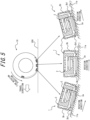
- FIG. 5 is a diagram illustrating deformation of the tire sensor 1 associated with deformation of the tire 10.
- the concave portion 3b1 that is formed in the side surface 3b of the cover body 3 can absorb stress that acts on the tire sensor 1 due to repeated tire deformation caused by contact with the road surface 200 during driving. Therefore, it is possible to prevent the entire tire sensor 1 from detaching from the tire inner surface by peeling off the mounting surface 3a from the tire inner surface due to the above tire deformation, and a part of the tire sensor 1 from floating and detaching from the tire inner surface due to damage to the cover body 3. That is, the provision of the concave portion 3b1 in the side surface 3b of the cover body 3 allows to realize the tire sensor 1 that is hard to detach from the tire inner surface even with the repeated tire deformation during driving.
- the housing 22 of this embodiment includes a circular bottom portion 31 and a cylindrical tubular portion 32 rising from an outer edge of the bottom portion 31.
- the housing 22 of this embodiment is composed in a bottomed cylindrical shape with an opening on only one side.
- the bottom portion 31 and the tubular portion 32 of this embodiment partition an accommodation space S that accommodates at least a part of the circuit member 21.
- an inner circumferential surface 32a of the tubular portion 32 that partitions the accommodation space S is a cylindrical surface with a constant diameter.
- an inner bottom surface 31a of the bottom portion 31 is a plane orthogonal to a central axis O of the inner circumferential surface 32a of the tubular portion 32.
- a plurality of annular convex portions 33 in which concavities and convexities are arranged in a row along the axial direction of the tubular portion 32 is formed in an outer circumferential surface 32b of the tubular portion 32.
- the annular convex portions 33 are provided in the tubular portion 32 on the side of the bottom portion 31, and are formed in plurality (three in this embodiment) at predetermined intervals in the axial direction.
- Each of the annular convex portions 33 is connected in an unterminated manner over the entire circumferential direction of the tubular portion 32.
- the annular convex portions 33 may be provided in an intermittent manner in the circumferential direction of the tubular portion 32.
- the base member 38 is composed of an elastomer such as rubber.
- a silicon rubber with a Shore A hardness of about 50 is used, but the thickness, hardness, material, and the like of the base member 38 may be changed as appropriate to enable detection of the strain with high accuracy.
- the convex portions 36 and the support portions 37 are disposed on the outer bottom surface 31b of the bottom portion 31 at different positions from the positions of the mounting portion 34 and the through hole 35 described above.
- the positions at which the convex portions 36 are disposed are not particularly limited.
- the two circuit boards 60 and 80 are arranged so as to face each other in the sensor height direction D.
- the circuit board 80 is located farther from the mounting surface 3a than the circuit board 60 in the sensor height direction D.
- first circuit board 60 the circuit board 60 located closer to the mounting surface 3a
- second circuit board 80 the circuit board 80 located farther from the mounting surface 3a
- the first circuit board 60 and the second circuit board 80 of this embodiment are electrically connected by a connection portion 78, such as coupling pins, for example, and constitute the integral electronic circuitry.
- the temperature detector 81 and the pressure detector 82 are mounted on the second circuit board 80, but may be connected to the second circuit board 80 via wiring. Furthermore, the temperature detector 81 and the pressure detector 82 may be mounted on or connected to the first circuit board 60. That is, when a detector 61 that is mounted on or connected to the first circuit board 60 is referred to as "first detector” and a detector 61 that is mounted on or connected to the second circuit board 80 is referred to as "second detector", the temperature detector 81 and the pressure detector 82 may be first detectors or second detectors.
- the memory is realized, for example, by a random access memory (RAM) or a read-only memory (ROM).
- the memory stores, for example, a unique identification number set on the second circuit board 80, programs for controlling the operations of the temperature detector 81, pressure detector 82, and strain detector 62, a program for operating the communication interface 67, a program for executing processing when the communication interface 67 receives signals from outside, a program for controlling the first circuit board 60, and the like.
- the memory also stores the tire information detected by the temperature detector 81, pressure detector 82, and strain detector 62.
- the strain amplifier 65 includes a signal amplification circuit 65a, an A/D converter 65b, a power supply unit 65c, and the like.
- the signal amplification circuit 65a amplifies the signal input from the bridge circuit 64.
- the A/D converter 65b converts the signal amplified by the signal amplification circuit 65a into a digital signal and outputs the digital signal to the first circuit board 60. That is, the strain amplifier 65 outputs, to the first circuit board 60, a voltage value corresponding to the amount of the strain detected by the strain gage 63 as the digital signal.
- the power source 23 of this embodiment is a battery. More specifically, the power source 23 of this embodiment is constituted of a disc-shaped button battery. However, the configuration of the power source 23 is not particularly limited.
- the electronic circuitry of the circuit member 21 operates by receiving power supply from the power source 23. More specifically, the power source 23 of this embodiment is connected to the first circuit board 60. The power source 23 of this embodiment feeds power directly to the first circuit board 60.
- the second circuit board 80 is indirectly powered by the power source 23 via the first circuit board 60.
- the battery as the power source 23 may be connected to the second circuit board 80.
- the cover body 3 covers at least a part of the periphery of the sensor body 2. Specifically, the cover body 3 of this embodiment covers almost the entire periphery of the sensor body 2. More specifically, the cover body 3 of this embodiment has connection holes to realize temperature detection by the temperature detector 81 and pressure detection by the pressure detector 82. The cover body 3 of this embodiment covers the entire periphery of the sensor body 2 at positions other than these connection holes.
- the cover body 3 of this embodiment is composed of polyester resin, but the material of the cover body 3 is not particularly limited.
- the cover body 3 is preferably made of an elastomer, considering followability to deformation of the tire 10.
- the concave portion 3b1 in the side surface 3b is not limited to the annular groove of this embodiment.
- the concave portion 3b1 in the side surface 3b only needs to be formed at least a part of the side surface 3b in the circumferential direction (in this embodiment, the same direction as the sensor circumferential direction F).
- the mounting surface 3a of the tire sensor 1 should be mounted on the tire inner circumferential surface 11a so that a position at which the concave portion 3b1 is formed in the sensor circumferential direction F is aligned with the tire circumferential direction B.
- the cover body 3 of this embodiment includes an annular cover portion 42 made of an elastomer, which covers the periphery of the sensor body 2 in the plan view along the sensor height direction D (see FIG. 2 ).
- the annular cover portion 42 of this embodiment is integrally connected from an outer edge of the pedestal portion 41.
- the side surface 3b of the cover body 3 of this embodiment is constituted of an outer surface 42a of the annular cover portion 42. That is, in this embodiment, the concave portion 3b1 is formed in the outer surface 42a of the annular cover portion 42.
Landscapes
- Engineering & Computer Science (AREA)
- Mechanical Engineering (AREA)
- Physics & Mathematics (AREA)
- General Physics & Mathematics (AREA)
- Tires In General (AREA)
- Measuring Fluid Pressure (AREA)
Abstract
Description
- The present disclosure relates to a tire sensor and a tire.
- Technology for mounting tire sensors on inner surfaces of tires for the purpose of detecting temperature and pressure inside the tires is known. Patent Literature (PTL) 1 discloses this type of tire sensor.
- PTL 1:
JP 2013-226853 A - Tires are repeatedly deformed by contact with road surfaces during driving. Therefore, tire sensors mounted on inner surfaces of the tires are required to have durability (hereinafter referred to as "tire sensor durability") so that the tire sensors are not detached even with the above-described repeated deformation of the tires. In the tire sensor described in
PTL 1, the tire sensor durability is enhanced by a groove provided in a rubber base. However, even in the tire sensor described inPTL 1, there is still room for improvement with respect to the tire sensor durability. - It would be helpful to provide a tire sensor with improved durability, and a tire.
- A tire sensor as a first aspect of the present disclosure is a tire sensor configured to be mountable on a tire inner surface. The tire sensor includes a sensor body including electronic circuitry including a detector configured to be able to detect tire information, and a cover body configured to cover at least a part of a periphery of the sensor body. The cover body includes a mounting surface configured to be mountable on the tire inner surface, and a side surface configured to rise from an outer edge of the mounting surface. In the side surface of the cover body, a concave portion is formed between the mounting surface and a height position of 1/4 of a maximum sensor height in a sensor height direction orthogonal to the mounting surface.
- A tire as a second aspect of the present disclosure includes the tire sensor described above.
- According to the present disclosure, it is possible to provide a tire sensor with improved durability, and a tire.
- In the accompanying drawings:
-
FIG. 1 is a tire-width-directional cross-sectional view of a tire, as an embodiment of the present disclosure, that includes a tire sensor as an embodiment of the present disclosure; -
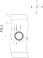
FIG. 2 is a diagram in which the tire sensor illustrated inFIG. 1 is viewed from the side of an inner space of the tire; -
FIG. 3 is a cross-sectional view of the tire sensor in a cross-section along a sensor height direction; -
FIG. 4 is an enlarged cross-sectional view of a part ofFIG. 3 ; -
FIG. 5 is a diagram illustrating deformation of the tire sensor illustrated inFIG. 1 associated with deformation of the tire illustrated inFIG. 1 ; -
FIG. 6 is a diagram illustrating details on a detection body of a strain detector illustrated inFIG. 4 ; and -
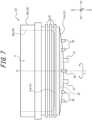
FIG. 7 is a side view of a housing, by itself, illustrated inFIG. 3 . - Embodiments of a tire sensor and a tire according to the present disclosure will be exemplarily described below with reference to the drawings. In each of the drawings, the same configurations are denoted with the same reference signs.
-
FIG. 1 is a tire-width-directional cross-sectional view of a pneumatic tire 10 (hereinafter referred to as "tire 10"), as an embodiment of the tire according to the present disclosure.FIG. 1 illustrates a state of thetire 10 assembled on arim 15. Aninner space 10a of thetire 10 is filled with a gas such as air. As illustrated inFIG. 1 , thetire 10 includes atire sensor 1, as an embodiment of the tire sensor according to the present disclosure.FIG. 2 is a diagram in which thetire sensor 1 illustrated inFIG. 1 is seen from the side of theinner space 10a of thetire 10. Here, "tire-width-directional cross-section" means a cross-section parallel to a tire width direction A at a position including a central axial line of thetire 10.FIG. 1 is a tire-width-directional cross-sectional view of thetire 10 that passes through a position at which thetire sensor 1 is located in a tire circumferential direction B. - In this specification, "rim" means a standard rim (Measuring Rim in ETRTO's STANDARDS MANUAL and Design Rim in TRA's YEAR BOOK) of an applicable size conformable to industrial standards valid for regions in which tires are produced and used, as described in or to be described in JATMA YEAR BOOK of the JATMA (The Japan Automobile Tyre Manufacturers Association, Inc.) in Japan, STANDARDS MANUAL of the ETRTO (The European Tyre and Rim Technical Organisation) in Europe, YEAR BOOK of TRA (The Tire and Rim Association, Inc.) in the United States, or the like, but in the case of a size that is not listed in such industrial standards, a rim with a width corresponding to a bead width of the tire. "Rim" may be of a size that may be included in the above industrial standards in the future, as well as a current size. Examples of the "size that is included in the future" may be sizes listed as "FUTURE DEVELOPMENTS" in the 2013 edition of STANDARDS MANUAL of the ETRTO.
- As illustrated in
FIGS. 1 and2 , thetire sensor 1 is secured on a tire inner surface with an adhesive. Thetire sensor 1 of this embodiment is mounted on a tire innercircumferential surface 11a, as the tire inner surface, which is a back side of atread 11 of thetire 10 that contacts a road surface 200 (seeFIG. 5 ). Thetire sensor 1 is mounted on a middle of the tire innercircumferential surface 11a in the tire width direction A. More specifically, thetire sensor 1 is mounted on the tire innercircumferential surface 11a at a position that intersects a tire equatorial plane CL. - In this specification, "tread inner circumferential surface" means an inner surface located on a back side of a tire outer circumferential surface over the entire circumference of the tire, which is in contact with the road surface when the tire that is assembled on the rim and filled with a specified internal pressure is rotated under a condition with a maximum load (hereinafter also referred to as "maximum load condition").
- In this specification, the above "specified internal pressure" refers to an air pressure (maximum air pressure) corresponding to a maximum load capacity of a single wheel in an applicable size and ply rating described in the above JATMA YEAR BOOK and other industrial standards, and in the case of a size not described in the above industrial standards, an air pressure (maximum air pressure) corresponding to a maximum load capacity specified for each vehicle on which the tire is mounted. In this specification, "maximum load" means a load corresponding to a maximum load capacity in the tire of an applicable size listed in the above industrial standards, and in the case of a size not listed in the above industrial standards, a load corresponding to a maximum load capacity specified for each vehicle on which the tire is mounted.
- The type of
tire 10 on which thetire sensor 1 is mounted is not particularly limited. Examples of thetire 10 include, for example, tires of passenger cars, trucks, buses, other automobiles, aircraft, and other vehicles that primarily travel on normal paved roads (general roads and highways). - The type of
tire sensor 1 is not particularly limited. Thetire sensor 1 may be, for example, a strain sensor that can detect a strain of thetire 10 as tire information. Thetire sensor 1 may be, for example, a temperature sensor that can detect, as the tire information, the temperature of theinner space 10a of thetire 10. Furthermore, thetire sensor 1 may be, for example, a pressure sensor that can detect, as the tire information, the pressure of theinner space 10a of thetire 10. Thetire sensor 1 may be, for example, a combined sensor that can detect two or more of the strain of thetire 10, the temperature of theinner space 10a of thetire 10, and the pressure of theinner space 10a of thetire 10. Thetire sensor 1 may also be configured to be able to detect tire information such as an acceleration, for example, other than the tire information described above. - The
tire sensor 1 is configured to be able to transmit the detected tire information to an external device, such as, for example, an in-vehicle device installed in a vehicle. Various signals of the tire information transmitted wirelessly from thetire sensor 1 may be received, for example, by radio circuitry of the in-vehicle device. The received tire information, information indicating the condition of the tire obtained based on this tire information, or the like may be displayed on a display unit provided in the vehicle. However, applications, display methods, and the like of the tire information detected by thetire sensor 1 are not particularly limited. -
FIG. 3 is a cross-sectional view of thetire sensor 1.FIG. 4 is an enlarged cross-sectional view of a part ofFIG. 3 . As illustrated inFIGS. 3 and4 , thetire sensor 1 includes asensor body 2 and acover body 3. - The
sensor body 2 includes electronic circuitry including adetector 61 that can detect the tire information. More specifically, thesensor body 2 according to this embodiment includes acircuit member 21, ahousing 22, and apower source 23. - The
circuit member 21 constitutes the electronic circuitry including thedetector 61. Thecircuit member 21 may be, for example, a sensor module. That is, thecircuit member 21 includes a plurality of electronic components that constitute the electronic circuitry including thedetector 61. As will be described in detail below, thecircuit member 21 according to this embodiment includescircuit boards - The
housing 22 supports thecircuit member 21. Thehousing 22 is composed of an insulator. Thehousing 22 is preferably composed of a resin material. The resin material composing thehousing 22 is, for example, a nylon-based resin material such as polyphthalamide. - The
power source 23 provides electric power to the electronic circuitry constituted of thecircuit member 21. Thepower source 23 is, for example, a battery. - The
cover body 3 covers at least a part of a periphery of thesensor body 2. Thecover body 3 includes a mountingsurface 3a that can be mounted on the tire inner surface, and aside surface 3b that rises from an outer edge of the mountingsurface 3a. - As illustrated in
FIGS. 1 and3 , a concave portion 3b1 is formed in theside surface 3b of thecover body 3.FIG. 5 is a diagram illustrating deformation of thetire sensor 1 associated with deformation of thetire 10. As illustrated inFIG. 5 , the concave portion 3b1 that is formed in theside surface 3b of thecover body 3 can absorb stress that acts on thetire sensor 1 due to repeated tire deformation caused by contact with theroad surface 200 during driving. Therefore, it is possible to prevent theentire tire sensor 1 from detaching from the tire inner surface by peeling off the mountingsurface 3a from the tire inner surface due to the above tire deformation, and a part of thetire sensor 1 from floating and detaching from the tire inner surface due to damage to thecover body 3. That is, the provision of the concave portion 3b1 in theside surface 3b of thecover body 3 allows to realize thetire sensor 1 that is hard to detach from the tire inner surface even with the repeated tire deformation during driving. - The concave portion 3b1 is formed between the mounting
surface 3a and a height position of 1/4 of a maximum sensor height Hmax in a sensor height direction D orthogonal to the mountingsurface 3a. In other words, the concave portion 3b1 is formed close to the mountingsurface 3a in the sensor height direction D. Therefore, a force (hereinafter referred to as "detachment force") that acts in the vicinity of the mountingsurface 3a due to the tire deformation to detach thetire sensor 1 from the tire inner surface is easily absorbed by the concave portion 3b1. This can further prevent the detachment of thetire sensor 1 from the tire inner surface. The concave portion 3b1 is more preferably formed between the mountingsurface 3a and a height position of 1/5 of the maximum sensor height Hmax in the sensor height direction D orthogonal to the mountingsurface 3a. Note that, the sensor height direction D in this embodiment is the same direction as a tire radial direction C when thetire sensor 1 is mounted on the tire innercircumferential surface 11a as in this embodiment. - Thus, the provision of the concave portion 3b1 in the
side surface 3b of thecover body 3 at the height position described above can increase the durability of thetire sensor 1. - Further details on the
tire sensor 1 of this embodiment will be described below with reference toFIGS. 1 to 7 .FIG. 6 is a diagram illustrating details on adetection body 62b of astrain detector 62 of thesensor body 2.FIG. 7 is a side view of thehousing 22, by itself, of thesensor body 2. - As illustrated in
FIG. 7 and the like, thehousing 22 of this embodiment includes acircular bottom portion 31 and a cylindricaltubular portion 32 rising from an outer edge of thebottom portion 31. In other words, thehousing 22 of this embodiment is composed in a bottomed cylindrical shape with an opening on only one side. Thebottom portion 31 and thetubular portion 32 of this embodiment partition an accommodation space S that accommodates at least a part of thecircuit member 21. In this embodiment, an innercircumferential surface 32a of thetubular portion 32 that partitions the accommodation space S is a cylindrical surface with a constant diameter. In this embodiment, aninner bottom surface 31a of thebottom portion 31 is a plane orthogonal to a central axis O of the innercircumferential surface 32a of thetubular portion 32. Theinner bottom surface 31a of thebottom portion 31 and the innercircumferential surface 32a of thetubular portion 32 may be provided with latch portions, such as projections, to support thecircuit member 21 when thecircuit member 21 is accommodated in the accommodation space S. Thehousing 22 is composed of synthetic resin, for example, from the viewpoint of reduced weight and increased strength of thetire sensor 1. The material composing thehousing 22 can be changed as appropriate from the viewpoint of reduction in the weight and increase in the strength of thetire sensor 1. However, thehousing 22 of this embodiment is configured with higher stiffness than at least thecover body 3. - The
housing 22 of this embodiment is disposed so that an axial direction parallel to the central axis O of thetubular portion 32 coincides with the sensor height direction D of thetire sensor 1. Therefore, in this embodiment, a sensor width direction E, which is orthogonal to the sensor height direction D, of thetire sensor 1 coincides with a radial direction of thetubular portion 32. In this embodiment, in a plan view of thetire sensor 1 along the sensor height direction D (seeFIG. 2 ), a sensor circumferential direction F along an outer edge of thetire sensor 1 coincides with a circumferential direction of thetubular portion 32. - A plurality of annular
convex portions 33 in which concavities and convexities are arranged in a row along the axial direction of thetubular portion 32 is formed in an outercircumferential surface 32b of thetubular portion 32. The annularconvex portions 33 are provided in thetubular portion 32 on the side of thebottom portion 31, and are formed in plurality (three in this embodiment) at predetermined intervals in the axial direction. Each of the annularconvex portions 33 is connected in an unterminated manner over the entire circumferential direction of thetubular portion 32. However, the annularconvex portions 33 may be provided in an intermittent manner in the circumferential direction of thetubular portion 32. - As illustrated in
FIGS. 3 and7 , an outerbottom surface 31b of thebottom portion 31 is composed of a convex surface that expands outward in the axial direction of thetubular portion 32 at a center side of the outerbottom surface 31b relative to an outer edge side thereof. More specifically, the outerbottom surface 31b of this embodiment is composed of a spherical curved surface. However, the shape of the outerbottom surface 31b is not particularly limited. The outerbottom surface 31b may be, for example, a conical surface, a truncated conical surface, or some other curved surface. The outerbottom surface 31b may be, for example, a flat surface orthogonal to the axial direction. As illustrated inFIG. 1 , the outerbottom surface 31b of thebottom portion 31 is a surface facing the tire innercircumferential surface 11a of thetire 10 when thetire sensor 1 is mounted on the tire innercircumferential surface 11a of thetire 10. - The outer
bottom surface 31b of thebottom portion 31 includes a mountingportion 34 on which thestrain detector 62, as thedetector 61 of thecircuit member 21, is mounted. In thebottom portion 31, a throughhole 35 that penetrates from the outerbottom surface 31b to theinner bottom surface 31a is formed. Further, thebottom portion 31 includes a plurality ofconvex portions 36 and a plurality ofsupport portions 37 that protrude from the outerbottom surface 31b. - The mounting
portion 34 is composed of a concave portion provided in the outerbottom surface 31b at a position through which the central axis O of thetubular portion 32 passes. A bottom surface of the concave portion, as the mountingportion 34, is, for example, a plane orthogonal to the axial direction of thetubular portion 32. As illustrated inFIG. 4 , abase member 38, which serves as a foundation for mounting thestrain detector 62 as thedetector 61, is disposed on the mountingportion 34. - The
base member 38 is composed of, for example, a flat plate member that conforms to the shape of the mountingportion 34 of the outerbottom surface 31b and is partially embedded. Thebase member 38 is, for example, secured to the mountingportion 34 with an adhesive or the like. When thebase member 38 is secured to the mountingportion 34, adetector mounting surface 38a of thebase member 38, on which thestrain detector 62 is mounted, is exposed outside the concave portion, as the mountingportion 34. Therefore, when thestrain detector 62 is mounted on thedetector mounting surface 38a of thebase member 38, thestrain detector 62 is exposed so as to protrude from the outerbottom surface 31b. A strain of thetire 10 caused by rotation of thetire 10 can be thereby detected with high accuracy. Thebase member 38 is composed of an elastomer such as rubber. In this embodiment, a silicon rubber with a Shore A hardness of about 50 is used, but the thickness, hardness, material, and the like of thebase member 38 may be changed as appropriate to enable detection of the strain with high accuracy. - As illustrated in
FIG. 4 , the throughhole 35 is disposed so as to be connected to the mountingportion 34. The throughhole 35 extends along the axial direction of thetubular portion 32 from theinner bottom surface 31a to the outerbottom surface 31b of thehousing 22. Into the throughhole 35, wiring 88 that connects thestrain detector 62 to other electronic components constituting the electronic circuitry is inserted. - As illustrated in
FIG. 7 , theconvex portions 36 and thesupport portions 37 are disposed on the outerbottom surface 31b of thebottom portion 31 at different positions from the positions of the mountingportion 34 and the throughhole 35 described above. The positions at which theconvex portions 36 are disposed are not particularly limited. - The
convex portions 36 of this embodiment are cylindrical, but are not limited to this shape. Theconvex portions 36 may be, for example, polygonal columnar, conical, truncated conical, or the like. In the outerbottom surface 31b, for example, a plurality of concave portions may be formed, instead of or in addition to theconvex portions 36. The provision of suchconvex portions 36 or concave portions can increase securing strength to thecover body 3. - The extension length of each
support portion 37 is set so that a tip of thesupport portion 37 protrudes from a surface of thestrain detector 62 when thestrain detector 62 is mounted on thehousing 22. This prevents a gap between thestrain detector 62 and the tire inner surface from becoming excessively narrow due to, for example, a centrifugal force of thetire 10, or the like. - As illustrated in
FIG. 3 , thecircuit member 21 of this embodiment includes the twocircuit boards circuit boards above housing 22. As illustrated inFIG. 3 , thecircuit boards strain detector 62 as thedetector 61, constitute the electronic circuitry. - In addition to the
strain detector 62, thecircuit member 21 of this embodiment includes a plurality ofdetectors 61. Specifically, thecircuit member 21 of this embodiment includes atemperature detector 81 that detects the temperature of theinner space 10a of thetire 10. Furthermore, thecircuit member 21 of this embodiment includes apressure detector 82 that detects the pressure of theinner space 10a of thetire 10. Therefore, thecircuit boards strain detector 62, thetemperature detector 81, and thepressure detector 82. Each of thestrain detector 62,temperature detector 81, andpressure detector 82 may be constituted of various electronic components mounted on or connected to thecircuit board circuit member 21 may be configured with only a part of the abovevarious detectors 61. Thecircuit member 21 may include someother detector 61, such as an acceleration detector, in addition to or instead of the abovevarious detectors 61. - The two
circuit boards circuit board 80 is located farther from the mountingsurface 3a than thecircuit board 60 in the sensor height direction D. For convenience of explanation, thecircuit board 60 located closer to the mountingsurface 3a is referred to as "first circuit board 60", and thecircuit board 80 located farther from the mountingsurface 3a is referred to as "second circuit board 80". Thefirst circuit board 60 and thesecond circuit board 80 of this embodiment are electrically connected by aconnection portion 78, such as coupling pins, for example, and constitute the integral electronic circuitry. - In this embodiment, the
temperature detector 81 and thepressure detector 82 are mounted on thesecond circuit board 80. Acontroller 70 and acommunication interface 67, which are described later, are also mounted on thesecond circuit board 80. Since thecommunication interface 67 is mounted on thesecond circuit board 80, radio waves transmitted from thecommunication interface 67 are less likely to be blocked, compared to a configuration in which thecommunication interface 67 is mounted on thefirst circuit board 60, which is disposed between thesecond circuit board 80 and the tire inner surface. This can enhance the communicability of thetire sensor 1. - In this embodiment, the
strain detector 62 is connected to thefirst circuit board 60 via thewiring 88. As in this embodiment, thestrain detector 62 is preferably connected to thefirst circuit board 60, which is disposed closer to the tire inner surface than thesecond circuit board 80, when thetire sensor 1 is mounted on the tire inner surface (seeFIG. 1 ). This can shorten the distance of thewiring 88 and thus simplify the circuit configuration. - As described above, in this embodiment, the
temperature detector 81 and thepressure detector 82 are mounted on thesecond circuit board 80, but may be connected to thesecond circuit board 80 via wiring. Furthermore, thetemperature detector 81 and thepressure detector 82 may be mounted on or connected to thefirst circuit board 60. That is, when adetector 61 that is mounted on or connected to thefirst circuit board 60 is referred to as "first detector" and adetector 61 that is mounted on or connected to thesecond circuit board 80 is referred to as "second detector", thetemperature detector 81 and thepressure detector 82 may be first detectors or second detectors. - The
circuit member 21 of this embodiment includes thecontroller 70 that processes the tire information detected by the abovevarious detectors 61. Thecontroller 70 of this embodiment controls operations of thetemperature detector 81, thepressure detector 82, and thestrain detector 62. Furthermore, thecontroller 70 of this embodiment controls operations of thecommunication interface 67. Thecontroller 70 of this embodiment is mounted on thesecond circuit board 80 as described above, but may be mounted on thefirst circuit board 60. - The
controller 70 is configured, for example, as a one-chip IC that functions as a so-called computer, or the like. Specifically, thecontroller 70 includes one or more processors, memory, and the like. - The one or more processors may be realized by dedicated processors specialized for detection processing by the
various detectors 61. The one or more processors may be realized by general-purpose processors such as Central Processing Units (CPUs). - The memory is realized, for example, by a random access memory (RAM) or a read-only memory (ROM). The memory stores, for example, a unique identification number set on the
second circuit board 80, programs for controlling the operations of thetemperature detector 81,pressure detector 82, andstrain detector 62, a program for operating thecommunication interface 67, a program for executing processing when thecommunication interface 67 receives signals from outside, a program for controlling thefirst circuit board 60, and the like. The memory also stores the tire information detected by thetemperature detector 81,pressure detector 82, andstrain detector 62. - Furthermore, the
circuit member 21 of this embodiment includes thecommunication interface 67. Thecommunication interface 67 can transmit the tire information detected by thevarious detectors 61, or secondary information processed by thecontroller 70 based on this tire information, to an external device. More specifically, thecommunication interface 67 of this embodiment can transmit information input from thecontroller 70 to the external device such as an in-vehicle device. The various tire information or secondary information signals transmitted wirelessly from thecommunication interface 67 are received, for example, by radio circuitry of the in-vehicle device, and displayed on a display unit provided in a vehicle, as information regarding the condition of thetire 10, such as the temperature, pressure, presence or absence of an abnormality in thetire 10, and the like. Thecommunication interface 67 of this embodiment can receive information from the outside and output the received information to thecontroller 70. - The
communication interface 67 may be constituted of, for example, a transmission circuit, a transmission antenna, a reception circuit, and a reception antenna. - The
temperature detector 81, thepressure detector 82, and a control circuit of thecontroller 70, and the transmission and reception circuits of thecommunication interface 67 described above may be integrated as a sensor unit in which functions are integrated into a single chip. In such a case, the sensor unit is mounted on thefirst circuit board 60 or thesecond circuit board 80. The transmission and reception antennas of thecommunication interface 67 may be provided as an antenna unit, separate from the sensor unit. In such a case, this antenna unit is mounted on thefirst circuit board 60 or thesecond circuit board 80. - As described above, the
strain detector 62 of this embodiment is connected to thefirst circuit board 60 via thewiring 88. More specifically, as illustrated inFIG. 4 , thestrain detector 62 of this embodiment includes asensing piece 62a and adetection body 62b. Thesensing piece 62a is made of, for example, a thin metal plate with elasticity. Thesensing piece 62a of this embodiment is disposed on thedetector mounting surface 38a of thebase member 38. Furthermore, thesensing piece 62a of this embodiment is extended into the throughhole 35 from a portion disposed on thedetector mounting surface 38a of thebase member 38. This extended portion extends into the accommodation space S and is latched onto thehousing 22. Thestrain detector 62 of this embodiment is thereby supported by thehousing 22. - The
detection body 62b is mounted on a surface of thesensing piece 62a on an opposite side of the base member 38 (a lower surface of thesensing piece 62a inFIG. 4 ). Thedetection body 62b detects a strain of thetire 10 that occurs when thetire 10 is stepped on or kicked out, through deformation of thesensing piece 62a as thetire 10 rotates. Since thedetection body 62b is mounted on the surface of thesensing piece 62a on the opposite side of the base member 38 (the lower surface of thesensing piece 62a inFIG. 4 ), measurement accuracy of thedetection body 62b is improved, compared to a configuration in which thedetection body 62b is mounted on a surface of thesensing piece 62a on the side of the base member 38 (an upper surface of thesensing piece 62a inFIG. 4 ). However, thedetection body 62b may be mounted on the surface of thesensing piece 62a on the side of the base member 38 (the upper surface of thesensing piece 62a inFIG. 4 ). This configuration improves the durability of thedetection body 62b, compared to the configuration in which thedetection body 62b is mounted on the surface of thesensing piece 62a on the opposite side of the base member 38 (the lower surface of thesensing piece 62a inFIG. 4 ). - As illustrated in
FIG. 6 , thedetection body 62b includes, for example, astrain gage 63, abridge circuit 64, astrain amplifier 65, and the like. Thestrain gage 63 constitutes a part of thebridge circuit 64. A voltage is applied to thebridge circuit 64, for example, from thestrain amplifier 65, and a difference in a voltage value resulting from a change in resistance when thestrain gage 63 detects a strain is output to thestrain amplifier 65 as a signal. - The
strain amplifier 65 includes asignal amplification circuit 65a, an A/D converter 65b, apower supply unit 65c, and the like. Thesignal amplification circuit 65a amplifies the signal input from thebridge circuit 64. The A/D converter 65b converts the signal amplified by thesignal amplification circuit 65a into a digital signal and outputs the digital signal to thefirst circuit board 60. That is, thestrain amplifier 65 outputs, to thefirst circuit board 60, a voltage value corresponding to the amount of the strain detected by thestrain gage 63 as the digital signal. - The
detection body 62b of thestrain detector 62 may be, for example, a sensor chip that integrates the functions of thestrain gage 63,bridge circuit 64, andstrain amplifier 65 on a single chip as a rectangular so-called piezoresistive semiconductor. This sensor chip may be mounted, for example, with a measurement surface defined and this measurement surface facing a surface of thesensing piece 62a. - The
power source 23 of this embodiment is a battery. More specifically, thepower source 23 of this embodiment is constituted of a disc-shaped button battery. However, the configuration of thepower source 23 is not particularly limited. The electronic circuitry of thecircuit member 21 operates by receiving power supply from thepower source 23. More specifically, thepower source 23 of this embodiment is connected to thefirst circuit board 60. Thepower source 23 of this embodiment feeds power directly to thefirst circuit board 60. Thesecond circuit board 80 is indirectly powered by thepower source 23 via thefirst circuit board 60. However, the battery as thepower source 23 may be connected to thesecond circuit board 80. - As illustrated in
FIG. 3 , thecover body 3 covers at least a part of the periphery of thesensor body 2. Specifically, thecover body 3 of this embodiment covers almost the entire periphery of thesensor body 2. More specifically, thecover body 3 of this embodiment has connection holes to realize temperature detection by thetemperature detector 81 and pressure detection by thepressure detector 82. Thecover body 3 of this embodiment covers the entire periphery of thesensor body 2 at positions other than these connection holes. - The
cover body 3 of this embodiment is composed of polyester resin, but the material of thecover body 3 is not particularly limited. Thecover body 3 is preferably made of an elastomer, considering followability to deformation of thetire 10. - As described above, the
cover body 3 includes theside surface 3b in which the concave portion 3b1 is formed at the predetermined position in the sensor height direction D. As illustrated inFIG. 3 , the concave portion 3b1 of this embodiment is located between the mountingsurface 3a and thesecond circuit board 80 in the sensor height direction D. Furthermore, the concave portion 3b1 of this embodiment is located between the mountingsurface 3a and thefirst circuit board 60, which is disposed closest to the mountingsurface 3a among the plurality (two in this embodiment) of circuit boards, in the sensor height direction D. The concave portion 3b1 is thereby easily disposed close to the mountingsurface 3a in the sensor height direction D. Therefore, in thecover body 3, the thickness between the mountingsurface 3a and the concave portion 3b1 in the sensor height direction D tends to be small. In other words, the concave portion 3b1 is easily disposed close to the tire inner surface. By disposing the concave portion 3b1 close to the tire inner surface, stress of thecover body 3 due to tire deformation is more easily absorbed by the concave portion 3b1. - As described above, the
sensor body 2 of this embodiment includes thestrain detector 62 as thedetector 61. Thestrain detector 62 is preferably disposed close to the tire inner surface from the viewpoint of improving measurement accuracy. Therefore, in this embodiment, the position of a surface of thestrain detector 62 on the side of the mountingsurface 3a of thecover body 3 is disposed closer to the mountingsurface 3a than theconcave portion 3bcover body 3 in the sensor height direction D. However, from the viewpoint of improving durability, the position of the surface of thestrain detector 62 on the side of the mountingsurface 3a of thecover body 3 may be disposed farther from the mountingsurface 3a than theconcave portion 3bcover body 3 in the sensor height direction D. - Furthermore, the
tubular portion 32 of thehousing 22 of this embodiment is disposed farther from the mountingsurface 3a than theconcave portion 3bcover body 3 in the sensor height direction D. Thereby, the concave portion 3b1 is more easily deformed, compared to a configuration in which thetubular portion 32 of thehousing 22 is disposed over both sides of the concave portion 3b1 in the sensor height direction D. That is, when theconcave portion 3bcover body 3, bending stress is less likely to occur in thetubular portion 32 of thehousing 22. Therefore, the ability of theconcave portion 3bcover body 3 can be increased. In addition, the configuration in which bending stress is less likely to occur in thetubular portion 32 owing to the deformation of thecover body 3 at theconcave portion 3bcircuit member 21 in thetubular portion 32, thereby preventing damage or the like to the electronic components constituting the electronic circuitry. - Furthermore, as illustrated in
FIG. 2 , in the plan view of thetire sensor 1 along the sensor height direction D, the position of theconcave portion 3bfirst circuit board 60. In the same plan view (seeFIG. 2 ), the position of theconcave portion 3bsecond circuit board 80. Here, the "position" in the "plan view of thetire sensor 1 along the sensor height direction D" means not only the position of a portion that can be seen in the above plan view, but also a position at which an invisible portion is projected on a paper surface. InFIG. 2 , for convenience of explanation, a colored (grayscale) area indicates the position of theconcave portion 3bconcave portion 3bFIG. 2 , dashed lines indicate the position of the outer edge of thefirst circuit board 60 and the position of the outer edge of thesecond circuit board 80. Note that, the position of the outer edge of thefirst circuit board 60 and the position of the outer edge of thesecond circuit board 80 in this embodiment overlap in the plan view illustrated inFIG. 2 , but are not limited to this configuration. - However, in the plan view of the
tire sensor 1 along the sensor height direction D (seeFIG. 2 ), the position of theconcave portion 3bfirst circuit board 60, or may be inside the outer edge of thefirst circuit board 60. In the same plan view (seeFIG. 2 ), the position of the concave portion 3b1 may be across the outside and inside of the outer edge of thesecond circuit board 80, or may be inside the outer edge of thesecond circuit board 80. - As illustrated in
FIG. 2 , thetubular portion 32 of thehousing 22 of this embodiment surrounds thefirst circuit board 60 in the plan view of thetire sensor 1 along the sensor height direction D. As illustrated inFIG. 2 , thetubular portion 32 of thehousing 22 of this embodiment surrounds thesecond circuit board 80 in the plan view of thetire sensor 1 along the sensor height direction D. In the same plan view (seeFIG. 2 ), the position of the concave portion 3b1 in theside surface 3b of thecover body 3 is across the outside and inside of thetubular portion 32 of thehousing 22. InFIG. 2 , the outside of thetubular portion 32 means the outside of the outercircumferential surface 32b of thetubular portion 32. InFIG. 2 , the inside of thetubular portion 32 means the inside of the innercircumferential surface 32a of thetubular portion 32. - As illustrated in
FIG. 3 , a maximum width W1 of theside surface 3b on the side of the mountingsurface 3a with respect to the concave portion 3b1 in the sensor height direction D is preferably 0.8 times to 1.2 times a maximum width W2 of theside surface 3b on the side of thefirst circuit board 60 and thesecond circuit board 80 with respect to the concave portion 3b1 in the sensor height direction D. The "maximum width of theside surface 3b" means a maximum length in the sensor width direction E. - Setting the maximum width W1 to be 0.8 times or more the maximum width W2 can prevent the center of gravity of the
tire sensor 1 from being biased to an upside in the sensor height direction D, i.e., to an inside in the tire radial direction C when thetire sensor 1 is mounted on the tire innercircumferential surface 11a (seeFIG. 1 ). That is, excessive vibration of thetire sensor 1 in the sensor width direction E can be prevented. This can further improve the durability of thetire sensor 1. In addition, setting the maximum width W1 to be 1.2 times or less the maximum width W2 can prevent an increase in the weight of thetire sensor 1 itself. Therefore, it is also possible to prevent an increase in the weight of thetire 10 due to installation of thetire sensor 1. From the viewpoint of both improving the durability of thetire sensor 1 and preventing an increase in the weight of thetire sensor 1, it is particularly preferable that the maximum widths W1 and W2 are approximately equal. - As illustrated in
FIGS. 2 and3 , the concave portion 3b1 of this embodiment is an annular groove extending over theentire side surface 3b in the circumferential direction (in this embodiment, the same direction as the sensor circumferential direction F). By configuring the concave portion 3b1 as the annular groove, stress on thecover body 3 can be absorbed in any sensor width direction E orthogonal to the sensor height direction D when thetire sensor 1 is mounted on the tire inner surface. - The concave portion 3b1 in the
side surface 3b is not limited to the annular groove of this embodiment. The concave portion 3b1 in theside surface 3b only needs to be formed at least a part of theside surface 3b in the circumferential direction (in this embodiment, the same direction as the sensor circumferential direction F). In such a case, the mountingsurface 3a of thetire sensor 1 should be mounted on the tire innercircumferential surface 11a so that a position at which the concave portion 3b1 is formed in the sensor circumferential direction F is aligned with the tire circumferential direction B. However, from the viewpoint of eliminating anisotropy in the sensor circumferential direction F and increasing the ability of the concave portion 3b1 of thecover body 3 to absorb stress, it is preferable that the concave portion 3b1 in theside surface 3b be an annular groove, as in this embodiment. - As illustrated in
FIG. 3 , thecover body 3 of this embodiment is interposed not only in the periphery of thesensor body 2 but also between thecircuit member 21, thehousing 22, and thepower source 23 of thesensor body 2. In other words, thesensor body 2 and thecover body 3 of this embodiment are integrally formed. Thecover body 3 is molded, for example, so as to cover the outside of theentire housing 22 while being filled into the accommodation space S by molding. - The
cover body 3 of this embodiment includes apedestal portion 41 made of an elastomer. Thepedestal portion 41 covers one side of thesensor body 2 in the sensor height direction D. Specifically, thepedestal portion 41 of this embodiment covers thestrain detector 62 in thecircuit member 21 and the outerbottom surface 31b of thehousing 22 in which thestrain detector 62 is disposed. Thepedestal portion 41 of this embodiment includes a facingsurface 41a that faces thesensor body 2, and the mountingsurface 3a located on the opposite side of this facingsurface 41a. A surface of thestrain detector 62 of this embodiment that faces the tire inner surface (in this embodiment, a surface of thedetection body 62b on the opposite side of thesensing piece 62a) is in contact with the facingsurface 41a. That is, thepedestal portion 41 of thecover body 3 is a portion that is interposed between thesensor body 2 and the tire inner surface when thetire sensor 1 is mounted on the tire inner surface. Thestrain detector 62 of this embodiment can detect, as the tire information, strain information on thetire 10 through thepedestal portion 41 of thecover body 3. This can uniform the distance between thestrain detector 62 and the tire inner surface, compared to a configuration in which thestrain detector 62 is bonded to the tire inner surface with an adhesive without interposing thepedestal portion 41. That is, it is possible to prevent the occurrence of individual differences in the accuracy of strain detection of thetire 10 by thetire sensor 1, due to a bonding process of thetire sensor 1 to the tire inner surface. - Note that, the mounting
surface 3a may be mounted on the tire inner surface, for example, by being bonded to the tire inner surface with an adhesive. More specifically, in this embodiment, the adhesive is applied over the entire mountingsurface 3a, and the entire mountingsurface 3a is bonded to the tire inner surface. As the adhesive, for example, an instant adhesive or the like may be used. As the adhesive, one that forms a thin adhesive layer between the mountingsurface 3a and the tire inner surface should be used. - The
cover body 3 of this embodiment includes anannular cover portion 42 made of an elastomer, which covers the periphery of thesensor body 2 in the plan view along the sensor height direction D (seeFIG. 2 ). Theannular cover portion 42 of this embodiment is integrally connected from an outer edge of thepedestal portion 41. Theside surface 3b of thecover body 3 of this embodiment is constituted of anouter surface 42a of theannular cover portion 42. That is, in this embodiment, the concave portion 3b1 is formed in theouter surface 42a of theannular cover portion 42. Thus, by forming the concave portion 3b1 in theannular cover portion 42 made of the elastomer, the concave portion 3b1 can be flexibly deformed, and the ability of the concave portion 3b1 to absorb stress on thecover body 3 can be further enhanced. - By filling the
cover body 3 so as to be interposed not only in the periphery of thesensor body 2 but also between thecircuit member 21, thehousing 22, and thepower source 23 in thesensor body 2, a manufacturing process of thetire sensor 1 can be simplified. Thehousing 22 of this embodiment includes the plurality of annularconvex portions 33 in the outside of thetubular portion 32. Furthermore, thehousing 22 of this embodiment includes the plurality ofconvex portions 36 on the outerbottom surface 31b of thebottom portion 31. The provision of the annularconvex portions 33 andconvex portions 36 prevent misalignment of thehousing 22 with respect to thecover body 3. That is, even when an external force is applied to thetire sensor 1 as thetire 10 rotates, misalignment between thehousing 22 and thecover body 3 can be prevented, and thehousing 22 and thecover body 3 can be more easily maintained in an integrated state. - The
cover body 3 only needs to cover at least a part of thesensor body 2 and include the mountingsurface 3a and theside surface 3b described above. That is, thecover body 3 is not limited to such a configuration that covers the entire periphery of thesensor body 2 as in this embodiment. Thecover body 3, for example, may not fill the accommodation space S of thehousing 22. That is, thecover body 3 may not cover a part of the periphery of thesensor body 2. An example of such acover body 3 is, for example, a configuration constituted of only thepedestal portion 41 and theannular cover portion 42 described above. - The tire sensor and the tire according to the present disclosure are not limited to the specific configurations described in the above embodiments, and various variations and modifications are possible without departing from the scope of the claims.
- The present disclosure relates to a tire sensor and a tire.
-
- 1
- tire sensor
- 2
- sensor body
- 3
- cover body
- 3a
- mounting surface
- 3b
- side surface
- 3b1
- concave portion
- 10
- tire
- 10a
- inner space
- 11
- tread
- 11a
- tire inner circumferential surface (tire inner surface)
- 15
- rim
- 21
- circuit member
- 22
- housing
- 23
- power source
- 31
- bottom portion
- 31a
- inner bottom surface
- 31b
- outer bottom surface
- 32
- tubular portion
- 32a
- inner circumferential surface
- 32b
- outer circumferential surface
- 33
- annular convex portion
- 34
- mounting portion
- 35
- through hole
- 36
- convex portion
- 37
- support portion
- 38
- base member
- 38a
- detector mounting surface
- 41
- pedestal portion
- 41a
- facing surface
- 42
- annular cover portion
- 42a
- outer surface
- 60
- first circuit board
- 61
- detector
- 62
- strain detector
- 62a
- sensing piece
- 62b
- detection body
- 63
- strain gage
- 64
- bridge circuit
- 65
- strain amplifier
- 65a
- signal amplification circuit
- 65b
- A/D converter
- 65c
- power supply unit
- 67
- communication interface
- 70
- controller
- 78
- connection portion
- 80
- second circuit board
- 81
- temperature detector
- 82
- pressure detector
- 88
- wiring
- 200
- road surface
- A
- tire width direction
- B
- tire circumferential direction
- C
- tire radial direction
- D
- sensor height direction
- E
- sensor width direction
- F
- sensor circumferential direction
- S
- accommodation space
- Hmax
- maximum sensor height
- O
- central axis of tubular portion of housing
- W1
- maximum width of side surface on mounting surface side with respect to concave portion
- W2
- maximum width of side surface on circuit board side with respect to concave portion
Claims (9)
- A tire sensor configured to be mountable on a tire inner surface, the tire sensor comprising:a sensor body comprising electronic circuitry comprising a detector configured to be able to detect tire information; anda cover body configured to cover at least a part of a periphery of the sensor body,whereinthe cover body comprises:a mounting surface configured to be mountable on the tire inner surface; anda side surface configured to rise from an outer edge of the mounting surface, andin the side surface of the cover body, a concave portion is formed between the mounting surface and a height position of 1/4 of a maximum sensor height in a sensor height direction orthogonal to the mounting surface.
- The tire sensor according to claim 1, whereinthe sensor body comprises a circuit board, andthe concave portion in the side surface of the cover body is located between the mounting surface and the circuit board of the sensor body in the sensor height direction.
- The tire sensor according to claim 2, wherein in a plan view along the sensor height direction, a position of the concave portion in the side surface of the cover body is outside an outer edge of the circuit board.
- The tire sensor according to claim 3, whereinthe sensor body comprises:a circuit member configured to constitute the electronic circuitry; anda housing configured to support the circuit member,the circuit member comprises the circuit board,the housing comprises a tubular portion configured to surround a periphery of the circuit board in the plan view, andin the plan view, the position of the concave portion in the side surface of the cover body is across outside and inside of the tubular portion of the housing.
- The tire sensor according to any one of claims 2 to 4, wherein a maximum width of the side surface on a side of the mounting surface with respect to the concave portion in the sensor height direction is 0.8 times to 1.2 times a maximum width of the side surface on a side of the circuit board with respect to the concave portion in the sensor height direction.
- The tire sensor according to any one of claims 1 to 5, wherein the concave portion in the side surface of the cover body is an annular groove extending over the entire side surface in a circumferential direction.
- The tire sensor according to any one of claims 1 to 6, whereinthe cover body comprises an annular cover portion made of an elastomer, the annular cover portion configured to cover the periphery of the sensor body in a plan view along the sensor height direction, andthe side surface of the cover body is constituted of an outer surface of the annular cover portion.
- The tire sensor according to any one of claims 1 to 7, whereinthe cover body comprises a pedestal portion made of an elastomer, the pedestal portion configured to cover one side of the sensor body in the sensor height direction,the pedestal portion comprises a facing surface configured to face the sensor body, and the mounting surface configured to be located on an opposite side of the facing surface, andthe detector of the sensor body is a strain detector configured to detect, as the tire information, strain information on a tire through the pedestal portion of the cover body.
- A tire comprising the tire sensor according to any one of claims 1 to 8.
Applications Claiming Priority (2)
| Application Number | Priority Date | Filing Date | Title |
|---|---|---|---|
| JP2021142712A JP2023035683A (en) | 2021-09-01 | 2021-09-01 | Tire sensor and tire |
| PCT/JP2022/023009 WO2023032392A1 (en) | 2021-09-01 | 2022-06-07 | Tire sensor and tire |
Publications (3)
| Publication Number | Publication Date |
|---|---|
| EP4397508A1 true EP4397508A1 (en) | 2024-07-10 |
| EP4397508A4 EP4397508A4 (en) | 2025-01-08 |
| EP4397508B1 EP4397508B1 (en) | 2025-12-31 |
Family
ID=85411182
Family Applications (1)
| Application Number | Title | Priority Date | Filing Date |
|---|---|---|---|
| EP22863980.3A Active EP4397508B1 (en) | 2021-09-01 | 2022-06-07 | TIRE SENSOR AND TIRES |
Country Status (5)
| Country | Link |
|---|---|
| US (1) | US12618669B2 (en) |
| EP (1) | EP4397508B1 (en) |
| JP (1) | JP2023035683A (en) |
| CN (1) | CN117751038A (en) |
| WO (1) | WO2023032392A1 (en) |
Family Cites Families (17)
| Publication number | Priority date | Publication date | Assignee | Title |
|---|---|---|---|---|
| US6030478A (en) * | 1998-02-10 | 2000-02-29 | Bridgestone/Firestone, Inc. | Method and apparatus for removably inserting an electric tire tag into a tire |
| US7009506B2 (en) * | 1998-02-10 | 2006-03-07 | Bridgestone Firestone North American Tire, Llc | Electronic monitoring device and patch assembly |
| US6255940B1 (en) * | 1999-10-01 | 2001-07-03 | The Goodyear Tire & Rubber Company | Apparatus for monitoring a condition of a tire |
| US6462650B1 (en) * | 2000-08-11 | 2002-10-08 | Raymond J. Balzer | Tire module attachment mount |
| US7331367B2 (en) * | 2000-03-31 | 2008-02-19 | Bridgestone Firestone North American Tire, Llc | Monitoring device and patch assembly |
| DE10255138A1 (en) * | 2002-11-26 | 2004-06-17 | Iq-Mobil Electronics Gmbh | Holding device for fastening an electronic component |
| US7186308B2 (en) * | 2003-10-09 | 2007-03-06 | Michelin Recherche Et Technique S.A. | System and method for providing tire electronics mounting patches |
| US20060237109A1 (en) | 2003-11-17 | 2006-10-26 | Anton Mangold | Holding device for fixing an electronic component |
| US20050126668A1 (en) * | 2003-12-16 | 2005-06-16 | Pierre Fornerod | Post patch for mounting devices inside tires |
| US7770444B2 (en) * | 2005-12-13 | 2010-08-10 | Michelin Recherche Et Technique S.A. | Patch for fixing an electronic system to a tire |
| JP5837851B2 (en) | 2012-04-24 | 2015-12-24 | 株式会社ブリヂストン | Electronic component mounting structure on the inner surface of a pneumatic tire |
| JP2018001627A (en) | 2016-07-04 | 2018-01-11 | セイコーエプソン株式会社 | Printer, and control method of printer |
| KR102091931B1 (en) | 2018-08-13 | 2020-03-20 | 한국타이어앤테크놀로지 주식회사 | A sensor for a tire fixed in a screw manner and a tire to which the sensor is applied |
| JP7162486B2 (en) * | 2018-10-01 | 2022-10-28 | 株式会社ブリヂストン | Functional parts, attachment structure of functional parts to tire, and tire |
| JP7109355B2 (en) | 2018-12-14 | 2022-07-29 | 株式会社ブリヂストン | functional parts |
| US12344051B2 (en) * | 2019-10-31 | 2025-07-01 | Cerebrum Sensor Technologies, Inc. | Sensor assemblies and systems for monitoring a dynamic object |
| FR3108403B1 (en) * | 2020-03-22 | 2022-04-08 | Safran | Tire pressure measuring device |
-
2021
- 2021-09-01 JP JP2021142712A patent/JP2023035683A/en active Pending
-
2022
- 2022-06-07 WO PCT/JP2022/023009 patent/WO2023032392A1/en not_active Ceased
- 2022-06-07 EP EP22863980.3A patent/EP4397508B1/en active Active
- 2022-06-07 US US18/681,513 patent/US12618669B2/en active Active
- 2022-06-07 CN CN202280053635.0A patent/CN117751038A/en active Pending
Also Published As
| Publication number | Publication date |
|---|---|
| US12618669B2 (en) | 2026-05-05 |
| CN117751038A (en) | 2024-03-22 |
| US20250052570A1 (en) | 2025-02-13 |
| EP4397508A4 (en) | 2025-01-08 |
| EP4397508B1 (en) | 2025-12-31 |
| WO2023032392A1 (en) | 2023-03-09 |
| JP2023035683A (en) | 2023-03-13 |
Similar Documents
| Publication | Publication Date | Title |
|---|---|---|
| US11065921B2 (en) | Tire-mounted sensor having vibration transmission member to transmit vibration added to tire with respect to vibration detection element | |
| CN115298043B (en) | Tire functional component, mounting structure for mounting tire functional component to tire, and tire | |
| JP7162486B2 (en) | Functional parts, attachment structure of functional parts to tire, and tire | |
| EP1978345B1 (en) | Method for estimating magnitude of force acting on rolling tire | |
| US20210394566A1 (en) | Functional component | |
| CA2482242A1 (en) | Method of integrating tire identification into a vehicle information system | |
| EP1661737B1 (en) | Vehicle wheel state monitoring device and method | |
| CN101371119A (en) | Mounting method of pressure sensor, tire and wheel mounted with pressure sensor, and tire pressure detection device | |
| EP1428693B1 (en) | Transponder for tire condition monitoring apparatus | |
| CN112469577A (en) | Pneumatic tire and method for manufacturing same | |
| EP4397508B1 (en) | TIRE SENSOR AND TIRES | |
| KR102569386B1 (en) | Tire monitoring device | |
| Löhndorf et al. | MEMS for automotive tire pressure monitoring systems | |
| JP5884277B2 (en) | Tire condition acquisition device and tire condition monitoring system | |
| JP2019137217A (en) | Electronic device and tire | |
| JP2006240598A (en) | Patch for mounting module and pneumatic tire having the same | |
| EP4282670B1 (en) | Tire | |
| WO2001056814A1 (en) | Improved monitoring system | |
| US20220041021A1 (en) | Method for adjusting a tpms sensor module, and tpms sensor module | |
| KR200450432Y1 (en) | Pressure sensor for tire pressure measurement and tire air pressure monitoring system | |
| US20260044693A1 (en) | Method for reading information contained in an rfid chip embedded in a vehicle tire | |
| CN119836354A (en) | Strain detection device | |
| JP2019142380A (en) | Electronic device and tire | |
| CN116848368A (en) | Strain detection device, tire | |
| WO2023161986A1 (en) | Strain detection device |
Legal Events
| Date | Code | Title | Description |
|---|---|---|---|
| STAA | Information on the status of an ep patent application or granted ep patent |
Free format text: STATUS: THE INTERNATIONAL PUBLICATION HAS BEEN MADE |
|
| PUAI | Public reference made under article 153(3) epc to a published international application that has entered the european phase |
Free format text: ORIGINAL CODE: 0009012 |
|
| STAA | Information on the status of an ep patent application or granted ep patent |
Free format text: STATUS: REQUEST FOR EXAMINATION WAS MADE |
|
| 17P | Request for examination filed |
Effective date: 20240301 |
|
| AK | Designated contracting states |
Kind code of ref document: A1 Designated state(s): AL AT BE BG CH CY CZ DE DK EE ES FI FR GB GR HR HU IE IS IT LI LT LU LV MC MK MT NL NO PL PT RO RS SE SI SK SM TR |
|
| DAV | Request for validation of the european patent (deleted) | ||
| DAX | Request for extension of the european patent (deleted) | ||
| A4 | Supplementary search report drawn up and despatched |
Effective date: 20241211 |
|
| RIC1 | Information provided on ipc code assigned before grant |
Ipc: B60C 23/20 20060101ALN20241205BHEP Ipc: B60C 23/06 20060101ALI20241205BHEP Ipc: B60C 23/04 20060101AFI20241205BHEP |
|
| GRAP | Despatch of communication of intention to grant a patent |
Free format text: ORIGINAL CODE: EPIDOSNIGR1 |
|
| STAA | Information on the status of an ep patent application or granted ep patent |
Free format text: STATUS: GRANT OF PATENT IS INTENDED |
|
| RIC1 | Information provided on ipc code assigned before grant |
Ipc: B60C 23/04 20060101AFI20250716BHEP Ipc: B60C 23/06 20060101ALI20250716BHEP Ipc: B60C 23/20 20060101ALN20250716BHEP |
|
| INTG | Intention to grant announced |
Effective date: 20250818 |
|
| P01 | Opt-out of the competence of the unified patent court (upc) registered |
Free format text: CASE NUMBER: UPC_APP_9422_4397508/2025 Effective date: 20251009 |
|
| GRAS | Grant fee paid |
Free format text: ORIGINAL CODE: EPIDOSNIGR3 |
|
| GRAA | (expected) grant |
Free format text: ORIGINAL CODE: 0009210 |
|
| STAA | Information on the status of an ep patent application or granted ep patent |
Free format text: STATUS: THE PATENT HAS BEEN GRANTED |
|
| AK | Designated contracting states |
Kind code of ref document: B1 Designated state(s): AL AT BE BG CH CY CZ DE DK EE ES FI FR GB GR HR HU IE IS IT LI LT LU LV MC MK MT NL NO PL PT RO RS SE SI SK SM TR |
|
| REG | Reference to a national code |
Ref country code: CH Ref legal event code: F10 Free format text: ST27 STATUS EVENT CODE: U-0-0-F10-F00 (AS PROVIDED BY THE NATIONAL OFFICE) Effective date: 20251231 Ref country code: GB Ref legal event code: FG4D |
|
| REG | Reference to a national code |
Ref country code: DE Ref legal event code: R096 Ref document number: 602022028131 Country of ref document: DE |
|
| REG | Reference to a national code |
Ref country code: IE Ref legal event code: FG4D |
|
| REG | Reference to a national code |
Ref country code: LT Ref legal event code: MG9D |
|
| PG25 | Lapsed in a contracting state [announced via postgrant information from national office to epo] |
Ref country code: NO Free format text: LAPSE BECAUSE OF FAILURE TO SUBMIT A TRANSLATION OF THE DESCRIPTION OR TO PAY THE FEE WITHIN THE PRESCRIBED TIME-LIMIT Effective date: 20260331 |
|
| PG25 | Lapsed in a contracting state [announced via postgrant information from national office to epo] |
Ref country code: HR Free format text: LAPSE BECAUSE OF FAILURE TO SUBMIT A TRANSLATION OF THE DESCRIPTION OR TO PAY THE FEE WITHIN THE PRESCRIBED TIME-LIMIT Effective date: 20251231 Ref country code: FI Free format text: LAPSE BECAUSE OF FAILURE TO SUBMIT A TRANSLATION OF THE DESCRIPTION OR TO PAY THE FEE WITHIN THE PRESCRIBED TIME-LIMIT Effective date: 20251231 |
|
| PG25 | Lapsed in a contracting state [announced via postgrant information from national office to epo] |
Ref country code: RS Free format text: LAPSE BECAUSE OF FAILURE TO SUBMIT A TRANSLATION OF THE DESCRIPTION OR TO PAY THE FEE WITHIN THE PRESCRIBED TIME-LIMIT Effective date: 20260331 |
|
| PG25 | Lapsed in a contracting state [announced via postgrant information from national office to epo] |
Ref country code: LV Free format text: LAPSE BECAUSE OF FAILURE TO SUBMIT A TRANSLATION OF THE DESCRIPTION OR TO PAY THE FEE WITHIN THE PRESCRIBED TIME-LIMIT Effective date: 20251231 |
|
| PG25 | Lapsed in a contracting state [announced via postgrant information from national office to epo] |
Ref country code: BG Free format text: LAPSE BECAUSE OF FAILURE TO SUBMIT A TRANSLATION OF THE DESCRIPTION OR TO PAY THE FEE WITHIN THE PRESCRIBED TIME-LIMIT Effective date: 20251231 |
|
| REG | Reference to a national code |
Ref country code: NL Ref legal event code: MP Effective date: 20251231 |
|
| REG | Reference to a national code |
Ref country code: AT Ref legal event code: MK05 Ref document number: 1872850 Country of ref document: AT Kind code of ref document: T Effective date: 20251231 |
|
| PG25 | Lapsed in a contracting state [announced via postgrant information from national office to epo] |
Ref country code: NL Free format text: LAPSE BECAUSE OF FAILURE TO SUBMIT A TRANSLATION OF THE DESCRIPTION OR TO PAY THE FEE WITHIN THE PRESCRIBED TIME-LIMIT Effective date: 20251231 |
|
| PG25 | Lapsed in a contracting state [announced via postgrant information from national office to epo] |
Ref country code: LT Free format text: LAPSE BECAUSE OF FAILURE TO SUBMIT A TRANSLATION OF THE DESCRIPTION OR TO PAY THE FEE WITHIN THE PRESCRIBED TIME-LIMIT Effective date: 20251231 |
|
| PG25 | Lapsed in a contracting state [announced via postgrant information from national office to epo] |
Ref country code: SM Free format text: LAPSE BECAUSE OF FAILURE TO SUBMIT A TRANSLATION OF THE DESCRIPTION OR TO PAY THE FEE WITHIN THE PRESCRIBED TIME-LIMIT Effective date: 20251231 |
|
| PG25 | Lapsed in a contracting state [announced via postgrant information from national office to epo] |
Ref country code: ES Free format text: LAPSE BECAUSE OF FAILURE TO SUBMIT A TRANSLATION OF THE DESCRIPTION OR TO PAY THE FEE WITHIN THE PRESCRIBED TIME-LIMIT Effective date: 20251231 |
|
| PG25 | Lapsed in a contracting state [announced via postgrant information from national office to epo] |
Ref country code: PL Free format text: LAPSE BECAUSE OF FAILURE TO SUBMIT A TRANSLATION OF THE DESCRIPTION OR TO PAY THE FEE WITHIN THE PRESCRIBED TIME-LIMIT Effective date: 20251231 |
|
| PG25 | Lapsed in a contracting state [announced via postgrant information from national office to epo] |
Ref country code: IT Free format text: LAPSE BECAUSE OF FAILURE TO SUBMIT A TRANSLATION OF THE DESCRIPTION OR TO PAY THE FEE WITHIN THE PRESCRIBED TIME-LIMIT Effective date: 20251231 |
|
| PGFP | Annual fee paid to national office [announced via postgrant information from national office to epo] |
Ref country code: DE Payment date: 20260622 Year of fee payment: 5 |
|
| PG25 | Lapsed in a contracting state [announced via postgrant information from national office to epo] |
Ref country code: AT Free format text: LAPSE BECAUSE OF FAILURE TO SUBMIT A TRANSLATION OF THE DESCRIPTION OR TO PAY THE FEE WITHIN THE PRESCRIBED TIME-LIMIT Effective date: 20251231 |
|
| PG25 | Lapsed in a contracting state [announced via postgrant information from national office to epo] |
Ref country code: EE Free format text: LAPSE BECAUSE OF FAILURE TO SUBMIT A TRANSLATION OF THE DESCRIPTION OR TO PAY THE FEE WITHIN THE PRESCRIBED TIME-LIMIT Effective date: 20251231 |
|
| PG25 | Lapsed in a contracting state [announced via postgrant information from national office to epo] |
Ref country code: PT Free format text: LAPSE BECAUSE OF FAILURE TO SUBMIT A TRANSLATION OF THE DESCRIPTION OR TO PAY THE FEE WITHIN THE PRESCRIBED TIME-LIMIT Effective date: 20260430 Ref country code: IS Free format text: LAPSE BECAUSE OF FAILURE TO SUBMIT A TRANSLATION OF THE DESCRIPTION OR TO PAY THE FEE WITHIN THE PRESCRIBED TIME-LIMIT Effective date: 20260430 |
|
| PG25 | Lapsed in a contracting state [announced via postgrant information from national office to epo] |
Ref country code: CZ Free format text: LAPSE BECAUSE OF FAILURE TO SUBMIT A TRANSLATION OF THE DESCRIPTION OR TO PAY THE FEE WITHIN THE PRESCRIBED TIME-LIMIT Effective date: 20251231 |
|
| PGFP | Annual fee paid to national office [announced via postgrant information from national office to epo] |
Ref country code: FR Payment date: 20260626 Year of fee payment: 5 |
|
| PG25 | Lapsed in a contracting state [announced via postgrant information from national office to epo] |
Ref country code: SK Free format text: LAPSE BECAUSE OF FAILURE TO SUBMIT A TRANSLATION OF THE DESCRIPTION OR TO PAY THE FEE WITHIN THE PRESCRIBED TIME-LIMIT Effective date: 20251231 |
|
| PG25 | Lapsed in a contracting state [announced via postgrant information from national office to epo] |
Ref country code: SE Free format text: LAPSE BECAUSE OF FAILURE TO SUBMIT A TRANSLATION OF THE DESCRIPTION OR TO PAY THE FEE WITHIN THE PRESCRIBED TIME-LIMIT Effective date: 20251231 |