EP4397458A1 - Cutting device - Google Patents
Cutting device Download PDFInfo
- Publication number
- EP4397458A1 EP4397458A1 EP23220289.5A EP23220289A EP4397458A1 EP 4397458 A1 EP4397458 A1 EP 4397458A1 EP 23220289 A EP23220289 A EP 23220289A EP 4397458 A1 EP4397458 A1 EP 4397458A1
- Authority
- EP
- European Patent Office
- Prior art keywords
- cutting blades
- cutting
- state
- pair
- operation unit
- Prior art date
- Legal status (The legal status is an assumption and is not a legal conclusion. Google has not performed a legal analysis and makes no representation as to the accuracy of the status listed.)
- Granted
Links
Images



Classifications
-
- B—PERFORMING OPERATIONS; TRANSPORTING
- B23—MACHINE TOOLS; METAL-WORKING NOT OTHERWISE PROVIDED FOR
- B23D—PLANING; SLOTTING; SHEARING; BROACHING; SAWING; FILING; SCRAPING; LIKE OPERATIONS FOR WORKING METAL BY REMOVING MATERIAL, NOT OTHERWISE PROVIDED FOR
- B23D29/00—Hand-held metal-shearing or metal-cutting devices
- B23D29/002—Hand-held metal-shearing or metal-cutting devices for cutting wire or the like
-
- B—PERFORMING OPERATIONS; TRANSPORTING
- B26—HAND CUTTING TOOLS; CUTTING; SEVERING
- B26B—HAND-HELD CUTTING TOOLS NOT OTHERWISE PROVIDED FOR
- B26B15/00—Hand-held shears with motor-driven blades
-
- B—PERFORMING OPERATIONS; TRANSPORTING
- B23—MACHINE TOOLS; METAL-WORKING NOT OTHERWISE PROVIDED FOR
- B23D—PLANING; SLOTTING; SHEARING; BROACHING; SAWING; FILING; SCRAPING; LIKE OPERATIONS FOR WORKING METAL BY REMOVING MATERIAL, NOT OTHERWISE PROVIDED FOR
- B23D33/00—Accessories for shearing machines or shearing devices
- B23D33/02—Arrangements for holding, guiding, and/or feeding work during the operation
-
- B—PERFORMING OPERATIONS; TRANSPORTING
- B26—HAND CUTTING TOOLS; CUTTING; SEVERING
- B26B—HAND-HELD CUTTING TOOLS NOT OTHERWISE PROVIDED FOR
- B26B29/00—Guards or sheaths or guides for hand cutting tools; Arrangements for guiding hand cutting tools
- B26B29/04—Guards or sheaths for scissors, e.g. combined with manicuring appliances
-
- B—PERFORMING OPERATIONS; TRANSPORTING
- B26—HAND CUTTING TOOLS; CUTTING; SEVERING
- B26B—HAND-HELD CUTTING TOOLS NOT OTHERWISE PROVIDED FOR
- B26B29/00—Guards or sheaths or guides for hand cutting tools; Arrangements for guiding hand cutting tools
- B26B29/06—Arrangements for guiding hand cutting tools
-
- B—PERFORMING OPERATIONS; TRANSPORTING
- B26—HAND CUTTING TOOLS; CUTTING; SEVERING
- B26D—CUTTING; DETAILS COMMON TO MACHINES FOR PERFORATING, PUNCHING, CUTTING-OUT, STAMPING-OUT OR SEVERING
- B26D3/00—Cutting work characterised by the nature of the cut made; Apparatus therefor
- B26D3/16—Cutting rods or tubes transversely
- B26D3/169—Hand held tube cutters
-
- B—PERFORMING OPERATIONS; TRANSPORTING
- B26—HAND CUTTING TOOLS; CUTTING; SEVERING
- B26D—CUTTING; DETAILS COMMON TO MACHINES FOR PERFORATING, PUNCHING, CUTTING-OUT, STAMPING-OUT OR SEVERING
- B26D5/00—Arrangements for operating and controlling machines or devices for cutting, cutting-out, stamping-out, punching, perforating, or severing by means other than cutting
- B26D5/08—Means for actuating the cutting member to effect the cut
- B26D5/086—Electric, magnetic, piezoelectric, electro-magnetic means
-
- B—PERFORMING OPERATIONS; TRANSPORTING
- B26—HAND CUTTING TOOLS; CUTTING; SEVERING
- B26D—CUTTING; DETAILS COMMON TO MACHINES FOR PERFORATING, PUNCHING, CUTTING-OUT, STAMPING-OUT OR SEVERING
- B26D5/00—Arrangements for operating and controlling machines or devices for cutting, cutting-out, stamping-out, punching, perforating, or severing by means other than cutting
- B26D5/20—Arrangements for operating and controlling machines or devices for cutting, cutting-out, stamping-out, punching, perforating, or severing by means other than cutting with interrelated action between the cutting member and work feed
- B26D5/26—Arrangements for operating and controlling machines or devices for cutting, cutting-out, stamping-out, punching, perforating, or severing by means other than cutting with interrelated action between the cutting member and work feed wherein control means on the work feed means renders the cutting member operative
- B26D5/28—Arrangements for operating and controlling machines or devices for cutting, cutting-out, stamping-out, punching, perforating, or severing by means other than cutting with interrelated action between the cutting member and work feed wherein control means on the work feed means renders the cutting member operative the control means being responsive to presence or absence of work
-
- B—PERFORMING OPERATIONS; TRANSPORTING
- B23—MACHINE TOOLS; METAL-WORKING NOT OTHERWISE PROVIDED FOR
- B23D—PLANING; SLOTTING; SHEARING; BROACHING; SAWING; FILING; SCRAPING; LIKE OPERATIONS FOR WORKING METAL BY REMOVING MATERIAL, NOT OTHERWISE PROVIDED FOR
- B23D17/00—Shearing machines or shearing devices cutting by blades pivoted on a single axis
- B23D17/02—Shearing machines or shearing devices cutting by blades pivoted on a single axis characterised by drives or gearings therefor
- B23D17/04—Shearing machines or shearing devices cutting by blades pivoted on a single axis characterised by drives or gearings therefor actuated by a rotary shaft
Definitions
- the present disclosure relates to an electric cutting device.
- the above electric pruning shear is one in which a tree branch is set as an object to be cut, but a cutting device in which metal such as a reinforcing bar is set as the object to be cut is also known.
- a timing to switch is important. If a timing to open the cutting blade is too early, there is a possibility that an object to be cut may remain uncut. On the other hand, if the timing to open the cutting blade is too late, a working time will become unnecessarily long.
- Illustrative aspects of the present disclosure provide a cutting device that can appropriately operate a cutting blade.
- An electric cutting device includes: a pair of cutting blades configured to clamp and cut an object; an electric motor configured to generate a driving force necessary for operating the cutting blades; a control unit configured to control an operation of the electric motor; an operation unit configured to be switched between an ON state and an OFF state by a user operation; and a determination unit configured to determine whether cutting of the object by the cutting blades is completed.
- control unit After the operation unit enters into the ON state and the pair of cutting blades start operating in a closing direction, the control unit is configured to: start an operation of opening the pair of cutting blades in a case where the cutting of the object is completed while the operation unit is kept in the ON state; and stop an operation of closing the pair of cutting blades in a case where the operation unit changes from the ON state to the OFF state at a timing before the cutting of the object is completed.
- the trigger switch 12 is a switch operated by a finger of a user.
- the user can turn on the trigger switch 12 by placing his or her finger on the trigger switch 12 and pulling the trigger switch 12 to the front side.
- the trigger switch 12 returns to an original position due to a force of a spring, and enters into the OFF state.
- a corresponding signal is transmitted to the control board 500 described later.
- the trigger switch 12 is one of "operation units” that can be switched between the ON state and the OFF state by the operation performed by the user.
- the trigger switch 12 corresponds to a "first operation unit" in the present illustrative embodiment.
- the mode switch 13 is a switch operated by the finger of the user, similar to the trigger switch 12 described above.
- the mode switch 13 is provided at a position different from the trigger switch 12, specifically, at a position in the housing 11 near the storage battery 600.
- the user can turn on the mode switch 13 by pushing the mode switch 13 toward the back with the finger.
- the mode switch 13 returns to an original position thereof due to the force of the spring, and enters into the OFF state.
- the mode switch 13 is switched between the ON state and the OFF state, a corresponding signal is transmitted to the control board 500 described later.
- the mode switch 13 is one of the "operation units” that can be switched between the ON state and the OFF state by the operation performed by the user, and corresponds to a "second operation unit" in the present illustrative embodiment.
- Each link member 120 is a rod-shaped member, and one end of the link member 120 is connected to the blade member 110 via a shaft 102, and the other end of the link member 120 is connected to a connection member 230 described later via a shaft 231.
- the link member 120 and the blade member 110 are connected to each other in a manner of pivoting about the shaft 102.
- the link member 120 and the connection member 230 are connected to each other in a manner of pivoting about the shaft 231.
- the connection member 230 moves in a left-right direction in FIG. 1 by a driving force of the electric motor 400.
- each recess 710 is formed to recede from the front end side toward the rear end side of the guide plate 700.
- each recess 710 is formed at a position that includes the cutting blade 111 in the closed state. In the standby state where the cutting blades 111 are fully opened, the cutting blades 111 are retracted to the outside of the recesses 710, and from a perspective of FIG. 2 , the entire blade members 110 are hidden by the guide plates 700.
- the ball screw 200 is configured to convert a rotational movement of the electric motor 400 into a linear movement of the connection member 230, thereby causing the cutting mechanism 100 to operate.
- the ball screw 200 includes a screw shaft 210, a nut 220, and the connection member 230.
- the screw shaft 210 is a rod-shaped member that extends linearly from the rear end side to the front end side.
- a male screw is formed on an outer peripheral surface of the screw shaft 210.
- the nut 220 is a substantially cylindrical member disposed to surround the screw shaft 210 from an outer peripheral side.
- a female screw is formed on an inner peripheral surface of the nut 220, and is screwed to the male screw formed on the outer peripheral surface of the screw shaft 210. While the nut 220 is allowed to move along a longitudinal direction of the screw shaft 210, rotation about the central axis of the screw shaft 210 is restricted. Therefore, when the screw shaft 210 rotates about the central axis thereof, the nut 220 moves in the left-right direction in FIG. 1 along the central axis.
- connection member 230 is attached to the nut 220 and is movable along the screw shaft 210 together with the nut 220.
- the connection member 230 is attached in a manner of protruding from the nut 220 toward the front end side.
- the pair of link members 120 are connected to a portion of the connection member 230 near an end on the front end side via the shaft 231 described above.
- a magnet 241 is attached to the outer peripheral surface of the connection member 230.
- a Hall sensor 242 is attached to the housing 11 at a position near the connection member 230. The position where the Hall sensor 242 is attached is such that when the nut 220 moves to a rear end from the state shown in FIG. 1 and the cutting blades 111 are fully opened, the Hall sensor 242 faces the magnet 241 of the connection member 230. When the cutting blades 111 are fully opened, a signal is transmitted from the Hall sensor 242 by facing the magnet 241, and the signal is input to the control board 500.
- the output shaft 410 rotates about the central axis thereof.
- the rotation of the output shaft 410 is transmitted to the screw shaft 210 via the speed reducer 300, and causes the nut 220 to move toward the front end side or the rear end side. Accordingly, the cutting blades 111 of the cutting mechanism 100 are operated to open and close as described above.
- the control unit 530 is configured to control the operation of the electric motor 400.
- the control unit 530 controls an opening and closing operation of the cutting blades 111 by adjusting magnitude of current supplied to the electric motor 400, for example, by PWM control.
- the control unit 530 also controls a braking operation of the cutting blades 111 by performing a so-called "short braking" that short-circuits some of a plurality of coils included in the electric motor 400 periodically or continuously.
- the user can return the trigger switch 12 to the OFF state to immediately stop the cutting blades 111 that are operating in the closing direction. Therefore, it is possible to prevent situations such as accidentally cutting something other than the reinforcing bar.
- a count value indicating the current position of the cutting blades 111 is larger than or equal to a predetermined value.
- the "predetermined value” is set in advance to indicate the position of the cutting blades 111 at a timing after the value of current of the electric motor 400 is stably detected.
- the predetermined value is set at a position closer to the front side (on an opening direction side, a left side in FIG. 4 ) than C1 corresponding to the yield point.
- step S23 it is determined by the control board 500, for example, whether the trigger switch 12 is in the ON state. If the trigger switch 12 is kept in the ON state, the processing proceeds to step S24.
- step S23 If the trigger switch 12 is turned off in step S23 or if the mode switch 13 is turned off in step S24 while the closed-keep control is being executed, the processing proceeds to step S06. As a result, the closed-keep control is interrupted and the cutting blades 111 are returned to the fully opened position. The cutting device 10 returns to the standby state under the normal control.
Landscapes
- Engineering & Computer Science (AREA)
- Mechanical Engineering (AREA)
- Life Sciences & Earth Sciences (AREA)
- Forests & Forestry (AREA)
- Scissors And Nippers (AREA)
- Sawing (AREA)
- Shearing Machines (AREA)
- Nonmetal Cutting Devices (AREA)
- Details Of Cutting Devices (AREA)
- Milling Processes (AREA)
Abstract
Description
- The present disclosure relates to an electric cutting device.
- As an electric cutting device, an electric pruning shear and the like as described in
US 2011/0056082 A1 are known, for example. In an electric cutting device, cutting blades are operated by a driving force of an electric motor instead of a gripping force of a user, and cut an object to be cut by clamping the object with the pair of cutting blades. After the cutting of the object to be cut is completed, the cutting blades are operated in an opposite direction by the driving force of the motor to return to an original state. - The above electric pruning shear is one in which a tree branch is set as an object to be cut, but a cutting device in which metal such as a reinforcing bar is set as the object to be cut is also known.
- In automatically performing a closing operation and an opening operation on a cutting blade, a timing to switch is important. If a timing to open the cutting blade is too early, there is a possibility that an object to be cut may remain uncut. On the other hand, if the timing to open the cutting blade is too late, a working time will become unnecessarily long.
- It is also conceivable to leave determination of whether the object to be cut is cut to a user. For example, it is conceivable to start the closing operation at a timing when a user turns on a trigger switch, and then start the opening operation at a timing when the user turns the trigger switch back to an OFF state. However, in this case, the user has to maintain constant attention to a state of the object to be cut, which increases a workload of the user.
- The electric pruning shear described in the
US 2011/0056082 A1 is capable of selecting another continuous operation mode in addition to a mode in which determination is left to a user as described above. In the continuous operation mode, once the trigger switch is turned on, the cutting blade is operated continuously until the cutting of the object to be cut is completed, regardless of the state of the trigger switch. - In the continuous operation mode, there is no need for the user to maintain constant attention to the state of the object to be cut. However, for example, if a structure that must not be cut is inserted between a pair of cutting blades, even if the user notices this, a problem may occur that the cutting blades cannot be stopped by operating the trigger switch.
- Illustrative aspects of the present disclosure provide a cutting device that can appropriately operate a cutting blade.
- An electric cutting device according to one illustrative aspect of the present disclosure includes: a pair of cutting blades configured to clamp and cut an object; an electric motor configured to generate a driving force necessary for operating the cutting blades; a control unit configured to control an operation of the electric motor; an operation unit configured to be switched between an ON state and an OFF state by a user operation; and a determination unit configured to determine whether cutting of the object by the cutting blades is completed. After the operation unit enters into the ON state and the pair of cutting blades start operating in a closing direction, the control unit is configured to: start an operation of opening the pair of cutting blades in a case where the cutting of the object is completed while the operation unit is kept in the ON state; and stop an operation of closing the pair of cutting blades in a case where the operation unit changes from the ON state to the OFF state at a timing before the cutting of the object is completed.
- In the cutting device configured as described above, when the operation unit is turned on by a user, the pair of cutting blades start to operate in the closing direction. Then, when the cutting of the object is completed while the operation unit remains in the ON state, the operation of opening the pair of cutting blades is automatically started. An operation direction of the cutting blades can be switched at an optimal timing without the user having to maintain constant attention to the state of the object.
- On the other hand, if the operation unit changes from the ON state to the OFF state at the timing before the cutting of the object is completed, the operation of closing the pair of cutting blades is stopped. Since the user can stop the cutting blades at his or her own determination, it is possible to prevent situations such as accidentally cutting something other than the object.
- According to the present disclosure, a cutting device configured to appropriately operate a cutting blade is provided.
-
-
FIG. 1 is a diagram showing a configuration of a cutting device according to a first illustrative embodiment; -
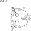
FIG. 2 is a diagram showing a configuration of guide plates included in the cutting device according to the first illustrative embodiment; -
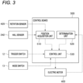
FIG. 3 is a diagram showing a configuration of a control board included in the cutting device according to the first illustrative embodiment; -
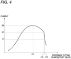
FIG. 4 is a diagram for illustrating a method of determining whether cutting is completed; -
FIG. 5A, FIG. 5B, and FIG. 5C are diagrams for illustrating an operation of cutting blades according to a state of a trigger switch in the first illustrative embodiment; -
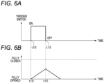
FIG. 6A and FIG. 6B are diagrams for illustrating an operation of the cutting blades according to the state of the trigger switch in the first illustrative embodiment; -
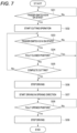
FIG. 7 is a flowchart showing a flow of processing executed by the control board; -
FIG. 8 is a flowchart showing a flow of processing executed by the control board; -
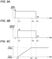
FIG. 9A, FIG. 9B, and FIG. 9C are diagrams for illustrating an operation of cutting blades according to a state of a trigger switch and the like in a second illustrative embodiment; and -
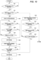
FIG. 10 is a flowchart showing a flow of processing executed by the control board. - The present illustrative embodiment will be described below with reference to the accompanying drawings. In order to facilitate understanding of the description, the same components are denoted by the same reference numerals as much as possible in the drawings, and redundant descriptions will be omitted.
- A first illustrative embodiment will be described. A
cutting device 10 according to the present illustrative embodiment is an electric cutting device, and is configured as a device for cutting a reinforcing bar at a construction site or the like. A configuration of thecutting device 10 will be described mainly with reference toFIG. 1 . Thecutting device 10 includes ahousing 11, atrigger switch 12, amode switch 13, acutting mechanism 100, aball screw 200, aspeed reducer 300, anelectric motor 400, acontrol board 500, and astorage battery 600. - The
housing 11 is a container that defines an outer shape of thecutting device 10. Thehousing 11 is made of resin, for example. Theball screw 200 described later, thespeed reducer 300 described later, and the like are housed inside thehousing 11. InFIG. 1 , a portion of thehousing 11 on a front side when viewed on paper is removed, and an internal configuration of thecutting device 10 is shown as a cross-sectional view. - The
trigger switch 12 is a switch operated by a finger of a user. The user can turn on thetrigger switch 12 by placing his or her finger on thetrigger switch 12 and pulling thetrigger switch 12 to the front side. When the user loosens his or her finger, the trigger switch 12 returns to an original position due to a force of a spring, and enters into the OFF state. When thetrigger switch 12 is switched between an ON state and the OFF state, a corresponding signal is transmitted to thecontrol board 500 described later. As will be described later, when thetrigger switch 12 is turned on by an operation of the user, an operation for cutting a reinforcing bar is started. Thetrigger switch 12 is one of "operation units" that can be switched between the ON state and the OFF state by the operation performed by the user. Thetrigger switch 12 corresponds to a "first operation unit" in the present illustrative embodiment. - The
mode switch 13 is a switch operated by the finger of the user, similar to thetrigger switch 12 described above. Themode switch 13 is provided at a position different from thetrigger switch 12, specifically, at a position in thehousing 11 near thestorage battery 600. The user can turn on themode switch 13 by pushing themode switch 13 toward the back with the finger. When the user releases his or her finger, themode switch 13 returns to an original position thereof due to the force of the spring, and enters into the OFF state. When themode switch 13 is switched between the ON state and the OFF state, a corresponding signal is transmitted to thecontrol board 500 described later. Themode switch 13 is one of the "operation units" that can be switched between the ON state and the OFF state by the operation performed by the user, and corresponds to a "second operation unit" in the present illustrative embodiment. - The
mode switch 13 is a part operated by the user when shifting the cuttingdevice 10 to a mode different from a normal mode, such as a mode for adjusting an accuracy of cuttingblades 111 in a standby state. Regarding a type of a mode that can be shifted to by the second operation unit, a method of an operation performed on themode switch 13, and the like, various known aspects can be adopted. - The
cutting mechanism 100 is a portion configured to cut the reinforcing bar which is an object to be cut. Thecutting mechanism 100 includes a pair ofblade members 110 and a pair oflink members 120. - The
cutting blades 111 that clamp and cut the object to be cut are formed on therespective blade members 110. Theblade member 110 is held pivotably about ashaft 101 fixed to thehousing 11. In the present illustrative embodiment, therespective blade members 110 are arranged to face each other such that ridge lines of blade edges of thecutting blades 111 operate on trajectories passing through substantially the same plane. Accordingly, it is possible to switch between an opened state where therespective cutting blades 111 are spaced apart from each other and a closed state where therespective cutting blades 111 come into contact with (or close to) each other. In the example ofFIG. 1 , the pair of cuttingblades 111 are in the closed state. - Each
link member 120 is a rod-shaped member, and one end of thelink member 120 is connected to theblade member 110 via ashaft 102, and the other end of thelink member 120 is connected to aconnection member 230 described later via ashaft 231. Thelink member 120 and theblade member 110 are connected to each other in a manner of pivoting about theshaft 102. Similarly, thelink member 120 and theconnection member 230 are connected to each other in a manner of pivoting about theshaft 231. As will be described later, theconnection member 230 moves in a left-right direction inFIG. 1 by a driving force of theelectric motor 400. - If the
connection member 230 moves in the left direction from the state shown inFIG. 1 , theblade member 110 on an upper side ofFIG. 1 pivots counterclockwise, and theblade member 110 on a lower side ofFIG. 1 pivots clockwise. Accordingly, the pair of cuttingblades 111 change from the closed state to the opened state. On the other hand, when the pair of cuttingblades 111 are in the opened state, if theconnection member 230 moves in the right direction inFIG. 1 , theblade member 110 on the upper side ofFIG. 1 pivots clockwise, and theblade member 110 on the lower side ofFIG. 1 pivots counterclockwise. Accordingly, the pair of cuttingblades 111 return to the closed state. As such, the pair ofblade members 110, the pair oflink members 120, and theconnection member 230 as a whole configure a so-called "toggle link mechanism". - In the present illustrative embodiment, a pair of
guide plates 700 are provided near theblade members 110. Theguide plates 700 are plate-shaped members made of metal, and are disposed to sandwich theblade members 110 from both the front side and the back side inFIG. 1 when viewed on paper. Shapes of the pair ofguide plates 700 are substantially the same. As shown inFIG. 2 , eachguide plate 700 has arecess 710 formed therein. - For convenience of description, a right side in
FIG. 1 will also be referred to as a "front end side" below, and a left side inFIG. 1 will be referred to as a "rear end side" below. Therecess 710 is formed to recede from the front end side toward the rear end side of theguide plate 700. When the cuttingdevice 10 is viewed from a side as shown inFIGS. 1 and2 , eachrecess 710 is formed at a position that includes thecutting blade 111 in the closed state. In the standby state where thecutting blades 111 are fully opened, thecutting blades 111 are retracted to the outside of therecesses 710, and from a perspective ofFIG. 2 , theentire blade members 110 are hidden by theguide plates 700. Theguide plates 700 have both a function of covering and protecting thecutting blades 111 in the standby state, and a function of guiding the reinforcing bar, which is the object to be cut, along therecesses 710 between the pair of cuttingblades 111. Theguide plates 700 further have a function of stabling a posture of the cuttingdevice 10 before and after cutting by sandwiching the reinforcing bar in therecesses 710. - The
ball screw 200 is configured to convert a rotational movement of theelectric motor 400 into a linear movement of theconnection member 230, thereby causing thecutting mechanism 100 to operate. Theball screw 200 includes ascrew shaft 210, anut 220, and theconnection member 230. - The
screw shaft 210 is a rod-shaped member that extends linearly from the rear end side to the front end side. A male screw is formed on an outer peripheral surface of thescrew shaft 210. When theelectric motor 400 is driven, thescrew shaft 210 rotates about a central axis thereof. - The
nut 220 is a substantially cylindrical member disposed to surround thescrew shaft 210 from an outer peripheral side. A female screw is formed on an inner peripheral surface of thenut 220, and is screwed to the male screw formed on the outer peripheral surface of thescrew shaft 210. While thenut 220 is allowed to move along a longitudinal direction of thescrew shaft 210, rotation about the central axis of thescrew shaft 210 is restricted. Therefore, when thescrew shaft 210 rotates about the central axis thereof, thenut 220 moves in the left-right direction inFIG. 1 along the central axis. - The
connection member 230 is attached to thenut 220 and is movable along thescrew shaft 210 together with thenut 220. Theconnection member 230 is attached in a manner of protruding from thenut 220 toward the front end side. The pair oflink members 120 are connected to a portion of theconnection member 230 near an end on the front end side via theshaft 231 described above. - A
magnet 241 is attached to the outer peripheral surface of theconnection member 230. AHall sensor 242 is attached to thehousing 11 at a position near theconnection member 230. The position where theHall sensor 242 is attached is such that when thenut 220 moves to a rear end from the state shown inFIG. 1 and thecutting blades 111 are fully opened, theHall sensor 242 faces themagnet 241 of theconnection member 230. When thecutting blades 111 are fully opened, a signal is transmitted from theHall sensor 242 by facing themagnet 241, and the signal is input to thecontrol board 500. - The
speed reducer 300 is a device that is configured to reduce a rotation speed of anoutput shaft 410 of theelectric motor 400 and then transmit the rotation to thescrew shaft 210 of theball screw 200. - The
electric motor 400 is a rotating electrical machine for generating a driving force necessary for operating thecutting blades 111, and is, for example, a brushless DC motor. Theelectric motor 400 has theoutput shaft 410. Theoutput shaft 410 is a substantially cylindrical member. A central axis of theoutput shaft 410 coincides with the central axis of thescrew shaft 210. A part of theoutput shaft 410 protrudes toward thespeed reducer 300 and is connected to thespeed reducer 300. - When current is supplied to a coil of the
electric motor 400, theoutput shaft 410 rotates about the central axis thereof. The rotation of theoutput shaft 410 is transmitted to thescrew shaft 210 via thespeed reducer 300, and causes thenut 220 to move toward the front end side or the rear end side. Accordingly, thecutting blades 111 of thecutting mechanism 100 are operated to open and close as described above. - A
rotation sensor 420 is provided inside theelectric motor 400. Therotation sensor 420 is configured to emit a pulse signal every time theoutput shaft 410 rotates by a predetermined angle. Therotation sensor 420 is provided on aboard 430 included in theelectric motor 400. The pulse signal from therotation sensor 420 is transmitted to thecontrol board 500. By counting the number of pulse signals, thecontrol board 500 is able to know a rotation angle of theoutput shaft 410 after a specific timing. Thecontrol board 500 is also able to know the rotation speed of theoutput shaft 410 based on the number of pulse signals input per unit time. Therotation sensor 420 may be a different type of a sensor from that of the present illustrative embodiment, or may be a sensor separately provided at a position different from theelectric motor 400 as long as the sensor can measure the rotation angle and the rotation speed of theoutput shaft 410. - The
control board 500 is a circuit board provided to control an overall operation of the cuttingdevice 10 including theelectric motor 400. Thecontrol board 500 includes an inverter circuit configured to adjust current supplied to theelectric motor 400, a microcomputer configured to control a switching operation and the like in the inverter circuit, and the like. - The
storage battery 600 stores electric power necessary for operating theelectric motor 400 and thecontrol board 500, and is, for example, a lithium ion battery. In thecutting device 10, a portion in which thestorage battery 600 is built is detachable from thehousing 11 as a battery pack, and is connected to and charged by an external charger. Instead of such an aspect, a configuration may be adopted in which thestorage battery 600 can be charged while thestorage battery 600 is attached to thehousing 11. - A configuration of the
control board 500 will be described with reference toFIG. 3 . Thecontrol board 500 having the microcomputer includes aposition acquisition unit 510, adetermination unit 520, and acontrol unit 530 as elements representing functions of thecontrol board 500. - The
position acquisition unit 510 is configured to perform processing of acquiring a current position of thecutting blades 111. In the present illustrative embodiment, a count value of the pulse signal input from therotation sensor 420 is calculated and acquired by theposition acquisition unit 510 as the "current position" of thecutting blades 111, based on a time when themagnet 241 and theHall sensor 242 face each other. The "current position" acquired by theposition acquisition unit 510 may be any index that directly or indirectly indicates the current position of thecutting blades 111, and may be a value other than the count value of the pulse signal. For example, when the angle between the pair of cuttingblades 111 is set as θ, a value of θ may be used as the above "current position". - In order to enable acquisition of the current position of the
cutting blades 111, a reset operation may be performed when the cuttingdevice 10 is started up. In the reset operation, for example, theelectric motor 400 may be driven in a direction where the pair of cuttingblades 111 change from the closed state to the opened state, and theelectric motor 400 may be stopped at a time point when a detection signal from theHall sensor 242 is input. By starting counting the pulse signals from this time point, the current position of thecutting blades 111 can be accurately acquired from then on. - The
determination unit 520 is configured to perform processing of determining whether the cutting of the object to be cut by thecutting blades 111 is completed. A method of this determination performed by thedetermination unit 520 will be described with reference toFIG. 4. FIG. 4 shows a relationship between the current position of thecutting blades 111, that is, the above count value (horizontal axis), and a value of current supplied to the electric motor 400 (vertical axis). Thedetermination unit 520 according to the present illustrative embodiment constantly monitors the value of current supplied to theelectric motor 400, and determines whether the cutting of the object to be cut is completed based on a change in the value of current. The value of current supplied to theelectric motor 400 may be measured by, for example, a current sensor (not shown) built into theelectric motor 400. The current sensor may be provided outside theelectric motor 400. - When the
electric motor 400 causes thecutting blades 111 to operate in a closing direction to cut the reinforcing bar, the value of current gradually increases in accordance with the resistance from the reinforcing bar. When plastic deformation of the reinforcing bar progresses and a yield point is reached, the value of current reaches a maximum, and thereafter the value of current gradually decreases. InFIG. 4 , the count value at a time point when the yield point is reached is shown as "C1", and the value of current at that time is shown as "IM". - When the
cutting blades 111 are further operated in the closing direction, in many cases, the reinforcing bar breaks before thecutting blades 111 reach the fully closed position. If the reinforcing bar breaks, the value of current also drops rapidly as the load drops. InFIG. 4 , the count value at a time point when the reinforcing bar breaks is shown as "C2", and the value of current at that time is shown as "IC". - "IT" shown in
FIG. 4 represents the value of current which is 50% of a maximum value (IM) at the yield point. "C3" shown inFIG. 4 represents the count value at a timing when the value of current decreases to IT. The value of current (IT), which is 50% of the maximum value (IM) at the yield point, is a value set in advance through experiments and the like as a value of current which is reliably lower than the value of current (IC) at which the reinforcing bar breaks. The value of 50% may be changed as appropriate. For example, the value of current (IT) may be set in a range of from 45% or more to 80 % or less of the maximum value (IM) at the yield point. - The
determination unit 520 determines that the cutting of the object to be cut by thecutting blades 111 is completed, that is, the reinforcing bar breaks when the value of current of theelectric motor 400 decreases to IT set as described above or lower. That is, IT is used as a threshold for determining whether the cutting of the object to be cut is completed. - As described above, the
determination unit 520 is configured to determine that the cutting of the object to be cut by thecutting blades 111 is completed when current supplied to theelectric motor 400 decreases by a predetermined percentage (50% in the present illustrative embodiment) from a maximum value thereof. - As the method of determination performed by the
determination unit 520, methods other than those described above may be used. For example, the number of rotations of theelectric motor 400 suddenly increases at the timing when the reinforcing bar breaks. Therefore, thedetermination unit 520 may determine that the cutting is completed at the timing when the number of rotations of theelectric motor 400 exceeds a predetermined threshold, or when a rate of change in the number of rotations exceeds a predetermined threshold. - Returning to
FIG. 3 , the description will be continued. Thecontrol unit 530 is configured to control the operation of theelectric motor 400. Thecontrol unit 530 controls an opening and closing operation of thecutting blades 111 by adjusting magnitude of current supplied to theelectric motor 400, for example, by PWM control. Thecontrol unit 530 also controls a braking operation of thecutting blades 111 by performing a so-called "short braking" that short-circuits some of a plurality of coils included in theelectric motor 400 periodically or continuously. - An overview of processing executed by the
control board 500 will be described with reference toFIGS. 5A, 5B, 5C ,6A, and 6B .FIG. 5A shows an example of a temporal change in a state of thetrigger switch 12. In this example, thetrigger switch 12 is turned on at a time t10, and then turned off at a time t22. -
FIG. 5B shows an example of a change in the position of thecutting blades 111 when thetrigger switch 12 is operated as described above. In this example, thecutting blades 111 are operated in a state where no reinforcing bar is present between the cuttingblades 111. When thetrigger switch 12 is turned on at the time t10, thecutting blades 111 move from the fully opened position to the fully closed position at a substantially constant speed. In the example ofFIG. 5B , thecutting blades 111 reach the fully closed position at a time t21 which is before the time t22. Although thetrigger switch 12 continues to be in the ON state, after the time t21, thecutting blades 111 automatically moves in an opposite direction and returns to the original fully opened position. No matter at what timing after the time t21 thetrigger switch 12 is returned to the OFF state, the operation of thecutting blades 111 as described above does not change. -
FIG. 5C shows an example of a change in the position of thecutting blades 111 when thetrigger switch 12 is operated as shown inFIG. 5A in a state where the reinforcing bar is inserted between the cuttingblades 111. In this example, before thecutting blades 111 reach the fully closed position, thedetermination unit 520 determines that the cutting of the reinforcing bar is completed at a time t20. In this case, thecutting blades 111 stop operating at the time t20, and thereafter return to the fully opened position. No matter what timing after the time t20 thetrigger switch 12 is returned to the OFF state, the operation of thecutting blades 111 as described above does not change. - As described above, after the
trigger switch 12 enters into the ON state and the pair of cuttingblades 111 start to operate in the closing direction, if thecutting blades 111 reach a predetermined position (in this example, the fully closed position) with thetrigger switch 12 in the ON state, thecontrol unit 530 starts the operation of opening the pair of cuttingblades 111. Thecontrol unit 530 starts the operation of opening the pair of cuttingblades 111 even when the cutting of the reinforcing bar is completed while thetrigger switch 12 is in the ON state. -
FIG. 6A shows an example of a temporal change in the state of thetrigger switch 12. In this example, thetrigger switch 12 is turned on at a time t10, and then turned off at a time t15. The time t15 is earlier than the time t20 in the example ofFIG. 5C . -
FIG. 6B shows an example of a change in the position of thecutting blades 111 when thetrigger switch 12 is operated as described above. In this example, after thecutting blades 111 start operating toward the fully closed position, thetrigger switch 12 is returned to the OFF state at the timing (time t15) before reaching the fully closed position. In this case, thecutting blades 111 stop operating at the time t15, and thereafter operate toward the fully opened position. Thecutting blades 111 stop operating at a time point when thecutting blades 111 return to the original fully opened position thereof. - As described above, after the
trigger switch 12 enters into the ON state and the pair of cuttingblades 111 start to operate in the closing direction, if thetrigger switch 12 changes from the ON state to the OFF state at a timing before the cutting of the reinforcing bar is completed, thecontrol unit 530 stops the operation of closing thecutting blades 111 and then starts the operation of opening thecutting blades 111. - Specifically, the description "timing before the cutting of the reinforcing bar is completed" in the above is a timing before the
cutting blades 111 reach the predetermined position (in this example, the fully closed position) and a timing before the cutting of the reinforcing bar is completed. - At a time point before the cutting of the reinforcing bar is completed or before the
cutting blades 111 reach the fully closed position, the user can return thetrigger switch 12 to the OFF state to immediately stop thecutting blades 111 that are operating in the closing direction. Therefore, it is possible to prevent situations such as accidentally cutting something other than the reinforcing bar. - A specific flow of processing executed by the
control board 500 will be described. A series of processing shown in a flowchart ofFIG. 7 is started by and performed by thecontrol board 500 when the cuttingdevice 10 is in a standby state, that is, when thecutting blades 111 are in the opened state. - In a first step S01, it is determined by the
control board 500, for example, whether thetrigger switch 12 is in the ON state. If thetrigger switch 12 is kept in the OFF state, the processing in step S01 is executed again and the standby state is maintained. If thetrigger switch 12 enters into the ON state, the processing proceeds to step S02. - In step S02, the
control unit 530 performs processing of driving theelectric motor 400 to start operating thecutting blades 111 in the closing direction. - In step S03 following step S02, it is determined again by the
control board 500, for example, whether thetrigger switch 12 is in the ON state. If thetrigger switch 12 is kept in the ON state, the processing proceeds to step S04. In step S04, it is determined by thecontrol board 500, for example, whether thecutting blades 111 reach the fully closed position. In the present illustrative embodiment, the position where the pair of cuttingblades 111 come into contact with each other is set as the "fully closed position", but the position immediately before the pair of cuttingblades 111 come into contact with each other may be set as the "fully closed position". - If the
cutting blades 111 do not reach the fully closed position, the processing proceeds to step S05. In step S05, thedetermination unit 520 performs processing of determining whether the cutting by thecutting blades 111 is completed, that is, whether the reinforcing bar breaks. The method of determination is as already described with reference toFIG. 4 . A specific processing flow for the determination will be described later with reference toFIG. 8 . - In step S05, if the cutting by the
cutting blades 111 is not completed, the processing in and after step S03 is executed again while continuing the operation of thecutting blades 111 toward the fully closed position. - If the
trigger switch 12 is returned to the OFF state in step S03, the processing proceeds to step S06. If thecutting blades 111 reach the fully closed position in step S04 or if it is determined that the cutting is completed in step S05, the processing also proceeds to step S06. In step S06, processing of stopping the operation of thecutting blades 111 is performed. Specifically, processing such as a short braking for braking thecutting blades 111 is started. In step S06, thecutting blades 111 may be stopped by simply stopping current supplied to theelectric motor 400. - Even after the processing in step S06 is started, the
cutting blades 111 continue to advance in the closing direction by a braking distance. In consideration of this point, in step S04, the determination of Yes may be made at a time point when thecutting blades 111 reach a position that is closer than the fully closed position by the braking distance. The braking distance in that case may be changed each time depending on the operation speed of thecutting blades 111 at that time point. - By performing the processing described above, in a period before the
cutting blades 111 reach the fully closed position and before the cutting of the reinforcing bar is completed, if thetrigger switch 12 enters into the OFF state, the processing immediately proceeds to step S06 to stop thecutting blades 111. - In step S07 following step S06, the
control unit 530 performs the processing of driving theelectric motor 400 to start operating thecutting blades 111 in the opening direction. - In step S08 following step S07, it is determined by the
control board 500, for example, whether thecutting blades 111 reach the fully opened position. If thecutting blades 111 do not reach the fully opened position, the processing in step S08 is executed again while continuing the operation of thecutting blades 111 toward the fully opened position. If thecutting blades 111 reach the fully opened position, the processing proceeds to step S09. In step S09, similar to step S06, processing of stopping the operation of thecutting blades 111 is performed. - Even after the processing in step S09 is started, the
cutting blades 111 continue to advance in the opening direction by a braking distance. In consideration of this point, in step S08, the determination of Yes may be made at a time point when thecutting blades 111 reach a position that is closer than the fully opened position by the braking distance. The braking distance in that case may be changed each time depending on the operation speed of thecutting blades 111 at that time point. - By performing the processing as described above, in a period after the
cutting blades 111 reach the fully closed position or after the cutting of the reinforcing bar is completed, thecutting blades 111 automatically move to the fully opened position regardless of the state of thetrigger switch 12. - A specific flow of the processing performed in step S05 to determine whether the cutting by the
cutting blades 111 is completed will be described with reference toFIG. 8 . If the processing proceeds to step S05 inFIG. 7 , thedetermination unit 520 executes a series of processing shown inFIG. 8 . - In a first step S11 of the processing, it is determined whether a count value indicating the current position of the
cutting blades 111 is larger than or equal to a predetermined value. The "predetermined value" is set in advance to indicate the position of thecutting blades 111 at a timing after the value of current of theelectric motor 400 is stably detected. In the example ofFIG. 4 , the predetermined value is set at a position closer to the front side (on an opening direction side, a left side inFIG. 4 ) than C1 corresponding to the yield point. - If the count value is less than the predetermined value, the processing proceeds to step S16. In step S16, it is determined that the cutting by the
cutting blades 111 is not completed. Thereafter, the processing proceeds to step S03 from step S05 inFIG. 7 . - In step S11 of
FIG. 8 , if the count value is larger than or equal to the predetermined value, the processing proceeds to step S12. In step S12, it is determined whether the value of current currently supplied to theelectric motor 400 is larger than or equal to a maximum value of current. The "maximum value of current" is a variable for storing the maximum value of current supplied to theelectric motor 400, and is used to store IM ofFIG. 4 in advance. Before the processing ofFIG. 8 is started for the first time, the maximum value of current is reset to 0 in advance. The processing may be executed, for example, immediately before step S02 inFIG. 7 . - In step S12, if the current value of current is larger than or equal to the maximum value of current, the processing proceeds to step S13. In
step S 13, the maximum value of current is updated. Specifically, the current value of current is substituted for the maximum value of current. Then, the processing proceeds to step S14. In step S12, if the current value of current is less than the maximum value of current, the processing proceeds to step S14 without performing step S13. - In step S14, it is determined whether the current value of current is 50% or less of the maximum value of current. If the current value of current decreases to 50% or less of the maximum value of current, the processing proceeds to step S15. Proceeding to step S15 means that the value of current decreases to the value of current IT or less in the example of
FIG. 4 . Therefore, in this case, it is determined that the cutting by thecutting blades 111 is completed. Then, the processing proceeds to step S06 from step S05 inFIG. 7 . In step S14, if the current value of current exceeds 50% of maximum value of current, the processing proceeds to step S16. As described above, in step S16, it is determined that the cutting by thecutting blades 111 is not completed. - As described above, the
determination unit 520 according to the present illustrative embodiment determines whether the cutting of the reinforcing bar by thecutting blades 111 is completed based on current supplied to theelectric motor 400. Accordingly, the determination in step S05 inFIG. 7 can be made accurately, and thecutting blades 111 can be returned to the opened state at an appropriate timing. - A second illustrative embodiment is described. In the following, points different from the first illustrative embodiment will be mainly described, and descriptions of points common to those of the first illustrative embodiment will be omitted as appropriate. The present illustrative embodiment differs from the first illustrative embodiment in contents of the processing executed by the
control board 500. - In the present illustrative embodiment, similar to the first illustrative embodiment described above, the
cutting blades 111 are also automatically returned to the opened state when the cutting is completed. Even if thetrigger switch 12 is turned off before the cutting is completed, thecutting blades 111 are automatically returned to the opened state. In such a configuration, when the operation of the cuttingdevice 10 is stopped, thecutting blades 111 are always kept in the opened state. However, when the cuttingdevice 10 is not operated for a long time, thecutting blades 111 may preferably be kept in the closed state for safety reasons. - Therefore, in the
cutting device 10 according to the present illustrative embodiment, thecutting blades 111 can be kept in the closed state in advance by the user performing a specific operation. -
FIG. 9B shows an example of a temporal change in the state of thetrigger switch 12. The operation performed on thetrigger switch 12 in this example is the same as the operation performed in the example ofFIG. 5A .FIG. 9A shows an example of a temporal change in a state of themode switch 13. In this example, themode switch 13 is turned on at a time t1, which is before a time t10, and is turned off at a time t22. -
FIG. 9C shows an example of a change in the position of thecutting blades 111 when thetrigger switch 12 and themode switch 13 are operated as described above. When thetrigger switch 12 is turned on at the time t10, similar to the previous examples, thecutting blades 111 start to move in the closing direction. However, if both thetrigger switch 12 and themode switch 13 are kept in the ON state, thecutting blades 111 remain stopped after reaching the fully closed position and do not automatically return to the fully opened position. Then, even when thetrigger switch 12 and themode switch 13 return to the OFF state, thecutting blades 111 remain stopped at the fully closed position. - Accordingly, if both the trigger switch 12 (first operation unit) and the mode switch 13 (second operation unit) are in the ON state, the
control unit 530 of the cuttingdevice 10 according to the present illustrative embodiment performs control to keep thecutting blades 111 in the closed state after performing an operation of closing the pair of cuttingblades 111. This control will be referred to as "closed-keep control" below. - If the
mode switch 13 is kept in the OFF state and only thetrigger switch 12 is turned on, thecontrol unit 530 performs normal control similar to that described in the first illustrative embodiment, that is, control that causes the pair of cuttingblades 111 to close and then opens thecutting blades 111. - A specific flow of processing executed by the
control board 500 according to the present illustrative embodiment will be described with reference toFIG. 10 . A series of processing shown inFIG. 10 is executed by thecontrol board 500 according to the present illustrative embodiment instead of the series of the processing shown inFIG. 7 . Among steps shown inFIG. 10 , the steps common to those shown inFIG. 7 are given the same reference numerals (such as "S01") as inFIG. 7 . A flowchart inFIG. 10 is obtained by adding processing of steps S21 to S25 to the flowchart inFIG. 7 . - In step S01, when it is determined by the
control board 500, for example, that thetrigger switch 12 enters into the ON state, the processing proceeds to step S21 in the present illustrative embodiment. In step S21, it is determined by thecontrol board 500, for example, whether themode switch 13 is in the ON state. If themode switch 13 is kept in the OFF state, the processing in and after step S02 is executed, and normal control similar to that in the first illustrative embodiment is executed. If themode switch 13 is in the ON state, the processing proceeds to step S22. - In step S22, the
control unit 530 performs processing of driving theelectric motor 400 to start operating thecutting blades 111 in the closing direction. Accordingly, the closed-keep control is started. - In step S23 following step S22, it is determined by the
control board 500, for example, whether thetrigger switch 12 is in the ON state. If thetrigger switch 12 is kept in the ON state, the processing proceeds to step S24. - In step S24, it is determined by the
control board 500, for example, whether themode switch 13 is in the ON state. If themode switch 13 is kept in the ON state, the processing proceeds to step S25. - In step S25, it is determined by the
control board 500, for example, whether thecutting blades 111 reach the fully closed position. The processing performed here is the same as the processing performed in step S04. If thecutting blades 111 do not reach the fully closed position, the processing in and after step S23 is executed again while continuing the operation of thecutting blades 111 toward the fully closed position. If thecutting blades 111 reach the fully closed position, the processing proceeds to step S09. Accordingly, the closed-keep control is completed, and thecutting blades 111 remain stopped at the fully closed position. - If the
trigger switch 12 is turned off in step S23 or if themode switch 13 is turned off in step S24 while the closed-keep control is being executed, the processing proceeds to step S06. As a result, the closed-keep control is interrupted and thecutting blades 111 are returned to the fully opened position. The cuttingdevice 10 returns to the standby state under the normal control. - As described above, after starting the closed-keep control in step S22, if at least one of the trigger switch 12 (first operation unit) and the mode switch 13 (second operation unit) enters into the OFF state at a timing before the operation of closing the pair of cutting
blades 111 is completed (if it is determined No in step S23 or S24), thecontrol unit 530 of the cuttingdevice 10 according to the present illustrative embodiment stops the operation of closing the cutting blades 111 (step S06). Then, thecontrol unit 530 starts the operation of opening the cutting blades 111 (step S07), and returns the cuttingblades 111 to the fully opened position. Accordingly, the user can easily interrupt the closed-keep control and restart the work. - The present illustrative embodiment has been described above with reference to specific examples. However, the present disclosure is not limited to these specific examples. Design changes made by those skilled in the art as appropriate to these specific examples are also included within the scope of the present disclosure as long as the changes have characteristics of the present disclosure. Elements included in each of the specific examples described above, and arrangement, conditions, shapes, and the like of the elements are not limited to those illustrated, and can be changed as appropriate. The elements included in each of the specific examples described above can be appropriately combined as long as no technical contradiction occurs.
Claims (10)
- An electric cutting device, comprising:a pair of cutting blades configured to clamp and cut an object;an electric motor configured to generate a driving force necessary for operating the cutting blades;a control unit configured to control an operation of the electric motor;an operation unit configured to be switched between an ON state and an OFF state by a user operation; anda determination unit configured to determine whether cutting of the object by the cutting blades is completed,wherein after the operation unit enters into the ON state and the pair of cutting blades start operating in a closing direction, the control unit is configured to:start an operation of opening the pair of cutting blades in a case where the cutting of the object is completed while the operation unit is kept in the ON state; andstop an operation of closing the pair of cutting blades in a case where the operation unit changes from the ON state to the OFF state at a timing before the cutting of the object is completed.
- The cutting device according to claim 1, wherein the control unit is configured to:
start the operation of opening the pair of cutting blades after the operation unit changes from the ON state to the OFF state and the operation of closing the pair of cutting blades is stopped. - The cutting device according to claim 1, wherein the determination unit is configured to perform the determination based on current supplied to the electric motor.
- The cutting device according to claim 3, wherein the determination unit determines that the cutting of the object by the cutting blades is completed in a case where the current supplied to the electric motor decreases by a predetermined percentage from a maximum value of current.
- The cutting device according to claim 1, wherein the determination unit is configured to perform the determination based on the number of rotations of the electric motor.
- The cutting device according to claim 1, wherein the control unit is configured to:
start the operation of opening the pair of cutting blades even if the cutting blades reach a predetermined position while the operation unit is kept in the ON state. - The cutting device according to claim 6, wherein the control unit is configured to:
stop the operation of closing the pair of cutting blades in a case where the operation unit changes from the ON state to the OFF state at a timing before the cutting blades reach the predetermined position and before the cutting of the object is completed. - The cutting device according to claim 1,wherein the operation unit includes a first operation unit and a second operation unit provided at different positions, andwherein the control unit is configured to:in a case where only the first operation unit enters into the ON state,
perform normal control to perform the operation of opening the pair of cutting blades after performing the operation of closing the pair of cutting blades, andin a case where both the first operation unit and the second operation unit enter into the ON state,
perform closed-keep control to maintain the pair of cutting blades in a closed state after performing the operation of closing the pair of cutting blades. - The cutting device according to claim 8, wherein the control unit is configured to:
stop the operation of closing the pair of cutting blades in a case where at least one of the first operation unit and the second operation unit enters into the OFF state at a timing after starting the closed-keep control and before the operation of closing the pair of cutting blades is completed. - The cutting device according to claim 9, wherein the control unit is configured to:
start the operation of opening the pair of cutting blades after at least one of the first operation unit and the second operation unit enters into the OFF state and the operation of closing the pair of cutting blades is stopped.
Applications Claiming Priority (8)
| Application Number | Priority Date | Filing Date | Title |
|---|---|---|---|
| JP2022210638 | 2022-12-27 | ||
| JP2022210372A JP2024093790A (en) | 2022-12-27 | 2022-12-27 | Cutting device |
| JP2022210594A JP2024093934A (en) | 2022-12-27 | 2022-12-27 | Cutting device |
| JP2022210362A JP2024093782A (en) | 2022-12-27 | 2022-12-27 | Cutting device |
| JP2022210196A JP7905039B2 (en) | 2022-12-27 | 2022-12-27 | cutting device |
| JP2022210308A JP2024093744A (en) | 2022-12-27 | 2022-12-27 | Cutting device |
| JP2022210302A JP2024093739A (en) | 2022-12-27 | 2022-12-27 | Cutting device |
| JP2022210296A JP2024093736A (en) | 2022-12-27 | 2022-12-27 | Cutting device |
Publications (2)
| Publication Number | Publication Date |
|---|---|
| EP4397458A1 true EP4397458A1 (en) | 2024-07-10 |
| EP4397458B1 EP4397458B1 (en) | 2026-07-01 |
Family
ID=89385883
Family Applications (7)
| Application Number | Title | Priority Date | Filing Date |
|---|---|---|---|
| EP23220295.2A Pending EP4393666A1 (en) | 2022-12-27 | 2023-12-27 | Cutting device |
| EP23220271.3A Pending EP4393663A1 (en) | 2022-12-27 | 2023-12-27 | Cutting device |
| EP23220289.5A Active EP4397458B1 (en) | 2022-12-27 | 2023-12-27 | CUTTING DEVICE |
| EP23220296.0A Pending EP4403322A3 (en) | 2022-12-27 | 2023-12-27 | Cutting device |
| EP23220293.7A Pending EP4403321A1 (en) | 2022-12-27 | 2023-12-27 | Cutting device |
| EP23220287.9A Pending EP4393664A1 (en) | 2022-12-27 | 2023-12-27 | Cutting device |
| EP23220290.3A Pending EP4393665A1 (en) | 2022-12-27 | 2023-12-27 | Cutting device |
Family Applications Before (2)
| Application Number | Title | Priority Date | Filing Date |
|---|---|---|---|
| EP23220295.2A Pending EP4393666A1 (en) | 2022-12-27 | 2023-12-27 | Cutting device |
| EP23220271.3A Pending EP4393663A1 (en) | 2022-12-27 | 2023-12-27 | Cutting device |
Family Applications After (4)
| Application Number | Title | Priority Date | Filing Date |
|---|---|---|---|
| EP23220296.0A Pending EP4403322A3 (en) | 2022-12-27 | 2023-12-27 | Cutting device |
| EP23220293.7A Pending EP4403321A1 (en) | 2022-12-27 | 2023-12-27 | Cutting device |
| EP23220287.9A Pending EP4393664A1 (en) | 2022-12-27 | 2023-12-27 | Cutting device |
| EP23220290.3A Pending EP4393665A1 (en) | 2022-12-27 | 2023-12-27 | Cutting device |
Country Status (6)
| Country | Link |
|---|---|
| US (7) | US20240208088A1 (en) |
| EP (7) | EP4393666A1 (en) |
| KR (4) | KR20240104041A (en) |
| AU (6) | AU2023285962B2 (en) |
| CA (4) | CA3224768A1 (en) |
| TW (4) | TW202440253A (en) |
Families Citing this family (2)
| Publication number | Priority date | Publication date | Assignee | Title |
|---|---|---|---|---|
| US20240300038A1 (en) * | 2023-03-09 | 2024-09-12 | Milwaukee Electric Tool Corporation | Powered tubing cutter |
| KR20260020745A (en) | 2024-08-05 | 2026-02-12 | 주식회사 엘지에너지솔루션 | Battery pack |
Citations (6)
| Publication number | Priority date | Publication date | Assignee | Title |
|---|---|---|---|---|
| US20110056082A1 (en) | 2009-09-08 | 2011-03-10 | Chervon Limited | Electric shears |
| US20130055575A1 (en) * | 2010-03-24 | 2013-03-07 | Infaco Sas | Device for controlling the relative positioning of two elements, such as the blades of secateur-type cutting tools, and a cutting tool comprising same |
| EP3466578A1 (en) * | 2016-05-24 | 2019-04-10 | Izumi Products Company | Power tool |
| US10799962B2 (en) * | 2016-12-09 | 2020-10-13 | Cembre S.P.A. | Working head for a compression or cutting tool |
| US20210339410A1 (en) * | 2020-04-30 | 2021-11-04 | Max Co., Ltd. | Electric scissors |
| US20220312680A1 (en) * | 2019-09-13 | 2022-10-06 | Ars Corporation | Electric-powered cutting device for pruning |
Family Cites Families (18)
| Publication number | Priority date | Publication date | Assignee | Title |
|---|---|---|---|---|
| US2529895A (en) * | 1948-05-06 | 1950-11-14 | George V Anderson | Electrical cutting and punching machine |
| US3688405A (en) * | 1971-04-21 | 1972-09-05 | Joseph G Dutra Jr | Pruning shears |
| US4369576A (en) * | 1981-05-22 | 1983-01-25 | Mcvaugh Arthur K | Hand-held cable cutter |
| US5235750A (en) | 1992-05-19 | 1993-08-17 | Brown Frank R | Hand tools |
| US6735870B2 (en) * | 2001-01-09 | 2004-05-18 | Greenlee Textron Inc. | Cutter for fiber optic cable and method of using same |
| ES1050293Y (en) * | 2001-10-25 | 2002-07-01 | Hispaes S A | MOTORIZED CUTTING TOOL WITH AUTOMATION CUTTING DEVICE. |
| JP2004305690A (en) * | 2003-02-18 | 2004-11-04 | Hasegawa Hamono Kk | Cap for scissors and scissors |
| ES2245217B1 (en) * | 2004-03-04 | 2006-08-01 | Josep Gurri Molins | MECHANICALLY OPERATED PORTABLE CUTTING TOOL. |
| ES2268954B1 (en) * | 2005-01-27 | 2008-03-01 | Josep Gurri Molins | PORTABLE MOTORIZED CUTTING TOOL. |
| EP2158803B1 (en) * | 2008-08-26 | 2011-04-27 | Robert Bosch GmbH | Vegetation cutting tool |
| US8327548B2 (en) * | 2009-02-23 | 2012-12-11 | Ronan John S | Utility cutter with a non-tool blade changer |
| CN103327806B (en) * | 2010-12-30 | 2016-01-13 | 创科户外产品技术有限公司 | electric pruning tool |
| JP5741252B2 (en) * | 2011-06-28 | 2015-07-01 | マックス株式会社 | Electric scissors |
| WO2014009363A1 (en) | 2012-07-10 | 2014-01-16 | Gustav Klauke Gmbh | Pressing tool |
| WO2019152439A1 (en) * | 2018-01-30 | 2019-08-08 | Milwaukee Electric Tool Corporation | Power tool |
| FI128867B (en) * | 2019-08-29 | 2021-02-15 | Tmi Linden Instr | An electric pole pruner |
| US12202155B2 (en) * | 2020-09-10 | 2025-01-21 | Techtronic Cordless Gp | Blade change mechanism for power tool |
| KR20240032642A (en) * | 2022-09-03 | 2024-03-12 | 둥관 코햄 인더스트리얼 컴퍼니 리미티드 | Signal generator based on inductance characteristics of element, electric shearing tool, and shear opening degree control method for electric shearing tool |
-
2023
- 2023-12-21 CA CA3224768A patent/CA3224768A1/en active Pending
- 2023-12-22 CA CA3224822A patent/CA3224822A1/en active Pending
- 2023-12-22 CA CA3224805A patent/CA3224805A1/en active Pending
- 2023-12-22 AU AU2023285962A patent/AU2023285962B2/en active Active
- 2023-12-22 AU AU2023285964A patent/AU2023285964B2/en active Active
- 2023-12-22 CA CA3224813A patent/CA3224813A1/en active Pending
- 2023-12-22 AU AU2023285963A patent/AU2023285963B2/en active Active
- 2023-12-22 AU AU2023285960A patent/AU2023285960B2/en active Active
- 2023-12-26 TW TW112150784A patent/TW202440253A/en unknown
- 2023-12-26 KR KR1020230191441A patent/KR20240104041A/en active Pending
- 2023-12-26 TW TW112150787A patent/TW202435744A/en unknown
- 2023-12-26 KR KR1020230191431A patent/KR20240104040A/en active Pending
- 2023-12-26 TW TW112150783A patent/TW202435743A/en unknown
- 2023-12-26 KR KR1020230191421A patent/KR20240104038A/en active Pending
- 2023-12-26 KR KR1020230191411A patent/KR20240104036A/en active Pending
- 2023-12-26 TW TW112150785A patent/TW202440254A/en unknown
- 2023-12-27 EP EP23220295.2A patent/EP4393666A1/en active Pending
- 2023-12-27 US US18/397,582 patent/US20240208088A1/en active Pending
- 2023-12-27 EP EP23220271.3A patent/EP4393663A1/en active Pending
- 2023-12-27 EP EP23220289.5A patent/EP4397458B1/en active Active
- 2023-12-27 US US18/397,502 patent/US20240207953A1/en active Pending
- 2023-12-27 EP EP23220296.0A patent/EP4403322A3/en active Pending
- 2023-12-27 US US18/397,730 patent/US12544942B2/en active Active
- 2023-12-27 US US18/397,697 patent/US12583135B2/en active Active
- 2023-12-27 EP EP23220293.7A patent/EP4403321A1/en active Pending
- 2023-12-27 US US18/397,763 patent/US20240208090A1/en active Pending
- 2023-12-27 EP EP23220287.9A patent/EP4393664A1/en active Pending
- 2023-12-27 US US18/397,608 patent/US12570014B2/en active Active
- 2023-12-27 EP EP23220290.3A patent/EP4393665A1/en active Pending
- 2023-12-27 US US18/397,796 patent/US12576546B2/en active Active
-
2026
- 2026-06-23 AU AU2026204813A patent/AU2026204813A1/en active Pending
- 2026-06-23 AU AU2026204841A patent/AU2026204841A1/en active Pending
Patent Citations (6)
| Publication number | Priority date | Publication date | Assignee | Title |
|---|---|---|---|---|
| US20110056082A1 (en) | 2009-09-08 | 2011-03-10 | Chervon Limited | Electric shears |
| US20130055575A1 (en) * | 2010-03-24 | 2013-03-07 | Infaco Sas | Device for controlling the relative positioning of two elements, such as the blades of secateur-type cutting tools, and a cutting tool comprising same |
| EP3466578A1 (en) * | 2016-05-24 | 2019-04-10 | Izumi Products Company | Power tool |
| US10799962B2 (en) * | 2016-12-09 | 2020-10-13 | Cembre S.P.A. | Working head for a compression or cutting tool |
| US20220312680A1 (en) * | 2019-09-13 | 2022-10-06 | Ars Corporation | Electric-powered cutting device for pruning |
| US20210339410A1 (en) * | 2020-04-30 | 2021-11-04 | Max Co., Ltd. | Electric scissors |
Also Published As
Similar Documents
| Publication | Publication Date | Title |
|---|---|---|
| US20240207955A1 (en) | Cutting device | |
| CN118253667A (en) | Cutting device | |
| JP2024093782A (en) | Cutting device | |
| JP2024093739A (en) | Cutting device | |
| JP2024093934A (en) | Cutting device | |
| US20240208089A1 (en) | Cutting device | |
| JP2024093736A (en) | Cutting device | |
| JP2024093790A (en) | Cutting device |
Legal Events
| Date | Code | Title | Description |
|---|---|---|---|
| PUAI | Public reference made under article 153(3) epc to a published international application that has entered the european phase |
Free format text: ORIGINAL CODE: 0009012 |
|
| STAA | Information on the status of an ep patent application or granted ep patent |
Free format text: STATUS: THE APPLICATION HAS BEEN PUBLISHED |
|
| AK | Designated contracting states |
Kind code of ref document: A1 Designated state(s): AL AT BE BG CH CY CZ DE DK EE ES FI FR GB GR HR HU IE IS IT LI LT LU LV MC ME MK MT NL NO PL PT RO RS SE SI SK SM TR |
|
| STAA | Information on the status of an ep patent application or granted ep patent |
Free format text: STATUS: REQUEST FOR EXAMINATION WAS MADE |
|
| 17P | Request for examination filed |
Effective date: 20250108 |
|
| GRAP | Despatch of communication of intention to grant a patent |
Free format text: ORIGINAL CODE: EPIDOSNIGR1 |
|
| STAA | Information on the status of an ep patent application or granted ep patent |
Free format text: STATUS: GRANT OF PATENT IS INTENDED |
|
| INTG | Intention to grant announced |
Effective date: 20260123 |
|
| GRAS | Grant fee paid |
Free format text: ORIGINAL CODE: EPIDOSNIGR3 |
|
| GRAA | (expected) grant |
Free format text: ORIGINAL CODE: 0009210 |
|
| STAA | Information on the status of an ep patent application or granted ep patent |
Free format text: STATUS: THE PATENT HAS BEEN GRANTED |
|
| AK | Designated contracting states |
Kind code of ref document: B1 Designated state(s): AL AT BE BG CH CY CZ DE DK EE ES FI FR GB GR HR HU IE IS IT LI LT LU LV MC ME MK MT NL NO PL PT RO RS SE SI SK SM TR |
|
| REG | Reference to a national code |
Ref country code: CH Ref legal event code: F10 Free format text: ST27 STATUS EVENT CODE: U-0-0-F10-F00 (AS PROVIDED BY THE NATIONAL OFFICE) Effective date: 20260701 Ref country code: GB Ref legal event code: FG4D |
|
| REG | Reference to a national code |
Ref country code: CH Ref legal event code: R17 Free format text: ST27 STATUS EVENT CODE: U-0-0-R10-R17 (AS PROVIDED BY THE NATIONAL OFFICE) Effective date: 20260703 |
|
| REG | Reference to a national code |
Ref country code: DE Ref legal event code: R096 Ref document number: 602023019175 Country of ref document: DE |
|
| REG | Reference to a national code |
Ref country code: IE Ref legal event code: FG4D |