EP4403322A2 - Cutting device - Google Patents
Cutting device Download PDFInfo
- Publication number
- EP4403322A2 EP4403322A2 EP23220296.0A EP23220296A EP4403322A2 EP 4403322 A2 EP4403322 A2 EP 4403322A2 EP 23220296 A EP23220296 A EP 23220296A EP 4403322 A2 EP4403322 A2 EP 4403322A2
- Authority
- EP
- European Patent Office
- Prior art keywords
- cutting
- cutting device
- predetermined direction
- guide plate
- along
- Prior art date
- Legal status (The legal status is an assumption and is not a legal conclusion. Google has not performed a legal analysis and makes no representation as to the accuracy of the status listed.)
- Pending
Links
- 230000008602 contraction Effects 0.000 claims description 4
- 230000003014 reinforcing effect Effects 0.000 description 24
- 230000002093 peripheral effect Effects 0.000 description 7
- 239000003638 chemical reducing agent Substances 0.000 description 6
- 238000010586 diagram Methods 0.000 description 6
- 238000010276 construction Methods 0.000 description 2
- HBBGRARXTFLTSG-UHFFFAOYSA-N Lithium ion Chemical compound [Li+] HBBGRARXTFLTSG-UHFFFAOYSA-N 0.000 description 1
- 238000001514 detection method Methods 0.000 description 1
- 230000000694 effects Effects 0.000 description 1
- 229910001416 lithium ion Inorganic materials 0.000 description 1
- 229910052751 metal Inorganic materials 0.000 description 1
- 239000002184 metal Substances 0.000 description 1
- 239000011347 resin Substances 0.000 description 1
- 229920005989 resin Polymers 0.000 description 1
- 230000000087 stabilizing effect Effects 0.000 description 1
Images


Classifications
-
- B—PERFORMING OPERATIONS; TRANSPORTING
- B23—MACHINE TOOLS; METAL-WORKING NOT OTHERWISE PROVIDED FOR
- B23D—PLANING; SLOTTING; SHEARING; BROACHING; SAWING; FILING; SCRAPING; LIKE OPERATIONS FOR WORKING METAL BY REMOVING MATERIAL, NOT OTHERWISE PROVIDED FOR
- B23D33/00—Accessories for shearing machines or shearing devices
- B23D33/02—Arrangements for holding, guiding, and/or feeding work during the operation
-
- B—PERFORMING OPERATIONS; TRANSPORTING
- B23—MACHINE TOOLS; METAL-WORKING NOT OTHERWISE PROVIDED FOR
- B23D—PLANING; SLOTTING; SHEARING; BROACHING; SAWING; FILING; SCRAPING; LIKE OPERATIONS FOR WORKING METAL BY REMOVING MATERIAL, NOT OTHERWISE PROVIDED FOR
- B23D29/00—Hand-held metal-shearing or metal-cutting devices
- B23D29/002—Hand-held metal-shearing or metal-cutting devices for cutting wire or the like
-
- B—PERFORMING OPERATIONS; TRANSPORTING
- B23—MACHINE TOOLS; METAL-WORKING NOT OTHERWISE PROVIDED FOR
- B23D—PLANING; SLOTTING; SHEARING; BROACHING; SAWING; FILING; SCRAPING; LIKE OPERATIONS FOR WORKING METAL BY REMOVING MATERIAL, NOT OTHERWISE PROVIDED FOR
- B23D36/00—Control arrangements specially adapted for machines for shearing or similar cutting, or for sawing, stock which the latter is travelling otherwise than in the direction of the cut
- B23D36/0008—Control arrangements specially adapted for machines for shearing or similar cutting, or for sawing, stock which the latter is travelling otherwise than in the direction of the cut for machines with only one cutting, sawing, or shearing devices
-
- B—PERFORMING OPERATIONS; TRANSPORTING
- B26—HAND CUTTING TOOLS; CUTTING; SEVERING
- B26B—HAND-HELD CUTTING TOOLS NOT OTHERWISE PROVIDED FOR
- B26B15/00—Hand-held shears with motor-driven blades
-
- B—PERFORMING OPERATIONS; TRANSPORTING
- B26—HAND CUTTING TOOLS; CUTTING; SEVERING
- B26B—HAND-HELD CUTTING TOOLS NOT OTHERWISE PROVIDED FOR
- B26B29/00—Guards or sheaths or guides for hand cutting tools; Arrangements for guiding hand cutting tools
- B26B29/04—Guards or sheaths for scissors, e.g. combined with manicuring appliances
-
- B—PERFORMING OPERATIONS; TRANSPORTING
- B26—HAND CUTTING TOOLS; CUTTING; SEVERING
- B26B—HAND-HELD CUTTING TOOLS NOT OTHERWISE PROVIDED FOR
- B26B29/00—Guards or sheaths or guides for hand cutting tools; Arrangements for guiding hand cutting tools
- B26B29/06—Arrangements for guiding hand cutting tools
-
- B—PERFORMING OPERATIONS; TRANSPORTING
- B26—HAND CUTTING TOOLS; CUTTING; SEVERING
- B26D—CUTTING; DETAILS COMMON TO MACHINES FOR PERFORATING, PUNCHING, CUTTING-OUT, STAMPING-OUT OR SEVERING
- B26D3/00—Cutting work characterised by the nature of the cut made; Apparatus therefor
- B26D3/16—Cutting rods or tubes transversely
- B26D3/169—Hand held tube cutters
-
- B—PERFORMING OPERATIONS; TRANSPORTING
- B26—HAND CUTTING TOOLS; CUTTING; SEVERING
- B26D—CUTTING; DETAILS COMMON TO MACHINES FOR PERFORATING, PUNCHING, CUTTING-OUT, STAMPING-OUT OR SEVERING
- B26D5/00—Arrangements for operating and controlling machines or devices for cutting, cutting-out, stamping-out, punching, perforating, or severing by means other than cutting
- B26D5/08—Means for actuating the cutting member to effect the cut
- B26D5/086—Electric, magnetic, piezoelectric, electro-magnetic means
-
- B—PERFORMING OPERATIONS; TRANSPORTING
- B26—HAND CUTTING TOOLS; CUTTING; SEVERING
- B26D—CUTTING; DETAILS COMMON TO MACHINES FOR PERFORATING, PUNCHING, CUTTING-OUT, STAMPING-OUT OR SEVERING
- B26D5/00—Arrangements for operating and controlling machines or devices for cutting, cutting-out, stamping-out, punching, perforating, or severing by means other than cutting
- B26D5/20—Arrangements for operating and controlling machines or devices for cutting, cutting-out, stamping-out, punching, perforating, or severing by means other than cutting with interrelated action between the cutting member and work feed
- B26D5/26—Arrangements for operating and controlling machines or devices for cutting, cutting-out, stamping-out, punching, perforating, or severing by means other than cutting with interrelated action between the cutting member and work feed wherein control means on the work feed means renders the cutting member operative
- B26D5/28—Arrangements for operating and controlling machines or devices for cutting, cutting-out, stamping-out, punching, perforating, or severing by means other than cutting with interrelated action between the cutting member and work feed wherein control means on the work feed means renders the cutting member operative the control means being responsive to presence or absence of work
-
- B—PERFORMING OPERATIONS; TRANSPORTING
- B23—MACHINE TOOLS; METAL-WORKING NOT OTHERWISE PROVIDED FOR
- B23D—PLANING; SLOTTING; SHEARING; BROACHING; SAWING; FILING; SCRAPING; LIKE OPERATIONS FOR WORKING METAL BY REMOVING MATERIAL, NOT OTHERWISE PROVIDED FOR
- B23D17/00—Shearing machines or shearing devices cutting by blades pivoted on a single axis
- B23D17/02—Shearing machines or shearing devices cutting by blades pivoted on a single axis characterised by drives or gearings therefor
- B23D17/04—Shearing machines or shearing devices cutting by blades pivoted on a single axis characterised by drives or gearings therefor actuated by a rotary shaft
Definitions
- the present disclosure relates to an electric cutting device.
- a cutting device as described in JP2021-171580A As an electric cutting device, a cutting device as described in JP2021-171580A is known, for example.
- cutting blades are operated by a driving force of an electric motor instead of a gripping force of a user, and clamp an object to be cut and cut the object with the pair of cutting blades.
- the cutting device described in JP2021-171580A is provided with a pair of guide plates so as to sandwich the cutting blades from the outside.
- the guide plate is formed with a recess for receiving the object to be cut in advance and guiding the object to be cut to a predetermined position during cutting. When cutting the object to be cut, the cutting blades are closed with the object to be cut placed at the predetermined position.
- Illustrative aspects of the present disclosure provide a cutting device that can cut an object to be cut near a wall or the like while protecting a cutting blade with a guide plate.
- An electric cutting device includes: a pair of cutting blades configured to clamp and cut an object by rotating about a rotation central axis; an electric motor configured to generate a driving force necessary for operating the cutting blades; and a guide plate having a recess in a manner of receding along a predetermined direction, the recess being for housing the object in advance when the object is cut by the pair of cutting blades.
- An edge of the recess includes a pair of linear portions that are parallel to each other and face each other with a predetermined interval.
- a distance between the first position and the second position along the predetermined direction is one-fourth or less of the predetermined interval.
- the distance between the first position, which is the front end of the guide plate, and the second position, which is the front end of the operation range of the cutting blade is kept small so as to be about one-fourth or less of the width of the recess (the above predetermined interval).
- the object has a diameter substantially equal to the width of the recess. Therefore, in the cutting device configured as described above, even if the object is in contact with a floor or a wall, it is possible to insert the object to a position that sufficiently overlaps a movable range of the cutting blade, and cut the object at that position.
- a cutting device that can cut an object to be cut near a wall or the like while protecting a cutting blade with a guide plate is provided.
- a cutting device 10 is an electric cutting device.
- the cutting device 10 is configured as a device for cutting a reinforcing bar at a construction site or the like.
- a configuration of the cutting device 10 will be described mainly with reference to FIG. 1 .
- the cutting device 10 includes a housing 11, a trigger switch 12, a cutting mechanism 100, a ball screw 200, a speed reducer 300, an electric motor 400, a control board 500, and a storage battery 600.
- the housing 11 is a container that defines an outer shape of the cutting device 10.
- the housing 11 is made of resin, for example.
- the ball screw 200 described later, the speed reducer 300 described later, and the like are housed inside the housing 11.
- FIG. 1 a portion of the housing 11 on a front side when viewed on paper is removed, and an internal configuration of the cutting device 10 is shown as a cross-sectional view.
- the trigger switch 12 is a switch operated by a finger of a user.
- the user can turn on the trigger switch 12 by placing his or her finger on the trigger switch 12 and pulling the trigger switch 12 to the front side.
- the trigger switch 12 returns to an original position due to a force of a spring, and is turned off.
- the trigger switch 12 is switched between an ON state and the OFF state, a corresponding signal is transmitted to the control board 500 described later. If the user performs an operation of switching the trigger switch 12 into the ON state, cutting of the reinforcing bar is started.
- the cutting mechanism 100 is a portion configured to cut the reinforcing bar which is an object to be cut.
- the cutting mechanism 100 includes a pair of blade members 110 and a pair of link members 120.
- the cutting blades 111 that clamp and cut the object to be cut are formed on the respective blade members 110.
- the blade member 110 is held pivotably about a shaft 101 fixed to the housing 11.
- the respective blade members 110 are arranged to face each other such that ridge lines of blade edges of the cutting blades 111 operate on trajectories passing through substantially the same plane. Accordingly, it is possible to switch between an opened state where the respective cutting blades 111 are spaced apart from each other and a closed state where the respective cutting blades 111 come into contact with (or close to) each other. In the example of FIG. 1 , the pair of cutting blades 111 are in the closed state.
- Each link member 120 is a rod-shaped member, and one end of the link member 120 is connected to the blade member 110 via a shaft 102, and the other end of the link member 120 is connected to a connection member 230 described later via a shaft 231.
- the link member 120 and the blade member 110 are connected to each other in a manner of pivoting about the shaft 102.
- the link member 120 and the connection member 230 are connected to each other in a manner of pivoting about the shaft 231.
- the connection member 230 moves in a left-right direction in FIG. 1 by a driving force of the electric motor 400.
- connection member 230 moves in a left direction from the state shown in FIG. 1 , the blade member 110 on an upper side of FIG. 1 pivots counterclockwise, and the blade member 110 on a lower side of FIG. 1 pivots clockwise. Accordingly, the pair of cutting blades 111 change from the closed state to the opened state.
- the pair of cutting blades 111 are in the opened state, if the connection member 230 moves in the right direction in FIG. 1 , the blade member 110 on the upper side of FIG. 1 pivots clockwise, and the blade member 110 on the lower side of FIG. 1 pivots counterclockwise. Accordingly, the pair of cutting blades 111 return to the closed state. Accordingly, the pair of blade members 110, the pair of link members 120, and the connection member 230 as a whole constitute a so-called "toggle link mechanism".
- a pair of guide plates 700 are provided near the blade members 110.
- the guide plates 700 are plate-shaped members made of metal.
- the guide plates 700 are disposed to sandwich the blade members 110 from both the front side and the back side in FIG. 1 when viewed on paper. Shapes of the pair of guide plates 700 are substantially the same.
- each guide plate 700 has a recess 710 formed therein.
- the recess 710 is for housing the reinforcing bar in advance when the cutting blades 111 cut the reinforcing bar.
- each recess 710 is formed to recede from the front end side toward the rear end side of the guide plate 700.
- each recess 710 is formed at a position that includes the cutting blade 111 in the closed state. In a standby state where the cutting blades 111 are fully opened, as shown in FIG. 3 , the cutting blades 111 are retracted to the outside of the recesses 710, and the entire blade members 110 are hidden by the guide plates 700.
- the guide plates 700 have both a function of covering and protecting the cutting blades 111 in the standby state, and a function of guiding the reinforcing bar, which is the object to be cut, along the recesses 710 between the pair of cutting blades 111.
- the guide plates 700 further have a function of stabilizing a posture of the cutting device 10 before and after cutting to be stable by sandwiching the reinforcing bar in the recesses 710. A specific configuration of the guide plate 700 will be described later.
- the ball screw 200 is a device for converting a rotational movement of the electric motor 400 into a linear movement of the connection member 230, thereby causing the cutting mechanism 100 to operate.
- the ball screw 200 includes a screw shaft 210, a nut 220, and the connection member 230.
- the screw shaft 210 is a rod-shaped member that extends linearly from the rear end side to the front end side.
- a male screw is formed on an outer peripheral surface of the screw shaft 210.
- the nut 220 is a substantially cylindrical member disposed to surround the screw shaft 210 from an outer peripheral side.
- a female screw is formed on an inner peripheral surface of the nut 220, and is screwed to the male screw formed on the outer peripheral surface of the screw shaft 210. While the nut 220 is allowed to move along a longitudinal direction of the screw shaft 210, rotation about the central axis of the screw shaft 210 is restricted. Therefore, when the screw shaft 210 rotates about the central axis thereof, the nut 220 moves in the left-right direction in FIG. 1 along the central axis.
- connection member 230 is a member attached to the nut 220 and is a member that moves along the screw shaft 210 together with the nut 220.
- the connection member 230 is attached in a manner of protruding from the nut 220 toward the front end side.
- the pair of link members 120 are connected to a portion of the connection member 230 near an end on the front end side via the shaft 231 described above.
- a magnet 241 is attached to the outer peripheral surface of the connection member 230.
- a Hall sensor 242 is attached to the housing 11 at a position near the connection member 230. The position where the Hall sensor 242 is attached is such that when the nut 220 moves to a rear end from the state shown in FIG. 1 and the cutting blades 111 are fully opened, the Hall sensor 242 faces the magnet 241 of the connection member 230. When the cutting blades 111 are fully opened, a signal is transmitted from the Hall sensor 242 by facing the magnet 241, and the signal is input to the control board 500.
- the speed reducer 300 is a device that is configured to reduce a rotation speed of an output shaft 410 of the electric motor 400 and then transmit the rotation to the screw shaft 210 of the ball screw 200.
- the electric motor 400 is a rotating electrical machine for generating a driving force necessary for operating the cutting blades 111, and is, for example, a brushless DC motor.
- the electric motor 400 has the output shaft 410.
- the output shaft 410 is a substantially cylindrical member, and a central axis thereof coincides with the central axis of the screw shaft 210. A part of the output shaft 410 protrudes toward the speed reducer 300 and is connected to the speed reducer 300.
- the output shaft 410 rotates about the central axis thereof.
- the rotation of the output shaft 410 is transmitted to the screw shaft 210 via the speed reducer 300, and causes the nut 220 to move toward the front end side or the rear end side. Accordingly, the cutting blades 111 of the cutting mechanism 100 are operated to open and close as described above.
- a rotation sensor 420 is provided inside the electric motor 400.
- the rotation sensor 420 is configured to emit a pulse signal every time the output shaft 410 rotates by a predetermined angle.
- the rotation sensor 420 is provided on a board 430 included in the electric motor 400.
- the pulse signal from the rotation sensor 420 is transmitted to the control board 500.
- the control board 500 By counting the number of pulse signals, the control board 500 is able to know a rotation angle of the output shaft 410 after a specific timing.
- the control board 500 is also able to know the rotation speed of the output shaft 410 based on the number of pulse signals input per unit time.
- the rotation sensor 420 may be a different type of a sensor from that of the present illustrative embodiment, or may be a sensor separately provided at a position different from the electric motor 400 as long as the sensor can measure the rotation angle and the rotation speed of the output shaft 410.
- the control board 500 is a circuit board provided to control an overall operation of the cutting device 10 including the electric motor 400.
- the control board 500 includes an inverter circuit for adjusting current supplied to the electric motor 400, a microcomputer for controlling a switching operation and the like in the inverter circuit, and the like.
- the storage battery 600 stores electric power necessary for operating the electric motor 400 and the control board 500, and is, for example, a lithium ion battery.
- a portion in which the storage battery 600 is built is detachable from the housing 11 as a battery pack, and is connected to and charged by an external charger.
- a configuration may be adopted in which the storage battery 600 can be charged while the storage battery 600 is attached to the housing 11.
- control board 500 If the user performs the operation of switching the trigger switch 12 into the ON state, the control board 500 detects the operation and causes the cutting blades 111 to operate in a closing direction to cut the reinforcing bar. In order to perform such control, the control board 500 controls an operation of the electric motor 400 while acquiring a current position of the connection member 230.
- a count value of the pulse signal input from the rotation sensor 420 is calculated and acquired by the control board 500 as the "current position" of the connection member 230, based on a time when the magnet 241 and the Hall sensor 242 face each other.
- a reset operation may be performed when the cutting device 10 is started up.
- the electric motor 400 may be driven in a direction where the pair of cutting blades 111 change from the closed state to the opened state, and the electric motor 400 may be stopped at a time point when a detection signal from the Hall sensor 242 is input. By starting counting the pulse signals from this time point, the current position of the connection member 230 can be accurately acquired from then on.
- the control board 500 is configured to control an opening and closing operation of the cutting blades 111 by adjusting magnitude of current supplied to the electric motor 400, for example, by PWM control.
- the control board 500 also controls a braking operation of the cutting blades 111 by performing a so-called "short braking" that short-circuits some of a plurality of coils included in the electric motor 400 periodically or continuously.
- control executed by the control board 500 may cause the cutting blades 111 to operate according to the state of the trigger switch 12, and various known kinds of control may be employed.
- the recess 710 for housing the reinforcing bar, which is the object to be cut is formed in a manner of receding from a front end of the guide plate 700 along a predetermined direction.
- the "predetermined direction” described here is a direction from the rear end side to the front end side, and is a direction parallel to the central axis of the screw shaft 210.
- An edge of the recess 710 shown in FIG. 2 and FIG. 3 includes a pair of linear portions 711 that are parallel to each other and face each other with a predetermined interval.
- the direction where the linear portions 711 extend is the same as the predetermined direction described above.
- a distance (the above predetermined interval) between the pair of linear portions 711 indicated by W This W will also be referred to as an "interval W" below.
- the interval W may be said to be a width of the recess 710.
- a dimension of the interval W is set to be approximately equal to a typical diameter of the reinforcing bar which is the object to be cut by the cutting device 10.
- a reference numeral "C1" shown in FIG. 3 represents a central axis of the shaft 101 extending along a depth direction when viewed on paper.
- the blade member 110 and the cutting blade 111 rotate about this C1. That is, the central axis indicated by C1 corresponds to a rotation central axis of the blade member 110 and the cutting blade 111.
- the central axis indicated by C1 will also be referred to as a "rotation central axis C1" below.
- a circle indicated by a dotted line DL2 in FIG. 3 is a circle centered on the rotation central axis C1 and passing the front end of the guide plate 700.
- an outer shape of the front end portion of the guide plate 700 has an arc shape with a part thereof coinciding with the dotted line DL2.
- the center of curvature of this portion is on the rotation central axis C1.
- the front end portion formed in an arc shape in this manner will also be referred to as an "arc portion 701" below.
- a dotted line DL1 shown in FIG. 3 is a line that passes through the rotation central axis C1 and is parallel to the central axis of the screw shaft 210.
- P1 which is an intersection of the dotted line DL1 and the dotted line DL2, is located on the arc portion 701, and is located at a position on the most front end side of the guide plate 700 along the above "predetermined direction". This position will also be referred to as a "first position P1" below.
- a circle indicated by a dotted line DL3 in FIG. 3 is a circle centered on the rotation central axis C1 and passing a front end of the cutting blade 111.
- the dotted line DL3 can also be said to indicate a trajectory along which the front end of the cutting blade 111 moves.
- the dotted lines DL1, DL2, and DL3, and the like are shown only for an upper side portion of the recess 710, and a configuration of the portion shown in FIG. 3 of the cutting device 10 is symmetrical above and below the recess 710.
- the guide plate 700 is configured such that a distance L between the first position P1 and the second position P2 along the above predetermined direction is zero or more and about one-fourth or less of the interval W.
- a protrusion amount of the guide plate 700 is kept small such that L ⁇ 1/4 ⁇ W as described above.
- each cutting blade 111 operates on the trajectory such that the front end passes the dotted line DL3 in FIG. 4 .
- a dotted line DL4 in FIG. 4 represents a position of the cutting blades 111 in the closed state.
- a point P3 is an intersection of the dotted line DL4 and the dotted line DL3.
- the front end of the cutting blade 111 When the cutting blade 111 operates in the closing direction, the front end of the cutting blade 111 is closest to the floor FL when passing the second position P2. Then, the front end of the cutting blade 111 moves slightly away from the floor FL, and finally reaches the point P3. That is, the point P3 is closer to a deepest part of the recess 710 than the second position P2 in the predetermined direction.
- a distance between the first position P1 and the point P3 along the predetermined direction is more than the distance L between the first position P1 and the second position P2 and less than the interval W, and preferably, corresponds to approximately half of the interval W.
- a diameter of the reinforcing bar RB is approximately equal to the interval W, which is the width of the recess 710.
- the front end of the cutting blade 111 that operates as described above passes approximately near the center of the reinforcing bar RB as shown in FIG. 4 .
- the cutting device 10 can cut the reinforcing bar RB near the floor FL and the like while protecting the cutting blade 111 with the guide plate 700.
- the guide plate 700 of the present illustrative embodiment is formed with the arc portion 701 at the front end thereof. As described with reference to FIG. 3 , the center of curvature of the arc portion 701 is on the rotation central axis C1. Therefore, for example, when the floor FL has unevenness, even if a portion of the arc portion 701 other than the first position P1 abuts the floor FL, a minimum necessary distance can be secured between the front end of the cutting blade 111 and the floor FL.
- a second illustrative embodiment will be described.
- points different from the first illustrative embodiment will be mainly described, and descriptions of points common to those of the first illustrative embodiment will be omitted as appropriate.
- the present illustrative embodiment differs from the first illustrative embodiment in the shape of the guide plate 700.
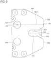
- the front end portion of the guide plate 700 does not have an arc shape, and a flat surface 702 is formed at the front end of the guide plate 700.
- the flat surface 702 is a surface perpendicular to the central axis of the screw shaft 210.
- a dotted line DL1 in FIG. 5 is the same as the dotted line DL1 shown in FIG. 3 .
- An intersection of the dotted line DL1 and the flat surface 702 is the first position P1 in the present illustrative embodiment.
- the flat surface 702 is a surface that includes the first position P 1, which is a position at the most front end of the guide plate 700.
- the same "second position P2" as in the first illustrative embodiment can be defined.
- a position of the flat surface 702 in the guide plate 700 is adjusted such that the distance L between the first position P1 and the second position P2 along the predetermined direction is one-fourth or less of the interval W.
- the same effects as those described in the first illustrative embodiment can also be achieved.
- the user when cutting the reinforcing bar RB placed on the floor FL, the user operates the cutting blade 111 in the closing direction with the flat surface 702 of the guide plate 700 abutting the floor FL. Since the entire flat surface 702 abuts the floor FL, the posture of the cutting device 10 during cutting can be more stable.
- a third illustrative embodiment is described.
- points different from the first illustrative embodiment will be mainly described, and descriptions of points common to those of the first illustrative embodiment will be omitted as appropriate.
- the present illustrative embodiment differs from the first illustrative embodiment in the configuration of the guide plate 700.
- each guide plate 700 in the present illustrative embodiment is divided into a base portion 700A, which is a portion overlapping the shaft 101, and a front end portion 700B, which is a portion on the front end side.
- the base portion 700A and the front end portion 700B are connected by slide shafts 751 and a screw shaft 752.
- the slide shaft 751 is a rod-shaped member that extends linearly in the direction parallel to the central axis of the screw shaft 210. An end on a front end side of the slide shaft 751 is fixed to the front end portion 700B. A portion on a rear end side of the slide shaft 751 is supported by the base portion 700A in a manner of being slidable in the direction parallel to the central axis of the screw shaft 210.
- the two slide shafts 751 are provided for one front end portion 700B. However, the number of slide shafts 751 may be different from the two.
- the screw shaft 752 is a rod-shaped member that extends linearly in the direction parallel to the central axis of the screw shaft 210.
- the screw shaft 752 has a male screw (not shown) formed on an outer peripheral surface thereof. An end on a front end side of the screw shaft 752 is fixed to the front end portion 700B.
- the screw shaft 752 is inserted through an adjustment nut 753 provided on the base portion 700A.
- a through hole (not shown) is formed in the adjustment nut 753, and the screw shaft 752 is inserted through the through hole.
- a female screw is formed on an inner surface of the through hole of the adjustment nut 753, and is screwed together with a male screw on the outer peripheral surface of the screw shaft 752.
- the adjustment nut 753 is fixed to the base portion 700A while being rotatable about a central axis of the adjustment nut 753.
- the screw shaft 752 moves along a longitudinal direction thereof, and the front end portion 700B also moves together with the screw shaft 210. That is, the entire guide plate 700 including the base portion 700A and the front end portion 700B expands and contracts along the longitudinal direction of the screw shaft 752.
- a part or all of the adjustment nut 753 may be exposed to the outside through an opening provided in the base portion 700A.
- the guide plate 700 is caused to expand and contract by rotating the adjustment nut 753 so that the protrusion amount of the guide plate 700 from the cutting blade 111 (corresponding to the distance L in FIG. 3 ) can be adjusted.
- the slide shafts 751, the screw shaft 752, and the adjustment nut 753 correspond to an "expansion and contraction mechanism" for causing the guide plate 700 to expand and contract.
- a configuration in which the above protrusion amount can be adjusted to be negative may also be adopted. That is, the cutting blade 111 may be configured to be adjustable such that the cutting blade 111 protrudes further toward the front end side than the guide plate 700.
- a specific configuration of the expansion and contraction mechanism may be different from the present illustrative embodiment.
- the adjustment nut 753 may be replaced with a worm gear.
Landscapes
- Engineering & Computer Science (AREA)
- Mechanical Engineering (AREA)
- Life Sciences & Earth Sciences (AREA)
- Forests & Forestry (AREA)
- Scissors And Nippers (AREA)
- Sawing (AREA)
- Shearing Machines (AREA)
- Milling Processes (AREA)
Abstract
Description
- The present disclosure relates to an electric cutting device.
- As an electric cutting device, a cutting device as described in
JP2021-171580A JP2021-171580A - By providing such guide plates, it becomes easy to set a positional relationship between the object to be cut and the cutting blades appropriately before cutting. When the cutting device is in a standby state, the cutting blades can be covered and protected by the guide plates.
- However, there may also be cases where if a floor or a wall is present near an object to be cut, for example, the object to be cut cannot be inserted into a recess of a guide plate to a sufficiently deep position, and the object to be cut cannot be cut.
- Illustrative aspects of the present disclosure provide a cutting device that can cut an object to be cut near a wall or the like while protecting a cutting blade with a guide plate.
- An electric cutting device includes: a pair of cutting blades configured to clamp and cut an object by rotating about a rotation central axis; an electric motor configured to generate a driving force necessary for operating the cutting blades; and a guide plate having a recess in a manner of receding along a predetermined direction, the recess being for housing the object in advance when the object is cut by the pair of cutting blades. An edge of the recess includes a pair of linear portions that are parallel to each other and face each other with a predetermined interval. When a position of the guide plate at a most front end along the predetermined direction is set as a first position, and a position in an operation range of each cutting blade at a most front end along the predetermined direction is set as a second position, a distance between the first position and the second position along the predetermined direction is one-fourth or less of the predetermined interval.
- In the cutting device configured as described above, the distance between the first position, which is the front end of the guide plate, and the second position, which is the front end of the operation range of the cutting blade is kept small so as to be about one-fourth or less of the width of the recess (the above predetermined interval).
- In many cases, the object has a diameter substantially equal to the width of the recess. Therefore, in the cutting device configured as described above, even if the object is in contact with a floor or a wall, it is possible to insert the object to a position that sufficiently overlaps a movable range of the cutting blade, and cut the object at that position.
- According to the present disclosure, a cutting device that can cut an object to be cut near a wall or the like while protecting a cutting blade with a guide plate is provided.
-
-
FIG. 1 is a diagram showing a configuration of a cutting device according to a first illustrative embodiment; -
FIG. 2 is a diagram showing a configuration of guide plates included in the cutting device according to the first illustrative embodiment; -
FIG. 3 is a diagram showing a configuration of the guide plates included in the cutting device according to the first illustrative embodiment; -
FIG. 4 is a diagram for illustrating a case where an object to be cut placed on a floor is cut; -
FIG. 5 is a diagram showing a configuration of guide plates included in a cutting device according to a second illustrative embodiment; and -
FIG. 6 is a diagram showing a configuration of guide plates included in a cutting device according to a third illustrative embodiment. - The present illustrative embodiment will be described below with reference to the accompanying drawings. In order to facilitate understanding of the description, the same components are denoted by the same reference numerals as much as possible in the drawings, and redundant descriptions will be omitted.
- A first illustrative embodiment will be described. A
cutting device 10 according to the present illustrative embodiment is an electric cutting device. Thecutting device 10 is configured as a device for cutting a reinforcing bar at a construction site or the like. A configuration of thecutting device 10 will be described mainly with reference toFIG. 1 . Thecutting device 10 includes ahousing 11, atrigger switch 12, acutting mechanism 100, aball screw 200, aspeed reducer 300, anelectric motor 400, acontrol board 500, and astorage battery 600. - The
housing 11 is a container that defines an outer shape of thecutting device 10. Thehousing 11 is made of resin, for example. Theball screw 200 described later, thespeed reducer 300 described later, and the like are housed inside thehousing 11. InFIG. 1 , a portion of thehousing 11 on a front side when viewed on paper is removed, and an internal configuration of thecutting device 10 is shown as a cross-sectional view. - The
trigger switch 12 is a switch operated by a finger of a user. The user can turn on thetrigger switch 12 by placing his or her finger on thetrigger switch 12 and pulling thetrigger switch 12 to the front side. When the user loosens his or her finger, the trigger switch 12 returns to an original position due to a force of a spring, and is turned off. When thetrigger switch 12 is switched between an ON state and the OFF state, a corresponding signal is transmitted to thecontrol board 500 described later. If the user performs an operation of switching thetrigger switch 12 into the ON state, cutting of the reinforcing bar is started. - The
cutting mechanism 100 is a portion configured to cut the reinforcing bar which is an object to be cut. Thecutting mechanism 100 includes a pair ofblade members 110 and a pair oflink members 120. - The
cutting blades 111 that clamp and cut the object to be cut are formed on therespective blade members 110. Theblade member 110 is held pivotably about ashaft 101 fixed to thehousing 11. In the present illustrative embodiment, therespective blade members 110 are arranged to face each other such that ridge lines of blade edges of thecutting blades 111 operate on trajectories passing through substantially the same plane. Accordingly, it is possible to switch between an opened state where therespective cutting blades 111 are spaced apart from each other and a closed state where therespective cutting blades 111 come into contact with (or close to) each other. In the example ofFIG. 1 , the pair ofcutting blades 111 are in the closed state. - Each
link member 120 is a rod-shaped member, and one end of thelink member 120 is connected to theblade member 110 via ashaft 102, and the other end of thelink member 120 is connected to aconnection member 230 described later via ashaft 231. Thelink member 120 and theblade member 110 are connected to each other in a manner of pivoting about theshaft 102. Similarly, thelink member 120 and theconnection member 230 are connected to each other in a manner of pivoting about theshaft 231. As will be described later, theconnection member 230 moves in a left-right direction inFIG. 1 by a driving force of theelectric motor 400. - If the
connection member 230 moves in a left direction from the state shown inFIG. 1 , theblade member 110 on an upper side ofFIG. 1 pivots counterclockwise, and theblade member 110 on a lower side ofFIG. 1 pivots clockwise. Accordingly, the pair ofcutting blades 111 change from the closed state to the opened state. On the other hand, when the pair ofcutting blades 111 are in the opened state, if theconnection member 230 moves in the right direction inFIG. 1 , theblade member 110 on the upper side ofFIG. 1 pivots clockwise, and theblade member 110 on the lower side ofFIG. 1 pivots counterclockwise. Accordingly, the pair ofcutting blades 111 return to the closed state. Accordingly, the pair ofblade members 110, the pair oflink members 120, and theconnection member 230 as a whole constitute a so-called "toggle link mechanism". - A pair of
guide plates 700 are provided near theblade members 110. Theguide plates 700 are plate-shaped members made of metal. Theguide plates 700 are disposed to sandwich theblade members 110 from both the front side and the back side inFIG. 1 when viewed on paper. Shapes of the pair ofguide plates 700 are substantially the same. As shown inFIG. 2 , eachguide plate 700 has arecess 710 formed therein. Therecess 710 is for housing the reinforcing bar in advance when thecutting blades 111 cut the reinforcing bar. - For convenience of description, a right side in
FIG. 1 will also be referred to as a "front end side" below, and a left side inFIG. 1 will be referred to as a "rear end side" below. Therecess 710 is formed to recede from the front end side toward the rear end side of theguide plate 700. When the cuttingdevice 10 is viewed from the side as shown inFIG. 1 andFIG. 2 , eachrecess 710 is formed at a position that includes thecutting blade 111 in the closed state. In a standby state where thecutting blades 111 are fully opened, as shown inFIG. 3 , thecutting blades 111 are retracted to the outside of therecesses 710, and theentire blade members 110 are hidden by theguide plates 700. - The
guide plates 700 have both a function of covering and protecting thecutting blades 111 in the standby state, and a function of guiding the reinforcing bar, which is the object to be cut, along therecesses 710 between the pair of cuttingblades 111. Theguide plates 700 further have a function of stabilizing a posture of the cuttingdevice 10 before and after cutting to be stable by sandwiching the reinforcing bar in therecesses 710. A specific configuration of theguide plate 700 will be described later. - Returning to
FIG. 1 , the description is continued. Theball screw 200 is a device for converting a rotational movement of theelectric motor 400 into a linear movement of theconnection member 230, thereby causing thecutting mechanism 100 to operate. Theball screw 200 includes ascrew shaft 210, anut 220, and theconnection member 230. - The
screw shaft 210 is a rod-shaped member that extends linearly from the rear end side to the front end side. A male screw is formed on an outer peripheral surface of thescrew shaft 210. When theelectric motor 400 is driven, thescrew shaft 210 rotates about a central axis thereof. - The
nut 220 is a substantially cylindrical member disposed to surround thescrew shaft 210 from an outer peripheral side. A female screw is formed on an inner peripheral surface of thenut 220, and is screwed to the male screw formed on the outer peripheral surface of thescrew shaft 210. While thenut 220 is allowed to move along a longitudinal direction of thescrew shaft 210, rotation about the central axis of thescrew shaft 210 is restricted. Therefore, when thescrew shaft 210 rotates about the central axis thereof, thenut 220 moves in the left-right direction inFIG. 1 along the central axis. - The
connection member 230 is a member attached to thenut 220 and is a member that moves along thescrew shaft 210 together with thenut 220. Theconnection member 230 is attached in a manner of protruding from thenut 220 toward the front end side. The pair oflink members 120 are connected to a portion of theconnection member 230 near an end on the front end side via theshaft 231 described above. - A
magnet 241 is attached to the outer peripheral surface of theconnection member 230. AHall sensor 242 is attached to thehousing 11 at a position near theconnection member 230. The position where theHall sensor 242 is attached is such that when thenut 220 moves to a rear end from the state shown inFIG. 1 and thecutting blades 111 are fully opened, theHall sensor 242 faces themagnet 241 of theconnection member 230. When thecutting blades 111 are fully opened, a signal is transmitted from theHall sensor 242 by facing themagnet 241, and the signal is input to thecontrol board 500. - The
speed reducer 300 is a device that is configured to reduce a rotation speed of anoutput shaft 410 of theelectric motor 400 and then transmit the rotation to thescrew shaft 210 of theball screw 200. - The
electric motor 400 is a rotating electrical machine for generating a driving force necessary for operating thecutting blades 111, and is, for example, a brushless DC motor. Theelectric motor 400 has theoutput shaft 410. Theoutput shaft 410 is a substantially cylindrical member, and a central axis thereof coincides with the central axis of thescrew shaft 210. A part of theoutput shaft 410 protrudes toward thespeed reducer 300 and is connected to thespeed reducer 300. - When current is supplied to a coil of the
electric motor 400, theoutput shaft 410 rotates about the central axis thereof. The rotation of theoutput shaft 410 is transmitted to thescrew shaft 210 via thespeed reducer 300, and causes thenut 220 to move toward the front end side or the rear end side. Accordingly, thecutting blades 111 of thecutting mechanism 100 are operated to open and close as described above. - A
rotation sensor 420 is provided inside theelectric motor 400. Therotation sensor 420 is configured to emit a pulse signal every time theoutput shaft 410 rotates by a predetermined angle. Therotation sensor 420 is provided on aboard 430 included in theelectric motor 400. The pulse signal from therotation sensor 420 is transmitted to thecontrol board 500. By counting the number of pulse signals, thecontrol board 500 is able to know a rotation angle of theoutput shaft 410 after a specific timing. Thecontrol board 500 is also able to know the rotation speed of theoutput shaft 410 based on the number of pulse signals input per unit time. Therotation sensor 420 may be a different type of a sensor from that of the present illustrative embodiment, or may be a sensor separately provided at a position different from theelectric motor 400 as long as the sensor can measure the rotation angle and the rotation speed of theoutput shaft 410. - The
control board 500 is a circuit board provided to control an overall operation of the cuttingdevice 10 including theelectric motor 400. Thecontrol board 500 includes an inverter circuit for adjusting current supplied to theelectric motor 400, a microcomputer for controlling a switching operation and the like in the inverter circuit, and the like. - The
storage battery 600 stores electric power necessary for operating theelectric motor 400 and thecontrol board 500, and is, for example, a lithium ion battery. In thecutting device 10, a portion in which thestorage battery 600 is built is detachable from thehousing 11 as a battery pack, and is connected to and charged by an external charger. Instead of such an aspect, a configuration may be adopted in which thestorage battery 600 can be charged while thestorage battery 600 is attached to thehousing 11. - If the user performs the operation of switching the
trigger switch 12 into the ON state, thecontrol board 500 detects the operation and causes thecutting blades 111 to operate in a closing direction to cut the reinforcing bar. In order to perform such control, thecontrol board 500 controls an operation of theelectric motor 400 while acquiring a current position of theconnection member 230. - In the present illustrative embodiment, a count value of the pulse signal input from the
rotation sensor 420 is calculated and acquired by thecontrol board 500 as the "current position" of theconnection member 230, based on a time when themagnet 241 and theHall sensor 242 face each other. - In order to enable acquisition of the current position of the
connection member 230, a reset operation may be performed when the cuttingdevice 10 is started up. In the reset operation, for example, theelectric motor 400 may be driven in a direction where the pair of cuttingblades 111 change from the closed state to the opened state, and theelectric motor 400 may be stopped at a time point when a detection signal from theHall sensor 242 is input. By starting counting the pulse signals from this time point, the current position of theconnection member 230 can be accurately acquired from then on. - The
control board 500 is configured to control an opening and closing operation of thecutting blades 111 by adjusting magnitude of current supplied to theelectric motor 400, for example, by PWM control. Thecontrol board 500 also controls a braking operation of thecutting blades 111 by performing a so-called "short braking" that short-circuits some of a plurality of coils included in theelectric motor 400 periodically or continuously. - The above control is merely an example. The control executed by the
control board 500 may cause thecutting blades 111 to operate according to the state of thetrigger switch 12, and various known kinds of control may be employed. - A specific configuration of the
guide plate 700 will be described. As shown inFIG. 2 , therecess 710 for housing the reinforcing bar, which is the object to be cut, is formed in a manner of receding from a front end of theguide plate 700 along a predetermined direction. The "predetermined direction" described here is a direction from the rear end side to the front end side, and is a direction parallel to the central axis of thescrew shaft 210. - An edge of the
recess 710 shown inFIG. 2 andFIG. 3 includes a pair oflinear portions 711 that are parallel to each other and face each other with a predetermined interval. The direction where thelinear portions 711 extend is the same as the predetermined direction described above. - As shown in
FIG. 3 , a distance (the above predetermined interval) between the pair oflinear portions 711 indicated by W. This W will also be referred to as an "interval W" below. The interval W may be said to be a width of therecess 710. A dimension of the interval W is set to be approximately equal to a typical diameter of the reinforcing bar which is the object to be cut by the cuttingdevice 10. - A reference numeral "C1" shown in
FIG. 3 represents a central axis of theshaft 101 extending along a depth direction when viewed on paper. Theblade member 110 and thecutting blade 111 rotate about this C1. That is, the central axis indicated by C1 corresponds to a rotation central axis of theblade member 110 and thecutting blade 111. The central axis indicated by C1 will also be referred to as a "rotation central axis C1" below. - A circle indicated by a dotted line DL2 in
FIG. 3 is a circle centered on the rotation central axis C1 and passing the front end of theguide plate 700. When viewed along the rotation central axis C1 as shown inFIG. 3 , an outer shape of the front end portion of theguide plate 700 has an arc shape with a part thereof coinciding with the dotted line DL2. In other words, the center of curvature of this portion is on the rotation central axis C1. The front end portion formed in an arc shape in this manner will also be referred to as an "arc portion 701" below. - A dotted line DL1 shown in
FIG. 3 is a line that passes through the rotation central axis C1 and is parallel to the central axis of thescrew shaft 210. P1, which is an intersection of the dotted line DL1 and the dotted line DL2, is located on thearc portion 701, and is located at a position on the most front end side of theguide plate 700 along the above "predetermined direction". This position will also be referred to as a "first position P1" below. - A circle indicated by a dotted line DL3 in
FIG. 3 is a circle centered on the rotation central axis C1 and passing a front end of thecutting blade 111. The dotted line DL3 can also be said to indicate a trajectory along which the front end of thecutting blade 111 moves. InFIG. 3 , the dotted lines DL1, DL2, and DL3, and the like are shown only for an upper side portion of therecess 710, and a configuration of the portion shown inFIG. 3 of the cuttingdevice 10 is symmetrical above and below therecess 710. - P2, which is an intersection of the dotted line DL1 and the dotted line DL3, represents a position at the most front end side along the above "predetermined direction" within an operation range of the
cutting blade 111. This position will also be referred to as a "second position P2" below. In the present illustrative embodiment, theguide plate 700 is configured such that a distance L between the first position P1 and the second position P2 along the above predetermined direction is zero or more and about one-fourth or less of the interval W. - Advantages of such a configuration will be described. At a construction site or the like, there is a case where it is desired to cut a reinforcing bar RB placed on a floor FL as shown in
FIG. 4 using a cutting device without lifting the reinforcing bar RB on the floor FL. However, there is a case where if the cutting device is provided with a guide plate, since the guide plate abuts the floor FL before the cutting blade, the reinforcing bar RB cannot be inserted to a sufficiently deep position in a recess of the guide plate, and the reinforcing bar RB cannot be cut. - Therefore, in the present illustrative embodiment, a protrusion amount of the
guide plate 700 is kept small such that L ≤ 1/4 × W as described above. - When cutting the reinforcing bar RB placed on the floor FL using the
cutting device 10 having such a configuration, as shown inFIG. 4 , the user moves thecutting blades 111 in the closing direction with thearc portions 701 of theguide plates 700 abutting the floor FL. Eachcutting blade 111 operates on the trajectory such that the front end passes the dotted line DL3 inFIG. 4 . - A dotted line DL4 in
FIG. 4 represents a position of thecutting blades 111 in the closed state. A point P3 is an intersection of the dotted line DL4 and the dotted line DL3. - When the
cutting blade 111 operates in the closing direction, the front end of thecutting blade 111 is closest to the floor FL when passing the second position P2. Then, the front end of thecutting blade 111 moves slightly away from the floor FL, and finally reaches the point P3. That is, the point P3 is closer to a deepest part of therecess 710 than the second position P2 in the predetermined direction. - As shown in
FIGS. 3 and4 , a distance between the first position P1 and the point P3 along the predetermined direction is more than the distance L between the first position P1 and the second position P2 and less than the interval W, and preferably, corresponds to approximately half of the interval W. In many cases, a diameter of the reinforcing bar RB is approximately equal to the interval W, which is the width of therecess 710. In this case, the front end of thecutting blade 111 that operates as described above passes approximately near the center of the reinforcing bar RB as shown inFIG. 4 . When each of thecutting blades 111 moves on the above trajectory and passes the reinforcing bar RB while cutting a part of the reinforcing bar RB, an area of the reinforcing bar RB that thecutting blade 111 does not pass also breaks due to plastic deformation. Therefore, the reinforcing bar RB can be cut at this position. The same applies when the reinforcing bar RB is located near a wall or the like that is perpendicular to the floor. - In this way, the cutting
device 10 according to the present illustrative embodiment can cut the reinforcing bar RB near the floor FL and the like while protecting thecutting blade 111 with theguide plate 700. - The
guide plate 700 of the present illustrative embodiment is formed with thearc portion 701 at the front end thereof. As described with reference toFIG. 3 , the center of curvature of thearc portion 701 is on the rotation central axis C1. Therefore, for example, when the floor FL has unevenness, even if a portion of thearc portion 701 other than the first position P1 abuts the floor FL, a minimum necessary distance can be secured between the front end of thecutting blade 111 and the floor FL. - A second illustrative embodiment will be described. In the following, points different from the first illustrative embodiment will be mainly described, and descriptions of points common to those of the first illustrative embodiment will be omitted as appropriate. The present illustrative embodiment differs from the first illustrative embodiment in the shape of the
guide plate 700. - As shown in
FIG. 5 , in the present illustrative embodiment, the front end portion of theguide plate 700 does not have an arc shape, and aflat surface 702 is formed at the front end of theguide plate 700. Theflat surface 702 is a surface perpendicular to the central axis of thescrew shaft 210. - A dotted line DL1 in
FIG. 5 is the same as the dotted line DL1 shown inFIG. 3 . An intersection of the dotted line DL1 and theflat surface 702 is the first position P1 in the present illustrative embodiment. Theflat surface 702 is a surface that includes the first position P 1, which is a position at the most front end of theguide plate 700. - Although not shown, in the present illustrative embodiment as well, the same "second position P2" as in the first illustrative embodiment can be defined. In the present illustrative embodiment, similarly to the first illustrative embodiment, a position of the
flat surface 702 in theguide plate 700 is adjusted such that the distance L between the first position P1 and the second position P2 along the predetermined direction is one-fourth or less of the interval W. In such an aspect, the same effects as those described in the first illustrative embodiment can also be achieved. - Similarly to
FIG. 4 , when cutting the reinforcing bar RB placed on the floor FL, the user operates thecutting blade 111 in the closing direction with theflat surface 702 of theguide plate 700 abutting the floor FL. Since the entireflat surface 702 abuts the floor FL, the posture of the cuttingdevice 10 during cutting can be more stable. - A third illustrative embodiment is described. In the following, points different from the first illustrative embodiment will be mainly described, and descriptions of points common to those of the first illustrative embodiment will be omitted as appropriate. The present illustrative embodiment differs from the first illustrative embodiment in the configuration of the
guide plate 700. - As shown in
FIG. 6 , eachguide plate 700 in the present illustrative embodiment is divided into abase portion 700A, which is a portion overlapping theshaft 101, and afront end portion 700B, which is a portion on the front end side. Thebase portion 700A and thefront end portion 700B are connected byslide shafts 751 and ascrew shaft 752. - The
slide shaft 751 is a rod-shaped member that extends linearly in the direction parallel to the central axis of thescrew shaft 210. An end on a front end side of theslide shaft 751 is fixed to thefront end portion 700B. A portion on a rear end side of theslide shaft 751 is supported by thebase portion 700A in a manner of being slidable in the direction parallel to the central axis of thescrew shaft 210. The twoslide shafts 751 are provided for onefront end portion 700B. However, the number ofslide shafts 751 may be different from the two. - The
screw shaft 752 is a rod-shaped member that extends linearly in the direction parallel to the central axis of thescrew shaft 210. Thescrew shaft 752 has a male screw (not shown) formed on an outer peripheral surface thereof. An end on a front end side of thescrew shaft 752 is fixed to thefront end portion 700B. Thescrew shaft 752 is inserted through anadjustment nut 753 provided on thebase portion 700A. - A through hole (not shown) is formed in the
adjustment nut 753, and thescrew shaft 752 is inserted through the through hole. A female screw is formed on an inner surface of the through hole of theadjustment nut 753, and is screwed together with a male screw on the outer peripheral surface of thescrew shaft 752. - The
adjustment nut 753 is fixed to thebase portion 700A while being rotatable about a central axis of theadjustment nut 753. When theadjustment nut 753 is rotated by the user, thescrew shaft 752 moves along a longitudinal direction thereof, and thefront end portion 700B also moves together with thescrew shaft 210. That is, theentire guide plate 700 including thebase portion 700A and thefront end portion 700B expands and contracts along the longitudinal direction of thescrew shaft 752. In order to facilitate such an operation, a part or all of theadjustment nut 753 may be exposed to the outside through an opening provided in thebase portion 700A. - In this way, by the user operation, the
guide plate 700 is caused to expand and contract by rotating theadjustment nut 753 so that the protrusion amount of theguide plate 700 from the cutting blade 111 (corresponding to the distance L inFIG. 3 ) can be adjusted. Theslide shafts 751, thescrew shaft 752, and theadjustment nut 753 correspond to an "expansion and contraction mechanism" for causing theguide plate 700 to expand and contract. A configuration in which the above protrusion amount can be adjusted to be negative may also be adopted. That is, thecutting blade 111 may be configured to be adjustable such that thecutting blade 111 protrudes further toward the front end side than theguide plate 700. - A specific configuration of the expansion and contraction mechanism may be different from the present illustrative embodiment. For example, the
adjustment nut 753 may be replaced with a worm gear. - The present illustrative embodiment has been described above with reference to specific examples. However, the present disclosure is not limited to these specific examples. Design changes made by those skilled in the art as appropriate to these specific examples are also included within the scope of the present disclosure as long as the changes have characteristics of the present disclosure. Elements included in each of the specific examples described above, and arrangement, conditions, shapes, and the like of the elements are not limited to those illustrated, and can be changed as appropriate. The elements included in each of the specific examples described above can be appropriately combined as long as no technical contradiction occurs.
Claims (11)
- An electric cutting device, comprising:a pair of cutting blades configured to clamp and cut an object by rotating about a rotation central axis;an electric motor configured to generate a driving force necessary for operating the cutting blades; anda guide plate having a recess in a manner of receding along a predetermined direction, the recess being for housing the object in advance when the object is cut by the pair of cutting blades,wherein an edge of the recess includes a pair of linear portions that are parallel to each other and face each other with a predetermined interval, andwherein when a position of the guide plate at a most front end along the predetermined direction is set as a first position, and a position in an operation range of each cutting blade at a most front end along the predetermined direction is set as a second position, a distance between the first position and the second position along the predetermined direction is one-fourth or less of the predetermined interval.
- The cutting device according to claim 1, further comprising:
an expansion and contraction mechanism configured to cause the guide plate to expand and contract along the predetermined direction. - The cutting device according to claim 1, wherein a portion of the guide plate that includes the first position is formed with an arc portion, an outer shape of the arc portion being an arc shape when viewed along the rotation central axis.
- The cutting device according to claim 3, wherein a center of curvature of the arc portion is on the rotation central axis.
- The cutting device according to claim 1, wherein a portion of the guide plate that includes the first position is formed with a flat surface.
- The cutting device according to claim 5, wherein the flat surface is perpendicular to the predetermined direction.
- The cutting device according to claim 7, wherein the second position is closer to the rotation central axis than the first position in the predetermined direction.
- The cutting device according to claim 1, wherein when a position of a front end of the each cutting blade in a closed state is set as a third position, the third position is closer to a deepest part of the recess than the second position in the predetermined direction.
- The cutting device according to claim 8, wherein a distance between the first position and the third position along the predetermined direction is more than the distance between the first position and the second position and less than the predetermined interval.
- The cutting device according to claim 8, wherein the distance between the first position and the third position along the predetermined direction corresponds to substantially half of the predetermined interval.
- An electric cutting device, comprising:a pair of cutting blades configured to clamp and cut an object by rotating about a rotation central axis;an electric motor configured to generate a driving force necessary for operating the cutting blades;a guide plate formed with a recess for housing the object in advance when the object is cut by the pair of cutting blades; andan expansion and contraction mechanism configured to cause the guide plate to expand and contract along a predetermined direction.
Applications Claiming Priority (8)
| Application Number | Priority Date | Filing Date | Title |
|---|---|---|---|
| JP2022210302A JP2024093739A (en) | 2022-12-27 | 2022-12-27 | Cutting device |
| JP2022210308A JP2024093744A (en) | 2022-12-27 | 2022-12-27 | Cutting device |
| JP2022210196A JP2024093671A (en) | 2022-12-27 | 2022-12-27 | Cutting device |
| JP2022210638 | 2022-12-27 | ||
| JP2022210362A JP2024093782A (en) | 2022-12-27 | 2022-12-27 | Cutting device |
| JP2022210372A JP2024093790A (en) | 2022-12-27 | 2022-12-27 | Cutting device |
| JP2022210296A JP2024093736A (en) | 2022-12-27 | 2022-12-27 | Cutting device |
| JP2022210594A JP2024093934A (en) | 2022-12-27 | 2022-12-27 | Cutting device |
Publications (2)
| Publication Number | Publication Date |
|---|---|
| EP4403322A2 true EP4403322A2 (en) | 2024-07-24 |
| EP4403322A3 EP4403322A3 (en) | 2024-09-18 |
Family
ID=89385883
Family Applications (7)
| Application Number | Title | Priority Date | Filing Date |
|---|---|---|---|
| EP23220296.0A Pending EP4403322A3 (en) | 2022-12-27 | 2023-12-27 | Cutting device |
| EP23220289.5A Pending EP4397458A1 (en) | 2022-12-27 | 2023-12-27 | Cutting device |
| EP23220287.9A Pending EP4393664A1 (en) | 2022-12-27 | 2023-12-27 | Cutting device |
| EP23220271.3A Pending EP4393663A1 (en) | 2022-12-27 | 2023-12-27 | Cutting device |
| EP23220293.7A Pending EP4403321A1 (en) | 2022-12-27 | 2023-12-27 | Cutting device |
| EP23220290.3A Pending EP4393665A1 (en) | 2022-12-27 | 2023-12-27 | Cutting device |
| EP23220295.2A Pending EP4393666A1 (en) | 2022-12-27 | 2023-12-27 | Cutting device |
Family Applications After (6)
| Application Number | Title | Priority Date | Filing Date |
|---|---|---|---|
| EP23220289.5A Pending EP4397458A1 (en) | 2022-12-27 | 2023-12-27 | Cutting device |
| EP23220287.9A Pending EP4393664A1 (en) | 2022-12-27 | 2023-12-27 | Cutting device |
| EP23220271.3A Pending EP4393663A1 (en) | 2022-12-27 | 2023-12-27 | Cutting device |
| EP23220293.7A Pending EP4403321A1 (en) | 2022-12-27 | 2023-12-27 | Cutting device |
| EP23220290.3A Pending EP4393665A1 (en) | 2022-12-27 | 2023-12-27 | Cutting device |
| EP23220295.2A Pending EP4393666A1 (en) | 2022-12-27 | 2023-12-27 | Cutting device |
Country Status (5)
| Country | Link |
|---|---|
| US (7) | US20240207955A1 (en) |
| EP (7) | EP4403322A3 (en) |
| KR (4) | KR20240104036A (en) |
| AU (4) | AU2023285960A1 (en) |
| CA (4) | CA3224768A1 (en) |
Citations (1)
| Publication number | Priority date | Publication date | Assignee | Title |
|---|---|---|---|---|
| JP2021171580A (en) | 2020-04-30 | 2021-11-01 | マックス株式会社 | Electric scissors |
Family Cites Families (10)
| Publication number | Priority date | Publication date | Assignee | Title |
|---|---|---|---|---|
| US2529895A (en) * | 1948-05-06 | 1950-11-14 | George V Anderson | Electrical cutting and punching machine |
| US5235750A (en) * | 1992-05-19 | 1993-08-17 | Brown Frank R | Hand tools |
| ES1050293Y (en) * | 2001-10-25 | 2002-07-01 | Hispaes S A | MOTORIZED CUTTING TOOL WITH AUTOMATION CUTTING DEVICE. |
| CN201493868U (en) | 2009-09-08 | 2010-06-02 | 南京德朔实业有限公司 | Electric shears |
| FR2957834B1 (en) * | 2010-03-24 | 2012-03-09 | Infaco | DEVICE FOR POSITIONALLY CONTROLLING TWO ELEMENTS RELATIVE TO EACH OTHER, SUCH AS BLADES OF CUTTER GENERATOR TOOLS AND CUTTING TOOL COMPRISING SAME |
| WO2014009363A1 (en) * | 2012-07-10 | 2014-01-16 | Gustav Klauke Gmbh | Pressing tool |
| JP6895312B2 (en) * | 2016-05-24 | 2021-06-30 | マクセル株式会社 | Electric tool |
| EP3333994B1 (en) * | 2016-12-09 | 2020-03-18 | CEMBRE S.p.A. | Working head for a compression or cutting tool |
| EP3746268B1 (en) * | 2018-01-30 | 2024-08-21 | Milwaukee Electric Tool Corporation | Hydraulic tool |
| JP6695486B1 (en) * | 2019-09-13 | 2020-05-20 | アルスコーポレーション株式会社 | Electric cutting device for pruning |
-
2023
- 2023-12-21 CA CA3224768A patent/CA3224768A1/en active Pending
- 2023-12-22 AU AU2023285960A patent/AU2023285960A1/en active Pending
- 2023-12-22 AU AU2023285964A patent/AU2023285964A1/en active Pending
- 2023-12-22 CA CA3224805A patent/CA3224805A1/en active Pending
- 2023-12-22 CA CA3224813A patent/CA3224813A1/en active Pending
- 2023-12-22 AU AU2023285963A patent/AU2023285963A1/en active Pending
- 2023-12-22 AU AU2023285962A patent/AU2023285962A1/en active Pending
- 2023-12-22 CA CA3224822A patent/CA3224822A1/en active Pending
- 2023-12-26 KR KR1020230191411A patent/KR20240104036A/en unknown
- 2023-12-26 KR KR1020230191421A patent/KR20240104038A/en unknown
- 2023-12-26 KR KR1020230191431A patent/KR20240104040A/en unknown
- 2023-12-26 KR KR1020230191441A patent/KR20240104041A/en unknown
- 2023-12-27 US US18/397,730 patent/US20240207955A1/en active Pending
- 2023-12-27 EP EP23220296.0A patent/EP4403322A3/en active Pending
- 2023-12-27 US US18/397,763 patent/US20240208090A1/en active Pending
- 2023-12-27 EP EP23220289.5A patent/EP4397458A1/en active Pending
- 2023-12-27 US US18/397,608 patent/US20240207954A1/en active Pending
- 2023-12-27 EP EP23220287.9A patent/EP4393664A1/en active Pending
- 2023-12-27 US US18/397,697 patent/US20240207952A1/en active Pending
- 2023-12-27 EP EP23220271.3A patent/EP4393663A1/en active Pending
- 2023-12-27 US US18/397,502 patent/US20240207953A1/en active Pending
- 2023-12-27 US US18/397,582 patent/US20240208088A1/en active Pending
- 2023-12-27 US US18/397,796 patent/US20240207956A1/en active Pending
- 2023-12-27 EP EP23220293.7A patent/EP4403321A1/en active Pending
- 2023-12-27 EP EP23220290.3A patent/EP4393665A1/en active Pending
- 2023-12-27 EP EP23220295.2A patent/EP4393666A1/en active Pending
Patent Citations (1)
| Publication number | Priority date | Publication date | Assignee | Title |
|---|---|---|---|---|
| JP2021171580A (en) | 2020-04-30 | 2021-11-01 | マックス株式会社 | Electric scissors |
Also Published As
| Publication number | Publication date |
|---|---|
| CA3224768A1 (en) | 2024-06-27 |
| EP4393664A1 (en) | 2024-07-03 |
| EP4403321A1 (en) | 2024-07-24 |
| CA3224822A1 (en) | 2024-06-27 |
| KR20240104041A (en) | 2024-07-04 |
| US20240207955A1 (en) | 2024-06-27 |
| KR20240104040A (en) | 2024-07-04 |
| KR20240104036A (en) | 2024-07-04 |
| AU2023285960A1 (en) | 2024-07-11 |
| EP4393665A1 (en) | 2024-07-03 |
| US20240207956A1 (en) | 2024-06-27 |
| EP4403322A3 (en) | 2024-09-18 |
| US20240208090A1 (en) | 2024-06-27 |
| AU2023285963A1 (en) | 2024-07-11 |
| EP4393666A1 (en) | 2024-07-03 |
| KR20240104038A (en) | 2024-07-04 |
| US20240207954A1 (en) | 2024-06-27 |
| US20240207952A1 (en) | 2024-06-27 |
| US20240208088A1 (en) | 2024-06-27 |
| EP4397458A1 (en) | 2024-07-10 |
| AU2023285964A1 (en) | 2024-07-11 |
| AU2023285962A1 (en) | 2024-07-11 |
| US20240207953A1 (en) | 2024-06-27 |
| CA3224805A1 (en) | 2024-06-27 |
| CA3224813A1 (en) | 2024-06-27 |
| EP4393663A1 (en) | 2024-07-03 |
Similar Documents
| Publication | Publication Date | Title |
|---|---|---|
| EP4403322A2 (en) | Cutting device | |
| US20050028371A1 (en) | Electric shaver | |
| JP2024093671A (en) | Cutting device | |
| CN209843601U (en) | Switch and lawn mower | |
| JP2024093744A (en) | Cutting device | |
| US20240208089A1 (en) | Cutting device | |
| JP2024093790A (en) | Cutting device | |
| JP2024093934A (en) | Cutting device | |
| JP2024093782A (en) | Cutting device | |
| CN118253666A (en) | Cutting device | |
| JP2021070105A (en) | Power tool | |
| JP2024093739A (en) | Cutting device | |
| JP7365636B2 (en) | cutting tools | |
| JP7340813B2 (en) | cutting tools | |
| TW202100315A (en) | Driving tool | |
| CN118253665A (en) | Cutting device | |
| JP2021070106A (en) | Power tool | |
| JP2598441Y2 (en) | electric toothbrush |
Legal Events
| Date | Code | Title | Description |
|---|---|---|---|
| PUAI | Public reference made under article 153(3) epc to a published international application that has entered the european phase |
Free format text: ORIGINAL CODE: 0009012 |
|
| STAA | Information on the status of an ep patent application or granted ep patent |
Free format text: STATUS: THE APPLICATION HAS BEEN PUBLISHED |
|
| AK | Designated contracting states |
Kind code of ref document: A2 Designated state(s): AL AT BE BG CH CY CZ DE DK EE ES FI FR GB GR HR HU IE IS IT LI LT LU LV MC ME MK MT NL NO PL PT RO RS SE SI SK SM TR |
|
| PUAL | Search report despatched |
Free format text: ORIGINAL CODE: 0009013 |
|
| AK | Designated contracting states |
Kind code of ref document: A3 Designated state(s): AL AT BE BG CH CY CZ DE DK EE ES FI FR GB GR HR HU IE IS IT LI LT LU LV MC ME MK MT NL NO PL PT RO RS SE SI SK SM TR |
|
| RIC1 | Information provided on ipc code assigned before grant |
Ipc: B23D 29/00 20060101ALI20240812BHEP Ipc: B26B 15/00 20060101AFI20240812BHEP |