EP4397426A1 - Cutting tool and method for producing cut workpiece - Google Patents
Cutting tool and method for producing cut workpiece Download PDFInfo
- Publication number
- EP4397426A1 EP4397426A1 EP22864345.8A EP22864345A EP4397426A1 EP 4397426 A1 EP4397426 A1 EP 4397426A1 EP 22864345 A EP22864345 A EP 22864345A EP 4397426 A1 EP4397426 A1 EP 4397426A1
- Authority
- EP
- European Patent Office
- Prior art keywords
- cutting
- rotation axis
- cutting tool
- elastic body
- cutting part
- Prior art date
- Legal status (The legal status is an assumption and is not a legal conclusion. Google has not performed a legal analysis and makes no representation as to the accuracy of the status listed.)
- Pending
Links
Images










Classifications
-
- B—PERFORMING OPERATIONS; TRANSPORTING
- B23—MACHINE TOOLS; METAL-WORKING NOT OTHERWISE PROVIDED FOR
- B23C—MILLING
- B23C5/00—Milling-cutters
- B23C5/02—Milling-cutters characterised by the shape of the cutter
- B23C5/06—Face-milling cutters, i.e. having only or primarily a substantially flat cutting surface
-
- B—PERFORMING OPERATIONS; TRANSPORTING
- B23—MACHINE TOOLS; METAL-WORKING NOT OTHERWISE PROVIDED FOR
- B23C—MILLING
- B23C5/00—Milling-cutters
- B23C5/16—Milling-cutters characterised by physical features other than shape
- B23C5/20—Milling-cutters characterised by physical features other than shape with removable cutter bits or teeth or cutting inserts
- B23C5/22—Securing arrangements for bits or teeth or cutting inserts
- B23C5/2204—Securing arrangements for bits or teeth or cutting inserts with cutting inserts clamped against the walls of the recess in the cutter body by a clamping member acting upon the wall of a hole in the insert
-
- B—PERFORMING OPERATIONS; TRANSPORTING
- B23—MACHINE TOOLS; METAL-WORKING NOT OTHERWISE PROVIDED FOR
- B23C—MILLING
- B23C5/00—Milling-cutters
- B23C5/16—Milling-cutters characterised by physical features other than shape
- B23C5/20—Milling-cutters characterised by physical features other than shape with removable cutter bits or teeth or cutting inserts
- B23C5/22—Securing arrangements for bits or teeth or cutting inserts
- B23C5/2204—Securing arrangements for bits or teeth or cutting inserts with cutting inserts clamped against the walls of the recess in the cutter body by a clamping member acting upon the wall of a hole in the insert
- B23C5/2226—Securing arrangements for bits or teeth or cutting inserts with cutting inserts clamped against the walls of the recess in the cutter body by a clamping member acting upon the wall of a hole in the insert for plate-like cutting inserts fitted on an intermediate carrier, e.g. shank fixed in the cutter body
-
- B—PERFORMING OPERATIONS; TRANSPORTING
- B23—MACHINE TOOLS; METAL-WORKING NOT OTHERWISE PROVIDED FOR
- B23C—MILLING
- B23C5/00—Milling-cutters
- B23C5/16—Milling-cutters characterised by physical features other than shape
- B23C5/20—Milling-cutters characterised by physical features other than shape with removable cutter bits or teeth or cutting inserts
- B23C5/22—Securing arrangements for bits or teeth or cutting inserts
- B23C5/24—Securing arrangements for bits or teeth or cutting inserts adjustable
- B23C5/2475—Securing arrangements for bits or teeth or cutting inserts adjustable the adjusting means being distance elements, e.g. shims or washers
-
- B—PERFORMING OPERATIONS; TRANSPORTING
- B23—MACHINE TOOLS; METAL-WORKING NOT OTHERWISE PROVIDED FOR
- B23C—MILLING
- B23C2220/00—Details of milling processes
- B23C2220/28—Finishing
Definitions
- Patent Documents 1 and 2 it is possible to tilt the rotation axis toward the front side in the feed direction in a machine whose machining direction is limited to a single axis as in a general-purpose milling cutter. However, it is difficult to apply this to a general machining center, etc. whose machining direction is one or more axes. That is, the milling tools discussed in Patent Documents 1 and 2 lack versatility.
- the wiper cutting edge located on the front side in the feed direction and the wiper cutting edge located on the rear side in the feed direction are identical in position along the rotation axis in the milling tool discussed in Patent Document 3. Therefore, the risk of crossed line pattern due to the flank part can be avoided, but the risk of the crossed line pattern due to the wiper cutting edges cannot be avoided.
- the first cartridge 15 is a member to be attached to the base 13.
- the first cartridge 15 may be used for forming the first pocket 9A in the body 3.
- the first pocket 9A is adjacent to the first cartridge 15 on a front side in the rotation direction O2 of the rotation axis O1 in the non-limiting embodiment illustrated in FIG. 2.
- FIG. 2 is a drawing of the cutting tool 1A illustrated in FIG. 1 as viewed from A1 direction (as viewed from the side).
- the first cutting part 5A may include a front surface 35.
- the front surface 35 is a surface located on the front side in the rotation direction O2 in the first cutting part 5A. There are no special limitations imposed on the shape of the front surface 35, but may have, for example, a planar shape or a curved shape, and may include concave-convex portions.
- the front surface 35 may include a first side 37, a second side 39, and a first corner 41.
- the first side 37 may be located on a side of the first end 3A.
- the second side 39 may be located on a side of the outer periphery away from the rotation axis O1.
- the first corner 41 may be a corner connecting to the first side 37 and the second side 39.
- the first cutting part 5A may include a third cutting edge 43 located on the first corner 41.
- the third cutting edge 43 may be sequentially disposed side by side with respect to the first cutting edge 27 or the second cutting edge 29.
- the third cutting edge 43 is not limited to having a curvilinear shape as illustrated in FIG. 6 , but may include a straight line shape or may have a circular arc shape.
- the first cutting part 5A may include a rear surface 45.
- the rear surface 45 is a surface located on a rear side in the rotation direction O2 in the first cutting part 5A. There are no special limitations imposed on the shape of the rear surface 45, but may have, for example, a planar shape or a curved shape, and may include concave-convex portions.
- the rear surface 45 of the first cutting part 5A is opposed to the first seating surface 21 of the first pocket 9A.
- the first seating surface 21 may be in contact with the rear surface 45 as in the non-limiting embodiment illustrated in FIG. 5 . In this case, a sliding direction of the rear surface 45 tends to become stable. As to the term "be in contact with” used herein, all of the first seating surface 21 and the rear surface 45 need not be in contact with each other without any gap therebetween. Specifically, a gap of 0.05-0.01 mm may be present partially between the first seating surface 21 and the rear surface 45.
- a position of the first cutting edge 27 at this time, that is, during machining is a first cutting edge position S1 (refer to FIG. 10 ).
- the first insert 23 in the cutting tool 1A may be a so-called wiper insert.
- the cutting insert 12 performs an ordinary milling process of a workpiece
- the first insert 23 may be a finishing insert for improving surface accuracy of a machined surface of the workpiece.
- the first insert 23 may be protruded toward the first end 3A compared with the cutting insert 12.
- Examples of the member having a high Young's modulus may include resins and rubbers.
- Examples of the resins may include polycarbonate resin, polyethylene terephthalate resin, acrylic resin, polyvinyl chloride resin, silicone resin, and epoxy resin.
- Examples of the rubbers may include natural rubbers and synthetic rubbers.
- the first seating surface 21 is not limited to having a shape such as that in an embodiment illustrated in FIG. 8 , but may have a planar shape or a curved shape, or may include concave convex portions.
- the term "inclined toward the front side in the rotation direction O2 as coming closer to the second end 3B" as used herein does not mean a strict continuous inclination, but there may be a part parallel to the rotation axis O1.
- the first seating surface 21 may include a first concave part 49 as in a non-limiting embodiment illustrated in FIG. 8 .
- the rear surface 45 may include a second concave part 51 as in a non-limiting embodiment illustrated in FIG. 9 .
- the second concave part 51 may be opposed to the first concave part 49 as in a non-limiting embodiment illustrated in FIG. 10 .
- the first elastic body 7A may be inserted into the first concave part 49 and the second concave part 51.
- the first elastic body 7A may be in contact with the first concave part 49 and the second concave part 51.
- first elastic body 7A If the first elastic body 7A is inserted into the first concave part 49 and the second concave part 51, it is easy to cause the first seating surface 21 and the rear surface 45 to come into contact with each other while causing the first elastic body 7A to be located between the body 3 and the first cutting part 5A. If the first elastic body 7A is in contact with the first concave part 49 and the second concave part 51, it is possible to efficiently transmit the urging force to the first cutting part 5A.
- the shape of the first concave part 49 is not particularly limited, and a width and a depth of the first concave part 49 are also not limited.
- the width of the first concave part 49 may be constant or changed.
- the first elastic body 7A may be fittingly crossed with the second concave part 51. With the configuration that the first elastic body 7A is fittingly crossed with the second concave part 51, the position of the first elastic body 7A tends to become stable. Accordingly, the first elastic body 7A can easily apply the urging force to the rear surface 45.
- a cutting tool 1B in a second embodiment includes a body 3, a first cutting part 5A, and a first elastic body 7A.
- a component of the cutting tool 1B in the second embodiment which has the same configuration as that in the first cutting tool 1A of the first embodiment, a detailed description thereof is omitted here by referring to the description of the first embodiment.
- FIG. 16 illustrating the cutting tool 1B in the second embodiment is a drawing corresponding to FIG. 10 .
- the first elastic body 7A of the cutting tool 1A in the first embodiment is configured with the pin 47 and the helical spring 48
- the first elastic body 7A of the cutting tool 1B in the second embodiment is composed of a member having a high Young's modulus.
- the method for manufacturing the machined product 101 in the non-limiting embodiment of the present disclosure may include the following steps (1) to (3).
Landscapes
- Engineering & Computer Science (AREA)
- Mechanical Engineering (AREA)
- Milling Processes (AREA)
Abstract
Description
- The present application claims priority to
Japanese Patent Application No. 2021-142555, filed September 1, 2021 - The present disclosure relates to a cutting tool and a method for manufacturing a machined product. Examples of the cutting tool may include a so-called milling tool (a milling cutter). The milling tool is usable for milling processes, such as face milling and end milling.
- As a cutting tool, milling tools have been known which are discussed in, for example,
WO 2013/029072 (Patent Document 1),WO 2004/080633 (Patent Document 2), andJapanese Unexamined Patent Publication No. 2005-111651 - A rotation axis of the milling tool is inclined toward a front side in the feed direction in the milling tools discussed in
Patent Documents Patent Document 3. This avoids the risk of causing the crossed line pattern on the machined surface of the workpiece due to the flank part. - As discussed in
Patent Documents Patent Documents - The wiper cutting edge located on the front side in the feed direction and the wiper cutting edge located on the rear side in the feed direction are identical in position along the rotation axis in the milling tool discussed in
Patent Document 3. Therefore, the risk of crossed line pattern due to the flank part can be avoided, but the risk of the crossed line pattern due to the wiper cutting edges cannot be avoided. - A cutting tool in an embodiment of the present disclosure includes a body, a cutting part, and an elastic body. The body extends from a front end toward a rear end along a rotation axis, and includes a pocket located on a side of the front end. The cutting part is located in the pocket and includes a cutting edge located on a side of the front end. The elastic body is located between the body and the cutting part, and applies an urging force in a direction toward the rear end to the cutting part. The pocket includes a first seating surface directed to a front side in a rotation direction of the rotation axis. The cutting part includes a rear surface which is located on a rear side in the rotation direction of the rotation axis and which is in contact with the first seating surface. The elastic body is in contact with the first seating surface and the rear surface. The rear surface is slidable toward the rear end.
-
-
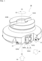
FIG. 1 is a perspective view illustrating a cutting tool in a first embodiment; -
FIG. 2 is a plan view of the cutting tool illustrated inFIG. 1 as viewed from A1 direction; -
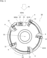
FIG. 3 is a plan view of the cutting tool illustrated inFIG. 1 as viewed from A2 direction; -
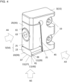
FIG. 4 is a perspective view illustrating a body (first cartridge), a first cutting part, a fixture, etc. in the cutting tool illustrated inFIG. 1 ; -
FIG. 5 is a plan view of a part illustrated inFIG. 4 as viewed from A3 direction; -
FIG. 6 is a plan view of the part illustrated inFIG. 4 as viewed from A4 direction; -
FIG. 7 is a plan view of the part illustrated inFIG. 4 as viewed from A5 direction; -
FIG. 8 is a perspective view illustrating the body inFIG. 4 ; -
FIG. 9 is a perspective view illustrating the first cutting part inFIG. 4 ; -
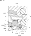
FIG. 10 is a sectional view of a cross section taken along line X-X illustrated inFIG. 6 , specifically a state of the part illustrated inFIG. 4 during machining; -
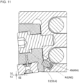
FIG. 11 is a sectional view of a state of the part illustrated inFIG. 10 during non-machining; -
FIG. 12 is a perspective view of a first modification of the body illustrated inFIG. 8 ; -
FIG. 13 is a perspective view of a first modification of the first cutting part illustrated inFIG. 9 ; -
FIG. 14 is a perspective view of a second modification of the body illustrated inFIG. 8 ; -
FIG. 15 is a perspective view of a second modification of the first cutting part illustrated inFIG. 9 ; -
FIG. 16 is a sectional view which illustrates a body, a first cutting part, a fixture, etc. in a cutting tool in a second embodiment, and which corresponds toFIG. 10 ; -
FIG. 17 is a perspective view illustrating a cutting tool in a third embodiment; -
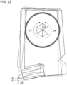
FIG. 18 is a plan view of the cutting tool illustrated inFIG. 17 as viewed from a side of a front end thereof; -
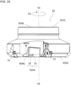
FIG. 19 is a perspective view illustrating a first cutting part, a fixture, a bearing member, etc. in the cutting tool illustrated inFIG. 17 ; -
FIG. 20 is a plan view of a part illustrated inFIG. 19 , which is a drawing corresponding toFIG. 6 ; -
FIG. 21 is an enlarged view of a cross section taken along line XXI-XXI illustrated inFIG. 18 ; -
FIG. 22 is a plan view of the part illustrated inFIG. 19 , which is a drawing corresponding toFIG. 5 ; -
FIG. 23 is a schematic diagram illustrating a positional relationship during machining and during non-machining in a part illustrated inFIG. 22 ; -
FIG. 24 is a perspective view illustrating a cutting tool in a fourth embodiment; -
FIG. 25 is a plan view of the cutting tool illustrated inFIG. 24 ; -
FIG. 26 is a plan view of the cutting tool illustrated inFIG. 24 as viewed from a side of a front end thereof; -
FIG. 27 is an enlarged view of a cross section taken along line XXVII-XXVII illustrated inFIG. 25 ; -
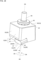
FIG. 28 is a perspective view illustrating a first cutting part, a fixture, a bearing member, etc. in the cutting tool illustrated inFIG. 24 ; -
FIG. 29 is a plan view of a part illustrated inFIG. 28 , which is a drawing corresponding toFIG. 5 ; -
FIG. 30 is a schematic explanatory diagram illustrating one of steps in a method for manufacturing a machined product in one embodiment; -
FIG. 31 is a schematic explanatory diagram illustrating one of the steps in the method for manufacturing a machined product in one embodiment; and -
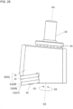
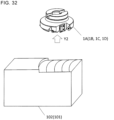
FIG. 32 is a schematic explanatory diagram illustrating one of the steps in the method for manufacturing a machined product in one embodiment. - Cutting tools in non-limiting first to fourth embodiments of the present disclosure are described in detail below with reference to the drawings. For convenience of description, the drawings referred to in the following illustrate, in simplified form, only main members necessary for describing the embodiments. The cutting tools of the present disclosure may therefore include any arbitrary structural member not illustrated in the drawings referred to. Dimensions of the members in each of the drawings faithfully represent neither dimensions of actual structural members nor dimensional ratios of these members. In a machining process, the term "during machining" means a state where the cutting tool and a workpiece are in contact with each other, and the term "during non-machining" means a state where the cutting tool and the workpiece are not in contact with each other. Unless otherwise noted, the drawings illustrate the state of the cutting tool during non-machining.
- The
cutting tool 1A in the first embodiment includes a rotation axis O1 and is a so-called rotary tool as in a non-limiting embodiment illustrated inFIG. 1 . Examples of the rotary tool may include milling cutters and end mills. The rotary tool in the non-limiting embodiment illustrated inFIG. 1 is a milling cutter. The rotation axis O1 is an axis during rotation of thecutting tool 1A, and is not included in thecutting tool 1A (body 3) as a concrete object. - The
cutting tool 1A includes abody 3, a cuttingpart 5 and anelastic body 7 as in the non-limiting embodiment illustrated inFIG. 1 , etc. Thebody 3 extends from afront end 3A to arear end 3B along the rotation axis O1. Thebody 3 includes apocket 9 located on a side of thefront end 3A. The cuttingpart 5 is located in thepocket 9 and includes acutting edge 11 located on a side of thefront end 3A (refer toFIG. 4 , etc.). Theelastic body 7 is located between thebody 3 and the cutting part 5 (refer toFIG. 10 , etc.). - The
body 3 is the part that becomes a base of thecutting tool 1A. Thepocket 9 may open into an outer peripheral surface of thebody 3 and an end surface on a side of thefront end 3A. There may be only onepocket 9, or there may be a plurality ofpockets 9 as in a non-limiting embodiment illustrated inFIG. 3. FIG. 3 is the drawing of thecutting tool 1A illustrated inFIG. 1 as viewed from A2 direction (as viewed from a side of thefront end 3A). If thebody 3 includes the plurality ofpockets 9, one of the plurality ofpockets 9 is afirst pocket 9A. There may be a plurality of cuttingparts 5 instead of including only one cuttingpart 5 as illustrated inFIG. 1 . If thecutting tool 1A includes the plurality ofpockets 9, the cuttingpart 5 located in thefirst pocket 9A is afirst cutting part 5A. - An insert may be attached to each of the pockets. A cutting
insert 12 may be attached as the insert to each of the plurality of pockets other than thefirst pocket 9A as in the non-limiting embodiment illustrated inFIG. 1 . There may be one or a plurality ofelastic bodies 7. If thecutting tool 1A includes the plurality ofelastic bodies 7, theelastic body 7 located between thebody 3 and thefirst cutting part 5A is a firstelastic body 7A. - A rotation direction O2 is not limited to a clockwise direction illustrated in
FIG. 1 . For example, in cases where thecutting tool 1A is configured to be reversed around the rotation axis O1 with respect to the configuration illustrated inFIG. 1 , the rotation direction O2 may be counterclockwise. - The
cutting tool 1A of the first embodiment has a columnar shape extending along the rotation axis O1 from thefront end 3A toward therear end 3B in the non-limiting embodiment illustrated inFIG. 1 . For the convenience of description, a portion located on the side of thefront end 3A and a portion located on the side of therear end 3B in thebody 3 may be respectively afirst end 3A and asecond end 3B in some cases. As is apparent from the fact that thecutting tool 1A includes thefirst pocket 9A, etc., thecutting tool 1A is not a strict columnar shape. A length of thebody 3 in a direction along the rotation axis O1 is, for example, 50-100 mm. An outer diameter of thebody 3 in a direction orthogonal to the rotation axis O1 is, for example, 100-300 mm. - The
body 3 is rotatable around the rotation axis O1. There are no special limitations imposed on the shape of thebody 3. Thebody 3 may have, for example, an approximately columnar shape or an approximately conical shape, and may include concave-convex portions, etc. - The
body 3 may be configured with one member or a plurality of members. For example, thebody 3 may include abase 13 and afirst cartridge 15 as in the non-limiting embodiment illustrated inFIG. 1 . Thebody 3 may include a member other than the base 13 and thefirst cartridge 15. - The
first cartridge 15 is a member to be attached to thebase 13. Thefirst cartridge 15 may be used for forming thefirst pocket 9A in thebody 3. Thefirst pocket 9A is adjacent to thefirst cartridge 15 on a front side in the rotation direction O2 of the rotation axis O1 in the non-limiting embodiment illustrated inFIG. 2. FIG. 2 is a drawing of thecutting tool 1A illustrated inFIG. 1 as viewed from A1 direction (as viewed from the side). - The
first cartridge 15 may include afirst hole 17 that is open as in a non-limiting embodiment illustrated inFIG. 5. FIG. 5 is a drawing of the part illustrated inFIG. 4 as viewed from A3 direction (as viewed from the side). Thefirst hole 17 may be used as an insertion hole for afirst fixture 19 when attaching thefirst cartridge 15 to thebase 13. Examples of thefirst fixture 19 may include a screw and a clamp. - The
first pocket 9A includes afirst seating surface 21 directed to the front in the rotation direction O2 of the rotation axis O1. This may be rephrased as follows: Thebody 3 includes thefirst seating surface 21. Thefirst cartridge 15 includes thefirst seating surface 21 in a non-limiting embodiment illustrated inFIG. 4 . - The
first cutting part 5A located in thefirst pocket 9A includes acutting edge 11 located on a side of thefirst end 3A. A machined product is manufacturable by machining a workpiece with thecutting edge 11. Thefirst cutting part 5A may be configured with one or a plurality of members. Thefirst cutting part 5A in the non-limiting embodiment illustrated inFIG. 4 includes afirst insert 23 and asecond cartridge 25. - The
first insert 23 includes thecutting edge 11 in the non-limiting embodiment illustrated inFIG. 4 . Thecutting edge 11 is located on a front side in the rotation direction O2 and a side of thefirst end 3A in thefirst insert 23. Thecutting edge 11 need not be located only at this part. For example, if thecutting edge 11 located on the front side in the rotation direction O2 and on the side of thefirst end 3A in thefirst insert 23 is afirst cutting edge 27, thefirst insert 23 may further include asecond cutting edge 29 located on the front side in the rotation direction O2 and on a side of an outer periphery in thefirst insert 23. Thefirst cutting edge 27 and thesecond cutting edge 29 are not limited to having a straight line shape as illustrated inFIG. 6 , but may have a curvilinear shape.FIG. 6 is a drawing of the part illustrated inFIG. 4 as viewed from A4 direction (as viewed from the front) . - The
first insert 23 is located on the front side in the rotation direction O2 with respect to thesecond cartridge 25. Thefirst insert 23 may have asecond hole 31 and may be fixed to thesecond cartridge 25 with asecond fixture 33, such as a screw, as in a non-limiting embodiment illustrated inFIG. 7. FIG. 7 is a drawing of the part inFIG. 4 as viewed from A5 direction (as viewed from a side of thefirst end 3A). - A length of the
first cutting part 5A in a direction along the rotation axis O1 is, for example, 30-50 mm. A length of thefirst cutting part 5A in a direction orthogonal to the rotation axis O1 is, for example, 15-35 mm. - The
first cutting part 5A may include afront surface 35. Thefront surface 35 is a surface located on the front side in the rotation direction O2 in thefirst cutting part 5A. There are no special limitations imposed on the shape of thefront surface 35, but may have, for example, a planar shape or a curved shape, and may include concave-convex portions. Thefront surface 35 may include afirst side 37, asecond side 39, and afirst corner 41. Thefirst side 37 may be located on a side of thefirst end 3A. Thesecond side 39 may be located on a side of the outer periphery away from the rotation axis O1. Thefirst corner 41 may be a corner connecting to thefirst side 37 and thesecond side 39. - The
first cutting edge 27 may be located on thefirst side 37. Because thefirst side 37 is located on thefirst end 3A as described above, thefirst cutting edge 27 located on thefirst side 37 can be located on the side of thefirst end 3A in the cuttingpart 5. Thesecond cutting edge 29 may be located on thesecond side 39. Because thesecond side 39 is located on the side away from the rotation axis O1 as described above, thesecond cutting edge 29 located on thesecond side 39 can be located on the side away from the rotation axis O1 in the cuttingpart 5. - The
first cutting part 5A may include athird cutting edge 43 located on thefirst corner 41. Thethird cutting edge 43 may be sequentially disposed side by side with respect to thefirst cutting edge 27 or thesecond cutting edge 29. Thethird cutting edge 43 is not limited to having a curvilinear shape as illustrated inFIG. 6 , but may include a straight line shape or may have a circular arc shape. - The
first cutting part 5A may include arear surface 45. Therear surface 45 is a surface located on a rear side in the rotation direction O2 in thefirst cutting part 5A. There are no special limitations imposed on the shape of therear surface 45, but may have, for example, a planar shape or a curved shape, and may include concave-convex portions. Therear surface 45 of thefirst cutting part 5A is opposed to thefirst seating surface 21 of thefirst pocket 9A. - The
first seating surface 21 may be in contact with therear surface 45 as in the non-limiting embodiment illustrated inFIG. 5 . In this case, a sliding direction of therear surface 45 tends to become stable. As to the term "be in contact with" used herein, all of thefirst seating surface 21 and therear surface 45 need not be in contact with each other without any gap therebetween. Specifically, a gap of 0.05-0.01 mm may be present partially between thefirst seating surface 21 and therear surface 45. - The first
elastic body 7A is located between thebody 3 and thefirst cutting part 5A as in a non-limiting embodiment illustrated inFIG. 10. FIG. 10 is a drawing illustrating a state where the part illustrated inFIG. 4 during machining is cut along the line X-X illustrated inFIG. 6 . A cross section along line X-X is the cross section that passes through a center of thesecond cartridge 25 and is parallel to the rotation axis O1. The cross section along line X-X may include a central axis N1 of the firstelastic body 7A (refer toFIG. 11 ). Specifically, the firstelastic body 7A is located between thefirst seating surface 21 in thefirst pocket 9A and therear surface 45 in thefirst cutting part 5A. In this case, the firstelastic body 7A may be in contact with thefirst seating surface 21 and therear surface 45. The firstelastic body 7A is capable of applying an urging force in a direction toward thesecond end 3B to thefirst cutting part 5A. Therear surface 45 is slidable toward thesecond end 3B. In other words, thefirst cutting part 5A is slidable because therear surface 45 is a part of thefirst cutting part 5A. - In a non-limiting embodiment illustrated in
FIG. 30 , thecutting tool 1A goes ahead toward a predetermined direction (so-called feed direction) while rotating around the rotation axis O1 during a machining process of a workpiece. Thefirst cutting part 5A is capable of contributing to the machining process when being located on a front side in the feed direction Y1 with respect to the rotation axis O1. Preferably, thefirst cutting part 5A does not contribute to the machining process when being located on a rear side in the feed direction Y1 with respect to the rotation axis O1. This is because a machined surface might be damaged to form the so-called crossed line pattern on the machined surface due to the fact that thefirst cutting part 5A comes into contact with the workpiece when being located on the rear side in the feed direction Y1 with respect to the rotation axis O1. - If the
first cutting part 5A comes into contact with the workpiece during the machining process of the workpiece, a cutting load tends to be applied from the workpiece to the cuttingpart 5 in a direction toward the workpiece, in other words, in a direction away from thesecond end 3B. Therefore, thefirst cutting part 5A tends to be drawn in the workpiece, and the machining process proceeds easily. A position of thefirst cutting edge 27 at this time, that is, during machining is a first cutting edge position S1 (refer toFIG. 10 ). - The
cutting tool 1A in the first embodiment includes the firstelastic body 7A. Therefore, if thefirst cutting part 5A is located on the rear side in the feed direction Y1 with respect to the rotation axis O1, the firstelastic body 7A is capable of applying an urging force in a direction toward thesecond end 3B to thefirst cutting part 5A. At this point, therear surface 45 of thefirst cutting part 5A is slidable toward thesecond end 3B. Hence, thefirst cutting part 5A is slidable toward thesecond end 3B when thefirst cutting part 5A is located on the rear side in the feed direction Y1 with respect to the rotation axis O1 than when thefirst cutting part 5A is located on the front side in the feed direction Y1 with respect to the rotation axis O1. A position of thefirst cutting edge 27 at this time, that is, during non-machining is a second cutting edge position S2 (refer toFIG. 11). FIG. 11 is a drawing that corresponds toFIG. 10 and illustrates a state of the part illustrated inFIG. 4 during non-machining. A distance (δZ) between the first cutting edge position S1 and the second cutting edge position S2 in the direction along the rotation axis O1 is, for example, 0.05-0.2 mm. - When the
first cutting part 5A is located on the rear side in the feed direction Y1 with respect to the rotation axis O1, thefirst cutting part 5A slides toward thesecond end 3B, thus making it difficult for thefirst cutting part 5A to come into contact with the workpiece. - Specifically, when the
first cutting part 5A is located on the front side in the feed direction Y1 with respect to the rotation axis O1, thefirst cutting part 5A comes into contact with the workpiece, and the workpiece can be subjected to the machining process by thefirst cutting part 5A. In contrast, when thefirst cutting part 5A is located on the rear side in the feed direction Y1 with respect to the rotation axis O1, thefirst cutting part 5A slides in a direction away from the workpiece, thus making it difficult for thefirst cutting part 5A to come into contact with the workpiece. - The risk of the crossed line pattern is reducible by the foregoing operations. Additionally, the above machining process can be carried out without tilting the rotation axis O1 of the cutting tool toward the front side in the feed direction. Therefore, a machining direction is not limited to one direction, thereby reducing a moving distance of the tool. Consequently, the above operations have high versatility and contribute to a reduction in machining time.
- The
first insert 23 in thecutting tool 1A may be a so-called wiper insert. Specifically, the cuttinginsert 12 performs an ordinary milling process of a workpiece, and thefirst insert 23 may be a finishing insert for improving surface accuracy of a machined surface of the workpiece. In this case, thefirst insert 23 may be protruded toward thefirst end 3A compared with the cuttinginsert 12. - The
elastic body 7 is located in the pocket 9 (first pocket 9A) to which thefirst insert 23 that is the wiper insert is attached, whereas theelastic body 7 need not be located in thepocket 9 to which the cuttinginsert 12 that is the insert performing the ordinary milling process is attached. In this case, thecutting tool 1A is capable of reducing the risk of the crossed line pattern while including a minimum required number ofelastic bodies 7. That is, it is possible to minimize a complicated structure for attaching theelastic body 7, and manufacturing cost for thecutting tool 1A can be reduced while reducing the risk of the crossed line pattern. - As described above, if the first
elastic body 7A is in contact with thefirst seating surface 21 and therear surface 45, the firstelastic body 7A can easily move a relative position of thefirst cutting part 5A (including the rear surface 45) with respect to the body 3 (including the first seating surface 21) toward thesecond end 3B. - The first
elastic body 7A is an elastically deformable member (elastic member) compared with thebody 3 and thefirst cutting part 5A. The firstelastic body 7A is not limited to one which is configured with a single elastic member, but a plurality of elastic members may be combined together. Alternatively, the firstelastic body 7A may be a structure including a member other than the elastic member. The term "member other than the elastic member" as used herein included in the firstelastic body 7A means one which is integrally used with the elastic member by being joined to the elastic member, and means a member that applies the urging force to an object together with the elastic member. The term "object" as used herein may be, for example, thefirst cutting part 5A. The member other than the elastic member may be, for example, apin 47 as in a non-limiting embodiment illustrated inFIG. 10 . - The elastic member is not limited to a specific material type. Examples of the elastic member may include various springs and members having a high Young's modulus. Specific examples of the spring may include leaf springs, disk springs and helical springs. The term "high Young's modulus" as used herein does not mean that it is necessary to have a specific value or more. However, it may be higher than, for example, the
body 3 and thefirst cutting part 5A. Young's modulus can be evaluated by, for example, well-known nanoindentation method. Thecutting tool 1A in the first embodiment employs ahelical spring 48. - Examples of the member having a high Young's modulus may include resins and rubbers. Examples of the resins may include polycarbonate resin, polyethylene terephthalate resin, acrylic resin, polyvinyl chloride resin, silicone resin, and epoxy resin. Examples of the rubbers may include natural rubbers and synthetic rubbers.
- The first
elastic body 7A applies an urging force to thefirst cutting part 5A. The term "urging force" as used herein may be a force acting when the elastically deformedelastic body 7 returns to its original state, in other words, an elastic force. The urging force may be not only such a force that the firstelastic body 7A directly applies to thefirst cutting part 5A, but also such a force that the firstelastic body 7A indirectly applies through other member to thefirst cutting part 5A. Alternatively, thefirst cutting part 5A may include a fulcrum, and the firstelastic body 7A may apply the urging force so that thefirst cutting part 5A can slide toward thesecond end 3B by rotating movement of thefirst cutting part 5A around the fulcrum. The firstelastic body 7A may apply the urging force to thefirst cutting part 5A in a direction other than the direction toward thesecond end 3B. For example, the firstelastic body 7A may apply the urging force toward the front side or the rear side in therotation direction 02. - The
rear surface 45, that is, thefirst cutting part 5A is slidable toward thesecond end 3B. The term "slidable toward thesecond end 3B" as used herein does not mean slidable only toward thesecond end 3B but means having an element (vector) that slides toward thesecond end 3B. Therefore, in the course of sliding of thefirst cutting part 5A, thefirst cutting part 5A may move in a direction toward the rotation axis O1 or away from the rotation axis O1, or may move to the front side or the rear side in the rotation direction O2. - The
first seating surface 21 may be inclined toward the front side in the rotation direction O2 as coming closer to thesecond end 3B as in the non-limiting embodiment illustrated inFIG. 5 . In other words, thefirst seating surface 21 may be inclined toward the rear side in the rotation direction O2 as coming closer to thefirst end 3A. In this case, a cutting load exerted on thefirst seating surface 21 tends to be dispersed in a direction along the rotation axis O1. This contributes to avoiding damage to thefirst cartridge 15, namely, thebody 3 due to the cutting load. When thefirst cutting part 5A performs a machining process of a workpiece while being located on the front side in the feed direction Y1 with respect to the rotation axis O1, thefirst cutting part 5A slides in a direction toward the workpiece, and the workpiece tends to be appropriately machined. Therefore, when thefirst cutting part 5A is located on the rear side in the feed direction Y1 with respect to the rotation axis O1, thefirst cutting part 5A is still unlikely to come into contact with the workpiece. - The
first seating surface 21 is not limited to having a shape such as that in an embodiment illustrated inFIG. 8 , but may have a planar shape or a curved shape, or may include concave convex portions. The term "inclined toward the front side in the rotation direction O2 as coming closer to thesecond end 3B" as used herein does not mean a strict continuous inclination, but there may be a part parallel to the rotation axis O1. - The
first seating surface 21 may include a firstconcave part 49 as in a non-limiting embodiment illustrated inFIG. 8 . Therear surface 45 may include a secondconcave part 51 as in a non-limiting embodiment illustrated inFIG. 9 . The secondconcave part 51 may be opposed to the firstconcave part 49 as in a non-limiting embodiment illustrated inFIG. 10 . The firstelastic body 7A may be inserted into the firstconcave part 49 and the secondconcave part 51. The firstelastic body 7A may be in contact with the firstconcave part 49 and the secondconcave part 51. If the firstelastic body 7A is inserted into the firstconcave part 49 and the secondconcave part 51, it is easy to cause thefirst seating surface 21 and therear surface 45 to come into contact with each other while causing the firstelastic body 7A to be located between thebody 3 and thefirst cutting part 5A. If the firstelastic body 7A is in contact with the firstconcave part 49 and the secondconcave part 51, it is possible to efficiently transmit the urging force to thefirst cutting part 5A. - As to the phrase that "the second
concave part 51 is opposed to the firstconcave part 49" as used herein, at least a part of anopening part 49A of the firstconcave part 49 and at least a part of anopening part 51A of the secondconcave part 51 may be continuous with each other (refer toFIG. 11 ). Hence, for example, a shape of theopening part 49A of the firstconcave part 49 and a shape of theopening part 51A of the secondconcave part 51 do not need to match, and all of theopening part 49A of the firstconcave part 49 and all of theopening part 51A of the secondconcave part 51 do not need to be opposed to each other. - The shape of the first
concave part 49 is not particularly limited, and a width and a depth of the firstconcave part 49 are also not limited. The width of the firstconcave part 49 may be constant or changed. - Similarly to the shape of the first
concave part 49, the shape of the secondconcave part 51 is not particularly limited. Similarly to the width and the depth of the firstconcave part 49, a width and a depth of the secondconcave part 51 are also not limited. - The first
elastic body 7A may be fittingly crossed with the firstconcave part 49. For example, thepin 47 and thehelical spring 48 are fittingly crossed with the firstconcave part 49 and are slidable in a direction along the central axis N1 of the firstelastic body 7A inFIG. 10 . As in a non-limiting embodiment illustrated inFIG. 11 , the central axis N1 of the firstelastic body 7A may coincide with a central axis N2 of the firstconcave part 49. With the configuration that the firstelastic body 7A is fittingly crossed with the firstconcave part 49, a position of the firstelastic body 7A tends to become stable. Accordingly, the firstelastic body 7A can easily apply the urging force to therear surface 45. The firstelastic body 7A may be fittingly crossed with the secondconcave part 51. With the configuration that the firstelastic body 7A is fittingly crossed with the secondconcave part 51, the position of the firstelastic body 7A tends to become stable. Accordingly, the firstelastic body 7A can easily apply the urging force to therear surface 45. - The
first seating surface 21 may include afirst flute 53 as in the non-limiting embodiment illustrated inFIG. 8 . Thefirst flute 53 may extend from a side of thefirst end 3A toward a side of thesecond end 3B. A shape of thefirst flute 53 is not limited to that in the embodiment illustrated inFIG. 8 , but may be a straight line shape or a curvilinear shape. A width and a depth of thefirst flute 53 need not be constant. The number of thefirst flute 53 is not limited to one but may be two or more. - The
rear surface 45 may include a firstconvex part 55 as in a non-limiting embodiment illustrated inFIG. 9 . The firstconvex part 55 may be inserted into thefirst flute 53. With the configuration that the firstconvex part 55 is inserted into thefirst flute 53, a sliding direction of therear surface 45 tends to become stable. A shape of the first convex part is not limited to that in the embodiment illustrated inFIG. 9 , but may be a straight line shape or a curvilinear shape. A width and a height of the firstconvex part 55 need not be constant.FIG. 9 is a perspective view of thefirst cutting part 5A as viewed from a side of therear surface 45. - The number of the first
convex part 55 is not limited to one but may be two or more. With the configuration that therear surface 45 includes a plurality of firstconvex parts 55 corresponding to thefirst flute 53 of thefirst seating surface 21, the sliding direction of therear surface 45 becomes more stable. The firstconvex part 55 may have a line shape corresponding to thefirst flute 53 as in the non-limiting embodiment illustrated inFIG. 9 . With the firstconvex part 55 having the line shape, the sliding direction of therear surface 45 becomes more stable. - The
first flute 53 may include the firstconcave part 49 as in the non-limiting embodiment illustrated inFIG. 8 . The firstconvex part 55 may include the secondconcave part 51 as in the non-limiting embodiment illustrated inFIG. 9 . In other words, thecutting tool 1A may include the firstelastic body 7A between thefirst flute 53 and the firstconvex part 55. With this configuration of thecutting tool 1A, thefirst flute 53 and the firstconcave part 55 can have a large width in the rotation direction of the rotation axis O1, and the sliding direction of therear surface 45 becomes more stable. - The
first flute 53 may come closer to the rotation axis O1 as coming closer to thesecond end 3B as in a non-limiting embodiment illustrated inFIG. 12 . In other words, thefirst flute 53 may go away from the rotation axis O1 as coming closer to thefirst end 3A. In this case, during machining, thecutting edge 11 moves toward thefirst end 3A and moves in a direction away from the rotation axis O1. Therefore, for example, in the case of including thesecond cutting edge 29, it is possible to enhance a feed rate in a milling process. As to the term "coming closer to the rotation axis O1 as coming closer to thesecond end 3B" as used herein, there is no need to strictly continue to come closer, and a part parallel to the rotation axis O1 may be included. - The first
convex part 55 may come closer to the rotation axis O1 as coming closer to thesecond end 3B as in a non-limiting embodiment illustrated inFIG. 13 . In other words, the firstconvex part 55 may go away from the rotation axis O1 as coming closer to thefirst end 3A. As to the term "coming closer to the rotation axis O1 as coming closer to thesecond end 3B" as used herein, there is no need to strictly continue to come closer, and a part parallel to the rotation axis O1 may be included. - The first
concave part 49 and the secondconcave part 51 may be located closer to the rotation axis O1 than thefirst flute 53. This may be rephrased as "the firstelastic body 7A may be closer to the rotation axis O1 than thefirst flute 53." That is, a distance between the rotation axis O1 and the firstelastic body 7A may be smaller than a distance between the rotation axis O1 and thefirst flute 53. A part away from the rotation axis O1 in thefirst seating surface 21 is subjected to a larger cutting load received from a machining surface during machining than a part close to the rotation axis O1 in thefirst seating surface 21. In the above case, resistance force that the firstelastic body 7A receives from the machining surface during the machining becomes lower, thereby avoiding the occurrence of breakage of the firstelastic body 7A. - The
rear surface 45 may include asecond flute 57 as in a non-limiting embodiment illustrated inFIG. 15 . Thesecond flute 57 may extend from a side of thefirst end 3A toward a side of thesecond end 3B. A shape of thesecond flute 57 is not particularly limited but may be, for example, a straight line shape or a curvilinear shape. A width and a depth of thesecond flute 57 need not be constant. The number of thesecond flute 57 is not limited to one but may be two or more. - The
first seating surface 21 may include a secondconvex part 59 as in a non-limiting embodiment illustrated inFIG. 14 . The secondconvex part 59 may be inserted into thesecond flute 57. With the configuration that the secondconvex part 59 is inserted into thesecond flute 57, a sliding direction of therear surface 45 tends to become stable. A shape of the secondconvex part 59 is not particularly limited. The shape of the secondconvex part 59 is not limited to that in the embodiment illustrated inFIG. 14 , but may be a straight line shape or a curvilinear shape. A width and a height of the secondconvex part 59 need not be constant. - The number of the second
convex part 59 is not limited to one but may be two or more. With the configuration that thefirst seating surface 21 includes a plurality of secondconvex parts 59 corresponding to thesecond flute 57 of therear surface 45, the sliding direction of therear surface 45 becomes more stable. The secondconvex part 59 may have a line shape corresponding to thesecond flute 57 as in the non-limiting embodiment illustrated inFIG. 14 . With the secondconvex part 59 having the line shape, the sliding direction of therear surface 45 becomes more stable. - The
second flute 57 may come closer to the rotation axis O1 as coming closer to thesecond end 3B as in the non-limiting embodiment illustrated inFIG. 15 . In other words, thesecond flute 57 may go away from the rotation axis O1 as coming closer to thefirst end 3A. In this case, during machining, thecutting edge 11 moves toward thefirst end 3A and moves in a direction away from the rotation axis O1. Therefore, for example, in the case of including thesecond cutting edge 29, it is possible to enhance the feed rate in the milling process. As to the term "coming closer to the rotation axis O1 as coming closer to thesecond end 3B" as used herein, there is no need to strictly continue to come closer, and a part parallel to the rotation axis O1 may be included. - The second
convex part 59 may come closer to the rotation axis O1 as coming closer to thesecond end 3B as in the non-limiting embodiment illustrated inFIG. 14 . In other words, the secondconvex part 59 may go away from the rotation axis O1 as coming closer to thefirst end 3A. As to the term "coming closer to the rotation axis O1 as coming closer to thesecond end 3B" as used herein, there is no need to strictly continue to come closer, and a part parallel to the rotation axis O1 may be included. - The first
concave part 49 and the secondconcave part 51 may be located closer to the rotation axis O1 than thesecond flute 57 as in the non-limiting embodiment illustrated inFIGs. 14 and15 . This may be rephrased as "the firstelastic body 7A may be located closer to the rotation axis O1 than thesecond flute 57." That is, the distance between the rotation axis O1 and the firstelastic body 7A may be smaller than a distance between the rotation axis O1 and thesecond flute 57. A part away from the rotation axis O1 in thefirst seating surface 21 is subjected to a larger cutting load received from the machining surface during machining than a part close to the rotation axis O1 in thefirst seating surface 21. In the above case, resistance force that the firstelastic body 7A receives from the machining surface during the machining becomes lower, thereby avoiding the occurrence of breakage of the firstelastic body 7A. - The
first cutting part 5A may include a first throughhole 61. The first throughhole 61 may open into thefront surface 35 and therear surface 45. Thefirst cutting part 5A may also include athird fixture 63 to be fixed to thebody 3 as in the non-limiting embodiment illustrated inFIG. 6 . Thethird fixture 63 may be inserted into the first throughhole 61. Examples of thethird fixture 63 may include a screw. Thethird fixture 63 is only required to maintain a state where thefirst cutting part 5A is located in thepocket 9. Because thefirst cutting part 5A is slidable, there is no need to completely fix thefirst cutting part 5A to thebody 3 by thethird fixture 63. With this configuration of thefirst cutting part 5A, it is possible to stably hold thefirst cutting part 5A while being held in a slidable state. Thefirst cutting part 5A may include a non-penetrating concave part instead of the first throughhole 61, and thefirst cutting part 5A may be fixed to thebody 3 by being fitted in the concave part. - The
body 3 may include a thirdconcave part 64. For example, thefirst cartridge 15 includes the thirdconcave part 64 in the non-limiting embodiment illustrated inFIG. 8 . Thethird fixture 63 may be inserted through the first throughhole 61 of thefirst cutting part 5A into the thirdconcave part 64. - A
cutting tool 1B in a second embodiment includes abody 3, afirst cutting part 5A, and a firstelastic body 7A. As to a component of thecutting tool 1B in the second embodiment which has the same configuration as that in thefirst cutting tool 1A of the first embodiment, a detailed description thereof is omitted here by referring to the description of the first embodiment.FIG. 16 illustrating thecutting tool 1B in the second embodiment is a drawing corresponding toFIG. 10 . - Although the first
elastic body 7A of thecutting tool 1A in the first embodiment is configured with thepin 47 and thehelical spring 48, the firstelastic body 7A of thecutting tool 1B in the second embodiment is composed of a member having a high Young's modulus. - The first
elastic body 7A of thecutting tool 1B in the second embodiment is not limited to having a specific shape but may have, for example, a columnar shape as in a non-limiting embodiment illustrated inFIG. 16 . An end surface of the firstelastic body 7A having the columnar shape may have a polygonal shape or a circular shape. - A
cutting tool 1C in a third embodiment includes abody 3, afirst cutting part 5A, and a firstelastic body 7A as in a non-limiting embodiment illustrated inFIGs. 17 to 23 . As to a component of thecutting tool 1C in the third embodiment which has the same configuration as that in thefirst cutting tool 1A of the first embodiment, a detailed description thereof is omitted here by referring to the description of the first embodiment.FIG. 21 is an enlarged sectional view illustrating a state where thecutting tool 1C in the third embodiment is cut along line XXI-XXI inFIG. 18 . A cross section along line XXI-XXI is a cross section that passes through a center of asecond cartridge 25 and is parallel to a rotation axis O1. - A
cutting tool 1D in a fourth embodiment includes abody 3, afirst cutting part 5A, and a firstelastic body 7A as in a non-limiting embodiment illustrated inFIGs. 24 to 29 . As to a component of thecutting tool 1D in the fourth embodiment which has the same configuration as that in thefirst cutting tool 1A of the first embodiment, a detailed description thereof is omitted here by referring to the description of the first embodiment.FIG. 27 is an enlarged sectional view illustrating a state where thecutting tool 1D of the fourth embodiment is cut along line XXVII-XXVII inFIG. 25 . A cross section along line XXVII-XXVII is a cross section that passes through a center of the firstelastic body 7A and is orthogonal to a rotation axis O1. - The
first cutting part 5A is linearly slidable by the presence of the flute (thefirst flute 53 or the second flute 57) in one of thefirst seating surface 21 and therear surface 45 in thecutting tool 1A in the first embodiment. Thecutting tool 1C in the third embodiment and thecutting tool 1D in the fourth embodiment are rotatable around the central axis (rotation axis O3) of athird fixture 63 as in the non-limiting embodiments illustrated inFIGs. 19 and28 . That is, thefirst cutting part 5A is slidable around thethird fixture 63. - The
cutting tool 1C and thecutting tool 1D may further include a bearingmember 65 between thebody 3 and thefirst cutting part 5A as in the non-limiting embodiments illustrated inFIGs. 20 and28 . In cases where thecutting tool 1C and thecutting tool 1D include this member, thefirst cutting part 5A is smoothly slidable around thethird fixture 63. - The bearing
member 65 may be located between the first throughhole 61 and thethird fixture 63. With thecutting tool 1C and thecutting tool 1D having the above configuration, thefirst cutting part 5A is smoothly slidable around thethird fixture 63. The first throughhole 61 in thecutting tool 1C may open into a surface on a side close to the rotation axis O1 and a surface on a side away from the rotation axis O1 in thefirst cutting part 5A as in the non-limiting embodiment illustrated inFIG. 19 . The first throughhole 61 in thecutting tool 1D may open into a surface on a side of thefirst end 3A and a surface on a side of thesecond end 3B in thefirst cutting part 5A as in the non-limiting embodiment illustrated inFIG. 28 . - With the
cutting tool 1C and thecutting tool 1D, during machining, thefirst cutting part 5A may rotate in a rotation direction O4 of the rotation axis O3, and thefirst cutting edge 27 may move to the first cutting edge position S1. During non-machining, thefirst cutting part 5A may rotate in a rotation direction O5 of the rotation axis O3, and thefirst cutting edge 27 may move to the second cutting edge position S2. The second cutting edge position S2 may be located closer to thesecond end 3B than the first cutting edge position S1 in the direction along the rotation axis O1. A distance (δZ) between the first cutting edge position S1 and the second cutting edge position S2 in the direction along the rotation axis O1 is, for example, 0.05-0.2 mm. The rotation direction O4 and the rotation direction O5 show a reverse directional relationship in the rotation direction of the rotation axis O3 as in the non-limiting embodiment illustrated inFIGs. 23 and27 . A solid line indicates thecutting tool 1C during machining, and a dotted line indicates thecutting tool 1C during non-machining inFIG. 23 . - Because the
first cutting part 5A linearly slides in the direction along the rotation axis O1 in thecutting tool 1A in the first embodiment, the central axis N1 of the firstelastic body 7A may extend in the direction along the rotation axis O1 as in the non-limiting embodiment illustrated inFIG. 11 . Because thefirst cutting part 5A slides around thethird fixture 63 in thecutting tool 1D in the third embodiment and thecutting tool 1D in the fourth embodiment, the central axis N1 of the firstelastic body 7A may extend in a direction vertical to a straight line connecting the rotation axis O3 and the firstelastic body 7A (a direction of a tangent line T1) in a cross section vertical to the rotation axis O3. At this point, an intersection P of the straight line connecting the rotation axis O3 and the firstelastic body 7A and the tangent line T1 may be present on the firstelastic body 7A as in a non-limiting embodiment illustrated inFIG. 21 . With thecutting tool 1C and thecutting tool 1D having the above configuration, the firstelastic body 7A is capable of efficiently applying the urging force to thefirst cutting part 5A. The central axis N1 of the firstelastic body 7A may coincide with the tangent line T1 as in the non-limiting embodiment illustrated inFIG. 21 . - In a side view of the
cutting tool 1C in the third embodiment, thefirst cutting edge 27 may be located on a front side in the rotation direction O2 of the rotation axis O1 than the rotation axis O3 as in the non-limiting embodiment illustrated inFIG. 22 . With thecutting tool 1C having this configuration, thefirst cutting edge 27 can easily move toward thefirst end 3A during machining. That is, the first cutting edge position S1 can easily be located on a side of thefirst end 3A than the second cutting edge position S2 in the direction along the rotation axis O1. - In a side view of the
cutting tool 1D in the fourth embodiment, thefirst cutting edge 27 may be located on a front side in the rotation direction O2 of the rotation axis O1 than the rotation axis O3 as in a non-limiting embodiment illustrated inFIG. 29 . With thecutting tool 1D having this configuration, thecutting edge 11 moves in the rotation direction O5 during machining. That is, thecutting edge 11 moves toward thefirst end 3A and moves in a direction away from the rotation axis O1. Therefore, it is possible to enhance the feed rate in the milling process in the case of including, for example, thesecond cutting edge 29. - The
third fixture 63 in the fourth embodiment may be inclined toward the rear side in the rotation direction O2 of the rotation axis O1 as coming closer to thesecond end 3B in the direction along the rotation axis O1. In other words, the central axis (rotation axis O3) of thethird fixture 63 may be inclined so as to come closer to the rear side in the rotation direction O2 of the rotation axis O1 as coming closer to thesecond end 3B in the direction along the rotation axis O1. The first throughhole 61 and the bearingmember 65 may also be inclined so as to come closer to the rear side in the rotation direction O2 of the rotation axis O1 as coming closer to thesecond end 3B in the direction along the rotation axis O1. With thecutting tool 1D having this configuration, thefirst cutting edge 27 can easily move toward thefirst end 3A during machining. - For example, cemented carbide and cermet are usable as a material of the cutting
insert 12 and thefirst insert 23. Examples of composition of the cemented carbide may include WC-Co, WC-TiC-Co and WC-TiC-TaC-Co. WC-Co is produced by adding cobalt (Co) to tungsten carbide (WC), followed by sintering. WC-TiC-Co is obtained by adding titanium carbide (TiC) to WC-CO. WC-TiC-TaC-Co is obtained by adding tantalum carbide (TaC) to WC-TiC-Co. - The cermet is a sintered composite material obtained by compositing metal into a ceramic component. Specific examples of the cermet may include those composed mainly of titanium compounds, such as titanium carbide (TiC) and titanium nitride (TiN).
- A surface of the cutting
insert 12 and thefirst insert 23 may be coated with a coating film by using chemical vapor deposition (CVD) method or physical vapor deposition (PVD) method. Examples of composition of the coating film may include titanium carbide (TiC), titanium nitride (TiN), titanium carbonitride (TiCN), and alumina (Al2O3). - For example, steel, cast iron and aluminum alloy are usable as material of the
base 13. From the viewpoint of enhancing toughness, steel may be used as the material of thebase 13. - The
cutting tools 1A to 1D of the present disclosure include thebody 3, the cuttingpart 5, and an urging means. The urging means is located between thebody 3 and thefirst cutting part 5A, and is an element capable of applying an urging force directed toward thesecond end 3B to thefirst cutting part 5A. The urging means may be located between thefirst seating surface 21 and therear surface 45. Examples of specific configurations of the urging means may include the firstelastic body 7A described above. The urging means is not limited to these configurations but may be those using, for example, air pressure, liquid pressure, magnetic force, etc. - In the
cutting tools 1A to 1D of the present disclosure, thefirst cutting part 5A is slidable toward thesecond end 3B by the urging force applied from the urging means, namely the firstelastic body 7A. Hence, thefirst cutting part 5A is slidable toward thesecond end 3B when thefirst cutting part 5A is located on a rear side in the feed direction Y1 with respect to the rotation axis as compared with when thefirst cutting part 5A is located on a front side in the feed direction Y1 with respect to the rotation axis. That is, the urging force is applied from the urging means to thefirst cutting part 5A so that the position of thecutting edge 11 during non-machining can come closer to thesecond end 3B than the position of thecutting edge 11 during machining. - With the configuration that the urging force is thus applied from the urging means to the
first cutting part 5A, a workpiece can be subjected to a machining process by thefirst cutting part 5A when thefirst cutting part 5A is located on the front side in the feed direction Y1 with respect to the rotation axis, whereas the workpiece is hardly subjected to the machining process by thefirst cutting part 5A when thefirst cutting part 5A is located on the rear side in the feed direction Y1 with respect to the rotation axis. Therefore, it is possible to reduce the risk of the crossed line pattern. - A method for manufacturing a machined product in a non-limiting embodiment of the present disclosure is described in detail below by exemplifying the case of using the
cutting tool 1A in the non-limiting first embodiment with reference toFIGs. 30 to 32. FIGs. 30 to 32 illustrate the steps of a machining process of aworkpiece 102 as a non-limiting embodiment of the method for manufacturing the machinedproduct 101. In order to facilitate visual understanding, hatching is applied to a cut part inFIGs. 31 and32 . - The method for manufacturing the machined
product 101 in the non-limiting embodiment of the present disclosure may include the following steps (1) to (3). - (1) The
cutting tool 1A may be brought near theworkpiece 102 in a feed direction Y1 by rotating thecutting tool 1A in a rotation direction O2 around a rotation axis O1 (refer toFIG. 30 ).
This step can be carried out, for example, by fixing theworkpiece 102 onto a table of a machine tool with thecutting tool 1A attached thereto, and by bringing thecutting tool 1A being rotated near theworkpiece 102. However, in this step, theworkpiece 102 and thecutting tool 1A may be brought near each other, and theworkpiece 102 may be brought near thecutting tool 1A. - (2) The
cutting tool 1A being rotated may be brought into contact with a desired position on a surface of theworkpiece 102 so as to cut out theworkpiece 102 by causing thecutting tool 1A to come closer to the workpiece 102 (refer toFIG. 31 ).
In this step, thecutting edge 11 may be brought into contact with the desired position on the surface of theworkpiece 102. - (3) The
cutting tool 1A may be moved away from theworkpiece 102 in Y2 direction (refer toFIG. 32 ). - Also in this step, similarly to the above step (1), the
cutting tool 1A may be relatively moved away from theworkpiece 102. For example, theworkpiece 102 may be moved away from thecutting tool 1A. Examples of the machining process may include plunge milling, profile milling, and ramping process, in addition to the milling process as in the non-limiting embodiment illustrated inFIG. 32 . - It is possible to offer excellent machinability by going through the foregoing steps.
- In cases where the machining process of the
workpiece 102 as described above is carried out a plurality of times, specifically, a plurality of machining processes of asingle workpiece 102 are carried out, the step of bringing thecutting tool 1A into contact with different portions of theworkpiece 102 may be repeated while keeping thecutting tool 1A rotated. - Examples of material of the
workpiece 102 may include carbon steel, alloy steel, stainless steel, cast iron, and nonferrous metals. -
- 1A to 1D
- cutting tool
- O1, O3
- rotation axis
- O2, O4, O5
- rotation direction
- 3
- body
- 3A
- front end (first end)
- 3B
- rear end (second end)
- 5
- cutting part
- 5A
- first cutting part
- 7
- elastic body
- 7A
- first elastic body
- 9
- 9A
- first pocket
- 11
- cutting edge
- 12
- cutting insert
- 13
- base
- 15
- first cartridge
- 17
- first hole
- 19
- first fixture
- 21
- first seating surface
- 23
- first insert
- 25
- second cartridge
- 27
- first cutting edge
- 29
- second cutting edge
- 31
- second hole
- 33
- second fixture
- 35
- front surface
- 37
- first side
- 39
- second side
- 41
- first corner
- 43
- third cutting edge
- 45
- rear surface
- N1, N2
- central axis
- Y1
- feed direction
- S1
- first cutting edge position
- S2
- second cutting edge position
- 47
- pin
- 48
- helical spring
- 49
- first concave part
- 49A
- opening part
- 51
- second concave part
- 51A
- opening part
- 53
- first flute
- 55
- first convex part
- 57
- second flute
- 59
- second convex part
- 61
- first through hole
- 63
- third fixture
- 64
- third concave part
- 65
- bearing member
- T1
- tangent line
- P
- intersection
- 101
- machined product
- 102
- workpiece
Claims (11)
- A cutting tool, comprising:a body which extends from a front end toward a rear end along a rotation axis and comprises a pocket located on a side of the front end;a cutting part which is located in the pocket and comprises a cutting edge located on a side of the front end; andan elastic body which is located between the body and the cutting part and applies an urging force in a direction toward the rear end to the cutting part, whereinthe pocket comprises a first seating surface directed to a front side in a rotation direction of the rotation axis,the cutting part comprises a rear surface which is located on a rear side in the rotation direction of the rotation axis and which is in contact with the first seating surface,the elastic body is in contact with the first seating surface and the rear surface, andthe rear surface is slidable toward the rear end.
- The cutting tool according to claim 1, wherein the first seating surface is inclined to a front side in the rotation direction as coming closer to the rear end.
- The cutting tool according to claim 1 or 2, whereinthe first seating surface comprises a first concave part,the rear surface comprises a second concave part opposed to the first concave part, andthe elastic body is in contact with the first concave part and the second concave part.
- The cutting tool according to any one of claims 1 to 3, whereinthe first seating surface comprises a first flute extending from a side of the front end toward a side of the rear end, andthe rear surface comprises a first convex part inserted into the first flute.
- The cutting tool according to claim 4, wherein the first flute comes closer to the rotation axis as coming closer to the rear end.
- The cutting tool according to claim 4 or 5, wherein the elastic body is located closer to the rotation axis than the first flute.
- The cutting tool according to any one of claims 1 to 6, whereinthe rear surface comprises a second flute extending from a side of the front end toward a side of the rear end, andthe first seating surface comprises a second convex part inserted into the second flute.
- The cutting tool according to claim 7, wherein the second flute comes closer to the rotation axis as coming closer to the rear end.
- The cutting tool according to any one of claims 1 to 8, wherein the cutting part further comprisesa front surface located on a front side in the rotation direction,a through hole opening in the front surface and the rear surface, anda fixture inserted into the through hole and fixed to the body.
- A cutting tool, comprising:a body which extends from a front end toward a rear end along a rotation axis and comprises a pocket located on a side of the front end;a cutting part which is located in the pocket and comprises a cutting edge located on a side of the front end; andan urging means located between the body and the cutting part, whereinan urging force is applied from the urging means to the cutting part so that a position of the cutting edge not in contact with a workpiece comes closer to the rear end than a position of the cutting edge in contact with the workpiece.
- A method for manufacturing a machined product, comprising:rotating the cutting tool according to any one of claims 1 to 10;bringing the cutting tool into contact with a workpiece; andmoving the cutting tool away from the workpiece.
Applications Claiming Priority (2)
| Application Number | Priority Date | Filing Date | Title |
|---|---|---|---|
| JP2021142555 | 2021-09-01 | ||
| PCT/JP2022/031751 WO2023032761A1 (en) | 2021-09-01 | 2022-08-23 | Cutting tool and method for producing cut workpiece |
Publications (2)
| Publication Number | Publication Date |
|---|---|
| EP4397426A1 true EP4397426A1 (en) | 2024-07-10 |
| EP4397426A4 EP4397426A4 (en) | 2025-10-15 |
Family
ID=85412263
Family Applications (1)
| Application Number | Title | Priority Date | Filing Date |
|---|---|---|---|
| EP22864345.8A Pending EP4397426A4 (en) | 2021-09-01 | 2022-08-23 | CUTTING TOOL AND METHOD FOR PRODUCING A CUTTING WORKPIECE |
Country Status (5)
| Country | Link |
|---|---|
| US (1) | US20240286207A1 (en) |
| EP (1) | EP4397426A4 (en) |
| JP (1) | JP7652909B2 (en) |
| CN (1) | CN117769471A (en) |
| WO (1) | WO2023032761A1 (en) |
Family Cites Families (26)
| Publication number | Priority date | Publication date | Assignee | Title |
|---|---|---|---|---|
| US3343431A (en) * | 1965-10-11 | 1967-09-26 | Donald H Boyer | Tool holder |
| BE793105A (en) * | 1971-12-24 | 1973-04-16 | Walter Gmbh Montanwerke | EXCHANGEABLE CUTTING INSERT MILLING TOOL |
| US3856427A (en) * | 1972-11-01 | 1974-12-24 | N Lovendahl | Adjustable boring tool |
| US4197042A (en) * | 1977-12-15 | 1980-04-08 | Everede Tool Company | Countersinking tool |
| US4188162A (en) * | 1977-12-27 | 1980-02-12 | The Valeron Corporation | Indexable insert drill |
| US4600341A (en) * | 1984-02-21 | 1986-07-15 | Board Harry B | Pocket reducing insert for toolholder and the like |
| KR100241147B1 (en) * | 1994-03-07 | 2000-03-02 | 후지무라 마사지카 | Cutting tools |
| JP3120034B2 (en) * | 1996-03-22 | 2000-12-25 | 兼房株式会社 | Milling cutter |
| US5921720A (en) * | 1998-01-23 | 1999-07-13 | Lemke; Carl | Ball nose cutting tool with center mounted tool bits |
| DE19848045C2 (en) * | 1998-10-17 | 2002-01-31 | Fette Wilhelm Gmbh | Insert milling cutters |
| JP3203424B2 (en) * | 1999-11-02 | 2001-08-27 | ホーコス株式会社 | Machine tool cutting device |
| SE526234C2 (en) | 2003-03-12 | 2005-08-02 | Sandvik Intellectual Property | Rotatable cutting tool as well as cutting with bevelled flat edge |
| JP2005111651A (en) | 2003-09-19 | 2005-04-28 | Tungaloy Corp | Tip, milling cutter, and machining method using the same |
| JP2006102924A (en) | 2004-10-08 | 2006-04-20 | Mitsubishi Materials Corp | Milling cutter |
| JP2006247776A (en) | 2005-03-09 | 2006-09-21 | Mitsubishi Materials Corp | Milling cutter |
| JP2008006568A (en) * | 2006-06-30 | 2008-01-17 | Mitsubishi Materials Corp | Insert detachable spherical cutter and insert for spherical cutter |
| US9623493B2 (en) * | 2008-11-19 | 2017-04-18 | Kennametal Inc. | Double-sided ball end mill cutting insert and tool therefor |
| JP2010149231A (en) * | 2008-12-25 | 2010-07-08 | Jtekt Corp | Cutting tool and method of polishing the same |
| IL199376A (en) | 2009-06-16 | 2013-08-29 | Iscar Ltd | Cutting tool having a bidirectional adjustment mechanism |
| US8858126B2 (en) * | 2009-09-25 | 2014-10-14 | Kennametal Inc. | Cutting tool with error proofing feature |
| DE102010008187A1 (en) * | 2010-02-16 | 2011-08-18 | KENNAMETAL INC., Pa. | Tool for cutting material processing and method for aligning cutting inserts in such a tool |
| AT12630U1 (en) | 2011-08-26 | 2012-09-15 | Ceratizit Austria Gmbh | DOUBLE-SIDED CUTTING INSERT FOR MILLING |
| US9862040B2 (en) * | 2014-09-30 | 2018-01-09 | Sandvik Intellectual Property Ab | Mechanism for enhanced, bi-directional fine adjustment of cutting insert cartridges in machine tools |
| EP3009216B1 (en) * | 2014-10-13 | 2020-05-06 | Sandvik Intellectual Property AB | Machining tool comprising a cutting insert positioning system |
| EP3587011B1 (en) * | 2018-06-21 | 2021-04-21 | AB Sandvik Coromant | An indexing system for a milling tool |
| CN210967166U (en) * | 2019-11-12 | 2020-07-10 | 苏州天音腾达机电工程有限公司 | Vertical face milling cutter |
-
2022
- 2022-08-23 US US18/574,313 patent/US20240286207A1/en active Pending
- 2022-08-23 EP EP22864345.8A patent/EP4397426A4/en active Pending
- 2022-08-23 WO PCT/JP2022/031751 patent/WO2023032761A1/en not_active Ceased
- 2022-08-23 CN CN202280044405.8A patent/CN117769471A/en active Pending
- 2022-08-23 JP JP2023545479A patent/JP7652909B2/en active Active
Also Published As
| Publication number | Publication date |
|---|---|
| CN117769471A (en) | 2024-03-26 |
| JP7652909B2 (en) | 2025-03-27 |
| US20240286207A1 (en) | 2024-08-29 |
| WO2023032761A1 (en) | 2023-03-09 |
| JPWO2023032761A1 (en) | 2023-03-09 |
| EP4397426A4 (en) | 2025-10-15 |
Similar Documents
| Publication | Publication Date | Title |
|---|---|---|
| EP3006142A1 (en) | Cutting insert and cutting tool, and method for producing cut workpieces using cutting tool | |
| US10239125B2 (en) | Cutting insert, cutting tool, and method for manufacturing machined product using same | |
| CN105745046B (en) | The manufacturing method of cutting insert, cutting element and being cut machining object | |
| EP3124143B1 (en) | Cutting insert, cutting tool, and method for manufacturing cut product | |
| US20180111206A1 (en) | Cutting tool and method for manufacturing the machined product | |
| JP2013027962A (en) | Holder for cutting tool, cutting tool, and method of cutting workpiece using the cutting tool | |
| JP6185376B2 (en) | Cutting insert, cutting tool and method of manufacturing workpiece | |
| EP4397426A1 (en) | Cutting tool and method for producing cut workpiece | |
| CN113474110B (en) | Turning tool and method for manufacturing cut product | |
| JPWO2017073663A1 (en) | CUTTING TOOL HOLDER, CUTTING TOOL, AND CUTTING PRODUCT PRODUCTION METHOD | |
| JP7645394B2 (en) | Cutting tool and method for manufacturing machined product | |
| JP7733214B2 (en) | Cutting insert, cutting tool, and method for manufacturing machined product | |
| US20260084221A1 (en) | Cutting insert, cutting tool, and method for manufacturing machined product | |
| JP7630531B2 (en) | Method for manufacturing cutting insert, cutting tool, and machined product | |
| JP7763261B2 (en) | Cutting insert, cutting tool, and method for manufacturing machined product | |
| JP6495681B2 (en) | Cutting insert, cutting tool, and manufacturing method of cut workpiece | |
| JP7045460B2 (en) | Manufacturing method of cutting tools and cutting products | |
| EP4494793A1 (en) | Cutting insert, cutting tool, and method for manufacturing cut workpiece | |
| JP7758646B2 (en) | Cutting tool and method for manufacturing machined product | |
| US20250222528A1 (en) | Cutting insert, cutting tool, and method for manufacturing machined product | |
| WO2025142154A1 (en) | Holder, cutting tool, and method for manufacturing cut workpiece | |
| JP2023094207A (en) | Manufacturing method for cutting tools and cut products | |
| JP2025150903A (en) | Holder, cutting tool, and method for manufacturing machined product | |
| WO2023132189A1 (en) | Cutting tool and method for producing cut workpiece | |
| CN118159375A (en) | Cutting insert, cutting tool, and method for producing cut product |
Legal Events
| Date | Code | Title | Description |
|---|---|---|---|
| STAA | Information on the status of an ep patent application or granted ep patent |
Free format text: STATUS: THE INTERNATIONAL PUBLICATION HAS BEEN MADE |
|
| PUAI | Public reference made under article 153(3) epc to a published international application that has entered the european phase |
Free format text: ORIGINAL CODE: 0009012 |
|
| STAA | Information on the status of an ep patent application or granted ep patent |
Free format text: STATUS: REQUEST FOR EXAMINATION WAS MADE |
|
| 17P | Request for examination filed |
Effective date: 20231227 |
|
| AK | Designated contracting states |
Kind code of ref document: A1 Designated state(s): AL AT BE BG CH CY CZ DE DK EE ES FI FR GB GR HR HU IE IS IT LI LT LU LV MC MK MT NL NO PL PT RO RS SE SI SK SM TR |
|
| DAV | Request for validation of the european patent (deleted) | ||
| DAX | Request for extension of the european patent (deleted) | ||
| A4 | Supplementary search report drawn up and despatched |
Effective date: 20250911 |
|
| RIC1 | Information provided on ipc code assigned before grant |
Ipc: B23C 5/06 20060101AFI20250905BHEP Ipc: B23C 5/22 20060101ALN20250905BHEP Ipc: B23C 5/24 20060101ALN20250905BHEP |