EP4397385A2 - Fahrsysteme mit dynamischer fahrfahrzeugbewegung - Google Patents
Fahrsysteme mit dynamischer fahrfahrzeugbewegung Download PDFInfo
- Publication number
- EP4397385A2 EP4397385A2 EP24177274.8A EP24177274A EP4397385A2 EP 4397385 A2 EP4397385 A2 EP 4397385A2 EP 24177274 A EP24177274 A EP 24177274A EP 4397385 A2 EP4397385 A2 EP 4397385A2
- Authority
- EP
- European Patent Office
- Prior art keywords
- ride
- movement
- vehicle
- vehicles
- rider
- Prior art date
- Legal status (The legal status is an assumption and is not a legal conclusion. Google has not performed a legal analysis and makes no representation as to the accuracy of the status listed.)
- Granted
Links
Images






Classifications
-
- A—HUMAN NECESSITIES
- A63—SPORTS; GAMES; AMUSEMENTS
- A63G—MERRY-GO-ROUNDS; SWINGS; ROCKING-HORSES; CHUTES; SWITCHBACKS; SIMILAR DEVICES FOR PUBLIC AMUSEMENT
- A63G31/00—Amusement arrangements
- A63G31/02—Amusement arrangements with moving substructures
-
- A—HUMAN NECESSITIES
- A63—SPORTS; GAMES; AMUSEMENTS
- A63G—MERRY-GO-ROUNDS; SWINGS; ROCKING-HORSES; CHUTES; SWITCHBACKS; SIMILAR DEVICES FOR PUBLIC AMUSEMENT
- A63G31/00—Amusement arrangements
- A63G31/16—Amusement arrangements creating illusions of travel
-
- A—HUMAN NECESSITIES
- A63—SPORTS; GAMES; AMUSEMENTS
- A63G—MERRY-GO-ROUNDS; SWINGS; ROCKING-HORSES; CHUTES; SWITCHBACKS; SIMILAR DEVICES FOR PUBLIC AMUSEMENT
- A63G33/00—Devices allowing competitions between several persons, not otherwise provided for
-
- G—PHYSICS
- G05—CONTROLLING; REGULATING
- G05B—CONTROL OR REGULATING SYSTEMS IN GENERAL; FUNCTIONAL ELEMENTS OF SUCH SYSTEMS; MONITORING OR TESTING ARRANGEMENTS FOR SUCH SYSTEMS OR ELEMENTS
- G05B15/00—Systems controlled by a computer
- G05B15/02—Systems controlled by a computer electric
Definitions
- the present disclosure relates generally to ride systems. More specifically, embodiments of the present disclosure relate to ride systems having ride vehicles that may move about a coordinated ride path in multiple directions relative to one another. The movement of the ride vehicles may be dynamically adjusted based on received inputs, such as inputs provided by riders of the ride vehicles.
- a ride system includes one or more ride vehicles.
- Each ride vehicle of the one or more ride vehicles includes a rider support configured to carry a rider, a support actuator coupled to the rider support and to a base of the ride vehicle, a ride vehicle movement system coupled to the base and configured to move the ride vehicle to traverse a ride area, and a roll system configured to move the rider support or the base angularly relative to the ride area.
- the support actuator is configured to move the rider support relative to the base.
- a ride system in an embodiment, includes a track and a ride vehicle configured to travel along the track.
- the ride vehicle includes a plurality of rider supports, where each rider support of the plurality of rider supports is configured to carry a respective rider.
- the ride vehicle also includes a plurality of support actuators, where each support actuator is coupled to a respective rider support of the plurality of rider supports and a base of the ride vehicle, and each support actuator is configured to move the respective rider support relative to the base.
- the ride vehicle includes a ride vehicle movement system integrated with the base and configured to move the ride vehicle along the track and a roll system configured to move the base and the plurality of rider supports angularly relative to the track.
- the ride vehicles may include mechanisms and portions (e.g., the rider supports) that may move vertically with respect to a surface of the ride area and/or with respect to a base of the ride vehicle, horizontally in various directions (e.g., may move in any planar direction, may spin, may turn, and so forth), and that may roll (e.g., lean and/or move angularly with respect to the surface of the ride area and/or with respect to the base of the ride vehicle).
- mechanisms and portions e.g., the rider supports
- the rider supports may move vertically with respect to a surface of the ride area and/or with respect to a base of the ride vehicle, horizontally in various directions (e.g., may move in any planar direction, may spin, may turn, and so forth), and that may roll (e.g., lean and/or move angularly with respect to the surface of the ride area and/or with respect to the base of the ride vehicle).
- the ride system and/or the ride vehicles may include a control system that controls movement of the ride vehicles within the ride area. For example, based on a position of a ride vehicle with respect to a ride path (e.g., based on an actual position of the ride vehicle relative to an intended position of the ride vehicle along the ride path), the control system may adjust a trajectory or traveled course of the ride vehicle.
- certain factors may affect the trajectory of the ride vehicle, such as obstacles within the ride area, a weight of the rider on the ride vehicle, a weight of other items disposed on or part of the ride vehicle, obstructions attached to the ride vehicle that may be dragging behind, in front of, or to the side of the ride vehicle, rider inputs (e.g., a rider shifting their weight, a rider turning a steering wheel or adjusting the trajectory of the ride vehicle generally, a rider adjusting a speed of the ride vehicle, etc.).
- rider inputs e.g., a rider shifting their weight, a rider turning a steering wheel or adjusting the trajectory of the ride vehicle generally, a rider adjusting a speed of the ride vehicle, etc.
- the control system may adjust the trajectory or the traveled course of the ride vehicle to generally follow the ride path and to account for such factors.
- the ride vehicles of the ride system may include a selected ride vehicle configured to lead the other ride vehicles.
- a rider riding the selected ride vehicle may provide an input, such as by shifting their weight, controlling a joystick or other hand controller, pressing a button, or a combination thereof.
- a controller of the selected ride vehicle and/or of the ride system may adjust the trajectory of the selected ride vehicle and/or movement of the rider support of the selected ride vehicle. For example, if the rider of the selected ride vehicle provides an input indicative of pulling the rider support of the selected ride vehicle upwardly and leaning the rider support toward the left, the controller may adjust the movement of the selected ride vehicle from the planned and choreographed ride path to generally move the rider support upwardly and to the left.
- the ride system controller may adjust the movement of some or all of the other ride vehicles and/or the rider supports of the other ride vehicles within the ride system.
- the adjustments to the movements of the other ride vehicles may generally correspond to the movement of the selected ride vehicle (e.g., may be based on a correlative adjustment/movement of the selected ride vehicle or portions thereof), may mirror the movement of the selected ride vehicle, and/or may be of a varying/different degree relative to the movement of the selected ride vehicle.
- the designation of the selected ride vehicle among the ride vehicles of the ride system may change during operation of the ride system.
- the selected ride vehicle in a first time period during a ride sequence of the ride system (e.g., a time sequence of operation of the ride system), the selected ride vehicle may be a first ride vehicle, and in a second time period during the ride sequence, the selected ride vehicle may be a second, different ride vehicle.
- the ride system allows the one or multiple riders of the ride system to at least partially control the ride vehicles during the ride sequence and while the riders ride the ride vehicles.
- the ride system may dynamically adjust the movement of the ride vehicles based on the rider input.
- the ride system may also include an auditory system configured to provide an auditory experience (e.g., sound effects, music, etc.) that generally corresponds to the choreographed movement of the ride vehicles and/or that may be adjusted based on the input provided at the ride vehicles.
- an auditory system configured to provide an auditory experience (e.g., sound effects, music, etc.) that generally corresponds to the choreographed movement of the ride vehicles and/or that may be adjusted based on the input provided at the ride vehicles.
- the ride system may include a ride station configured to dock/accommodate the ride vehicles.
- the ride system may dispatch some or all of the ride vehicles from the ride station during operation.
- the number of ride vehicles dispatched from the ride station may generally depend on a party size (e.g., one rider, two riders, three riders, four riders, six riders, ten riders, etc.) that is riding, or are about to ride, the ride vehicles of the ride system.
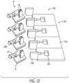
- the ride system may include a ride vehicle configured to move along a fixed track and that includes one or multiple rider supports configured to be ridden by multiple riders.
- each rider support may be coupled to a base of the ride vehicle, and the base may move along the track.
- Each rider support may move relative to the base and relative to one another as the ride vehicle moves along the track. The movement of each rider support may be planned and/or choreographed based on the position of the ride vehicle along the track.
- the ride vehicle may include a selected rider support configured to receive an input from a rider, and a controller of the ride system may control the movement of the selected rider support and/or other rider supports of the ride vehicle based on the input, such as by adjusting the planned and/or choreographed movement of the rider supports.
- a controller of the ride system may control the movement of the selected rider support and/or other rider supports of the ride vehicle based on the input, such as by adjusting the planned and/or choreographed movement of the rider supports.
- FIG. 1 is a rear perspective view of an embodiment of a ride system 10 including ride vehicles 12.
- each ride vehicle 12 and certain components of the ride vehicles 12 may be described with reference to a vertical axis or direction 14, a longitudinal axis or direction 16, and a lateral axis or direction 18.
- each ride vehicle 12 includes a base 20 and a rider support 22 (e.g., a riding assembly) coupled to the base 20 via a linkage assembly 24.
- the base 20 may move the ride vehicle 12 along a ride path and/or along a surface 26 of a ride area 28 of the ride system 10, and the rider support 22 may carry a rider (e.g., a user) of the ride vehicle 12.
- the rider may ride the ride vehicle 12 for entertainment and/or transportation purposes.
- the rider support 22 and/or the ride vehicle 12 may include ornamental features that enhance the rider's experience, such as features resembling an animal, a fictional character, an automobile, decorations, and/or other objects.
- the illustrated embodiment of the ride system 10 includes three ride vehicles 12, certain embodiments of the ride system 10 may include more or fewer ride vehicles 12 (e.g. one ride vehicle 12, two ride vehicles 12, four ride vehicles 12, five ride vehicles 12, eight ride vehicles 12, etc.).
- the ride vehicles 12 may share a common base 20.
- the common base 20 may be significantly wider than the illustrated bases 20 of FIG. 1 such that the common base 20 may accommodate multiple rider supports 22 and multiple linkage assemblies 24.
- each ride vehicle 12 may move along a choreographed ride path within the ride system 10 (e.g., along the surface 26 of the ride area 28) and/or may include mechanisms that enable the ride vehicles 12 and/or the rider supports 22 to move vertically (e.g., generally along the vertical axis 14), to move horizontally (e.g., generally along the longitudinal axis 16 and/or the lateral axis 18), and to roll while moving along the ride path (e.g., to rotate generally about the longitudinal axis 16 and/or the lateral axis 18).
- a choreographed ride path within the ride system 10 e.g., along the surface 26 of the ride area 28
- each ride vehicle 12 may move along a choreographed ride path within the ride system 10 (e.g., along the surface 26 of the ride area 28) and/or may include mechanisms that enable the ride vehicles 12 and/or the rider supports 22 to move vertically (e.g., generally along the vertical axis 14), to move horizontally (e.
- each rider may at least partially control/alter the movement of the ride vehicles 12 and/or the rider supports 22.
- the movement of the ride vehicles 12 along the choreographed ride path, in the various directions while moving along the ride path, and the ability of the riders to at least partially control the movements of the ride vehicles 12 and/or the rider supports 22 may provide an interactive and entertaining experience for the riders.
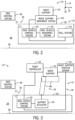
- FIG. 2 is a block diagram of an embodiment of the ride system 10 of FIG. 1 including the ride vehicle 12.
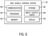
- the ride system 10 includes a ride control system 30 in communication with a ride vehicle control system 32 of the ride vehicle 12.
- the ride control system 30 and the ride vehicle control system 32 are communicatively coupled via a wireless connection 34 (e.g., Wi-Fi, Bluetooth, etc.).
- the ride control system 30 and the ride vehicle control system 32 may be communicatively coupled via a wired connection (e.g., Ethernet, universal serial bus (USB), CANbus, ISObus, etc.).
- a wired connection e.g., Ethernet, universal serial bus (USB), CANbus, ISObus, etc.
- the ride vehicle 12 includes a rider support movement system 40 (e.g., a riding assembly movement system), a ride vehicle movement system 42, and a roll system 44 communicatively coupled to the ride vehicle control system 32, such that the ride vehicle control system 32 may control the rider support movement system 40, the ride vehicle movement system 42, and the roll system 44.
- the rider support movement system 40, the ride vehicle movement system 42, and/or the roll system 44 may be directly communicatively coupled to the ride control system 30, such that the ride control system 30 may control the rider support movement system 40, the ride vehicle movement system 42, and/or the roll system 44.
- the rider support movement system 40 may move the rider support 22 with respect to the base 20 and/or along the vertical axis 14 and/or the longitudinal axis 16.
- the ride vehicle movement system 42 may move the ride vehicle 12 along the surface 26 of the ride area 28 of the ride system 10 generally along the longitudinal axis 16 and/or the lateral axis 18.
- the ride vehicle movement system 42 may move the ride vehicle 12 in any planar direction (e.g., along a plane parallel to the surface 26 of the ride area 28), may turn the ride vehicle 12, and may spin the ride vehicle 12.
- the roll system 44 may roll or angle the ride vehicle 12 (e.g., move the ride vehicle 12 generally angularly and/or tilt the ride vehicle 12) and/or the rider support 22 relative to the surface 26 of the ride area 28 of the ride system 10 and generally about the longitudinal axis 16.
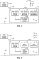
- FIG. 3 is a block diagram of an embodiment of the ride system 10 of FIG. 1 including the rider support movement system 40 of the ride vehicle 12.
- the rider support movement system 40 may move the rider support 22 generally along the vertical axis 14 and/or along the longitudinal axis 16. Additionally, the rider support movement system 40 may move the rider support 22 with respect to the base 20 and/or the surface 26 of the ride area 28 of the ride system 10.
- the rider support movement system 40 includes the linkage assembly 24, a support actuator 50, a rider support position sensor 52, and a rider controller 54.
- the support actuator 50 is configured to actuate to cause the linkage assembly 24 to move the rider support 22 relative to the base 20 and/or the surface 26 of the ride area 28.
- the support actuator 50 may be a piston, a hydraulic cylinder, a pneumatic cylinder, another suitable actuator, or the like, and may be coupled to the linkage assembly 24.
- the linkages 56 of the linkage assembly 24 may rotate relative to one another (e.g., via a pivot point at which the linkages 56 are coupled) to cause the rider support 22 to move relative to the base 20 and/or the surface 26 of the ride area 28.
- a first linkage 56 may be coupled to the support actuator 50 and to a second linkage 56.
- the support actuator 50 may move the first linkage 56, which may cause movement of the second linkage 56 and the rider support 22.
- the linkage assembly 24 may include additional mechanisms to enable/cause the movement of the rider support 22 generally along the vertical axis 14 and/or along the longitudinal axis 16, such as a pin connecting the linkages 56, an additional actuator coupled to and/or configured to move both the linkages 56, and other suitable mechanisms.
- the vertical and/or longitudinal motion caused by the rider support movement system 40 may be combined with the movement caused by the ride vehicle movement system 42 and/or the roll movement caused by the roll system 44.
- the rider support movement system 40 may include movement mechanisms in addition to or in place of the linkage assembly 24 and/or the support actuator 50 configured to move the rider support 22 relative to the base 20 and/or the surface 26 of the ride area 28.
- the ride vehicle control system 32 may adjust the vertical and/or longitudinal position of the rider support 22 relative to the base 20 and/or the surface 26 of the ride area 28. For example, the ride vehicle control system 32 may output a signal to the support actuator 50 to actuate to cause the linkage assembly 24 to move the rider support 22.
- the support actuator 50 may be omitted or may be integral to the linkage assembly 24, such that the ride vehicle control system 32 may communicate directly with the linkage assembly 24 to cause the linkage assembly 24 to move the rider support 22.
- the ride control system 30 may communicate directly with the linkage assembly 24, or portions thereof, to control the movement of the rider support 22.
- the ride control system 30 may control vertical and/or longitudinal movement of the rider support 22 of the ride vehicle 12 based on respective positions of other rider supports 22 of other ride vehicles 12. For example, based on another rider support 22 of another, separate ride vehicle 12 being at a first position, the ride control system 30 may control the movement/position of the rider support 22 of the ride vehicle 12. As such, the ride control system 30 may control the movement/position of the rider support 22 of each ride vehicle 12 individually (e.g., independently, separately, and/or differently).
- the rider controller 54 is coupled to the rider support 22 and communicatively coupled to the ride vehicle control system 32.
- the rider controller 54 may be any suitable controller configured to receive an input from the rider indicative of adjustment to the movement and/or position of the rider support 22, such as a joystick, a gaming controller, or another type of hand controller.
- the rider controller 54 may be integral to the rider support 22, such as included in handlebars of the rider support 22 (e.g., the rider may provide an input by moving the handlebars, by pressing button(s) on the handlebars, or turning certain mechanisms of the handlebars), included in a body of the rider support 22 (e.g., the rider may shift their weight to provide an input), or incorporated into the rider support 22 in other manners.
- the rider controller 54, or the ride vehicle 12 generally, may include sensors configured to detect the rider shifting their weight while positioned on the rider support 22, such as inertial sensors, accelerometers, pressure sensors, and/or other sensors configured to detect a shift in weight and/or a shift in weight distribution.
- the rider controller 54 may provide an interactive experience for a rider positioned on the rider support 22 by allowing the rider to at least partially control the movement/position of the rider support 22 and/or the ride vehicle 12.
- FIG. 4 is a block diagram of a side view of an embodiment of the ride system 10 of FIG. 1 including the ride vehicle movement system 42 of the ride vehicle 12.
- the ride vehicle movement system 42 may move the ride vehicle 12 generally along the longitudinal axis 16 and/or the lateral axis 18 and in any planar direction.
- the ride vehicle movement system 42 may also turn and/or spin the ride vehicle 12 along the surface 26 of the ride area 28 of the ride system 10.
- the ride vehicle movement system 42 may turn the ride vehicle 12 in a first direction while spinning the ride vehicle 12 in a second direction.
- the ride vehicle movement system 42 may turn the ride vehicle 12 toward the left while spinning the ride vehicle 12 to the right (e.g., while spinning the ride vehicle 12 clockwise if viewed from a top view).
- the ride vehicle movement system 42 includes a ride vehicle movement actuator 60, a ride vehicle movement mechanism 62, and a ride vehicle position sensor 64.
- the ride vehicle movement actuator 60 may actuate to cause the ride vehicle movement mechanism 62 to move the ride vehicle 12.
- the ride vehicle movement actuator 60 may be a piston, a hydraulic cylinder, a pneumatic cylinder, another suitable actuator, and the like, and may be coupled to the ride vehicle movement mechanism 62.
- the ride vehicle movement mechanism 62 may rotate, turn, or perform any other suitable movement to cause the ride vehicle 12 to move along the surface 26 of the ride area 28 of the ride system 10.
- the ride vehicle movement mechanism 62 may be wheels, spheres (e.g., steel or rubber balls), a track system, another suitable movement mechanism, or a combination thereof.
- the ride vehicle 12 may include more or fewer ride vehicle movement mechanisms 62 (e.g., two ride vehicle movement mechanisms 62, three ride vehicle movement mechanisms 62, five ride vehicle movement mechanisms 62, etc.) configured to move the ride vehicle 12 along the surface 26 of the ride area 28.
- the motion caused by the ride vehicle movement system 42 may be combined with the rider support movement caused by the rider support movement system 40. For example, while the rider support 22 moves relative to the base 20 and/or the surface 26 of the ride area 28, the ride vehicle movement system 42 may turn, spin, or otherwise move the ride vehicle 12 along the surface 26 of the ride area 28 of the ride system 10.
- the ride vehicle position sensor 64 may output a signal indicative of a position of the ride vehicle 12 within the ride system 10.
- the ride vehicle position sensor 64 may sense a position of the ride vehicle 12 along the longitudinal axis 16, along the lateral axis 16, relative to another ride vehicle 12, relative to a ride path, relative to other portions of the ride system 10, along the surface 26 of the ride area 28, or the like, and output the signal indicative of the position of the ride vehicle 12.
- the ride vehicle control system 32 may receive the signal indicative of the position of the ride vehicle 12 from the ride vehicle position sensor 64. Based on the ride vehicle position of the ride vehicle 12, the ride vehicle control system 32 may adjust a trajectory (e.g., a course) of the ride vehicle 12 along the surface 26 of the ride area 28 of the ride system 10.
- FIG. 5 is a block diagram of a side view of an embodiment of the ride system 10 of FIG. 1 including the roll system 44 of the ride vehicle 12.
- the roll system 44 may move the ride vehicle 12 and/or the rider support 22 angularly relative to the surface 26 of the ride area 28 of the ride system 10.
- the roll system 44 includes a roll actuator 70, a roll mechanism 72, and a roll sensor 74.
- the roll actuator 70 is configured to actuate to cause the roll mechanism 72 to move the ride vehicle 12 and/or the rider support 22 generally angularly relative to the surface 26 of the ride area 28.
- the multiple/different choreographed routines allow the ride system 160 to provide varying experiences for the riders of the ride vehicles 162 and enhance a re-ridability appeal of the ride system 160. Additionally, some choreographed routines may not include all of the ride vehicles 162 of the ride system 160. For example, the ride system 160 may be configured to dispatch only a subset of the ride vehicles 162 based on the choreographed routine, among other factors (e.g., such as party size).
- the ride control system 30 sends the choreographed movement of each rider support 228 that corresponds to the choreographed routine of the ride system 220 to each rider support 228.
- the respective ride vehicle control system 32 of each rider support 228 may receive the choreographed movement and may control the rider support 228 based on the choreographed movement.
- the ride vehicle control system 32 of each rider support 228 may control the respective rider support movement system 240.
- the ride control system 30 may be directly communicatively coupled to and configured to control the rider support movement system 240 to follow the respective choreographed movements.
- the ride control system 30 may control the ride vehicle movement system 232 and/or the roll system 250 of the ride vehicle 224 based on the choreographed routine.
- control system may adjust a trajectory or traveled course of the ride vehicle.
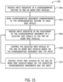
- the ride system further comprises a display system configured to provide a cinematic presentation for viewing by the rider of each ride vehicle, and a controller configured to instruct the display system to provide the cinematic presentation, and control the support actuator, the ride vehicle movement system, and the roll system of each ride vehicle of the one or more ride vehicles individually based on a choreographed routine of the one or more ride vehicles that corresponds to the cinematic presentation and an input received from a selected ride vehicle of the one or more ride vehicles, wherein the input is indicative of an adjustment to the movement of the rider support, the ride vehicle, or both, of the selected ride vehicle, and wherein the one or more ride vehicles comprise a plurality of ride vehicles, wherein the choreographed routine comprises a designation of the selected ride vehicle of the plurality of ride vehicles based at least in part on a time sequence of the choreographed routine, and wherein the selected ride vehicle is a first ride vehicle of the plurality of ride vehicles in a first time period during the time sequence, and the selected ride vehicle is a second ride vehicle
- a ride system in an embodiment comprises a track, a ride vehicle configured to travel along the track, wherein the ride vehicle comprises a plurality of rider supports, wherein each rider support of the plurality of rider supports is configured to carry a respective rider, a plurality of support actuators, wherein each support actuator of the plurality of support actuators is coupled to a respective rider support of the plurality of rider supports and a base of the ride vehicle, and each support actuator of the plurality of support actuators is configured to move the respective rider support relative to the base, a ride vehicle movement system integrated with the base and configured to move the ride vehicle along the track, and a roll system configured to move the base and the plurality of rider supports angularly relative to the track.
- the controller is configured to control movement of one or more other rider supports of the plurality of rider supports different from the selected rider support based at least in part on the input received from the selected rider support.
Landscapes
- Engineering & Computer Science (AREA)
- General Engineering & Computer Science (AREA)
- Physics & Mathematics (AREA)
- General Physics & Mathematics (AREA)
- Automation & Control Theory (AREA)
- Motorcycle And Bicycle Frame (AREA)
- Vehicle Body Suspensions (AREA)
- Traffic Control Systems (AREA)
Applications Claiming Priority (4)
| Application Number | Priority Date | Filing Date | Title |
|---|---|---|---|
| US201962865766P | 2019-06-24 | 2019-06-24 | |
| US16/456,234 US10843093B1 (en) | 2019-06-24 | 2019-06-28 | Ride systems having dynamic ride vehicle movement |
| EP20736555.2A EP3986584B1 (de) | 2019-06-24 | 2020-06-18 | Fahrsysteme mit dynamischer fahrzeugbewegung |
| PCT/US2020/038464 WO2020263679A1 (en) | 2019-06-24 | 2020-06-18 | Ride systems having dynamic ride vehicle movement |
Related Parent Applications (1)
| Application Number | Title | Priority Date | Filing Date |
|---|---|---|---|
| EP20736555.2A Division EP3986584B1 (de) | 2019-06-24 | 2020-06-18 | Fahrsysteme mit dynamischer fahrzeugbewegung |
Publications (3)
| Publication Number | Publication Date |
|---|---|
| EP4397385A2 true EP4397385A2 (de) | 2024-07-10 |
| EP4397385A3 EP4397385A3 (de) | 2024-10-09 |
| EP4397385B1 EP4397385B1 (de) | 2026-01-21 |
Family
ID=73462011
Family Applications (2)
| Application Number | Title | Priority Date | Filing Date |
|---|---|---|---|
| EP20736555.2A Active EP3986584B1 (de) | 2019-06-24 | 2020-06-18 | Fahrsysteme mit dynamischer fahrzeugbewegung |
| EP24177274.8A Active EP4397385B1 (de) | 2019-06-24 | 2020-06-18 | Fahrsysteme mit dynamischer fahrfahrzeugbewegung |
Family Applications Before (1)
| Application Number | Title | Priority Date | Filing Date |
|---|---|---|---|
| EP20736555.2A Active EP3986584B1 (de) | 2019-06-24 | 2020-06-18 | Fahrsysteme mit dynamischer fahrzeugbewegung |
Country Status (8)
| Country | Link |
|---|---|
| US (2) | US10843093B1 (de) |
| EP (2) | EP3986584B1 (de) |
| JP (2) | JP7569814B2 (de) |
| KR (2) | KR102890066B1 (de) |
| CN (1) | CN114025857B (de) |
| ES (2) | ES2989262T3 (de) |
| SG (1) | SG11202113232UA (de) |
| WO (1) | WO2020263679A1 (de) |
Families Citing this family (3)
| Publication number | Priority date | Publication date | Assignee | Title |
|---|---|---|---|---|
| US11130665B1 (en) * | 2019-08-05 | 2021-09-28 | Yuriy Karpinskyy | Mobile recreational lift system and method |
| US20240408503A1 (en) * | 2023-06-12 | 2024-12-12 | Disney Enterprises, Inc. | Rider controlled amusement park ride |
| US20260027482A1 (en) * | 2024-07-24 | 2026-01-29 | Disney Enterprises, Inc. | Ride system having an articulating arm |
Family Cites Families (20)
| Publication number | Priority date | Publication date | Assignee | Title |
|---|---|---|---|---|
| US4879849A (en) * | 1987-11-04 | 1989-11-14 | Omni Films International, Inc. | Point-of-view motion simulator system |
| US5583844A (en) * | 1993-06-19 | 1996-12-10 | The Walt Disney Company | Programming device and method for controlling ride vehicles in an amusement attraction |
| US5403238A (en) | 1993-08-19 | 1995-04-04 | The Walt Disney Company | Amusement park attraction |
| US6024647A (en) | 1998-06-24 | 2000-02-15 | Universal Studios, Inc. | Amusement ride vehicle with motion controlled seating |
| WO2001095989A1 (en) * | 2000-06-16 | 2001-12-20 | Robocoaster Limited | Ride apparatus |
| JP2006158758A (ja) | 2004-12-09 | 2006-06-22 | Seiko Epson Corp | 走行型遊具および走行型遊具システム |
| US7806054B2 (en) | 2008-05-05 | 2010-10-05 | Disney Enterprises, Inc. | Amusement park ride with vehicles pivoting about a common chassis to provide racing and other effects |
| US8388458B2 (en) * | 2010-12-29 | 2013-03-05 | Disney Enterprises, Inc. | Round ride with lateral flight |
| US8641540B2 (en) | 2011-07-13 | 2014-02-04 | Roland Feuer | Inverted simulation attraction |
| DE102011114371A1 (de) * | 2011-09-23 | 2013-03-28 | Alexander Verl | Fahrgeschäft |
| US8578857B2 (en) * | 2011-12-08 | 2013-11-12 | Disney Enterprises, Inc. | Amusement park ride with passenger loading separated from vehicle insertion into simulators |
| GB201320319D0 (en) * | 2013-11-18 | 2014-01-01 | Robocoaster Ltd | Movable screen |
| US9084941B1 (en) * | 2014-09-22 | 2015-07-21 | Eric Fram | Combination ride for amusement park |
| US9814991B2 (en) * | 2014-10-07 | 2017-11-14 | Universal City Studios Llc | Actuatable motion base system |
| US10105609B2 (en) | 2015-03-31 | 2018-10-23 | Universal City Studios Llc | System and method for positioning vehicles of an amusement park attraction |
| US9643094B2 (en) * | 2015-05-05 | 2017-05-09 | Universal City Studios Llc | Simulator ride |
| CN204601599U (zh) | 2015-05-07 | 2015-09-02 | 万达文化旅游规划研究院有限公司 | 基于机械臂式过山车的多维剧场 |
| US9610511B1 (en) | 2015-12-16 | 2017-04-04 | Disney Enterprises, Inc. | Amusement park ride vehicle including a chassis driven to have heave and sway motions |
| DE102016107239A1 (de) * | 2016-04-19 | 2017-10-19 | Simtec Systems Gmbh | Fahrgeschäft |
| CN205730323U (zh) * | 2016-05-27 | 2016-11-30 | 上海合昊机电科技有限公司 | 一种基于游乐乘骑项目的增强现实交互系统 |
-
2019
- 2019-06-28 US US16/456,234 patent/US10843093B1/en active Active
-
2020
- 2020-06-18 ES ES20736555T patent/ES2989262T3/es active Active
- 2020-06-18 SG SG11202113232UA patent/SG11202113232UA/en unknown
- 2020-06-18 JP JP2021576708A patent/JP7569814B2/ja active Active
- 2020-06-18 EP EP20736555.2A patent/EP3986584B1/de active Active
- 2020-06-18 ES ES24177274T patent/ES3064405T3/es active Active
- 2020-06-18 KR KR1020227002427A patent/KR102890066B1/ko active Active
- 2020-06-18 WO PCT/US2020/038464 patent/WO2020263679A1/en not_active Ceased
- 2020-06-18 KR KR1020257038512A patent/KR20250171390A/ko active Pending
- 2020-06-18 EP EP24177274.8A patent/EP4397385B1/de active Active
- 2020-06-18 CN CN202080046821.2A patent/CN114025857B/zh active Active
- 2020-10-15 US US17/071,732 patent/US11607620B2/en active Active
-
2024
- 2024-10-07 JP JP2024175628A patent/JP2025016492A/ja active Pending
Also Published As
| Publication number | Publication date |
|---|---|
| CN114025857B (zh) | 2024-12-03 |
| US10843093B1 (en) | 2020-11-24 |
| KR102890066B1 (ko) | 2025-11-21 |
| US11607620B2 (en) | 2023-03-21 |
| EP4397385A3 (de) | 2024-10-09 |
| JP2025016492A (ja) | 2025-02-04 |
| KR20220024911A (ko) | 2022-03-03 |
| CN114025857A (zh) | 2022-02-08 |
| US20210023465A1 (en) | 2021-01-28 |
| WO2020263679A1 (en) | 2020-12-30 |
| EP3986584B1 (de) | 2024-06-05 |
| SG11202113232UA (en) | 2021-12-30 |
| KR20250171390A (ko) | 2025-12-08 |
| JP2022539045A (ja) | 2022-09-07 |
| JP7569814B2 (ja) | 2024-10-18 |
| EP4397385B1 (de) | 2026-01-21 |
| ES3064405T3 (en) | 2026-04-24 |
| CA3141012A1 (en) | 2020-12-30 |
| EP3986584A1 (de) | 2022-04-27 |
| ES2989262T3 (es) | 2024-11-25 |
Similar Documents
| Publication | Publication Date | Title |
|---|---|---|
| US11607620B2 (en) | Ride systems having dynamic ride vehicle movement | |
| CN102309853B (zh) | 具有缆绳悬挂式载运车的游乐园乘坐装置 | |
| US11918925B2 (en) | Choreographed ride systems and methods | |
| US11439921B2 (en) | Multi-dimensional bogie and track system | |
| CA3141012C (en) | Ride systems having dynamic ride vehicle movement | |
| HK40068668A (en) | Ride systems having dynamic ride vehicle movement | |
| HK40068668B (zh) | 具有动态骑乘载具移动的骑乘系统 | |
| CN119318808A (zh) | 旋转平台滑行器 | |
| HK40120205A (zh) | 编排的乘坐系统和方法 | |
| HK40067350A (zh) | 编排的乘坐系统和方法 | |
| HK40067350B (zh) | 编排的乘坐系统和方法 |
Legal Events
| Date | Code | Title | Description |
|---|---|---|---|
| PUAI | Public reference made under article 153(3) epc to a published international application that has entered the european phase |
Free format text: ORIGINAL CODE: 0009012 |
|
| STAA | Information on the status of an ep patent application or granted ep patent |
Free format text: STATUS: THE APPLICATION HAS BEEN PUBLISHED |
|
| AC | Divisional application: reference to earlier application |
Ref document number: 3986584 Country of ref document: EP Kind code of ref document: P |
|
| AK | Designated contracting states |
Kind code of ref document: A2 Designated state(s): AL AT BE BG CH CY CZ DE DK EE ES FI FR GB GR HR HU IE IS IT LI LT LU LV MC MK MT NL NO PL PT RO RS SE SI SK SM TR |
|
| REG | Reference to a national code |
Ref country code: DE Ref legal event code: R079 Free format text: PREVIOUS MAIN CLASS: A63G0007000000 Ipc: A63G0031020000 Ref document number: 602020065736 Country of ref document: DE |
|
| PUAL | Search report despatched |
Free format text: ORIGINAL CODE: 0009013 |
|
| AK | Designated contracting states |
Kind code of ref document: A3 Designated state(s): AL AT BE BG CH CY CZ DE DK EE ES FI FR GB GR HR HU IE IS IT LI LT LU LV MC MK MT NL NO PL PT RO RS SE SI SK SM TR |
|
| RIC1 | Information provided on ipc code assigned before grant |
Ipc: A63G 33/00 20060101ALI20240830BHEP Ipc: A63G 31/16 20060101ALI20240830BHEP Ipc: A63G 31/02 20060101AFI20240830BHEP |
|
| STAA | Information on the status of an ep patent application or granted ep patent |
Free format text: STATUS: REQUEST FOR EXAMINATION WAS MADE |
|
| 17P | Request for examination filed |
Effective date: 20250403 |
|
| GRAP | Despatch of communication of intention to grant a patent |
Free format text: ORIGINAL CODE: EPIDOSNIGR1 |
|
| STAA | Information on the status of an ep patent application or granted ep patent |
Free format text: STATUS: GRANT OF PATENT IS INTENDED |
|
| INTG | Intention to grant announced |
Effective date: 20250811 |
|
| GRAS | Grant fee paid |
Free format text: ORIGINAL CODE: EPIDOSNIGR3 |
|
| GRAA | (expected) grant |
Free format text: ORIGINAL CODE: 0009210 |
|
| STAA | Information on the status of an ep patent application or granted ep patent |
Free format text: STATUS: THE PATENT HAS BEEN GRANTED |
|
| AC | Divisional application: reference to earlier application |
Ref document number: 3986584 Country of ref document: EP Kind code of ref document: P |
|
| AK | Designated contracting states |
Kind code of ref document: B1 Designated state(s): AL AT BE BG CH CY CZ DE DK EE ES FI FR GB GR HR HU IE IS IT LI LT LU LV MC MK MT NL NO PL PT RO RS SE SI SK SM TR |
|
| REG | Reference to a national code |
Ref country code: CH Ref legal event code: F10 Free format text: ST27 STATUS EVENT CODE: U-0-0-F10-F00 (AS PROVIDED BY THE NATIONAL OFFICE) Effective date: 20260121 |
|
| REG | Reference to a national code |
Ref country code: DE Ref legal event code: R096 Ref document number: 602020065736 Country of ref document: DE |
|
| REG | Reference to a national code |
Ref country code: IE Ref legal event code: FG4D |
|
| P01 | Opt-out of the competence of the unified patent court (upc) registered |
Free format text: CASE NUMBER: UPC_APP_0003222_4397385/2026 Effective date: 20260129 |
|
| REG | Reference to a national code |
Ref country code: CH Ref legal event code: R17 Free format text: ST27 STATUS EVENT CODE: U-0-0-R10-R17 (AS PROVIDED BY THE NATIONAL OFFICE) Effective date: 20260313 |
|
| REG | Reference to a national code |
Ref country code: ES Ref legal event code: FG2A Ref document number: 3064405 Country of ref document: ES Kind code of ref document: T3 Effective date: 20260424 |