EP4397358A1 - Vorrichtung zur erzeugung eines elektrischen feldes und steuerverfahren dafür sowie computerlesbares speichermedium - Google Patents
Vorrichtung zur erzeugung eines elektrischen feldes und steuerverfahren dafür sowie computerlesbares speichermedium Download PDFInfo
- Publication number
- EP4397358A1 EP4397358A1 EP22882658.2A EP22882658A EP4397358A1 EP 4397358 A1 EP4397358 A1 EP 4397358A1 EP 22882658 A EP22882658 A EP 22882658A EP 4397358 A1 EP4397358 A1 EP 4397358A1
- Authority
- EP
- European Patent Office
- Prior art keywords
- electrodes
- electrical signal
- switch units
- electric field
- electrode
- Prior art date
- Legal status (The legal status is an assumption and is not a legal conclusion. Google has not performed a legal analysis and makes no representation as to the accuracy of the status listed.)
- Granted
Links
Images







Classifications
-
- A—HUMAN NECESSITIES
- A61—MEDICAL OR VETERINARY SCIENCE; HYGIENE
- A61N—ELECTROTHERAPY; MAGNETOTHERAPY; RADIATION THERAPY; ULTRASOUND THERAPY
- A61N1/00—Electrotherapy; Circuits therefor
- A61N1/18—Applying electric currents by contact electrodes
- A61N1/32—Applying electric currents by contact electrodes alternating or intermittent currents
-
- A—HUMAN NECESSITIES
- A61—MEDICAL OR VETERINARY SCIENCE; HYGIENE
- A61N—ELECTROTHERAPY; MAGNETOTHERAPY; RADIATION THERAPY; ULTRASOUND THERAPY
- A61N1/00—Electrotherapy; Circuits therefor
- A61N1/40—Applying electric fields by inductive or capacitive coupling ; Applying radio-frequency signals
-
- A—HUMAN NECESSITIES
- A61—MEDICAL OR VETERINARY SCIENCE; HYGIENE
- A61N—ELECTROTHERAPY; MAGNETOTHERAPY; RADIATION THERAPY; ULTRASOUND THERAPY
- A61N1/00—Electrotherapy; Circuits therefor
- A61N1/18—Applying electric currents by contact electrodes
- A61N1/32—Applying electric currents by contact electrodes alternating or intermittent currents
- A61N1/36—Applying electric currents by contact electrodes alternating or intermittent currents for stimulation
- A61N1/36014—External stimulators, e.g. with patch electrodes
- A61N1/3603—Control systems
- A61N1/36034—Control systems specified by the stimulation parameters
-
- A—HUMAN NECESSITIES
- A61—MEDICAL OR VETERINARY SCIENCE; HYGIENE
- A61N—ELECTROTHERAPY; MAGNETOTHERAPY; RADIATION THERAPY; ULTRASOUND THERAPY
- A61N1/00—Electrotherapy; Circuits therefor
- A61N1/02—Details
- A61N1/025—Digital circuitry features of electrotherapy devices, e.g. memory, clocks, processors
-
- A—HUMAN NECESSITIES
- A61—MEDICAL OR VETERINARY SCIENCE; HYGIENE
- A61N—ELECTROTHERAPY; MAGNETOTHERAPY; RADIATION THERAPY; ULTRASOUND THERAPY
- A61N1/00—Electrotherapy; Circuits therefor
- A61N1/02—Details
- A61N1/04—Electrodes
- A61N1/0404—Electrodes for external use
- A61N1/0408—Use-related aspects
-
- A—HUMAN NECESSITIES
- A61—MEDICAL OR VETERINARY SCIENCE; HYGIENE
- A61N—ELECTROTHERAPY; MAGNETOTHERAPY; RADIATION THERAPY; ULTRASOUND THERAPY
- A61N1/00—Electrotherapy; Circuits therefor
- A61N1/02—Details
- A61N1/04—Electrodes
- A61N1/0404—Electrodes for external use
- A61N1/0472—Structure-related aspects
-
- A—HUMAN NECESSITIES
- A61—MEDICAL OR VETERINARY SCIENCE; HYGIENE
- A61N—ELECTROTHERAPY; MAGNETOTHERAPY; RADIATION THERAPY; ULTRASOUND THERAPY
- A61N1/00—Electrotherapy; Circuits therefor
- A61N1/02—Details
- A61N1/04—Electrodes
- A61N1/0404—Electrodes for external use
- A61N1/0472—Structure-related aspects
- A61N1/0476—Array electrodes (including any electrode arrangement with more than one electrode for at least one of the polarities)
-
- A—HUMAN NECESSITIES
- A61—MEDICAL OR VETERINARY SCIENCE; HYGIENE
- A61N—ELECTROTHERAPY; MAGNETOTHERAPY; RADIATION THERAPY; ULTRASOUND THERAPY
- A61N1/00—Electrotherapy; Circuits therefor
- A61N1/02—Details
- A61N1/04—Electrodes
- A61N1/06—Electrodes for high-frequency therapy
-
- A—HUMAN NECESSITIES
- A61—MEDICAL OR VETERINARY SCIENCE; HYGIENE
- A61N—ELECTROTHERAPY; MAGNETOTHERAPY; RADIATION THERAPY; ULTRASOUND THERAPY
- A61N1/00—Electrotherapy; Circuits therefor
- A61N1/02—Details
- A61N1/08—Arrangements or circuits for monitoring, protecting, controlling or indicating
-
- A—HUMAN NECESSITIES
- A61—MEDICAL OR VETERINARY SCIENCE; HYGIENE
- A61N—ELECTROTHERAPY; MAGNETOTHERAPY; RADIATION THERAPY; ULTRASOUND THERAPY
- A61N1/00—Electrotherapy; Circuits therefor
- A61N1/18—Applying electric currents by contact electrodes
- A61N1/32—Applying electric currents by contact electrodes alternating or intermittent currents
- A61N1/36—Applying electric currents by contact electrodes alternating or intermittent currents for stimulation
- A61N1/36002—Cancer treatment, e.g. tumour
-
- A—HUMAN NECESSITIES
- A61—MEDICAL OR VETERINARY SCIENCE; HYGIENE
- A61N—ELECTROTHERAPY; MAGNETOTHERAPY; RADIATION THERAPY; ULTRASOUND THERAPY
- A61N1/00—Electrotherapy; Circuits therefor
- A61N1/18—Applying electric currents by contact electrodes
- A61N1/32—Applying electric currents by contact electrodes alternating or intermittent currents
- A61N1/36—Applying electric currents by contact electrodes alternating or intermittent currents for stimulation
- A61N1/36014—External stimulators, e.g. with patch electrodes
- A61N1/3603—Control systems
-
- G—PHYSICS
- G16—INFORMATION AND COMMUNICATION TECHNOLOGY [ICT] SPECIALLY ADAPTED FOR SPECIFIC APPLICATION FIELDS
- G16H—HEALTHCARE INFORMATICS, i.e. INFORMATION AND COMMUNICATION TECHNOLOGY [ICT] SPECIALLY ADAPTED FOR THE HANDLING OR PROCESSING OF MEDICAL OR HEALTHCARE DATA
- G16H20/00—ICT specially adapted for therapies or health-improving plans, e.g. for handling prescriptions, for steering therapy or for monitoring patient compliance
- G16H20/40—ICT specially adapted for therapies or health-improving plans, e.g. for handling prescriptions, for steering therapy or for monitoring patient compliance relating to mechanical, radiation or invasive therapies, e.g. surgery, laser therapy, dialysis or acupuncture
Definitions
- an electrical signal generator applies a series of electrical signals to an electrode pair. Since two electrodes in the electrode pair are directly facing each other, a vertical electric field is generated between the two directly facing electrodes of the electrode pair, and the vertical electric field is applied to a target biological tissue region containing target biological tissue.
- a pair of electrodes is located at the periphery of a target biological tissue region, and target biological tissue (such as diseased cells) in the target biological tissue region is not guaranteed to be within the vertical electric field range of the pair of electrodes in the prior art, or is not located entirely within the vertical electric field range of the pair of electrodes in the prior art. That is, the coverage of the vertical electric field in the prior art is too fixed and small, so the coverage of the target biological tissue is limited, and thereby the intensity of the electric field covering a target biological tissue region is limited, and it is ineffective in inhibiting the division of such target biological tissue as diseased cells.
- the present application provides an electric field generating device, a control method for the electric field generating device, and a computer-readable storage medium, so as to solve the technical problem in the prior art that, it is ineffective in inhibiting the division of such target biological tissue as diseased cells due to the limited intensity of the electric field covering a target biological tissue region, and thereby the intensity of the electric field covering the target biological tissue is limited.
- an electric field generating device including:
- the present application provides a control method for the electric field generating device in the first aspect, including:
- it is able to flexibly select the quantity of electrodes surrounding the target biological tissue region according to a position of the target biological tissue in the target biological tissue region, and control which electrodes to be applied to the second electrical signal, so that a coverage area of the electric field generated between the electrodes with the first electrical signal and the electrodes with the second electrical signal best matches the position of the target biological tissue. Therefore, it is able to improve a matching degree between the coverage area of the electric field and the position of the target biological tissue, a coverage, and flexibility or adaptability of the electric field on the target biological tissue, thereby to increase the intensity of the electric field covering the target biological tissue, and further improve the effect of inhibiting the division of such target biological tissue as diseased cells.
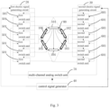
- 10-n electrodes 25-electrical signal generator, 20-first electric signal generating circuit, 30-second electric signal generating circuit, 40-control signal generator, 50-first switch assembly, 501-first switch unit, 60-second switch assembly, 601-second switch unit, 70-multi-channel analog switch unit; 80-target biological tissue region, 81-target biological tissue, 82-normal biological tissue; 91-first layer, 92-second layer, 201-first electrode array, 202-second electrode array, 203-third electrode array.
- the present application provides an electric field generating device, a control method for the electric field generating device and a computer-readable storage medium, so as to solve the technical problem in the prior art that, it is ineffective in inhibiting the division of such target biological tissue as diseased cells due to the limited intensity of the electric field covering a target biological tissue region, and thereby the intensity of the electric field covering the target biological tissue is limited.
- a pair of electrodes is located at the periphery of a target biological tissue region, and target biological tissue (such as diseased cells) in the target biological tissue region is not guaranteed to be within the vertical electric field range of the pair of electrodes in the prior art, or is not located entirely within the vertical electric field range of the pair of electrodes in the prior art. That is, the coverage of the vertical electric field in the prior art is too fixed and small, so the coverage of the target biological tissue is limited, and thereby the intensity of the electric field covering a target biological tissue region is limited, and it is ineffective in inhibiting the division of such target biological tissue as diseased cells.
- the present application provides a target electric field generating device and a control method for the electric field generating device, so as to solve the above technical problems in the prior art.
- the electric field generating device in the embodiments of the present application is for surgical use and is applicable for surgical medical instruments.
- the normal biological tissue refers to a biological tissue that does not contain diseased cells, a tumor and a lesion, and can be considered as a biological tissue other than the target biological tissue.
- the electrical signal generator 25 is electrically connected to the n electrodes 10.
- the control signal generator 40 is electrically connected to the electrical signal generator 25, and configured to control the electrical signal generator 25 to apply a first electrical signal to m electrodes of the n electrodes 10, and apply a second electrical signal to at least two electrodes of n-m electrodes, to generate an electric field between the electrodes with the first electrical signal and the electrodes with the second electrical signal, where a voltage of the second electrical signal is less than a voltage of the first electrical signal, 1 ⁇ m ⁇ n, and m is an integer.
- the first electrical signal and the second electrical signal may be outputted by one electrical signal generator, or may be outputted by two electrical signal generators respectively.
- the n electrodes 10 may be attached to a target part of a human body or an animal body according to the set manner.
- control signal generator 40 may be a central processing unit (Central Processing Unit, CPU), a general-purpose processor, a data signal processor (Digital Signal Processor, DSP), an application specific integrated circuit (Application Specific Integrated Circuit, ASIC), or a field-programmable gate array (Field-Programmable Gate Array, FPGA) or other programmable logic devices, transistor logic devices, hardware members or any combination thereof. It may implement or execute various illustrative logical blocks, modules and circuits described in connection with the content of the present application.
- the control signal generator 40 may also be a combination that implements computing functions, such as a combination of one or more microprocessors, a combination of a DSP and a microprocessor, etc.
- it is able to flexibly select the quantity of electrodes surrounding the target biological tissue region according to a position of the target biological tissue in the target biological tissue region, and control which electrodes to be applied to the second electrical signal, so that a coverage area of the electric field generated between the electrode with the first electrical signal and the electrodes with the second electrical signal best matches the position of the target biological tissue. Therefore, it is able to improve a matching degree between the coverage area of the electric field and the position of the target biological tissue, a coverage, and flexibility or adaptability of the electric field on the target biological tissue, thereby to increase the intensity of the electric field covering the target biological tissue, and further improve the effect of inhibiting the division of such target biological tissue as diseased cells.
- multiple electric fields can be generated between the electrode with the first electrical signal and at least two electrodes with the second electrical signal, and can be superimposed so as to enhance the intensity of an electric field at a superimposed region.
- at least two electrodes with the second electrical signal are selected reasonably, it is able to improve the coverage of the electric field on the target biological tissue, thereby to improve the effect of inhibiting the division of such target biological tissue as diseased cells.
- the electrical signal generator 25 includes a first electrical signal generating circuit 20 and a second electrical signal generating circuit 30.
- the first electrical signal generating circuit 20 is electrically connected to the n electrodes, and configured to output the first electrical signal.
- the second electrical signal generating circuit 30 is electrically connected to the n electrodes and configured to output the second electrical signal.
- the electric field generating device further includes a first switch assembly 50 and a second switch assembly 60.
- the first electrical signal generating circuit 20 is electrically connected to the n electrodes 10 through the first switch assembly 50, and the control signal generator 40 is electrically connected to the first switch assembly 50.
- the second electrical signal generating circuit 30 is electrically connected to the n electrodes 10 through the second switch assembly 60, and the control signal generator 40 is electrically connected to the second switch assembly 60.
- the control signal generator 40 is configured to control the first switch assembly 50 to transmit the first electrical signal to m electrodes of the n electrodes 10, and control the second switch assembly 60 to transmit the second electrical signal to at least two electrodes of n-m electrodes, to generate the electric field between the electrodes with the first electrical signal and the electrodes with the second electrical signal.
- the first switch assembly 50 includes n first switch units 501
- the second switch assembly 60 includes n second switch units 601.
- the n first switch units 501 are electrically connected to the n electrodes 10 respectively, and electrically connected to the first electrical signal generating circuit 20 and the control signal generator 40.
- the n second switch units 601 are electrically connected to the n electrodes 10 respectively, and electrically connected to the second electrical signal generating circuit 30 and the control signal generator 40.
- the n first switch units include a first one of the first switch units to an nth one of the first switch units
- the n second switch units include a first one of the second switch units to an nth one of the second switch units
- the n electrodes include a first electrode to an nth electrode.
- the electric field generating device further includes at least one of the following:
- the first electrical signal generating circuit 20 includes an alternating current signal generating circuit, a pulse electrical signal generating circuit or a square wave electrical signal generating circuit, the alternating current signal generating circuit is used to output an AC voltage signal, the pulse electrical signal generating circuit is used to output a pulse voltage signal, and the square wave electrical signal generating circuit is used to output a square wave voltage signal.
- the absolute value of the voltage amplitude of the second electrical signal is 0V, 1V or 5V
- the first electrical signal generating circuit 20 is electrically connected to six electrodes and used to apply the first electrical signal to the six electrodes.
- the second electrical signal generating circuit 30 is electrically connected to the six electrodes and used to apply the second electrical signal to the six electrodes.
- control signal generator 40 controls one of the first switch units 501 to transmit the first electrical signal to the electrode 101, and controls the remaining first switch units 501 to be turned off.
- control signal generator 40 controls one of second switch units 601 that is electrically connected to the electrode 101 to be turned off, and controls the remaining second switch units 601 to transmit the second electrical signal to the electrodes 102-106.
- the electrode 101 is controlled to have the first electrical signal
- the electrodes 102-106 are controlled to have the second electrical signal, so a first electric field is generated between the electrode 101 and the electrode 102, a second electric field is generated between the electrode 101 and the electrode 103, a third electric field is generated between the electrode 101 and the electrode 104, a fourth electric field is generated between the electrode 101 and the electrode 105, and a fifth electric field is generated between the electrode 101 and the electrode 106.
- the first electrical signal applied to the electrode 101 is controlled to be a high voltage signal (for example, between 0 and 500V), and the second electrical signal applied to the electrodes 102-106 is controlled to be a low voltage signal (for example, 0 to 10V), that is, there are multiple potential differences between the electrode 101 and the electrodes 102-106, and multiple electric fields are generated between the electrodes 101 and the electrodes 102-106, so it is able to increase the coverage area of the electric field on the patient's target region, and thereby increase the intensity of the electric field covering the patient's target region, increase the intensity of the electric field covering the target biological tissue, where the target biological tissue region includes the target biological tissue and the normal biological tissue, and improve the effect of inhibiting the division of such target biological tissue as diseased cells.
- the electrode 101 and the electrode 102 to have the first electrical signal, and the electrodes 103-106 to have the second electrical signal, or control the electrode 101 to have the first electrical signal, and the electrode 103 and the electrode 105 to have the second electrical signal, or control the electrode 101 to have the first electrical signal, and the electrode 102, the electrode 104 and the electrode 106 to have the second electrical signal, or control the electrode 101 to have the first electrical signal, and the electrode 103, the electrode 104 and the electrode 105 to have the second electrical signal, which is not particularly defined in the present application.
- a time interval for the second switch units 601 to be turned on or off sequentially according to the set order is not less than 20ms and not greater than 500ms.
- the electrodes 101-106 are applied with the first electrical signal and the second electrical signal sequentially according to the set order, which further reduces the power consumption of the electric field generating device, thereby preventing the electric field generating device from overheating.
- controlling the electrical signal generator to apply the first electrical signal to m electrodes of the n electrodes, and apply the second electrical signal to at least two electrodes of the n-m electrodes, to generate the electric field between the electrodes with the first electrical signal and the electrodes with the second electrical signal includes:
- controlling the first switch assembly to transmit the first electrical signal to m electrodes of the n electrodes, and controlling the second switch assembly to transmit the second electrical signal to at least two electrodes of the n-m electrodes, to generate the electric field between the electrodes with the first electrical signal and the electrodes with the second electrical signal includes: controlling a first one of first switch units to transmit the first electrical signal to a first electrode of n electrodes, and controlling a second one of the first switch units to a nth one of the first switch units to be turned off; simultaneously controlling a first one of second switch units that is electrically connected to the first electrode to be turned off, and controlling at least two second switch units among a second one of the second switch units to an nth one of the second switch units to transmit the second electrical signal to at least two electrodes of n electrodes except the first electrode.
- the electrode 101 and the electrode 102 to have the first electrical signal, and the electrodes 103-106 to have the second electrical signal, or control the electrode 101 to have the first electrical signal, and the electrode 103 and the electrode 105 to have the second electrical signal, or control the electrode 101 to have the first electrical signal, and the electrode 102, the electrode 104 and the electrode 106 to have the second electrical signal, or control the electrode 101 to have the first electrical signal, and the electrode 103, the electrode 104 and the electrode 105 to have the second electrical signal, which is not particularly defined in the present application.
- the first switch assembly includes n first switch units, and the second switch assembly includes n second switch units.
- the n first switch units include the first one of the first switch units to the nth one of the first switch units
- the n second switch units include the first one of the second switch units to the nth one of the second switch units
- the n electrodes include the first electrode to an nth electrode.
- the first one to the nth one of the first switch units and the first one to the nth one of the second switch units are electrically connected to n electrodes respectively, i.e., the first one of the first switch units and the first one of the second switch units are electrically connected to the first electrode, a second one of the first switch units and a second one of the second switch units are electrically connected to the second electrode, ..., the nth one of the first switch units and the nth one of the second switch units are electrically connected to the nth electrode.
- one of n electrodes is controlled to be applied with the first electrical signal continuously, and the remaining electrodes 102-106 are controlled to be applied with the second electrical signal sequentially according to the set order, where the voltage of the second electrical signal applied to the remaining electrodes 102-106 is smaller than the voltage of the first electrical signal.
- one electrode is applied with the first electrical signal, the remaining electrodes are applied with the second electrical signal, and the second electrical signal is switched among the remaining electrodes, so the power consumption is reduced, thereby reducing the power consumption of the electric field generating device.
- one of the first switch units 501 is controlled to transmit the first electrical signal to the electrode 101, and the remaining first switch units 501 are controlled to be turned off.
- one of the second switch units 601 that is electrically connected to the electrode 101 is controlled to be turned off, and the remaining second switch units 601 are synchronously controlled to be turned on sequentially according to the set order, so as to transmit the second electrical signal sequentially to the electrodes 102-106 according to the set order. That is, the electrode 101 is applied with the first electrical signal continuously, and the electrodes 102-106 are applied with the second electrical signal sequentially according to the set order (that is, the second electrical signal is switched among the electrodes 102-106 according to the set order).
- the set order includes: a clockwise order, a counterclockwise order, an n-pointed star shape order, or any other hop or non-continuous orders.
- a time interval for the second switch units 601 to be turned on or off sequentially according to the set order is not less than 20ms and not greater than 500ms.
- the electrode 101 is controlled to be applied with the first electrical signal within a first time period
- the electrode 102 is controlled to be applied with the second electrical signal within a second time period
- the electrode 103 is controlled to be applied with the second electrical signal within a third time period
- the electrode 104 is controlled to be applied with the second electrical signal within a fourth time period
- the electrode 105 is controlled to be applied with the second electrical signal within the fifth time period
- the electrode 106 is controlled to be applied with the second electrical signal within the sixth time period.
- the first time period, the second time period, the third time period, the fourth time period, the fifth time period and the sixth time period may be all the same, all different, or partially the same, and may be set according to actual situations, which is not particularly defined in the present application.
- the electrode 101 is controlled to be applied with the first electrical signal continuously, and the remaining electrodes 102-106 are controlled to be applied with the second electrical signal sequentially according to the set order, where the voltage of the second electrical signal applied to the remaining electrodes 102-106 is smaller than the voltage of the first electrical signal.
- one electrode is applied with the first electrical signal, the remaining electrodes are applied with the second electrical signal, and the second electrical signal is switched among the remaining electrodes, so the power consumption is reduced, thereby reducing the power consumption of the electric field generating device and extending the standby duration of the battery used for power supply of the electric field generating device.
- m is 1, and controlling the first switch assembly to transmit the first electrical signal to m electrodes of the n electrodes, and controlling the second switch assembly to transmit the second electrical signal to at least two electrodes of the n-m electrodes, to generate the electric field between the electrodes with the first electrical signal and the electrodes with the second electrical signal includes: controlling n first switch units to be turned on sequentially according to a set order, to enable n electrodes to receive the first electrical signal sequentially according to the set order, synchronously controlling n second switch units to be turned off sequentially according to the set order, and synchronously controlling second switch units combinations to be turned on sequentially according to the set order, to enable electrode combinations corresponding to the second switch units combinations to receive the second electrical signal sequentially according to the set order; where each second switch units combination includes at least two second switch units of n-1 second switch units that are not turned off, each electrode combination includes at least two electrodes that do not receive the first electrical signal.
- the first switch assembly includes the n first switch units
- the second switch assembly includes the n second switch units.
- first switch units 501 are controlled to be turned on sequentially according to the set order, so as to transmit the first electrical signal to the corresponding electrodes sequentially according to the set order.
- Six second switch units 601 electrically connected to the corresponding electrodes are synchronously controlled to be turned off sequentially according to the set order, and second switch units 601 that are not turned off are synchronously controlled to be turned on sequentially according to the set order, so as to transmit the second electrical signal to electrodes that do not receive the first electrical signal sequentially according to the set order.
- a time interval for the second switch units 601 to be turned on or off sequentially according to the set order is not less than 20ms and not greater than 500ms.
- a case where the target biological tissue is a tumor is taken as an example, a two-dimensional model is performed on the target biological tissue and n electrodes surrounding the target biological tissue region, and a three-dimensional model is performed on a human thorax and a tumor in the human thorax.
- a finite element modeling process is as follows.
- the conductivity of a tumor region i.e., the target biological tissue 81
- the conductivity of a surrounding normal biological tissue 82 is set to 0.11S/m and the dielectric constant thereof is set to 1980.
- first electrical signal outputted by the first electrical signal generating circuit is a high voltage signal
- second electrical signal outputted by the second electrical signal generating circuit is a low voltage signal
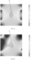
- Fig. 5a shows the case where the single electrode is grounded. After calculation, an average field strength in the tumor region is 1.6075V/cm (volts per centimeter).
- the electrode 107 is set to receive the first electrical signal (the high voltage signal) outputted by the first electrical signal generating circuit, and the electrode 108 as well as the electrode 109 are set to receive the second electrical signal (the low voltage signal) outputted by the second electrical signal generating circuit, that is, the electrode 107 receives a power source voltage, and the electrode 108 as well as the electrode 109 are grounded.
- Fig. 5b shows the case where two electrodes are grounded. After calculation, an average field strength in the tumor region is 1.6775V/cm. As compared with the case where the single electrode is grounded, the average field strength in the tumor region is increased by 4.35%.
- the electrode 107 is set to receive the first electrical signal (the high voltage signal) outputted by the first electrical signal generating circuit, and the electrode 108 as well as the electrode 110 are set to receive the second electrical signal (the low voltage signal) outputted by the second electrical signal generating circuit, that is, the electrode 107 receives a power source voltage, and the electrode 108 as well as the electrode 110 are grounded.
- Fig. 5c shows the case where two electrodes are grounded. After calculation, an average field strength in the tumor region is 1.6775V/cm. As compared with the case where the single electrode is grounded, the average field strength in the tumor region is increased by 4.35%.
- Average field strengths on the tumor in different cases are shown in Table 1.
- Table 1 Average field strengths on the tumor in different cases average field strength (V/cm) case where the single electrode is grounded 1.6075 first case where two electrodes are grounded 1.6775 second case where two electrodes are grounded 1.6775
- it is able to increase the coverage area of the electric field on the target biological tissue, increase the intensity of the electric field covering the target biological tissue region, and thereby increase the intensity of the electric field covering the target biological tissue, and improve the effect of inhibiting the division of such target biological tissue as diseased cells.
- a finite element modeling process is as follows.
- a human thorax Construction of a human thorax. Approximate shapes of actual tissues are constructed in Rhino3D NURBS 7, and compared with multiple (Computed Tomography, CT) scanning, slices, so as to modify boundary contours, thereby ultimately restoring a realistic human body model.
- the modeling content includes skin, fat, muscles, bones, lungs, heart and liver. Some over-detailed tissues (such as connective tissues, pleurae) that have similar electrical parameters and are difficult to model are merged into muscle tissues. A final model is shown in Fig. 6 .
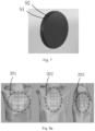
- Each electrode is modeled as a double-layer structure as shown in Fig, 7 (i.e., a first layer 91 and a second layer 92 in Fig. 7 ), in which a layer having a large area (the first layer 91 in Fig. 7 ) that is close to a skin is a gel layer with a diameter of 21mm and a thickness ranging from 0.5 mm to 2mm, a layer having a small area (the second layer 92 in Fig. 7 ) is an insulation layer with a diameter of 20mm and a thickness of 1mm.
- the insulation layer is made of a ceramic material with high dielectric constant. The dielectric constant is close to 10,000. The electric field is transmitted to the human body through the ceramic layer and gel layer.
- the electrode array is composed of multiple electrodes. For example, 5 electrodes, 10 electrodes, 15 electrodes, and other quantities of electrodes may form multiple different electrode arrays.
- Fig. 8a and Fig. 8b show the distribution of the electrode arrays applicable for human thoracic lung cancer treatment, where Fig. 8a shows the layout of an initial electrode array.
- electrode arrays applicable for lung cancer treatment are categorized into three types, namely, a front electrode array (a first electrode array 201 located on the front side of the thorax of a human body in Fig. 8a ), a back electrode array (a first electrode array 202 located on the back of the human body in Fig. 8a ) and a side electrode array (a third electrode array 203 located on one side of the human body in Fig. 8a ).
- the front electrode array and the back electrode array each include more electrodes, for example, the front electrode array (i.e., the first electrode array 201) and the back electrode array (i.e., the second electrode array 202) each include 20 electrodes.
- the electrode arrays positioned laterally each include fewer electrodes.
- the third electrode array 203 including 13 electrodes is placed on each side of the human body. As shown in Fig.
- the first electrode array 201 is arranged on the front side of the thorax of the human body
- the second electrode array 202 is arranged on the back of the human body
- the third electrode array 203 is arranged on a left side of the human body
- the third electrode array 203 is arranged on a right side of the human body. That is, four electrode arrays (i.e., the first electrode array 201, the second electrode array 202, the third electrode array 203 and the third electrode array 203) are arranged on the front side of the thorax, back, left side, and right side of the human body.
- Tumor T1 in a middle lobe of a right lung has a diameter of 40mm.
- Tumor T2 is in a middle lobe of the right lung.
- Tumor T3 is in a middle lobe of a left lung.
- Tumor T4 is in a lower lobe of a left lung.
- Tumors T2, T3 and T4 each have a diameter of 60mm.
- Frequency domain simulation is used, a frequency thereof is set to 150kHz, and a normal current density on each electrode is set to 100mA/cm 2 (milliamps per square centimeter).
- Field strength evaluation method COMSOL is used to calculate a curve diagram between the electric field strength-volume (EVH) at the tumor, as shown in Fig. 10 , where a horizontal axis is the field strength (V/cm), and a vertical axis is a volume ratio of the tumor (%). Each point on the curve represents a volume ratio of the tumor that is greater than a field strength value corresponding to the point.
- An area below the entire curve is used to represent the field strength coverage on the tumor, and the area can be obtained by integrating the curve. A value of the area is referred to as EAUC (Electric Field Area Under Curve).
- first electrical signal outputted by the first electrical signal generating circuit is a high voltage signal
- second electrical signal outputted by the second electrical signal generating circuit is a low voltage signal
- the front electrode array is set as a power source receiving end, and configured to receive the first electric signal outputted by the first signal generation circuit
- the back electrode array, the left side electrode array and the right side electrode array are set as ground ends, and configured to receive the second electric signal outputted by the second signal generation circuit.
- the E AUC value in the case where two electrode arrays are grounded is higher than the E AUC value in the case where the single electrode array is grounded, i.e., the E AUC value is increased. It can be observed from Table 3 that, for Tumor T1, the E AUC value in the case where two electrode arrays are grounded, as compared with the case where the single electrode array is grounded, is increased by 1.22%. For Tumor T2, the E AUC value in the case where two electrode arrays are grounded, as compared with the case where the single electrode array is grounded, is increased by 1.23%.
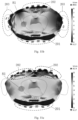
- Fig. 11a and Fig. 11b The distribution of the electric field in a horizontal plane of the thorax including Tumor T1 is shown in Fig. 11a and Fig. 11b , where a position of Tumor T1 is selected at the center of a tumor sphere. It may be observed from the figures that the intensity of the electric field located on the left side of the human body in Fig. 11b (e.g., a left part of Fig. 11b ) is higher as compared with that on the left side of the human body in Fig. 11a .
- Fig. 12a and Fig. 12b The distribution of the electric field in a horizontal plane of the thorax including Tumor T2 is shown in Fig. 12a and Fig. 12b , where a position of Tumor T2 is selected at the center of a tumor sphere. It may be observed from the figures that the intensity of the electric field located on the left side of the human body in Fig. 12b (e.g., a left part in the figure) is higher as compared with that on the left side in Fig. 12a .
- the E AUC value in the case where two electrode arrays are grounded is higher than the E AUC value in the case where the single electrode array is grounded, i.e., the E AUC value is increased. It can be observed from Table 3 that, for Tumor T3, the E AUC value in the case where two electrode arrays are grounded, as compared with the case where the single electrode array is grounded, is increased by 16.20%. For Tumor T4, the E AUC value in the case where two electrode arrays are grounded, as compared with the case where the single electrode array is grounded, is increased by 15.79%.
- Fig. 13a and Fig. 13b The distribution of the electric field in a horizontal plane of the thorax including Tumor T3 is shown in Fig. 13a and Fig. 13b , where a position of Tumor T3 is selected at the center of a tumor sphere. It may be observed from the figures that the intensity of the electric field located on the right side of the human body in Fig. 13b (e.g., a right part in the figure) is higher as compared with that on the right side of the human body in Fig. 13a .
- Fig. 14a and Fig. 14b The distribution of the electric field in a horizontal plane of the thorax including Tumor T4 is shown in Fig. 14a and Fig. 14b , where a position of Tumor T4 is selected at the center of a tumor sphere. It may be observed from the figures that the intensity of the electric field located on the right side of the human body in Fig. 14b (e.g., a right part in the figure) is higher as compared with that on the right side of the human body in Fig. 14a .
- Table 4 E AUC values at Tumor T3 and Tumor T4 in different cases E ACU (V/cm) Tumor T3 T4 case where the single electrode array (the back electrode array) is grounded 1.79 2.09 case where two electrode arrays (the back electrode array and the left side electrode array) are grounded 2.08 2.42
- Fig. 13a and Fig. 13c The distribution of the electric field in a horizontal plane of the thorax including Tumor T3 is shown in Fig. 13a and Fig. 13c , where a position of Tumor T3 is selected at the center of a tumor sphere. It may be observed from the figures that the intensity of the electric field located on the back of the human body in Fig. 13c (e.g., in an upper part of Fig. 13c ) is higher as compared with the intensity of the electric field in the upper part of Fig. 13a .
- Table 5 E AUC values at Tumor T1, Tumor T2, Tumor T3 and Tumor T4 in different cases EACU (V/cm) Tumor T1 T2 T3 T4 case where the single electrode array (the back electrode array) is grounded 2.43 2.45 1.79 2.09 case where two electrode arrays (two electrode arrays on the back) are grounded 2.53 2.56 2.06 2.29
- steps, measures and schemes in various operations, methods and processes that have already been discussed in the embodiments of the present application may be replaced, modified, combined or deleted.
- the other steps, measures and schemes in various operations, methods and processes that have already been discussed in the embodiments of the present application may also be replaced, modified, rearranged, decomposed, combined or deleted.
- steps, measures and schemes in various operations, methods and processes that are known in the related art and have already been discussed in the embodiments of the present application may also be replaced, modified, rearranged, decomposed, combined or deleted.
Landscapes
- Health & Medical Sciences (AREA)
- Life Sciences & Earth Sciences (AREA)
- Engineering & Computer Science (AREA)
- Nuclear Medicine, Radiotherapy & Molecular Imaging (AREA)
- General Health & Medical Sciences (AREA)
- Public Health (AREA)
- Biomedical Technology (AREA)
- Radiology & Medical Imaging (AREA)
- Animal Behavior & Ethology (AREA)
- Veterinary Medicine (AREA)
- Heart & Thoracic Surgery (AREA)
- Hospice & Palliative Care (AREA)
- Biophysics (AREA)
- Oncology (AREA)
- Neurology (AREA)
- Surgery (AREA)
- Urology & Nephrology (AREA)
- Epidemiology (AREA)
- Medical Informatics (AREA)
- Primary Health Care (AREA)
- Electrotherapy Devices (AREA)
Applications Claiming Priority (2)
| Application Number | Priority Date | Filing Date | Title |
|---|---|---|---|
| CN202111231292.6A CN113663215B (zh) | 2021-10-22 | 2021-10-22 | 电场发生装置及其控制方法、计算机可读存储介质 |
| PCT/CN2022/124124 WO2023066048A1 (zh) | 2021-10-22 | 2022-10-09 | 电场发生装置及其控制方法、计算机可读存储介质 |
Publications (4)
| Publication Number | Publication Date |
|---|---|
| EP4397358A1 true EP4397358A1 (de) | 2024-07-10 |
| EP4397358A4 EP4397358A4 (de) | 2024-10-16 |
| EP4397358B1 EP4397358B1 (de) | 2025-04-30 |
| EP4397358C0 EP4397358C0 (de) | 2025-04-30 |
Family
ID=78550820
Family Applications (1)
| Application Number | Title | Priority Date | Filing Date |
|---|---|---|---|
| EP22882658.2A Active EP4397358B1 (de) | 2021-10-22 | 2022-10-09 | Vorrichtung zur erzeugung eines elektrischen feldes und steuerverfahren dafür sowie computerlesbares speichermedium |
Country Status (6)
| Country | Link |
|---|---|
| US (1) | US20240245912A1 (de) |
| EP (1) | EP4397358B1 (de) |
| JP (1) | JP7783470B2 (de) |
| KR (1) | KR20240060830A (de) |
| CN (1) | CN113663215B (de) |
| WO (1) | WO2023066048A1 (de) |
Families Citing this family (4)
| Publication number | Priority date | Publication date | Assignee | Title |
|---|---|---|---|---|
| CN113663215B (zh) * | 2021-10-22 | 2022-01-21 | 杭州维纳安可医疗科技有限责任公司 | 电场发生装置及其控制方法、计算机可读存储介质 |
| CN114534091B (zh) * | 2022-02-17 | 2022-09-09 | 湖南安泰康成生物科技有限公司 | 利用电场抑制肿瘤增殖的设备及其控制装置 |
| CN115671553A (zh) * | 2022-10-14 | 2023-02-03 | 上海美生医疗器械有限公司 | 用于ttf电极的高场强控制方法、装置及温度监控方法 |
| CN116585610B (zh) * | 2023-03-31 | 2024-10-29 | 湖南安泰康成生物科技有限公司 | 一种能覆盖幕下的穿戴式电极装置 |
Family Cites Families (22)
| Publication number | Priority date | Publication date | Assignee | Title |
|---|---|---|---|---|
| US5873849A (en) | 1997-04-24 | 1999-02-23 | Ichor Medical Systems, Inc. | Electrodes and electrode arrays for generating electroporation inducing electrical fields |
| US8565867B2 (en) * | 2005-01-28 | 2013-10-22 | Cyberonics, Inc. | Changeable electrode polarity stimulation by an implantable medical device |
| JP4210953B2 (ja) * | 2006-04-14 | 2009-01-21 | ソニー株式会社 | 電界制御装置及び検出装置 |
| CN101820947A (zh) | 2007-08-14 | 2010-09-01 | 诺沃库勒有限公司 | 用电场治疗寄生物 |
| US20170049513A1 (en) * | 2009-11-06 | 2017-02-23 | Cosman Medical, Inc. | Multiple electrode generator |
| US9526911B1 (en) | 2010-04-27 | 2016-12-27 | Lazure Scientific, Inc. | Immune mediated cancer cell destruction, systems and methods |
| EP2825253A1 (de) * | 2012-03-16 | 2015-01-21 | Boston Scientific Neuromodulation Corporation | Feldverstärkte stromsteuerung mit spannungsquellen |
| EP2968938B1 (de) * | 2013-03-15 | 2019-06-26 | Myndtec Inc. | Elektrisches stimulationssystem mit impulssteuerung |
| WO2017141257A1 (en) * | 2016-02-21 | 2017-08-24 | Tech Innosphere Engineering Ltd. | Noninvasive electric brain stimulation system |
| CN207477801U (zh) * | 2017-03-24 | 2018-06-12 | 长沙普特斯科技有限公司 | 一种采用调幅电场治疗肿瘤的装置 |
| CN106823145A (zh) * | 2017-03-24 | 2017-06-13 | 长沙普特斯科技有限公司 | 一种采用调幅电场治疗肿瘤的装置 |
| CN109432601A (zh) * | 2017-10-20 | 2019-03-08 | 湖南安泰康成生物科技有限公司 | 用于破坏和抑制患者体内病变组织快速生长的设备 |
| KR102104961B1 (ko) | 2018-07-03 | 2020-04-27 | 고려대학교산학협력단 | 최적화 알고리즘을 이용한 전기장 암치료장치 |
| CN108939292B (zh) * | 2018-07-23 | 2024-03-29 | 中国人民解放军第四军医大学 | 一种生物组织时域干涉电刺激装置及其使用方法 |
| IT201800009240A1 (it) * | 2018-10-08 | 2020-04-08 | We Care Thecnologies Srl | Apparecchiatura di elettrostimolazione |
| CN112618951A (zh) * | 2019-09-24 | 2021-04-09 | 上海微创医疗器械(集团)有限公司 | 一种电刺激信号发生器、电刺激系统及控制电极的方法 |
| US12491373B2 (en) * | 2020-01-17 | 2025-12-09 | London Health Sciences Centre Research Inc. | Planning and delivery of dynamically oriented electric field for biomedical applications |
| CN113018682A (zh) * | 2021-02-25 | 2021-06-25 | 杭州维那泰克医疗科技有限责任公司 | 细胞分裂抑制装置及其控制方法、装置、系统、存储介质 |
| CN113082519B (zh) * | 2021-04-30 | 2024-08-06 | 杭州维纳安可医疗科技有限责任公司 | 用于破坏或者抑制病变细胞分裂的装置及其控制方法 |
| CN113476746A (zh) * | 2021-07-20 | 2021-10-08 | 杭州维纳安可医疗科技有限责任公司 | 抑制病变细胞分裂的设备、控制方法及控制装置 |
| CN113599703A (zh) * | 2021-07-30 | 2021-11-05 | 杭州维纳安可医疗科技有限责任公司 | 电场发生装置及其控制方法 |
| CN113663215B (zh) * | 2021-10-22 | 2022-01-21 | 杭州维纳安可医疗科技有限责任公司 | 电场发生装置及其控制方法、计算机可读存储介质 |
-
2021
- 2021-10-22 CN CN202111231292.6A patent/CN113663215B/zh active Active
-
2022
- 2022-10-09 EP EP22882658.2A patent/EP4397358B1/de active Active
- 2022-10-09 WO PCT/CN2022/124124 patent/WO2023066048A1/zh not_active Ceased
- 2022-10-09 KR KR1020247013020A patent/KR20240060830A/ko active Pending
- 2022-10-09 JP JP2024522009A patent/JP7783470B2/ja active Active
-
2024
- 2024-03-01 US US18/592,976 patent/US20240245912A1/en active Pending
Also Published As
| Publication number | Publication date |
|---|---|
| WO2023066048A1 (zh) | 2023-04-27 |
| EP4397358B1 (de) | 2025-04-30 |
| JP7783470B2 (ja) | 2025-12-10 |
| US20240245912A1 (en) | 2024-07-25 |
| CN113663215A (zh) | 2021-11-19 |
| EP4397358A4 (de) | 2024-10-16 |
| CN113663215B (zh) | 2022-01-21 |
| KR20240060830A (ko) | 2024-05-08 |
| EP4397358C0 (de) | 2025-04-30 |
| JP2024535582A (ja) | 2024-09-30 |
Similar Documents
| Publication | Publication Date | Title |
|---|---|---|
| EP4397358B1 (de) | Vorrichtung zur erzeugung eines elektrischen feldes und steuerverfahren dafür sowie computerlesbares speichermedium | |
| US11779758B2 (en) | Apparatus and method of non-invasive directional tissue treatment | |
| US11701161B2 (en) | Optimizing treatment using TTFields by changing the frequency during the course of long term tumor treatment | |
| Sano et al. | Burst and continuous high frequency irreversible electroporation protocols evaluated in a 3D tumor model | |
| EP2994045B1 (de) | Vorrichtung zur behandlung eines tumors mit einem elektrischen wechselfeld und zur auswahl einer behandlungsfrequenz auf basis einer geschätzten zellgrösse | |
| Huang et al. | Can transcranial electric stimulation with multiple electrodes reach deep targets? | |
| JP2021531090A (ja) | 交流電界生成を使用した癌腫治療のためのシステム及び方法 | |
| Šemrov et al. | Calculation of the electrical parameters in electrochemotherapy of solid tumours in mice | |
| EP3294405A1 (de) | Vorrichtung und verfahren zur nichtinvasiven gerichteten gewebebehandlung unter verwendung von hochfrequenzenergie | |
| KR20190114906A (ko) | 미용에 사용하는 복합 전극패드를 이용한 미용기기와 그 방법 | |
| CN101160152A (zh) | 电磁治疗感应装置和方法 | |
| US20240335660A1 (en) | Electrical applicators with non-penetrating electrodes for applying energy to tissue surfaces | |
| US20240261585A1 (en) | Method and system for optimizing electrode array structure in electrotherapy | |
| US20250018209A1 (en) | Apparatuses, methods, and systems for treating spinal tumors with tumor treating fields | |
| Kinzel et al. | Comprehensive approaches to increasing Tumor Treating Fields (TTFields) dose at the tumor | |
| WO2025012879A1 (en) | Apparatuses, methods, and systems for treating spinal tumors with tumor treating fields | |
| HK40042528B (en) | Apparatus for treating a tumor with an alternating electric field and for selecting a treatment frequency based on estimated cell size | |
| WO2024079719A1 (en) | Method and apparatus for delivering alternating electric fields to a target tissue | |
| EP4572840A1 (de) | Verfahren und vorrichtung zur abgabe von elektrischen wechselfeldern an ein zielgewebe | |
| HK40042528A (en) | Apparatus for treating a tumor with an alternating electric field and for selecting a treatment frequency based on estimated cell size | |
| HK40017598A (en) | Apparatus for treating a tumor with an alternating electric field and for selecting a treatment frequency based on estimated cell size | |
| HK40017598B (en) | Apparatus for treating a tumor with an alternating electric field and for selecting a treatment frequency based on estimated cell size | |
| Channel et al. | 2025 PEMF Buyers Guide-Abridged Version | |
| HK1216596B (en) | Apparatus for treating a tumor with an alternating electric field and for selecting a treatment frequency based on estimated cell size |
Legal Events
| Date | Code | Title | Description |
|---|---|---|---|
| STAA | Information on the status of an ep patent application or granted ep patent |
Free format text: STATUS: THE INTERNATIONAL PUBLICATION HAS BEEN MADE |
|
| PUAI | Public reference made under article 153(3) epc to a published international application that has entered the european phase |
Free format text: ORIGINAL CODE: 0009012 |
|
| STAA | Information on the status of an ep patent application or granted ep patent |
Free format text: STATUS: REQUEST FOR EXAMINATION WAS MADE |
|
| 17P | Request for examination filed |
Effective date: 20240402 |
|
| AK | Designated contracting states |
Kind code of ref document: A1 Designated state(s): AL AT BE BG CH CY CZ DE DK EE ES FI FR GB GR HR HU IE IS IT LI LT LU LV MC ME MK MT NL NO PL PT RO RS SE SI SK SM TR |
|
| A4 | Supplementary search report drawn up and despatched |
Effective date: 20240918 |
|
| RIC1 | Information provided on ipc code assigned before grant |
Ipc: A61N 1/02 20060101ALI20240912BHEP Ipc: A61N 1/36 20060101ALI20240912BHEP Ipc: A61N 1/06 20060101ALI20240912BHEP Ipc: A61N 1/32 20060101AFI20240912BHEP |
|
| GRAP | Despatch of communication of intention to grant a patent |
Free format text: ORIGINAL CODE: EPIDOSNIGR1 |
|
| STAA | Information on the status of an ep patent application or granted ep patent |
Free format text: STATUS: GRANT OF PATENT IS INTENDED |
|
| DAV | Request for validation of the european patent (deleted) | ||
| DAX | Request for extension of the european patent (deleted) | ||
| INTG | Intention to grant announced |
Effective date: 20250114 |
|
| GRAS | Grant fee paid |
Free format text: ORIGINAL CODE: EPIDOSNIGR3 |
|
| GRAA | (expected) grant |
Free format text: ORIGINAL CODE: 0009210 |
|
| STAA | Information on the status of an ep patent application or granted ep patent |
Free format text: STATUS: THE PATENT HAS BEEN GRANTED |
|
| AK | Designated contracting states |
Kind code of ref document: B1 Designated state(s): AL AT BE BG CH CY CZ DE DK EE ES FI FR GB GR HR HU IE IS IT LI LT LU LV MC ME MK MT NL NO PL PT RO RS SE SI SK SM TR |
|
| REG | Reference to a national code |
Ref country code: CH Ref legal event code: EP Ref country code: GB Ref legal event code: FG4D |
|
| REG | Reference to a national code |
Ref country code: DE Ref legal event code: R096 Ref document number: 602022014043 Country of ref document: DE |
|
| REG | Reference to a national code |
Ref country code: IE Ref legal event code: FG4D |
|
| U01 | Request for unitary effect filed |
Effective date: 20250505 |
|
| U07 | Unitary effect registered |
Designated state(s): AT BE BG DE DK EE FI FR IT LT LU LV MT NL PT RO SE SI Effective date: 20250509 |
|
| PG25 | Lapsed in a contracting state [announced via postgrant information from national office to epo] |
Ref country code: ES Free format text: LAPSE BECAUSE OF FAILURE TO SUBMIT A TRANSLATION OF THE DESCRIPTION OR TO PAY THE FEE WITHIN THE PRESCRIBED TIME-LIMIT Effective date: 20250430 |
|
| PG25 | Lapsed in a contracting state [announced via postgrant information from national office to epo] |
Ref country code: NO Free format text: LAPSE BECAUSE OF FAILURE TO SUBMIT A TRANSLATION OF THE DESCRIPTION OR TO PAY THE FEE WITHIN THE PRESCRIBED TIME-LIMIT Effective date: 20250730 Ref country code: GR Free format text: LAPSE BECAUSE OF FAILURE TO SUBMIT A TRANSLATION OF THE DESCRIPTION OR TO PAY THE FEE WITHIN THE PRESCRIBED TIME-LIMIT Effective date: 20250731 |
|
| PG25 | Lapsed in a contracting state [announced via postgrant information from national office to epo] |
Ref country code: PL Free format text: LAPSE BECAUSE OF FAILURE TO SUBMIT A TRANSLATION OF THE DESCRIPTION OR TO PAY THE FEE WITHIN THE PRESCRIBED TIME-LIMIT Effective date: 20250430 |
|
| PG25 | Lapsed in a contracting state [announced via postgrant information from national office to epo] |
Ref country code: HR Free format text: LAPSE BECAUSE OF FAILURE TO SUBMIT A TRANSLATION OF THE DESCRIPTION OR TO PAY THE FEE WITHIN THE PRESCRIBED TIME-LIMIT Effective date: 20250430 |
|
| PG25 | Lapsed in a contracting state [announced via postgrant information from national office to epo] |
Ref country code: RS Free format text: LAPSE BECAUSE OF FAILURE TO SUBMIT A TRANSLATION OF THE DESCRIPTION OR TO PAY THE FEE WITHIN THE PRESCRIBED TIME-LIMIT Effective date: 20250731 |
|
| PG25 | Lapsed in a contracting state [announced via postgrant information from national office to epo] |
Ref country code: IS Free format text: LAPSE BECAUSE OF FAILURE TO SUBMIT A TRANSLATION OF THE DESCRIPTION OR TO PAY THE FEE WITHIN THE PRESCRIBED TIME-LIMIT Effective date: 20250830 |
|
| U20 | Renewal fee for the european patent with unitary effect paid |
Year of fee payment: 4 Effective date: 20251021 |
|
| PG25 | Lapsed in a contracting state [announced via postgrant information from national office to epo] |
Ref country code: SM Free format text: LAPSE BECAUSE OF FAILURE TO SUBMIT A TRANSLATION OF THE DESCRIPTION OR TO PAY THE FEE WITHIN THE PRESCRIBED TIME-LIMIT Effective date: 20250430 |
|
| PG25 | Lapsed in a contracting state [announced via postgrant information from national office to epo] |
Ref country code: CZ Free format text: LAPSE BECAUSE OF FAILURE TO SUBMIT A TRANSLATION OF THE DESCRIPTION OR TO PAY THE FEE WITHIN THE PRESCRIBED TIME-LIMIT Effective date: 20250430 |
|
| PG25 | Lapsed in a contracting state [announced via postgrant information from national office to epo] |
Ref country code: SK Free format text: LAPSE BECAUSE OF FAILURE TO SUBMIT A TRANSLATION OF THE DESCRIPTION OR TO PAY THE FEE WITHIN THE PRESCRIBED TIME-LIMIT Effective date: 20250430 |
|
| PLBE | No opposition filed within time limit |
Free format text: ORIGINAL CODE: 0009261 |
|
| STAA | Information on the status of an ep patent application or granted ep patent |
Free format text: STATUS: NO OPPOSITION FILED WITHIN TIME LIMIT |
|
| REG | Reference to a national code |
Ref country code: CH Ref legal event code: L10 Free format text: ST27 STATUS EVENT CODE: U-0-0-L10-L00 (AS PROVIDED BY THE NATIONAL OFFICE) Effective date: 20260311 |
|
| 26N | No opposition filed |
Effective date: 20260202 |