EP4396500B1 - Ein verfahren zum betrieb eines hvac-systems - Google Patents
Ein verfahren zum betrieb eines hvac-systems Download PDFInfo
- Publication number
- EP4396500B1 EP4396500B1 EP22768691.2A EP22768691A EP4396500B1 EP 4396500 B1 EP4396500 B1 EP 4396500B1 EP 22768691 A EP22768691 A EP 22768691A EP 4396500 B1 EP4396500 B1 EP 4396500B1
- Authority
- EP
- European Patent Office
- Prior art keywords
- thermal energy
- fluid
- flow rate
- transfer device
- energy transfer
- Prior art date
- Legal status (The legal status is an assumption and is not a legal conclusion. Google has not performed a legal analysis and makes no representation as to the accuracy of the status listed.)
- Active
Links
Images


Classifications
-
- F—MECHANICAL ENGINEERING; LIGHTING; HEATING; WEAPONS; BLASTING
- F24—HEATING; RANGES; VENTILATING
- F24F—AIR-CONDITIONING; AIR-HUMIDIFICATION; VENTILATION; USE OF AIR CURRENTS FOR SCREENING
- F24F11/00—Control or safety arrangements
- F24F11/62—Control or safety arrangements characterised by the type of control or by internal processing, e.g. using fuzzy logic, adaptive control or estimation of values
-
- F—MECHANICAL ENGINEERING; LIGHTING; HEATING; WEAPONS; BLASTING
- F24—HEATING; RANGES; VENTILATING
- F24D—DOMESTIC- OR SPACE-HEATING SYSTEMS, e.g. CENTRAL HEATING SYSTEMS; DOMESTIC HOT-WATER SUPPLY SYSTEMS; ELEMENTS OR COMPONENTS THEREFOR
- F24D19/00—Details
- F24D19/10—Arrangement or mounting of control or safety devices
- F24D19/1006—Arrangement or mounting of control or safety devices for water heating systems
- F24D19/1009—Arrangement or mounting of control or safety devices for water heating systems for central heating
- F24D19/1015—Arrangement or mounting of control or safety devices for water heating systems for central heating using a valve or valves
-
- F—MECHANICAL ENGINEERING; LIGHTING; HEATING; WEAPONS; BLASTING
- F24—HEATING; RANGES; VENTILATING
- F24D—DOMESTIC- OR SPACE-HEATING SYSTEMS, e.g. CENTRAL HEATING SYSTEMS; DOMESTIC HOT-WATER SUPPLY SYSTEMS; ELEMENTS OR COMPONENTS THEREFOR
- F24D19/00—Details
- F24D19/10—Arrangement or mounting of control or safety devices
- F24D19/1084—Arrangement or mounting of control or safety devices for air heating systems
-
- F—MECHANICAL ENGINEERING; LIGHTING; HEATING; WEAPONS; BLASTING
- F24—HEATING; RANGES; VENTILATING
- F24F—AIR-CONDITIONING; AIR-HUMIDIFICATION; VENTILATION; USE OF AIR CURRENTS FOR SCREENING
- F24F11/00—Control or safety arrangements
- F24F11/70—Control systems characterised by their outputs; Constructional details thereof
- F24F11/72—Control systems characterised by their outputs; Constructional details thereof for controlling the supply of treated air, e.g. its pressure
- F24F11/74—Control systems characterised by their outputs; Constructional details thereof for controlling the supply of treated air, e.g. its pressure for controlling air flow rate or air velocity
-
- F—MECHANICAL ENGINEERING; LIGHTING; HEATING; WEAPONS; BLASTING
- F24—HEATING; RANGES; VENTILATING
- F24F—AIR-CONDITIONING; AIR-HUMIDIFICATION; VENTILATION; USE OF AIR CURRENTS FOR SCREENING
- F24F11/00—Control or safety arrangements
- F24F11/70—Control systems characterised by their outputs; Constructional details thereof
- F24F11/80—Control systems characterised by their outputs; Constructional details thereof for controlling the temperature of the supplied air
- F24F11/83—Control systems characterised by their outputs; Constructional details thereof for controlling the temperature of the supplied air by controlling the supply of heat-exchange fluids to heat-exchangers
- F24F11/84—Control systems characterised by their outputs; Constructional details thereof for controlling the temperature of the supplied air by controlling the supply of heat-exchange fluids to heat-exchangers using valves
-
- F—MECHANICAL ENGINEERING; LIGHTING; HEATING; WEAPONS; BLASTING
- F24—HEATING; RANGES; VENTILATING
- F24D—DOMESTIC- OR SPACE-HEATING SYSTEMS, e.g. CENTRAL HEATING SYSTEMS; DOMESTIC HOT-WATER SUPPLY SYSTEMS; ELEMENTS OR COMPONENTS THEREFOR
- F24D10/00—District heating systems
-
- F—MECHANICAL ENGINEERING; LIGHTING; HEATING; WEAPONS; BLASTING
- F24—HEATING; RANGES; VENTILATING
- F24F—AIR-CONDITIONING; AIR-HUMIDIFICATION; VENTILATION; USE OF AIR CURRENTS FOR SCREENING
- F24F2140/00—Control inputs relating to system states
- F24F2140/20—Heat-exchange fluid temperature
-
- F—MECHANICAL ENGINEERING; LIGHTING; HEATING; WEAPONS; BLASTING
- F24—HEATING; RANGES; VENTILATING
- F24F—AIR-CONDITIONING; AIR-HUMIDIFICATION; VENTILATION; USE OF AIR CURRENTS FOR SCREENING
- F24F2140/00—Control inputs relating to system states
- F24F2140/50—Load
-
- F—MECHANICAL ENGINEERING; LIGHTING; HEATING; WEAPONS; BLASTING
- F24—HEATING; RANGES; VENTILATING
- F24F—AIR-CONDITIONING; AIR-HUMIDIFICATION; VENTILATION; USE OF AIR CURRENTS FOR SCREENING
- F24F2221/00—Details or features not otherwise provided for
-
- F—MECHANICAL ENGINEERING; LIGHTING; HEATING; WEAPONS; BLASTING
- F24—HEATING; RANGES; VENTILATING
- F24F—AIR-CONDITIONING; AIR-HUMIDIFICATION; VENTILATION; USE OF AIR CURRENTS FOR SCREENING
- F24F2221/00—Details or features not otherwise provided for
- F24F2221/34—Heater, e.g. gas burner, electric air heater
-
- F—MECHANICAL ENGINEERING; LIGHTING; HEATING; WEAPONS; BLASTING
- F24—HEATING; RANGES; VENTILATING
- F24F—AIR-CONDITIONING; AIR-HUMIDIFICATION; VENTILATION; USE OF AIR CURRENTS FOR SCREENING
- F24F2221/00—Details or features not otherwise provided for
- F24F2221/54—Heating and cooling, simultaneously or alternatively
Definitions
- the present invention relates to a method of operating an HVAC system comprising a thermal energy source and a thermal energy transfer device using a flow regulating device arranged to regulate a flow rate of a fluid between the thermal energy source and the thermal energy transfer device.
- the present invention further relates a flow regulating device.
- the present invention further relates to an HVAC system comprising a thermal energy source; a thermal energy transfer device; a fluid transportation system and a flow regulating device.
- the present invention even further relates to a computer program product for operating an HVAC system.
- HVAC systems typically comprise a fluid transportation system connected to a heat exchanger arranged such as to be able to transfer thermal energy to or from the environment to be controlled (referred to hereafter as controlled environment) by means of a fluid circulating in said fluid transportation system.
- thermal networks are known for enabling transfer of thermal energy from a (potentially shared) thermal energy source to one or more controlled environment(s), such as district heating, district cooling and low temperature networks.
- controlled environment(s) such as district heating, district cooling and low temperature networks.
- thermal networks are known for enabling transfer of thermal energy from one or more controlled environment(s), whereby the controlled environment(s) act as an energy source, for example by capturing thermal energy as a by-product of an industrial process.
- the fluid circulating in the fluid transportation system is typically characterized by high supply temperatures (e.g. between 60 and 130°C) from the thermal energy source, a thermal energy transfer device, such as a heat exchanger being arranged to decouple the district heating network from the thermal energy consumer (located or thermally coupled with the controlled environment).
- high supply temperatures e.g. between 60 and 130°C
- a thermal energy transfer device such as a heat exchanger being arranged to decouple the district heating network from the thermal energy consumer (located or thermally coupled with the controlled environment).
- the fluid circulating in the fluid transportation system is typically characterized by very low supply temperatures (e.g. between -1 and 7°C) from the thermal energy source, a thermal energy transfer device, such as a heat exchanger being arranged to decouple the district cooling network from the thermal energy consumer (located or thermally coupled with the controlled environment).
- a thermal energy transfer device such as a heat exchanger being arranged to decouple the district cooling network from the thermal energy consumer (located or thermally coupled with the controlled environment).
- thermal networks of the low temperature network type also referred to as 5 th generation district heating
- the fluid circulating in the fluid transportation system is typically characterized by moderate supply temperatures (e.g. between 2 and 20°C) from the thermal energy source, a thermal energy transfer device, such as a heat pump being arranged to decouple the low temperature network from the thermal energy consumer (located or thermally coupled with the controlled environment).
- the thermal energy transfer device such as a heat pump
- the thermal energy transfer device is arranged to supplement the thermal energy provided by the thermal energy source, transferring the moderate temperature of the network to a higher or a lower temperature which can be used for heating, respectively cooling.
- Low temperature networks often incorporate renewable energy sources (e.g. ground heat) and can be used for both heating and cooling of buildings. In such networks, heat pumps are often used for space heating and domestic hot water, whereas in some cases cooling can be supplied directly using heat exchangers only.
- WO 2020/1 14668 A1 by Belimo Holding AG discloses a method of controlling an orifice of a valve in an HVAC system to regulate the flow of a fluid trough a thermal energy exchanger and adjust the energy transfer rate of the thermal energy exchanger in response to a demand value in view of efficiency constraints on an energy transfer rate.
- WO 2019/238631 A1 by Belimo Holding AG discloses a method and system for regulating the flow of a fluid trough a thermal energy exchanger by using an estimated energy transfer.
- WO 2012/065275 A1 by Belimo Holding AG discloses a method and system to regulate the flow of a fluid trough the thermal energy exchanger by determining an energy-per-flow gradient and controlling an opening of a valve depending on the determined energy-per-flow gradient.
- it is an object of the invention to provide a method/ system for operating HVAC systems comprising a thermal energy source and a thermal energy transfer device which enables optimal operation of the HVAC system, avoiding frequent interruptions in the operation of the energy transfer device; maximizing the transfer of thermal energy per unit of fluid flowing through the fluid transportation system; and avoiding breakdowns caused by freezing and/or condensation of the fluid in the energy transfer device and/or the fluid transportation system.
- the above-identified objectives are addressed according to the present invention by a method of operating an HVAC system using a flow regulating device arrangec to regulate a flow rate of a fluid between a thermal energy source and a thermal energy transfer device.
- the fluid is a gaseous fluid, such as air and/or a liquid, such as water.
- thermal energy source is used in the context of the present invention to refer to a source of both heating and cooling energy source.
- the thermal energy source is configured to supply heat to the thermal energy transfer device - referred to as heating.
- the thermal energy source is configured to extract heat from the thermal energy transfer device - referred to as cooling.
- the thermal energy source is part of a thermal network such as a district heating/ cooling or low temperature network, while the thermal energy transfer device is a heat exchanger.
- the thermal energy transfer device comprises a heat pump configured to supplement the thermal energy provided by the thermal energy source.
- a supply temperature; a return temperature and a flow rate of the fluid are determined (continuously, pseudo-continuously and/or at intervals during operation of the HVAC system).
- the supply temperature; the return temperature and/or the flow rate of the fluid are measured in a supply fluid transportation line and/or a return fluid transportation line of the fluid transportation system connecting the thermal energy source and the thermal energy transfer device.
- the supply temperature is determined based on a measurement of the return temperature and data indicative of the relationship between the supply temperature and the return temperature as a function of the flow rate.
- the return temperature is determined based on a measurement of the supply temperature and data indicative of the relationship between the supply temperature and the return temperature as a function of the flow rate.
- regulating the flow rate of the fluid such as to maintain a target temperature difference comprises:
- the flow rate of the fluid is regulated such as to maintain a target temperature difference while ensuring that the return temperature is above a minimum return temperature threshold and that the flow rate is above an operational flow rate threshold of the thermal energy transfer device.
- Adherence to these two criteria addresses the aim to ensure that the HVAC system operates optimally, with less interruptions and less prone to errors.
- Ensuring that the return temperature is above a minimum return temperature threshold avoids the thermal energy transfer device and/or the fluid transportation system from being damaged due to freezing and/or condensation of the fluid.
- Ensuring that the flow rate is above an operational flow rate threshold of the thermal energy transfer device helps avoid unnecessary interruptions in the operation of the HVAC system due to the thermal energy transfer device being forced to shut down due to insufficient flow rate.
- ensuring that the flow rate is above an operational flow rate threshold of the thermal energy transfer device prevents unnecessary wear of the thermal energy transfer device due to operation near or below optimum parameters.
- the method further comprises increasing the flow rate if the return temperature is equal to or less than the sum of the minimum return temperature threshold and a temperature safety margin.
- the flow regulating device is closed off, preventing the flow of fluid to and/or from the thermal energy source.
- the flow regulating device is closed off to avoid damage due to the return temperature dropping below the minimum return temperature threshold.
- the flow regulating device is closed off, if the flow rate is equal to or less than the sum of the operational flow rate threshold and the flow safety margin despite the flow regulating device being fully open.
- the flow regulating device is closed off upon detection of a sudden change of the return temperature, a sudden change of the return temperature being indicative of a malfunction and/or deactivation of the thermal energy transfer device.
- the method/system of the present invention is able to react to unforeseen events, such as a malfunction of the thermal energy transfer device.
- the terms fully open and closed off as used herein with respect to the flow regulating device also comprise the flow regulating device being set to a (defined) maximum flow rate and a minimum flow rate respectively.
- the flow regulating device is communicatively connected to the thermal energy transfer device to transmit a turn-off signal to the thermal energy transfer device to avoid damage due to risk of the return temperature dropping below the minimum return temperature threshold.
- the flow regulating device transmits a turn-off signal to the thermal energy transfer device to avoid damage due to risk of the flow rate below the operational flow rate threshold.
- the flow regulating device is closed off after the thermal energy transfer device has been turned off.
- operating the HVAC system further comprises increasing the flow rate if the flow rate is equal to or less than the sum of the operational flow rate threshold and a flow safety margin.
- the flow regulating device is communicatively connected to the thermal energy transfer device to receive a signal indicative of a thermal energy demand thereof.
- the flow rate is regulated further as a function of the thermal energy demand.
- the flow regulating device makes successive attempts to meet the energy demand (in the presence of an energy demand)- while meeting the safe conditions of minimum return temperature threshold and operational flow rate threshold.
- a time interval between successive attempts to meet the energy demand is gradually increased after each attempt, the time interval being reset to an initial value after a successful attempt.
- This further object is addressed by receiving, by the flow regulating device, data indicative of a secondary supply temperature and/or a secondary return temperature of a secondary fluid flowing between the thermal energy transfer device and the thermal energy consumer and regulating the flow rate of the fluid further as a function of the secondary supply temperature and/or the secondary return temperature.
- this further object is addressed by receiving, by the flow regulating device, data indicative of an energy consumption of the thermal energy transfer device and regulating the flow rate of the fluid further as a function of the energy consumption of the thermal energy transfer device.
- This further object is addressed by receiving, by the flow regulating device, data indicative of internal state(s) of the thermal energy transfer device and regulating the flow rate of the fluid further as a function of the internal state(s) of the thermal energy transfer device and/or the thermal energy demand.
- this further object is achieved by the features of the independent claim 11.
- further advantageous embodiments follow from the dependent claims and the description.
- a flow regulating device comprising a valve and/or a damper configured to regulate a flow rate of a fluid between a thermal energy source and a thermal energy transfer device, the flow regulating device further comprising a processing unit configured to carry out the method according to one of the embodiments disclosed herein.
- the flow regulating device comprises a pump (in case the fluid is a liquid) and/or a fan (in case the fluid is a gas) configured to regulate a flow rate of a fluid between a thermal energy source and a thermal energy transfer device.
- the flow regulating device comprises a flow rate sensor device configured to determining the flow rate of the fluid to and/or from the thermal energy source and the thermal energy transfer device and a temperature sensor device configured to determine a supply temperature of the fluid and a return temperature of the fluid.
- the temperature sensor device comprises a first temperature sensor configured to determine the supply temperature of the fluid to the thermal energy source and a second temperature sensor configured to determine the return temperature of the fluid from the thermal energy source.
- the supply temperature is determined by the temperature sensor device based on a measurement of the return temperature by the second temperature sensor and data indicative of the relationship between the supply temperature and the return temperature as a function of the flow rate.
- the return temperature is determined by the temperature sensor device based on a measurement of the supply temperature by the first temperature sensor and data indicative of the relationship between the supply temperature and the return temperature as a function of the flow rate.
- the flow regulating device further comprises (or is communicatively connected to) a secondary temperature sensor device configured to determine a secondary supply temperature and/or a secondary return temperature of a secondary fluid at a secondary fluid circuit of the thermal energy consumer, the flow regulating device being further configured to determine a thermal energy demand of the thermal energy transfer device based on the secondary supply temperature and/or the secondary return temperature.
- the flow regulating device comprises (or is communicatively connected to) a secondary flow rate sensor device configured to determine a secondary flow rate of the secondary fluid at the secondary fluid circuit of the thermal energy consumer, the flow regulating device being further configured to determine a thermal energy demand of the thermal energy transfer device based on the secondary flow rate.
- an HVAC system enabled to operate such as to avoid frequent interruptions in the operation of the energy transfer device; maximize the transfer of thermal energy per unit of fluid flowing through the fluid transportation system; and avoid breakdowns caused by freezing of the fluid in the energy transfer device and/or the fluid transportation system.
- this further object is achieved by the features of claim 16.
- further advantageous embodiments follow from the dependent claims and the description.
- this object is addressed by an HVAC system comprising a thermal energy source; a thermal energy transfer device; a fluid transportation system comprising a supply fluid transportation line arranged to transport a fluid from the thermal energy source to the thermal energy transfer device and a return fluid transportation line arranged to transport the fluid from the thermal energy transfer device to the thermal energy source.
- the HVAC system further comprising a flow regulating device according to one of the embodiments disclosed herein.
- Embodiments of the HVAC system further comprise a thermal energy consumer, such as a heat exchanger, connected to the thermal energy transfer device 200 by a secondary supply fluid transportation line and a secondary return fluid transportation line of a secondary fluid transportation system for transporting a secondary fluid.
- a thermal energy consumer such as a heat exchanger
- the thermal energy source is configured to supply heat to the thermal energy transfer device - referred to as heating.
- the thermal energy source is configured to extract heat from the thermal energy transfer device - referred to as cooling.
- the thermal energy transfer device comprises a secondary thermal energy source configured to supplement the thermal energy provided by the thermal energy source, such as a heat pump, a combustion heater, an electric heater or chiller.
- this object is achieved by the features of the independent claim 20.
- further advantageous embodiments follow from the dependent claims and the description.
- this further object is addressed by a computer program product comprising instructions, which - when executed by a processing unit of a flow regulating device, cause the flow regulating device to carry out the method of operating an HVAC system according to one of the embodiments disclosed herein.
- FIG. 1 shows a highly schematic block diagram of an embodiment of the HVAC system 1 according to the present invention, comprising a thermal energy source 100 and a thermal energy transfer device 200 connected by a fluid transportation system 400.
- the fluid transportation system 400 comprises a supply fluid transportation line 410 arranged to transport a fluid from the thermal energy source 100 to the thermal energy transfer device 200 and a return fluid transportation line 420 arranged to transport the fluid from the thermal energy transfer device 200 to the thermal energy source 100.
- a pump/ fan 450 may be provided to induce the flow of fluid through the fluid transportation system 400
- the thermal energy source 100 is configured to supply heating and cooling energy to the thermal energy transfer device 200 such as to supply/ extract heat to/from the thermal energy transfer device 200.
- the thermal energy (heating / cooling) is supplied/ extracted by means of the fluid flowing through the fluid transportation system 400.
- the HVAC system 1 comprises a secondary fluid transportation system 500, fluidly connecting the thermal energy transfer device 200 with an energy consumer 300.
- the secondary fluid transportation system 500 comprises a secondary supply fluid transportation line 510 and a secondary return fluid transportation line 520 for transporting a secondary fluid between the thermal energy transfer device 200 and the thermal energy consumer 300.
- the thermal energy transfer device 200 comprises a heat exchanger 202, connected to both the fluid transportation system 400 and the secondary fluid transportation system 500 such as to enable thermal transfer there-between.
- the thermal energy transfer device 200 comprises a secondary thermal energy source 210 such as a heat pump, a combustion heater, an electric heater or chiller or a combination thereof, configured to supplement the thermal energy provided by the thermal energy source 100.
- a secondary thermal energy source 210 such as a heat pump, a combustion heater, an electric heater or chiller or a combination thereof, configured to supplement the thermal energy provided by the thermal energy source 100.
- FIG. 2 shows a highly schematic block diagram of an embodiment of the flow regulating device 10 according to the present disclosure.
- the flow regulating device 10 comprises a valve V and/or a damper D configured to regulate the flow rate ⁇ of the fluid between the thermal energy source 100 and the thermal energy transfer device 200 through the supply fluid transportation line 410 and return fluid transportation line 420 of the fluid transportation system 400.
- a motor M in particular an electric motor, is provided to drive the valve V and/or a damper D.
- the flow regulating device 10 further comprises a processing unit 20 configured to operate the HVAC system 1 according to any one of the embodiments of the method disclosed herein.
- the processing unit 20 comprises an electronic circuit implemented as programmed processors, including data and program memory, or another programmable logic unit, e.g. an application specific integrated circuit (ASIC).
- ASIC application specific integrated circuit
- the flow regulating device 10 further comprises a communication module 26 configured for data communication with a remote computer or external controller, such as a Building Management System BMS.
- the communication module of the flow regulating device 10 comprises a radio communication circuit, in particular a Wireless Local Area Network WLAN communication circuit; a Near Field Communication NFC, Ultra Wide Band UWB and/or a Bluetooth Low Energy BLE.
- the communication module of the flow regulating device 10 comprises a wired communication circuit, in particular an Ethernet communication circuit a BACnet, a ModBus and/or an MP-Bus communication circuit.
- the flow regulating device 10 further comprises a data store 27 for storing data content comprising configuration data of the flow regulating device 10, and for operation-related data recorded by the flow regulating device 10.
- the flow regulating device 10 in particular its processing unit 20, motor M, and sensor device(s) 22, 24, is powered by a power supply comprising a power connector and/or an internal energy storage device, such as battery and/or a capacitor.
- the power connector is connected to the wired communication circuit, the flow regulating device 10 being powered by a data line connection, such as Power over Ethernet PoE or Power over Data Line PoDL.
- the flow regulating device comprises a flow rate sensor device 24 configured to determining the flow rate ⁇ of the fluid to and/or from the thermal energy source 100 and the thermal energy transfer device 200 and a temperature sensor device 22 configured to determine a supply temperature Ts of the fluid and a return temperature Tr of the fluid.
- the flow regulating device 10 is communicatively connected to a secondary temperature sensor device 22' configured to determine a secondary supply temperature Ts2 and/or a secondary return temperature Tr2 of the secondary fluid transportation system 500 connecting the thermal energy consumer 300. Furthermore, the flow regulating device 10 is optionally communicatively connected to a secondary flow rate sensor device 24' configured to determine a secondary flow rate ⁇ 2 of the secondary fluid at the secondary fluid transportation system 500.
- the flow regulating device 10 is communicatively connected to the thermal energy transfer device 200 using a corresponding interface 28 to receive a signal indicative of a thermal energy demand thereof.
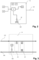
- Figure 3 shows a highly schematic diagram of an embodiment of the flow regulating device 10, illustrating the installation of the flow regulating device 10 in the fluid transportation system 400 between the thermal energy source 100 and the thermal energy transfer device 200.
- the valve V / damper D of the flow regulating device 10 is arranged on the return fluid transportation line 420 of the fluid transportation system 400.
- the temperature sensor device 22 comprises a first temperature sensor S1 configured to determine the supply temperature Ts of the fluid to the thermal energy source 100 and a second temperature sensor S2 configured to determine the return temperature Tr of the fluid from the thermal energy source 100.
- the flow regulating device 10 may be arranged within a single housing or distributed amongst various housings.
- the sensor devices flow rate sensor device 24, secondary flow rate sensor device 24', the temperature sensor device 22 and/or the secondary temperature sensor device 22'
- the sensor devices may be arranged in housings separate from the housing accommodating the processing unit 20, the communication module 26, the data store 27 and/or the interface to thermal energy transfer device 28.
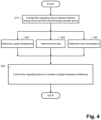
- FIG. 4 shows a flowchart illustrating steps of an embodiment of the method of operating an HVAC system 1 comprising a thermal energy source 100 and a thermal energy transfer device 200.
- a flow regulating device 10 is arranged between the thermal energy source 100 and the thermal energy transfer device 200 such as to be able to regulate a flow rate ⁇ of a fluid between the thermal energy source 100 and the thermal energy transfer device 200.
- the flow regulating device 10 regulates the flow rate ⁇ of the fluid using a valve V / damper D arranged in the supply fluid transportation line 410 and/or the return fluid transportation line 420 of the fluid transportation system 400 connecting the thermal energy source 100 and the thermal energy transfer device 200.
- steps S20, S30 and S40 supply temperature Ts; return temperature Tr respectively flow rate ⁇ of the fluid are determined (continuously, pseudo-continuously and/or at intervals during operation of the HVAC system).
- step S50 Based on the determined supply temperature Ts; return temperature Tr and flow rate ⁇ of the fluid, in step S50, the flow rate ( ⁇ ) of the fluid is controlled such as to maintain a target temperature difference dTt between the supply temperature Ts and the return temperature Tr.
- regulating the flow rate ( ⁇ ) of the fluid such as to maintain a target temperature difference dTt comprises:
- the flow rate ( ⁇ ) of the fluid is regulated such as to maintain a target temperature difference dTt while ensuring - in substep S52 that the return temperature Tr is above a minimum return temperature threshold Trmin and ensuring - in substep S54 - that the flow rate ⁇ is above an operational flow rate threshold ⁇ min of the thermal energy transfer device 200.
- Adherence to these two criteria addresses the aim to ensure that the HVAC system 1 operates optimally, with less interruptions and less prone to errors. Ensuring that the return temperature Tr is above a minimum return temperature threshold Trmin avoids the thermal energy transfer device 200 and/or the fluid transportation system 400 from being damaged due to freezing and/or condensation of the fluid.
- Ensuring that the flow rate ⁇ is above an operational flow rate threshold ⁇ min of the thermal energy transfer device 200 helps avoid unnecessary interruptions in the operation of the HVAC system 1 due to the thermal energy transfer device 200 being forced to shut down due to insufficient flow rate. Furthermore, ensuring that the flow rate ⁇ is above an operational flow rate threshold ⁇ min of the thermal energy transfer device 200 prevents unnecessary wear of the thermal energy transfer device 200 due to operation near or below its optimum parameters.
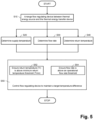
- the method further comprises - in a step S60 - increasing the flow rate ⁇ if the return temperature Tr is equal to or less than the sum of the minimum return temperature threshold Trmin and a temperature safety margin Tx. If, despite the flow regulating device 10 being fully open, the return temperature Tr is equal to or less than the sum of the minimum return temperature threshold Trmin and the temperature safety margin Tx, in a step S56, the flow regulating device 10 is closed off, preventing the flow of fluid to and/or from the thermal energy source 100. The flow regulating device 10 is closed off to avoid damage due to the return temperature Tr dropping below the minimum return temperature threshold Trmin. Furthermore, the flow regulating device 10 is closed off, if the flow rate ⁇ is equal to or less than the sum of the operational flow rate threshold ⁇ min and the flow safety margin ⁇ x despite the flow regulating device 10 being fully open.
- step S58 the flow regulating device 10 transmits a turn-off signal to the thermal energy transfer device 200 to avoid damage due to risk of the return temperature Tr dropping below the minimum return temperature threshold Trmin.
- step S60' the flow rate ⁇ is also increased if the flow rate ⁇ is equal to or less than the sum of the operational flow rate threshold ⁇ min and a flow safety margin ⁇ x.
- the flow regulating device 10 also transmits - in step S58 - a turn-off signal to the thermal energy transfer device 200 if the flow regulating device 10 is fully open and the flow rate ⁇ is equal to or less than the sum of the operational flow rate threshold ⁇ min and the flow safety margin ⁇ x.
- step S62 in order to allow the HVAC system 1 to be operated further as a function of a demand of thermal energy and hence to operate the HVAC system 1 even more efficiently, in step S62, the flow rate ⁇ is increased at predetermined time interval(s) dt in the presence of thermal energy demand. Hence, if the flow rate ⁇ has been previously reduced (e.g. to ensure a safe return temperature) or if the flow regulating device 10 has been previously closed off, the flow regulating device 10 makes successive attempts to meet the energy demand - while meeting the safe conditions of minimum return temperature threshold Trmin and operational flow rate threshold ⁇ min.
Landscapes
- Engineering & Computer Science (AREA)
- Chemical & Material Sciences (AREA)
- Combustion & Propulsion (AREA)
- Mechanical Engineering (AREA)
- General Engineering & Computer Science (AREA)
- Physics & Mathematics (AREA)
- Fluid Mechanics (AREA)
- Thermal Sciences (AREA)
- Fuzzy Systems (AREA)
- Mathematical Physics (AREA)
- Signal Processing (AREA)
- Air Conditioning Control Device (AREA)
Claims (20)
- Verfahren zum Betreiben einer HVAC-Anlage (1), umfassend eine Wärmeenergiequelle (100) und eine Wärmeenergieübertragungsvorrichtung (200), unter Verwendung einer Durchflussregelvorrichtung (10), dazu eingerichtet, eine Durchflussrate (Φ ) eines Fluids zwischen der Wärmeenergiequelle (100) und der Wärmeenergieübertragungsvorrichtung (200) zu regeln, das Verfahren umfassend:- Bestimmen einer Zufuhrtemperatur (Ts) des Fluids;- Bestimmen einer Rücklauftemperatur (Tr) des Fluids;- Bestimmen der Durchflussrate (Φ ) des Fluids; und- Regeln der Durchflussrate (Φ ) des Fluids derart, dass eine Soll-Temperaturdifferenz (dTt) zwischen der Zufuhrtemperatur (Ts) und der Rücklauftemperatur (Tr) aufrechterhalten wird, wobei sichergestellt wird, dass:- die Rücklauftemperatur (Tr) über einem minimalen Rücklauftemperaturschwellenwert (Trmin) liegt; und- die Durchflussrate (Φ ) über einem Betriebsdurchflussratenschwellenwert (Φ min) der Wärmeenergieübertragungsvorrichtung (200) liegt.
- Das Verfahren nach Anspruch 1 ferner umfassend die Erhöhung der Durchflussrate (Φ ), wenn die Rücklauftemperatur (Tr) gleich oder kleiner ist als die Summe aus dem minimalen Rücklauftemperaturschwellenwert (Trmin) und einer Temperatursicherheitsmarge (Tx).
- Das Verfahren nach Anspruch 2 ferner umfassend das Absperren der Durchflussregelvorrichtung (10) um den Fluss von Fluid zu und/oder von der Wärmeenergiequelle (100) zu verhindern:- wenn die Durchflussregelvorrichtung (10) vollständig geöffnet ist und die Rücklauftemperatur (Tr) gleich oder kleiner ist als die Summe aus dem minimalen Rücklauftemperaturschwellenwert (Trmin) und der Temperatursicherheitsmarge (Tx); und/oder- wenn die Durchflussregelvorrichtung (10) vollständig geöffnet ist und die Durchflussrate (Φ ) gleich oder kleiner ist als die Summe aus dem Betriebsdurchflussratenschwellenwert (Φ min) und der Durchflusssicherheitsmarge (Φ x); und/oder- bei Erkennung einer plötzlichen Änderung der Rücklauftemperatur (Tr), die auf eine Fehlfunktion/Deaktivierung der Wärmeenergieübertragungsvorrichtung (200) hinweist.
- Das Verfahren nach Anspruch 3 ferner umfassend das Übermitteln eines Abschaltsignals durch die Durchflussregelvorrichtung (10) an die Wärmeenergieübertragungsvorrichtung (200), wenn die Durchflussregelvorrichtung (10) vollständig geöffnet ist und die Rücklauftemperatur (Tr) gleich oder kleiner ist als die Summe aus dem minimalen Rücklauftemperaturschwellenwert (Trmin) und der Temperatursicherheitsmarge (Tx).
- Das Verfahren nach Anspruch 3 oder 4 ferner umfassend das Übermitteln eines Abschaltsignals durch die Durchflussregelvorrichtung (10) an die Wärmeenergieübertragungsvorrichtung (200), wenn die Durchflussregelvorrichtung (10) vollständig geöffnet ist und die Durchflussrate (Φ ) gleich oder kleiner ist als die Summe aus dem Betriebsdurchflussratenschwellenwert (Φ min) und der Durchflusssicherheitsmarge (Φ x).
- Das Verfahren nach einem der Ansprüche 1 bis 5 ferner umfassend die Erhöhung der Durchflussrate (Φ ), wenn die Durchflussrate (Φ ) gleich oder kleiner ist als die Summe aus dem Betriebsdurchflussratenschwellenwert (Φ min) und einer Durchflusssicherheitsmarge (Φ x).
- Das Verfahren nach einem der Ansprüche 1 bis 6, ferner umfassend:- Empfangen eines Signals, das einen Wärmeenergiebedarf der Wärmeenergieübertragungsvorrichtung (200) angibt, durch die Durchflussregelvorrichtung (10); und- Regulieren der Durchflussrate (Φ ) des Fluids in Abhängigkeit vom Wärmeenergiebedarf.
- Das Verfahren nach Anspruch 7 ferner umfassend die Erhöhung der Durchflussrate (Φ ) in einem oder mehreren vorbestimmten Zeitintervallen (dt) bei Vorhandensein von Wärmeenergiebedarf.
- Das Verfahren nach einem der Ansprüche 1 bis 8, wobei die Regelung der Durchflussrate (Φ ) des Fluids zu einem Aufrechterhalten einer Soll-Temperaturdifferenz (dTt) umfasst:- Aufrechterhalten einer Soll-Temperaturdifferenz (dTt) in Abhängigkeit von der Zufuhrtemperatur (Ts); oder- Maximieren der Temperaturdifferenz (dT); oder- Aufrechterhalten eines vordefinierten Rücklauftemperaturbereichs.
- Das Verfahren nach einem der Ansprüche 1 bis 9, ferner umfassend:- Empfangen von Daten durch die Durchflussregelvorrichtung (10), die eine sekundäre Zufuhrtemperatur (T2s) und/oder eine sekundäre Rücklauftemperatur (T2r) eines sekundären Fluids anzeigen, das zwischen der Wärmeenergieübertragungsvorrichtung (200) und einem Wärmeenergieverbraucher (300) fließt, und weiteres Regeln der Durchflussrate (Φ ) des Fluids in Abhängigkeit von der sekundären Zufuhrtemperatur (T2s) und/oder der sekundären Rücklauftemperatur (T2r); und/oder- Empfangen von Daten, die einen Energieverbrauch der Wärmeenergieübertragungsvorrichtung (200) anzeigen, durch die Durchflussregelvorrichtung (10) und weiteres Regulieren der Durchflussrate (Φ ) des Fluids als Funktion des Energieverbrauchs der Wärmeenergieübertragungsvorrichtung (200); und/oder- Empfangen von Daten, die den/die internen Zustand(e) der Wärmeenergieübertragungsvorrichtung (200) anzeigen, durch die Durchflussregelvorrichtung (10) und weiteres Regulieren der Durchflussrate (Φ ) des Fluids als Funktion des/der internen Zustands/Zustände der Wärmeenergieübertragungsvorrichtung (200).
- Durchflussregelvorrichtung (10) umfassend ein Ventil (V) und/oder eine Drossel (D), dazu ausgelegt, eine Durchflussrate (Φ ) eines Fluids zwischen einer Wärmeenergiequelle (100) und einer Wärmeenergieübertragungsvorrichtung (200) zu regeln, und eine Prozessoreinheit (20), dazu ausgelegt, das Verfahren nach einem der Ansprüche 1 bis 10 auszuführen.
- Die Durchflussregelvorrichtung (10) nach Anspruch 1 1, ferner umfassend:- eine Temperatursensorvorrichtung (22), dazu ausgelegt, eine Zufuhrtemperatur (Ts) des Fluids und eine Rücklauftemperatur (Tr) des Fluids zu bestimmen; und- eine Durchflusssensorvorrichtung (24), dazu ausgelegt, die Durchflussrate (Φ ) des Fluids zu und/oder von der Wärmeenergiequelle (100) und der Wärmeenergieübertragungsvorrichtung (200) zu bestimmen.
- Durchflussregelvorrichtung (10) nach Anspruch 12, wobei die Temperatursensorvorrichtung (22) einen ersten Temperatursensor (S1) umfasst, dazu ausgelegt, die Zufuhrtemperatur (Ts) des Fluids zu der Wärmeenergiequelle (100) zu bestimmen, und einen zweiten Temperatursensor (S2), dazu ausgelegt, die Rücklauftemperatur (Tr) des Fluids von der Wärmeenergiequelle (100) zu bestimmen.
- Die Durchflussregelvorrichtung (10) nach einem der Ansprüche 11 bis 13, ferner umfassend eine sekundäre Temperatursensorvorrichtung (22') oder mit dieser kommunikativ verbunden, die Temperatursensorvorrichtung (22') dazu ausgelegt, eine sekundäre Zufuhrtemperatur (Ts2) und/oder eine sekundäre Rücklauftemperatur(Tr2) eines sekundären Fluids in einem sekundären Fluidkreislauf des Wärmeenergieverbrauchers (300) zu bestimmen, wobei die Durchflussregelvorrichtung (10) ferner dazu ausgelegt ist, einen Wärmeenergiebedarf der Wärmeenergieübertragungsvorrichtung (200) auf der Grundlage der sekundären Zufuhrtemperatur (Ts2) und/oder der sekundären Rücklauftemperatur (Tr2) zu bestimmen.
- Durchflussregelvorrichtung (10) nach einem der Ansprüche 11 bis 14, ferner umfassend eine sekundäre Durchflussratensensorvorrichtung (24') oder mit dieser kommunikativ verbunden, die Durchflussratensensorvorrichtung (24') dazu ausgelegt, eine sekundäre Durchflussrate (Φ 2) eines sekundären Fluids in einem sekundären Fluidkreislauf des Wärmeenergieverbrauchers (300) zu bestimmen, wobei die Durchflussregelvorrichtung (10) ferner dazu ausgelegt ist, einen Wärmeenergiebedarf der Wärmeenergieübertragungsvorrichtung (200) basierend auf der sekundären Durchflussrate (Φ 2) zu bestimmen.
- Eine HVAC-Anlage (1), umfassend:- eine Wärmeenergiequelle (100)- eine Wärmeenergieübertragungsvorrichtung (200);- ein Fluidtransportsystem (400), umfassend:- eine Zufuhrfluidtransportleitung (410), eingerichtet zum Transport eines Fluids von der Wärmeenergiequelle (100) zur Wärmeenergieübertragungsvorrichtung (200);- eine Rücklauffluidtransportleitung (420) eingerichtet zum Transport des Fluids von der Wärmeenergieübertragungsvorrichtung (200) zur Wärmeenergiequelle (100);- eine Durchflussregelvorrichtung (10) nach einem der Ansprüche 11 bis 16, dazu eingerichtet, eine Durchflussrate (Φ ) des Fluids durch das Fluidtransportsystem (400) zwischen der Wärmeenergiequelle (100) und der Wärmeenergieübertragungsvorrichtung (200) zu regeln;wobei die HVAC-Anlage (1) dazu ausgelegt ist, das Verfahren nach einem der Ansprüche 1 bis 10 auszuführen.
- HVAC-Anlage (1) nach Anspruch 16, ferner umfassend einen Wärmeenergieverbraucher (300), der über ein sekundäres Fluidtransportsystem (500) mit der Wärmeenergieübertragungsvorrichtung (200) fluidisch verbunden ist, umfassend:- eine sekundäre Zufuhrfluidtransportleitung (510), eingerichtet zum Transport eines sekundären Fluids von der Wärmeenergieübertragungsvorrichtung (200) zum Wärmeenergieverbraucher (300); und- eine sekundäre Rücklauffluidtransportleitung (520), eingerichtet zum Transport des sekundären Fluids vom Wärmeenergieverbraucher (300) zur Wärmeenergieübertragungsvorrichtung (200).
- HVAC-Anlage (1) nach Anspruch 16 oder 17, wobei die Wärmeenergiequelle (100) dazu ausgelegt ist, der Wärmeenergieübertragungsvorrichtung (200) Wärme zuzuführen und/oder zu entziehen.
- HVAC-Anlage (1) nach Anspruch 18, wobei die Energieübertragungsvorrichtung (200) eine sekundäre Wärmeenergiequelle (210) umfasst, dazu ausgelegt, die von der Wärmeenergiequelle (100) bereitgestellte Wärmeenergie zu ergänzen.
- Computerprogrammprodukt umfassend Anweisungen, die bei Ausführung durch eine Prozessoreinheit (20) einer Durchflussregelvorrichtung (10) nach einem der Ansprüche 11 bis 15 die Durchflussregelvorrichtung (10) veranlassen, das Verfahren nach einem der Ansprüche 1 bis 10 auszuführen.
Applications Claiming Priority (2)
| Application Number | Priority Date | Filing Date | Title |
|---|---|---|---|
| CH0702192021 | 2021-08-30 | ||
| PCT/EP2022/073306 WO2023030943A1 (en) | 2021-08-30 | 2022-08-22 | A method of operating an hvac system |
Publications (2)
| Publication Number | Publication Date |
|---|---|
| EP4396500A1 EP4396500A1 (de) | 2024-07-10 |
| EP4396500B1 true EP4396500B1 (de) | 2025-06-11 |
Family
ID=83280257
Family Applications (1)
| Application Number | Title | Priority Date | Filing Date |
|---|---|---|---|
| EP22768691.2A Active EP4396500B1 (de) | 2021-08-30 | 2022-08-22 | Ein verfahren zum betrieb eines hvac-systems |
Country Status (3)
| Country | Link |
|---|---|
| US (1) | US20240353140A1 (de) |
| EP (1) | EP4396500B1 (de) |
| WO (1) | WO2023030943A1 (de) |
Family Cites Families (3)
| Publication number | Priority date | Publication date | Assignee | Title |
|---|---|---|---|---|
| US9631831B2 (en) * | 2010-11-17 | 2017-04-25 | Bilimo Holding Ag | Method for controlling the opening of an HVAC valve based on the energy-per-flow gradient |
| WO2019238631A1 (en) * | 2018-06-12 | 2019-12-19 | Belimo Holding Ag | Method and system for controlling energy transfer of a thermal energy exchanger |
| EP3891442B1 (de) * | 2018-12-05 | 2024-08-21 | Belimo Holding AG | Verfahren zur steuerung der öffnung eines ventils in einem hlk-system |
-
2022
- 2022-08-22 EP EP22768691.2A patent/EP4396500B1/de active Active
- 2022-08-22 US US18/683,947 patent/US20240353140A1/en active Pending
- 2022-08-22 WO PCT/EP2022/073306 patent/WO2023030943A1/en not_active Ceased
Also Published As
| Publication number | Publication date |
|---|---|
| EP4396500A1 (de) | 2024-07-10 |
| WO2023030943A1 (en) | 2023-03-09 |
| US20240353140A1 (en) | 2024-10-24 |
Similar Documents
| Publication | Publication Date | Title |
|---|---|---|
| US12235637B2 (en) | HVAC system with equipment failure warning | |
| US9641122B2 (en) | HVAC actuator with automatic end stop recalibration | |
| CN113883662B (zh) | 热能系统中的功率消耗的控制 | |
| JP2018534525A (ja) | ヒートポンピングの方法およびシステム | |
| CN112805528A (zh) | 传热系统的前馈流量控制 | |
| US11226135B2 (en) | Control apparatus and method for combination space and water heating | |
| WO2019129800A1 (en) | Smart thermostatic radiator or convector valve for a heating system and control method | |
| EP3431846B1 (de) | Adaptives ventilsteuerungssystem | |
| US10880213B2 (en) | Building management system network with power conservation via adaptive use of network protocols | |
| EP4396500B1 (de) | Ein verfahren zum betrieb eines hvac-systems | |
| US11725838B2 (en) | Environmental control system for reduced power consumption through utilization of wake-up radios | |
| EP3525060B1 (de) | Flusssteuerungsmodul und verfahren zur steuerung des flusses in einem hydronischen system | |
| EP4450881A1 (de) | Verfahren, flusssteuerungsvorrichtung und computerprogrammprodukt zum betrieb eines hlk-systems | |
| US11913657B2 (en) | Method and a computer system for monitoring and controlling an HVAC system | |
| JP2019158330A (ja) | 非接触の調整可能な設定を有するhvacアクチュエータ | |
| CN115066583A (zh) | 热能组件 | |
| EP3566101B1 (de) | Integrierter intelligenter ventilantrieb und ventilvorrichtung | |
| JP6654114B2 (ja) | 制御装置、制御方法及び制御システム | |
| EP3339753B1 (de) | System und verfahren zur durchsetzung eines manuell eingestellten temperatursollwerts in einem intelligenten wärmeverwaltungssystem | |
| US20100194590A1 (en) | Heating system | |
| EP3864486B1 (de) | Fernwärmesystem und verfahren zur steuerung des systems | |
| US20210180811A1 (en) | Self-learning wireless thermostat that minimizes battery drain | |
| TWI921808B (zh) | 用於供熱、通風或空調系統之冷凍器總成 | |
| US20200158360A1 (en) | Actuator enclosure assembly | |
| HK40087976A (zh) | 传热系统的前馈流量控制 |
Legal Events
| Date | Code | Title | Description |
|---|---|---|---|
| STAA | Information on the status of an ep patent application or granted ep patent |
Free format text: STATUS: UNKNOWN |
|
| STAA | Information on the status of an ep patent application or granted ep patent |
Free format text: STATUS: THE INTERNATIONAL PUBLICATION HAS BEEN MADE |
|
| PUAI | Public reference made under article 153(3) epc to a published international application that has entered the european phase |
Free format text: ORIGINAL CODE: 0009012 |
|
| STAA | Information on the status of an ep patent application or granted ep patent |
Free format text: STATUS: REQUEST FOR EXAMINATION WAS MADE |
|
| 17P | Request for examination filed |
Effective date: 20240308 |
|
| AK | Designated contracting states |
Kind code of ref document: A1 Designated state(s): AL AT BE BG CH CY CZ DE DK EE ES FI FR GB GR HR HU IE IS IT LI LT LU LV MC MK MT NL NO PL PT RO RS SE SI SK SM TR |
|
| DAV | Request for validation of the european patent (deleted) | ||
| DAX | Request for extension of the european patent (deleted) | ||
| GRAP | Despatch of communication of intention to grant a patent |
Free format text: ORIGINAL CODE: EPIDOSNIGR1 |
|
| STAA | Information on the status of an ep patent application or granted ep patent |
Free format text: STATUS: GRANT OF PATENT IS INTENDED |
|
| INTG | Intention to grant announced |
Effective date: 20250307 |
|
| GRAS | Grant fee paid |
Free format text: ORIGINAL CODE: EPIDOSNIGR3 |
|
| GRAA | (expected) grant |
Free format text: ORIGINAL CODE: 0009210 |
|
| STAA | Information on the status of an ep patent application or granted ep patent |
Free format text: STATUS: THE PATENT HAS BEEN GRANTED |
|
| AK | Designated contracting states |
Kind code of ref document: B1 Designated state(s): AL AT BE BG CH CY CZ DE DK EE ES FI FR GB GR HR HU IE IS IT LI LT LU LV MC MK MT NL NO PL PT RO RS SE SI SK SM TR |
|
| REG | Reference to a national code |
Ref country code: GB Ref legal event code: FG4D |
|
| REG | Reference to a national code |
Ref country code: CH Ref legal event code: EP |
|
| REG | Reference to a national code |
Ref country code: DE Ref legal event code: R096 Ref document number: 602022015882 Country of ref document: DE |
|
| REG | Reference to a national code |
Ref country code: IE Ref legal event code: FG4D |
|
| P01 | Opt-out of the competence of the unified patent court (upc) registered |
Free format text: CASE NUMBER: APP_30832/2025 Effective date: 20250626 |
|
| PG25 | Lapsed in a contracting state [announced via postgrant information from national office to epo] |
Ref country code: FI Free format text: LAPSE BECAUSE OF FAILURE TO SUBMIT A TRANSLATION OF THE DESCRIPTION OR TO PAY THE FEE WITHIN THE PRESCRIBED TIME-LIMIT Effective date: 20250611 Ref country code: ES Free format text: LAPSE BECAUSE OF FAILURE TO SUBMIT A TRANSLATION OF THE DESCRIPTION OR TO PAY THE FEE WITHIN THE PRESCRIBED TIME-LIMIT Effective date: 20250611 |
|
| PGFP | Annual fee paid to national office [announced via postgrant information from national office to epo] |
Ref country code: DE Payment date: 20250819 Year of fee payment: 4 |
|
| REG | Reference to a national code |
Ref country code: LT Ref legal event code: MG9D |
|
| PG25 | Lapsed in a contracting state [announced via postgrant information from national office to epo] |
Ref country code: GR Free format text: LAPSE BECAUSE OF FAILURE TO SUBMIT A TRANSLATION OF THE DESCRIPTION OR TO PAY THE FEE WITHIN THE PRESCRIBED TIME-LIMIT Effective date: 20250912 Ref country code: NO Free format text: LAPSE BECAUSE OF FAILURE TO SUBMIT A TRANSLATION OF THE DESCRIPTION OR TO PAY THE FEE WITHIN THE PRESCRIBED TIME-LIMIT Effective date: 20250911 |
|
| REG | Reference to a national code |
Ref country code: NL Ref legal event code: MP Effective date: 20250611 |
|
| PG25 | Lapsed in a contracting state [announced via postgrant information from national office to epo] |
Ref country code: BG Free format text: LAPSE BECAUSE OF FAILURE TO SUBMIT A TRANSLATION OF THE DESCRIPTION OR TO PAY THE FEE WITHIN THE PRESCRIBED TIME-LIMIT Effective date: 20250611 |
|
| PG25 | Lapsed in a contracting state [announced via postgrant information from national office to epo] |
Ref country code: HR Free format text: LAPSE BECAUSE OF FAILURE TO SUBMIT A TRANSLATION OF THE DESCRIPTION OR TO PAY THE FEE WITHIN THE PRESCRIBED TIME-LIMIT Effective date: 20250611 |
|
| PGFP | Annual fee paid to national office [announced via postgrant information from national office to epo] |
Ref country code: AT Payment date: 20251020 Year of fee payment: 4 |
|
| PGFP | Annual fee paid to national office [announced via postgrant information from national office to epo] |
Ref country code: CH Payment date: 20250903 Year of fee payment: 4 |
|
| PG25 | Lapsed in a contracting state [announced via postgrant information from national office to epo] |
Ref country code: RS Free format text: LAPSE BECAUSE OF FAILURE TO SUBMIT A TRANSLATION OF THE DESCRIPTION OR TO PAY THE FEE WITHIN THE PRESCRIBED TIME-LIMIT Effective date: 20250911 |
|
| PG25 | Lapsed in a contracting state [announced via postgrant information from national office to epo] |
Ref country code: LV Free format text: LAPSE BECAUSE OF FAILURE TO SUBMIT A TRANSLATION OF THE DESCRIPTION OR TO PAY THE FEE WITHIN THE PRESCRIBED TIME-LIMIT Effective date: 20250611 |
|
| PG25 | Lapsed in a contracting state [announced via postgrant information from national office to epo] |
Ref country code: NL Free format text: LAPSE BECAUSE OF FAILURE TO SUBMIT A TRANSLATION OF THE DESCRIPTION OR TO PAY THE FEE WITHIN THE PRESCRIBED TIME-LIMIT Effective date: 20250611 |
|
| PG25 | Lapsed in a contracting state [announced via postgrant information from national office to epo] |
Ref country code: PT Free format text: LAPSE BECAUSE OF FAILURE TO SUBMIT A TRANSLATION OF THE DESCRIPTION OR TO PAY THE FEE WITHIN THE PRESCRIBED TIME-LIMIT Effective date: 20251013 |
|
| REG | Reference to a national code |
Ref country code: AT Ref legal event code: MK05 Ref document number: 1802540 Country of ref document: AT Kind code of ref document: T Effective date: 20250611 |
|
| PG25 | Lapsed in a contracting state [announced via postgrant information from national office to epo] |
Ref country code: IS Free format text: LAPSE BECAUSE OF FAILURE TO SUBMIT A TRANSLATION OF THE DESCRIPTION OR TO PAY THE FEE WITHIN THE PRESCRIBED TIME-LIMIT Effective date: 20251011 |
|
| PG25 | Lapsed in a contracting state [announced via postgrant information from national office to epo] |
Ref country code: AT Free format text: LAPSE BECAUSE OF FAILURE TO SUBMIT A TRANSLATION OF THE DESCRIPTION OR TO PAY THE FEE WITHIN THE PRESCRIBED TIME-LIMIT Effective date: 20250611 Ref country code: SM Free format text: LAPSE BECAUSE OF FAILURE TO SUBMIT A TRANSLATION OF THE DESCRIPTION OR TO PAY THE FEE WITHIN THE PRESCRIBED TIME-LIMIT Effective date: 20250611 |
|
| PG25 | Lapsed in a contracting state [announced via postgrant information from national office to epo] |
Ref country code: CZ Free format text: LAPSE BECAUSE OF FAILURE TO SUBMIT A TRANSLATION OF THE DESCRIPTION OR TO PAY THE FEE WITHIN THE PRESCRIBED TIME-LIMIT Effective date: 20250611 |
|
| PG25 | Lapsed in a contracting state [announced via postgrant information from national office to epo] |
Ref country code: PL Free format text: LAPSE BECAUSE OF FAILURE TO SUBMIT A TRANSLATION OF THE DESCRIPTION OR TO PAY THE FEE WITHIN THE PRESCRIBED TIME-LIMIT Effective date: 20250611 |
|
| PG25 | Lapsed in a contracting state [announced via postgrant information from national office to epo] |
Ref country code: EE Free format text: LAPSE BECAUSE OF FAILURE TO SUBMIT A TRANSLATION OF THE DESCRIPTION OR TO PAY THE FEE WITHIN THE PRESCRIBED TIME-LIMIT Effective date: 20250611 |
|
| PG25 | Lapsed in a contracting state [announced via postgrant information from national office to epo] |
Ref country code: SK Free format text: LAPSE BECAUSE OF FAILURE TO SUBMIT A TRANSLATION OF THE DESCRIPTION OR TO PAY THE FEE WITHIN THE PRESCRIBED TIME-LIMIT Effective date: 20250611 |
|
| PG25 | Lapsed in a contracting state [announced via postgrant information from national office to epo] |
Ref country code: RO Free format text: LAPSE BECAUSE OF FAILURE TO SUBMIT A TRANSLATION OF THE DESCRIPTION OR TO PAY THE FEE WITHIN THE PRESCRIBED TIME-LIMIT Effective date: 20250611 |
|
| PG25 | Lapsed in a contracting state [announced via postgrant information from national office to epo] |
Ref country code: MC Free format text: LAPSE BECAUSE OF FAILURE TO SUBMIT A TRANSLATION OF THE DESCRIPTION OR TO PAY THE FEE WITHIN THE PRESCRIBED TIME-LIMIT Effective date: 20250611 |
|
| PG25 | Lapsed in a contracting state [announced via postgrant information from national office to epo] |
Ref country code: DK Free format text: LAPSE BECAUSE OF FAILURE TO SUBMIT A TRANSLATION OF THE DESCRIPTION OR TO PAY THE FEE WITHIN THE PRESCRIBED TIME-LIMIT Effective date: 20250611 |
|
| PG25 | Lapsed in a contracting state [announced via postgrant information from national office to epo] |
Ref country code: LU Free format text: LAPSE BECAUSE OF NON-PAYMENT OF DUE FEES Effective date: 20250822 Ref country code: IT Free format text: LAPSE BECAUSE OF FAILURE TO SUBMIT A TRANSLATION OF THE DESCRIPTION OR TO PAY THE FEE WITHIN THE PRESCRIBED TIME-LIMIT Effective date: 20250611 |
|
| PLBE | No opposition filed within time limit |
Free format text: ORIGINAL CODE: 0009261 |
|
| STAA | Information on the status of an ep patent application or granted ep patent |
Free format text: STATUS: NO OPPOSITION FILED WITHIN TIME LIMIT |
|
| REG | Reference to a national code |
Ref country code: CH Ref legal event code: L10 Free format text: ST27 STATUS EVENT CODE: U-0-0-L10-L00 (AS PROVIDED BY THE NATIONAL OFFICE) Effective date: 20260423 |