EP3339753B1 - System und verfahren zur durchsetzung eines manuell eingestellten temperatursollwerts in einem intelligenten wärmeverwaltungssystem - Google Patents
System und verfahren zur durchsetzung eines manuell eingestellten temperatursollwerts in einem intelligenten wärmeverwaltungssystem Download PDFInfo
- Publication number
- EP3339753B1 EP3339753B1 EP16306794.5A EP16306794A EP3339753B1 EP 3339753 B1 EP3339753 B1 EP 3339753B1 EP 16306794 A EP16306794 A EP 16306794A EP 3339753 B1 EP3339753 B1 EP 3339753B1
- Authority
- EP
- European Patent Office
- Prior art keywords
- thermostat
- temperature setpoint
- room
- trv
- heat
- Prior art date
- Legal status (The legal status is an assumption and is not a legal conclusion. Google has not performed a legal analysis and makes no representation as to the accuracy of the status listed.)
- Active
Links
Images

Classifications
-
- F—MECHANICAL ENGINEERING; LIGHTING; HEATING; WEAPONS; BLASTING
- F24—HEATING; RANGES; VENTILATING
- F24D—DOMESTIC- OR SPACE-HEATING SYSTEMS, e.g. CENTRAL HEATING SYSTEMS; DOMESTIC HOT-WATER SUPPLY SYSTEMS; ELEMENTS OR COMPONENTS THEREFOR
- F24D19/00—Details
- F24D19/10—Arrangement or mounting of control or safety devices
- F24D19/1006—Arrangement or mounting of control or safety devices for water heating systems
- F24D19/1009—Arrangement or mounting of control or safety devices for water heating systems for central heating
- F24D19/1015—Arrangement or mounting of control or safety devices for water heating systems for central heating using a valve or valves
-
- F—MECHANICAL ENGINEERING; LIGHTING; HEATING; WEAPONS; BLASTING
- F24—HEATING; RANGES; VENTILATING
- F24D—DOMESTIC- OR SPACE-HEATING SYSTEMS, e.g. CENTRAL HEATING SYSTEMS; DOMESTIC HOT-WATER SUPPLY SYSTEMS; ELEMENTS OR COMPONENTS THEREFOR
- F24D19/00—Details
- F24D19/10—Arrangement or mounting of control or safety devices
- F24D19/1006—Arrangement or mounting of control or safety devices for water heating systems
- F24D19/1009—Arrangement or mounting of control or safety devices for water heating systems for central heating
- F24D19/1015—Arrangement or mounting of control or safety devices for water heating systems for central heating using a valve or valves
- F24D19/1018—Radiator valves
-
- F—MECHANICAL ENGINEERING; LIGHTING; HEATING; WEAPONS; BLASTING
- F24—HEATING; RANGES; VENTILATING
- F24D—DOMESTIC- OR SPACE-HEATING SYSTEMS, e.g. CENTRAL HEATING SYSTEMS; DOMESTIC HOT-WATER SUPPLY SYSTEMS; ELEMENTS OR COMPONENTS THEREFOR
- F24D3/00—Hot-water central heating systems
- F24D3/02—Hot-water central heating systems with forced circulation, e.g. by pumps
-
- G—PHYSICS
- G05—CONTROLLING; REGULATING
- G05D—SYSTEMS FOR CONTROLLING OR REGULATING NON-ELECTRIC VARIABLES
- G05D23/00—Control of temperature
- G05D23/19—Control of temperature characterised by the use of electric means
- G05D23/1902—Control of temperature characterised by the use of electric means characterised by the use of a variable reference value
- G05D23/1905—Control of temperature characterised by the use of electric means characterised by the use of a variable reference value associated with tele control
-
- G—PHYSICS
- G05—CONTROLLING; REGULATING
- G05D—SYSTEMS FOR CONTROLLING OR REGULATING NON-ELECTRIC VARIABLES
- G05D23/00—Control of temperature
- G05D23/19—Control of temperature characterised by the use of electric means
- G05D23/1927—Control of temperature characterised by the use of electric means using a plurality of sensors
- G05D23/193—Control of temperature characterised by the use of electric means using a plurality of sensors sensing the temperaure in different places in thermal relationship with one or more spaces
- G05D23/1932—Control of temperature characterised by the use of electric means using a plurality of sensors sensing the temperaure in different places in thermal relationship with one or more spaces to control the temperature of a plurality of spaces
- G05D23/1934—Control of temperature characterised by the use of electric means using a plurality of sensors sensing the temperaure in different places in thermal relationship with one or more spaces to control the temperature of a plurality of spaces each space being provided with one sensor acting on one or more control means
-
- F—MECHANICAL ENGINEERING; LIGHTING; HEATING; WEAPONS; BLASTING
- F24—HEATING; RANGES; VENTILATING
- F24D—DOMESTIC- OR SPACE-HEATING SYSTEMS, e.g. CENTRAL HEATING SYSTEMS; DOMESTIC HOT-WATER SUPPLY SYSTEMS; ELEMENTS OR COMPONENTS THEREFOR
- F24D2220/00—Components of central heating installations excluding heat sources
- F24D2220/02—Fluid distribution means
- F24D2220/0257—Thermostatic valves
-
- F—MECHANICAL ENGINEERING; LIGHTING; HEATING; WEAPONS; BLASTING
- F24—HEATING; RANGES; VENTILATING
- F24D—DOMESTIC- OR SPACE-HEATING SYSTEMS, e.g. CENTRAL HEATING SYSTEMS; DOMESTIC HOT-WATER SUPPLY SYSTEMS; ELEMENTS OR COMPONENTS THEREFOR
- F24D2220/00—Components of central heating installations excluding heat sources
- F24D2220/04—Sensors
- F24D2220/042—Temperature sensors
-
- Y—GENERAL TAGGING OF NEW TECHNOLOGICAL DEVELOPMENTS; GENERAL TAGGING OF CROSS-SECTIONAL TECHNOLOGIES SPANNING OVER SEVERAL SECTIONS OF THE IPC; TECHNICAL SUBJECTS COVERED BY FORMER USPC CROSS-REFERENCE ART COLLECTIONS [XRACs] AND DIGESTS
- Y02—TECHNOLOGIES OR APPLICATIONS FOR MITIGATION OR ADAPTATION AGAINST CLIMATE CHANGE
- Y02B—CLIMATE CHANGE MITIGATION TECHNOLOGIES RELATED TO BUILDINGS, e.g. HOUSING, HOUSE APPLIANCES OR RELATED END-USER APPLICATIONS
- Y02B30/00—Energy efficient heating, ventilation or air conditioning [HVAC]
- Y02B30/70—Efficient control or regulation technologies, e.g. for control of refrigerant flow, motor or heating
Definitions
- the invention relates to the field of smart thermal management of household consumer devices and, in particular, the thermal control within a house.
- the invention concerns a system and method for enforcing a manual temperature setpoint within an intelligent thermal management system.
- Each heat emitter is equipped with a valve that regulates the heat flux inside the heat emitter.
- the valve is either a mechanical valve or a thermostatic valve.
- the user adjusts the position of the valve depending on the ambient heat he/she wishes inside the room. If the room comprises a plurality of heat emitters, the user has to adjust the position of each valve, preferably in a compliant way. This often leads to incorrect settings, leading to unapropriate behaviours and additional energy costs.
- thermostatic valve also called thermostatic radiator valve or TRV
- TRV thermostatic radiator valve
- a thermostatic valve allows a better thermal management within a room without a need of manually adapting the position of the valve. It is also possible to program various time slots, each corresponding to a temperature setpoint in the room. For example, the temperature setpoint of each valve may be set at 20°C from 7 am to 11 pm and at 18°C during the night, so as to save energy.
- a thermostat can be used to control operation of a central heating system, for example a boiler or more generally a heat generator, and regulate the temperature of one or more rooms by setting a temperature setpoint and monitoring the temperature within the home. If the room temperature falls below the temperature setpoint, the thermostat sends an appropriate signal to operate heating schedule as deemed necessary.
- thermostatic valves Today, it is well known to use, in combination with thermostatic valves, a variety of communication mediums to enable the thermal control within a room or a house, for example power lines, cabled or wireless networks.
- the user may perform this thermal control with a connection via the Internet, allowing a further degree of remote control.
- a connection may be realized thanks to a relay that can be driven by the user via a dedicated application or a web application from a PC or another user terminal (i.e. tablet or smart phone) connected to the Internet.
- EP2584273A1 relates to a temperature controlling solution.
- the temperature controlling system comprises an unit for supplying energy to temperatured zones and a central control unit for controlling at least the unit for supplying energy in relation to an amount of energy required in the zones.
- the zones are selected whose amount of energy is considered by the control unit. This reduces the energy consumption of the unit for supplying energy.
- GB2501765 discloses an apparatus to control a central heating system and that comprises a relay coupled to the system, a thermostat in wireless communication with the relay, and a server located remotely from the system, i.e. in a separate building.
- the thermostat determines an ambient temperature and communicates the temperature to the relay.
- the server receives the temperature from the relay and generates one or more instructions based upon the ambient temperature, which are sent to the relay to control operation of the system.
- the one or more instructions can start/stop a boiler of the system and set desired temperature thresholds of one or more thermostatic radiator valves of respective radiators.
- the relay may communicate with the server over the internet using a local WiFi router.
- a user may use a web portal to enter desired objectives of the system on the server, such as desired start times and target temperatures.
- the server may use other user information, such as GPS tracking of the user or third-party application programming interfaces, to control the system. If communication between the relay and the server fails, the thermostat can resume control of the system.
- a solution to overcome this inconvenient is to allow an input of a temperature setting at the thermostatic radiator valve to bypass a lower temperature setting at the thermostat.
- the invention provides a system and method for enforcing a manual temperature setpoint within a smart thermal management system, thus enabling a better thermal comfort within a room without affecting the performance of the thermal control throughout the building.
- the subject of the invention is a thermostatic radiator valve (TRV) configured to adjust a flow of heating fluid from a heat generator entering a heat emitter in a room having a room temperature based on a temperature setpoint, the heat generator and the heat emitter being configured to heat a building, the TRV comprising communication link to a thermostat controlling the heat generator based on a thermostat temperature setpoint and an input interface configured to allow a user to enter a defined temperature setpoint or acquire the defined temperature setpoint; wherein the TRV is configured to send to the thermostat a command to trigger the heat generator if the defined temperature setpoint is higher than the room temperature and the thermostat has reached the thermostat temperature setpoint.
- TRV thermostatic radiator valve
- Such a TRV is able to directly trigger the heat generator when a temperature higher than the thermostat temperature setpoint is required in a room. From this, it follows that a user can perform a manual change in the temperature setpoint of a room, thus leading to the triggering of the heat generator previously shut down because of the achievement of the thermostat temperature setpoint.
- the invention relates to a thermostatic radiator valve TRV configured to adjust a flow of heat transfer fluid from a thermal energy generator entering a heat exchanger based on a temperature setpoint, the thermal energy generator and the heat exchanger configured to heat or cool a room with a room temperature, the TRV comprising a communication link to a thermostat controlling the thermal energy generator based on a thermostat temperature setpoint; an input interface configured to allow a user to enter a defined temperature setpoint or acquire the defined temperature setpoint; wherein the TRV is configured to send to the thermostat a command to trigger the thermal energy generator if a difference between the defined temperature setpoint and the room temperature has a same sign as a gradient of temperature to be generated by the thermal energy generator and the thermostat has reached the thermostat temperature setpoint.
- the communication link includes a relay configured to connect to the thermostat, and the TRV is configured to send to the relay the command for the thermostat to trigger the heat generator.
- the relay can concentrate the data of all TRVs within the house and it may be an access point to have an access to these data. Therefore a user can directly connect to the relay to access to these data.
- the relay is connected to an internet network to enable the reception of external commands.
- the invention also concerns a method for enforcing a manual temperature setpoint using a thermostatic radiator valve (TRV) configured to adjust a flow of heating fluid from a heat generator entering a heat emitter in a room with a room temperature based on a temperature setpoint, the heat generator and the heat emitter being configured to heat a building, the TRV comprising a communication link to a thermostat controlling the heat generator based on a thermostat temperature setpoint; an input interface configured to allow a user to enter a defined temperature setpoint or acquire the defined temperature setpoint; the method comprising the step of sending an order to the thermostat to trigger the heat generator, if the defined temperature setpoint is higher than the room temperature and the thermostat has reached the thermostat temperature setpoint.
- This method enables to directly trigger the heat generator when a temperature higher than the thermostat temperature setpoint is required in a room.
- the invention also concerns a thermostatic radiator valve (TRV) configured to adjust a flow of cooling fluid from a cooling generator entering a cooling emitter in a room having a room temperature based on a temperature setpoint, the cooling generator and the cooling emitter being configured to cool a building, the TRV comprising communication link to a thermostat controlling the cooling generator based on a thermostat temperature setpoint and an input interface configured to allow a user to enter a defined temperature setpoint or acquire the defined temperature setpoint; wherein the TRV is configured to send to the thermostat a command to trigger the heat generator if a difference between the defined temperature setpoint and the room temperature has a same sign as a gradient of temperature to be generated by the thermal energy generator and the thermostat has reached the thermostat temperature setpoint.
- TRV thermostatic radiator valve
- the invention is described with self-regulating valve fitted to hot water heating system radiator and heat generator like a boiler, but the invention can be applied by analogy to any heat generator (from thermal, geothermal energy) and corresponding valves.
- thermostatic radiator valve 21 in the field of heating but relates more generally to a thermostatic radiator valve TRV configured to adjust a flow of heat transfer fluid from a thermal energy generator entering a heat exchanger based on a temperature setpoint, the thermal energy generator and the heat exchanger configured to heat or cool a room with a room temperature, the TRV comprising a communication link to a thermostat controlling the thermal energy generator based on a thermostat temperature setpoint; an input interface configured to allow a user to enter a defined temperature setpoint or acquire the defined temperature setpoint; wherein the TRV is configured to send to the thermostat a command to trigger the thermal energy generator if a difference between the defined temperature setpoint and the room temperature has a same sign as a gradient of temperature to be generated by the thermal energy generator and the thermostat has reached the thermostat temperature setpoint.
- TRV configured to adjust a flow of heat transfer fluid from a thermal energy generator entering a heat exchanger based on a temperature setpoint, the thermal energy generator and the heat exchanger configured to heat or cool a room with a room temperature
- the heat transfer fluid being a heating fluid
- the heat exchanger being a heat emitter
- the thermal energy generator being a heat generator
- the heat transfer fluid can also be a cooling fluid
- the heat exchanger a cooling emitter
- the thermal energy generator a cooling generator
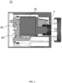
- FIG. 1 schematically represents a thermostatic radiator valve 21 according to the invention.
- the thermostatic valve 21 comprises a motor 81, an electronic board 82.
- the thermostatic radiator valve 21 may comprise a temperature sensor 83.
- the motor 81 may be replaced by any other system able to reduce the fluid flow in the heat emitter.
- the thermostatic radiator valve (TRV) 21 is a self-regulating valve fitted to a heating fluid from a heat generator entering a heat emitter (or radiator) to which the TRV 21 is connected.
- the TRV 21 may include a memory to store some data such as a temperature setpoint.
- an electronic board 82 comprising a calculator may activate the motor 81 to mechanically adapt the aperture 5 of the TRV 21.
- Such a TRV 21 gradually closes as the temperature of the surrounding area increases, limiting the amount of heating fluid entering the heat emitter.
- FIG. 2 schematically represents an embodiment of the thermostatic radiator valve 21 for enforcing a manual temperature setpoint according to the invention.
- a heat generator 10 and a heat emitter 11 are configured to heat a building 9.
- the TRV 21, stored in a room 101 with a room temperature Tr1 is configured to adjust the flow of heating fluid from the heat generator 10 entering the heat emitter 11 based on a temperature setpoint.
- the TRV 21 comprises a communication link 41 to a thermostat 60 controlling the heat generator 10 based on a thermostat temperature setpoint 61.
- the communication link 41 may be performed through a wired or radio connection 14 such as Zigbee, Wi-Fi, Bluetooth TM ....
- the TRV 21 comprises an input interface configured to allow a user to enter a defined temperature setpoint or acquire the defined temperature setpoint T2 from a user terminal connected to the connection 14 to which the TRV and the thermostat are connected.
- the TRV is configured to send to the thermostat 60 a command to trigger the heat generator 10, if a difference between the defined temperature setpoint T2 and the room temperature Tr1 has a same sign as a gradient of temperature to be generated by the thermal energy generator and the thermostat 60 has reached the thermostat temperature setpoint 61.
- the gradient of temperature indicates the evolution of the temperature. It is positive in case of a temperature increase.
- a positive temperature gradient means that the thermal energy generator should operate so as to increase the temperature (i.e the thermal energy generator generates a positive temperature gradient).
- a negative temperature gradient means that the thermal energy generator should operate so as to decrease the temperature (i.e the thermal energy generator generates a negative temperature gradient).
- the TRV sends to the thermostat 60 the command to trigger the heat generator 10 if the defined temperature setpoint T2 is higher than the room temperature Tr1 (i.e. the difference between T2 and Tr1 is positive) and the thermostat 60 has reached the thermostat temperature setpoint 61.
- the TRV sends to the thermostat 60 the command to trigger the cooling generator if the defined temperature setpoint T2 is lower than the room temperature Tr1 (i.e. the difference between T2 and Tr1 is negative) and the thermostat 60 has reached the thermostat temperature setpoint 61.
- the thermostat 60 is located in a third room 103, that is to say a room where there are no TRV, to better illustrate the enforcing of the manual temperature setpoint, also called the activation of the manual boost.
- the invention works also in a case with a thermostat placed in the same room where there is a TRV.
- TRV The advantage of such a TRV is to allow a user to heat up a room by enabling the TRV in this room to trigger the heat generator 10 directly, even if the thermostat temperature setpoint is achieved. Indeed, in such a case, having achieved its thermostat temperature setpoint (i.e. Tr1 is higher than 61), the thermostat normally orders the heat generator 10 to shut down because no further heating in this room is needed. Thanks to the TRV of the invention, a user is able to impose via the input interface of the TRV a new defined temperature setpoint T2 to the TRV in this room.
- the TRV sends a command to the thermostat 60 to trigger the heat generator 10 previously shut down, and this even if the thermostat temperature setpoint 61 is achieved in this room.
- the TRV 21 is able to trigger the heat generator 10 if the new defined temperature setpoint T2 input to the TRV 21 requires a heating up of the room, that is to say if the defined temperature setpoint T2 is higher than the room temperature Tr1 and the thermostat 60 has reached the thermostat temperature setpoint 61.
- the thermostat 60 has reached its temperature setpoint when it is no more regulating (i. e. TR1 is much higher than 61).
- TR1 is much higher than 61.
- the defined temperature setpoint can be lower than the thermostat temperature setpoint 61 and activate the manual boost if the thermostat was no more regulating.
- the TRV 23 in the same room as the TRV 21 and to the TRV 22 in another room It is of particular interest when a user inputs a new defined temperature setpoint T2 at the TRV 22 in the room 102.
- the room temperature Tr1 of the room 101 is equal to the thermostat temperature 61. Therefore there is no need to heat up the room further and the heat generator 10 is shut down.
- the condition is fulfilled for the TRV 22 to send to the thermostat 60 a command to trigger the heat generator 10 when the defined temperature setpoint T2 to the TRV 23 is higher than the room temperature Tr2 and the thermostat 60 has reached the thermostat temperature setpoint 61.
- the TRV according to the invention enables to enforce a manual temperature setpoint T2 within a house 9 comprising at least a first, a second and a third room 101, 102, 103, each room having a real temperature Tr1, Tr2, Tr3 and a thermostat temperature setpoint 61.
- the thermostat 60 is for example located in the third room 103 and configured to communicate a heat generator parameter to the heat generator 10 to control the heat generator 10 for sending a flow of heating fluid to heat up each room or turning the heat generator off according to the real temperature Tr3 and the thermostat temperature setpoint 61 of the third room 103.
- one of the plurality of TRVs 22 in the second room 102 is configured to send to the thermostat 60 thanks to its communication link 42 via the dedicated network 14 a heat generator parameter intended to trigger the turned off heat generator 10 when a manual temperature setpoint T2 imposed to one of the plurality of heat emitters 12 of the second room 102 is higher than the room temperature Tr2 and the thermostat 60 has reached the thermostat temperature setpoint 61.
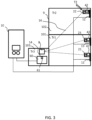
- FIG. 3 schematically represents another embodiment of the thermostatic radiator valve for enforcing a manual temperature setpoint according to the invention.
- the communication link 41, 42, 43 of the TRV 21, 22, 23 includes a relay 8 configured to connect to the thermostat 60, and the TRV is configured to send to the relay 8 the command for the thermostat 60 to trigger the heat generator 10.
- the relay 8 may be connected to the TRVs through a wired or radio connection 14 such as Zigbee, Wi-Fi, Bluetooth... Also the relay 8 may be connected to the thermostat 60 through the same or another wired or wireless connection.
- the relay 8 is connected to an internet network that enables the reception of commands external to the system.
- the relay 8 enables to concentrate the data from the TRVs.
- a TRV according to the invention may comprise a memory to store its own data like for example its temperature setpoint, the new defined temperature setpoint T2, but also data from the one or more other TRVs.
- the relay 8 can concentrate the data of all the TRVs. This feature presents the advantage of the possibility for a user to connect, for example, his smartphone to the relay 8 via a wired or wireless connection (Bluetooth, Wi-Fi, ...) and check data of all TRVs at one sight. This may help the user to take a decision to input a new defined temperature setpoint T2.
- the relay is coupled to the internet network
- a user can sit in the room 101 and be under the impression that he is cold. Without moving, he/she can check the temperature setpoint of each TRV of the house by connecting his smartphone to the relay 8. He may notice on his smartphone that the temperature setpoint of the TRVs 21, 23 in the room 101 is 20°C, the thermostat temperature setpoint is 20°C and the temperature setpoint of the TRV 22 in the room 102 is 21 °C. Therefore, the heat generator 10 is off since the thermostat temperature setpoint of 20 °C is achieved.
- the user may want to input a new defined temperature setpoint T2 at 22°C to the TRV 23 in the room 101 where he is. Since the new defined temperature setpoint T2 (22°C) is higher than the room temperature Tr1 and the thermostat temperature setpoint (20°C), and even if the room temperature is already at 20°C, the TRV 23 sends to the thermostat 60 the command to trigger the heat generator 10 to achieve the new defined temperature setpoint of 22°C in the room 101. The command sent to the thermostat 60 by the TRV 23 may transit through the relay connected to the thermostat 60.
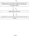
- FIG. 4 represents a block diagram of the steps of a method for enforcing a manual temperature setpoint according to the invention.
- the method for enforcing a manual temperature setpoint uses a thermostatic radiator valve (TRV) 21, as described before, configured to adjust a flow of heating fluid from a heat generator 10 entering a heat emitter 11 in a room 101 with a room temperature Tr1 based on a temperature setpoint, the heat generator 10 and the heat emitter 11 configured to heat a building 9, the TRV 21 comprising a communication link 41 to a thermostat 60 controlling the heat generator 10 based on a thermostat temperature setpoint 61, an input interface configured to allow a user to enter a defined temperature setpoint T2 or acquire the defined temperature setpoint.
- TRV thermostatic radiator valve
- the method comprises the step 501 of sending an order to the thermostat 60 to trigger the heat generator 10 if the defined temperature setpoint T2 is higher than the room temperature Tr1 (or more generally if a difference between the defined temperature setpoint T2 and the room temperature Tr1 has a same sign as a gradient of temperature to be generated by the thermal energy generator) and the thermostat 60 has reached the thermostat temperature setpoint 61.
- the method according to the invention further comprises the step 503 of regulating the room temperature Tr1 around the defined temperature setpoint T2.
- the step 501 may vary.
- the TRV 21 may send the order to the relay 8 connected to the thermostat 60.
- the relay 8 is able to concentrate the commands from all the TRVs 21, 22, 23 and distribute them to the thermostat 60.
- the invention enables the TRVs 21, 22, 23 to send a request to the thermostat 60 to trigger the heat generator 10, bypassing the thermostat temperature setpoint 61. This is of particular interest in order to respond to a specific and, possibly urgent, need of a user for heating up a room.
- the invention was mainly described in the field of heating but the invention applies in the field of cooling as well.
- the invention also concerns a TRV 21, 22, 23 configured to adjust a flow of cooling fluid from a cooling generator 10 entering a cooling emitter 11, 12, 13 based on a temperature setpoint, the cooling generator 10 and the cooling emitter 11, 12, 13 configured to cool a room 101 with a room temperature Tr1, the TRV 21, 22, 23 comprising a communication link 41, 42, 43 to a thermostat 60 controlling the heat/cooling generator 10 based on a thermostat temperature setpoint 61; an input interface configured to allow a user to enter a defined temperature setpoint or acquire the defined temperature setpoint T2; wherein the TRV 21, 22, 23 is configured to send to the thermostat 60 a command to trigger the cooling generator 10 if the defined temperature setpoint T2 is lower than the room temperature Tr1 and the thermostat 60 has reached the thermostat temperature setpoint 61.
Landscapes
- Engineering & Computer Science (AREA)
- Physics & Mathematics (AREA)
- Thermal Sciences (AREA)
- Chemical & Material Sciences (AREA)
- Combustion & Propulsion (AREA)
- Mechanical Engineering (AREA)
- General Engineering & Computer Science (AREA)
- General Physics & Mathematics (AREA)
- Automation & Control Theory (AREA)
- Remote Sensing (AREA)
- Air Conditioning Control Device (AREA)
- Steam Or Hot-Water Central Heating Systems (AREA)
Claims (8)
- Thermostatisches Heizkörperventil (TRV) (21, 22, 23), das dafür konfiguriert ist, einen Strom von Wärmeübertragungsfluid aus einem Wärmeenergieerzeuger (10) einzustellen, der dafür konfiguriert ist, einen Raum eines Gebäudes zu heizen oder zu kühlen, wobei das Wärmeübertragungsfluid auf Grundlage eines definierten Temperatursollwerts von einem Benutzer in einen Wärmetauscher (11, 12, 13) eintritt, wobei der Wärmeenergieerzeuger (10) und der Wärmetauscher (11, 12, 13) dafür konfiguriert sind, einen Raum (101) des Gebäudes zu heizen oder zu kühlen, wobei das thermostatische Heizkörperventil (TRV) angepasst ist, um sich in dem Raum zu befinden, wobei der Raum eine Raumtemperatur (Tr1) aufweist, wobei das TRV (21, 22, 23) Folgendes umfasst:- eine Kommunikationsverbindung (41, 42, 43) zu einem Thermostaten (60), der den Wärmeenergieerzeuger (10) für das Gebäude auf Grundlage eines Thermostat-Temperatursollwerts (61) steuert;- eine Eingabeschnittstelle, die dafür konfiguriert ist, es einem Benutzer zu ermöglichen, den definierten Temperatursollwert einzugeben oder den definierten Temperatursollwert (T2) zu erfassen;dadurch gekennzeichnet, dass
das TRV (21, 22, 23) dafür konfiguriert ist, an den Thermostaten (60) einen Befehl zu senden, um den ausgeschalteten Wärmeenergieerzeuger (10) unmittelbar zu aktivieren, falls eine Differenz zwischen dem definierten Temperatursollwert (T2) und der Raumtemperatur (Tr1) ein gleiches Vorzeichen aufweist wie ein Temperaturgradient, der durch den Wärmeenergieerzeuger zu erzeugen ist, und falls der Thermostat (60) den Thermostat-Temperatursollwert (61) in dem Raum erreicht hat. - TRV (21, 22, 23) nach Anspruch 1, wobei die Kommunikationsverbindung (41, 42, 43) ein Relais (8) einschließt, das dafür konfiguriert ist, sich mit dem Thermostaten (60) zu verbinden, und das TRV (21, 22, 23) dafür konfiguriert ist, an das Relais (8) den Befehl für den Thermostaten (60) zu senden, um den Wärmeenergieerzeuger (10) zu aktivieren.
- TRV (21, 22, 23) nach Anspruch 2, wobei das Relais (8) mit einem Internetnetz verbunden ist.
- TRV (21, 22, 23) nach einem der Ansprüche 1 bis 3, wobei das Wärmeübertragungsfluid ein Heizfluid ist, der Wärmetauscher ein Wärmeemitter ist und der Wärmeenergieerzeuger ein Wärmeerzeuger ist.
- TRV (21, 22, 23) nach einem der Ansprüche 1 bis 3, wobei das Wärmeübertragungsfluid ein Kühlfluid ist, der Wärmetauscher ein Kühlemitter ist und der Wärmeenergieerzeuger ein Kühlungserzeuger ist.
- TRV (21, 22, 23) nach Anspruch 2 oder Anspruch 3, wobei der Thermostat (60) mit einem Smartphone verbunden ist, um den Wärmeenergieerzeuger (10) zu aktivieren.
- Verfahren zum Durchsetzen eines manuellen Temperatursollwerts unter Verwendung eines thermostatischen Heizkörperventils (TRV) (21, 22, 23), das dafür konfiguriert ist, einen Strom von Wärmeübertragungsfluid aus einem Wärmeenergieerzeuger (10) einzustellen, der dafür konfiguriert ist, einen Raum eines Gebäudes zu heizen oder zu kühlen, wobei das Wärmeübertragungsfluid auf Grundlage eines definierten Temperatursollwerts von einem Benutzer in einen Wärmetauscher (11, 12, 13) eintritt, wobei der Wärmeenergieerzeuger (10) und der Wärmetauscher (11, 12, 13) dafür konfiguriert sind, einen Raum (101) des Gebäudes zu heizen oder zu kühlen, wobei sich das thermostatische Heizkörperventil (TRV) in dem Raum befindet, wobei der Raum eine Raumtemperatur (Tr1) aufweist, wobei das TRV (21, 22, 23) Folgendes umfasst:- eine Kommunikationsverbindung (41, 42, 43) zu einem Thermostaten (60), der den Wärmeenergieerzeuger (11, 12, 13) für das Gebäude auf Grundlage eines Thermostat-Temperatursollwerts (61) steuert;- eine Eingabeschnittstelle, die dafür konfiguriert ist, es einem Benutzer zu ermöglichen, den definierten Temperatursollwert (T2) einzugeben oder den definierten Temperatursollwert zu erfassen;dadurch gekennzeichnet, dass das Verfahren ferner den folgenden Schritt umfasst:- Senden, durch das thermostatische Heizkörperventil unmittelbar an den Thermostaten (60), eines Befehls (Schritt 501), um den ausgeschalteten Wärmeenergieerzeuger (10) unmittelbar zu aktivieren, falls eine Differenz zwischen dem definierten Temperatursollwert (T2) und der Raumtemperatur (Tr1) ein gleiches Vorzeichen aufweist wie ein Temperaturgradient, der durch den Wärmeenergieerzeuger zu erzeugen ist, und falls der Thermostat (60) den Thermostat-Temperatursollwert (61) in dem Raum erreicht hat.
- Verfahren nach Anspruch 7, das ferner den Schritt (503) des Regulierens der Raumtemperatur (Tr1) um den definierten Temperatursollwert (T2) umfasst.
Priority Applications (3)
| Application Number | Priority Date | Filing Date | Title |
|---|---|---|---|
| EP16306794.5A EP3339753B1 (de) | 2016-12-22 | 2016-12-22 | System und verfahren zur durchsetzung eines manuell eingestellten temperatursollwerts in einem intelligenten wärmeverwaltungssystem |
| US15/846,845 US20180180300A1 (en) | 2016-12-22 | 2017-12-19 | System and method for enforcing a manual temperature setpoint within a smart thermal management system |
| CN201711405614.8A CN108224547A (zh) | 2016-12-22 | 2017-12-22 | 在智能热度管理系统内实施手动温度设定点的系统和方法 |
Applications Claiming Priority (1)
| Application Number | Priority Date | Filing Date | Title |
|---|---|---|---|
| EP16306794.5A EP3339753B1 (de) | 2016-12-22 | 2016-12-22 | System und verfahren zur durchsetzung eines manuell eingestellten temperatursollwerts in einem intelligenten wärmeverwaltungssystem |
Publications (3)
| Publication Number | Publication Date |
|---|---|
| EP3339753A1 EP3339753A1 (de) | 2018-06-27 |
| EP3339753C0 EP3339753C0 (de) | 2024-11-13 |
| EP3339753B1 true EP3339753B1 (de) | 2024-11-13 |
Family
ID=57794097
Family Applications (1)
| Application Number | Title | Priority Date | Filing Date |
|---|---|---|---|
| EP16306794.5A Active EP3339753B1 (de) | 2016-12-22 | 2016-12-22 | System und verfahren zur durchsetzung eines manuell eingestellten temperatursollwerts in einem intelligenten wärmeverwaltungssystem |
Country Status (3)
| Country | Link |
|---|---|
| US (1) | US20180180300A1 (de) |
| EP (1) | EP3339753B1 (de) |
| CN (1) | CN108224547A (de) |
Families Citing this family (2)
| Publication number | Priority date | Publication date | Assignee | Title |
|---|---|---|---|---|
| JP7060032B2 (ja) * | 2020-03-31 | 2022-04-26 | 株式会社富士通ゼネラル | 空気調和システム |
| US12215879B2 (en) | 2021-12-23 | 2025-02-04 | Computime Ltd. | Thermostatic radiator valve (TRV) configurable display |
Family Cites Families (12)
| Publication number | Priority date | Publication date | Assignee | Title |
|---|---|---|---|---|
| US3191667A (en) * | 1960-12-29 | 1965-06-29 | Trane Co | Air conditioning system and pump controls therefor |
| GB2461857B (en) * | 2008-07-11 | 2012-12-12 | Pegler Ltd | Thermostatic radiator valves and control thereof |
| US20100045470A1 (en) * | 2008-07-31 | 2010-02-25 | Araiza Steven P | Steam distribution control system and method for a steam heating system |
| DE202011110079U1 (de) * | 2011-03-31 | 2012-12-04 | 3U Holding AG | System zur Ansteuerung eines Thermostatventils |
| US20130035794A1 (en) * | 2011-08-03 | 2013-02-07 | Behzad Imani | Method and system for controlling building energy use |
| EP2584273A1 (de) * | 2011-10-17 | 2013-04-24 | Danfoss A/S | Temperatursteuersystem und Verfahren zum Betreiben eines Temperatursteuerungssystem |
| JP5853162B2 (ja) * | 2011-10-25 | 2016-02-09 | パナソニックIpマネジメント株式会社 | 暖房システム及び暖房システムの制御方法 |
| GB2501765A (en) * | 2012-05-04 | 2013-11-06 | Jason Morjaria | Apparatus to control a central heating system using a remote server |
| KR101240478B1 (ko) * | 2012-06-14 | 2013-03-06 | 문진석 | 보일러 제어방법 |
| US9477240B2 (en) * | 2013-04-29 | 2016-10-25 | Eaton Corporation | Centralized controller for intelligent control of thermostatically controlled devices |
| US9791839B2 (en) * | 2014-03-28 | 2017-10-17 | Google Inc. | User-relocatable self-learning environmental control device capable of adapting previous learnings to current location in controlled environment |
| US10006642B2 (en) * | 2014-05-09 | 2018-06-26 | Jerritt L. Gluck | Systems and methods for controlling conditioned fluid systems in a built environment |
-
2016
- 2016-12-22 EP EP16306794.5A patent/EP3339753B1/de active Active
-
2017
- 2017-12-19 US US15/846,845 patent/US20180180300A1/en not_active Abandoned
- 2017-12-22 CN CN201711405614.8A patent/CN108224547A/zh active Pending
Also Published As
| Publication number | Publication date |
|---|---|
| US20180180300A1 (en) | 2018-06-28 |
| EP3339753C0 (de) | 2024-11-13 |
| CN108224547A (zh) | 2018-06-29 |
| EP3339753A1 (de) | 2018-06-27 |
Similar Documents
| Publication | Publication Date | Title |
|---|---|---|
| US10422543B2 (en) | Remote control of an HVAC system that uses a common temperature setpoint for both heat and cool modes | |
| US11137158B2 (en) | HVAC control with a remote user interface and a remote temperature sensor | |
| EP3339754B1 (de) | System und verfahren zum ausgleichen der temperatur innerhalb eines gebäudes | |
| US6522954B1 (en) | Smart control strategy for regulating a temperature controller | |
| US11150620B2 (en) | Mobile gateway device for controlling building equipment | |
| RU2671139C1 (ru) | Система управления температурой в помещении | |
| EP3561399B1 (de) | Temperatur-delta-regelung für ein hydraulisches heiz-/kühlsystem | |
| US10746415B2 (en) | Method for adjusting the setpoint temperature of a heat transfer medium | |
| EP3699500B1 (de) | Modulierte heizungs-/kühlsystemsteuerung | |
| US10778460B1 (en) | Systems and methods for configuring and controlling distributed climate control devices | |
| EP3339753B1 (de) | System und verfahren zur durchsetzung eines manuell eingestellten temperatursollwerts in einem intelligenten wärmeverwaltungssystem | |
| US10775052B2 (en) | Zoned radiant heating system and method | |
| US20160258640A1 (en) | Wall module with close range communication | |
| US20180180301A1 (en) | Temperature synchronization in a smart thermal management system | |
| US11047583B2 (en) | Zoned radiant heating system and method | |
| US10520903B2 (en) | Building management system with priority array preview interface | |
| US20100194590A1 (en) | Heating system | |
| GB2567034A (en) | Radiator thermostat (17500) | |
| HK40031848A (en) | Modulated heating/cooling system control | |
| KR20180106732A (ko) | 냉난방기의 에너지 교환량 산출 방법 및 장치 |
Legal Events
| Date | Code | Title | Description |
|---|---|---|---|
| PUAI | Public reference made under article 153(3) epc to a published international application that has entered the european phase |
Free format text: ORIGINAL CODE: 0009012 |
|
| STAA | Information on the status of an ep patent application or granted ep patent |
Free format text: STATUS: THE APPLICATION HAS BEEN PUBLISHED |
|
| AK | Designated contracting states |
Kind code of ref document: A1 Designated state(s): AL AT BE BG CH CY CZ DE DK EE ES FI FR GB GR HR HU IE IS IT LI LT LU LV MC MK MT NL NO PL PT RO RS SE SI SK SM TR |
|
| AX | Request for extension of the european patent |
Extension state: BA ME |
|
| STAA | Information on the status of an ep patent application or granted ep patent |
Free format text: STATUS: REQUEST FOR EXAMINATION WAS MADE |
|
| 17P | Request for examination filed |
Effective date: 20181214 |
|
| RBV | Designated contracting states (corrected) |
Designated state(s): AL AT BE BG CH CY CZ DE DK EE ES FI FR GB GR HR HU IE IS IT LI LT LU LV MC MK MT NL NO PL PT RO RS SE SI SK SM TR |
|
| STAA | Information on the status of an ep patent application or granted ep patent |
Free format text: STATUS: EXAMINATION IS IN PROGRESS |
|
| 17Q | First examination report despatched |
Effective date: 20210302 |
|
| RAP3 | Party data changed (applicant data changed or rights of an application transferred) |
Owner name: NETATMO |
|
| GRAP | Despatch of communication of intention to grant a patent |
Free format text: ORIGINAL CODE: EPIDOSNIGR1 |
|
| STAA | Information on the status of an ep patent application or granted ep patent |
Free format text: STATUS: GRANT OF PATENT IS INTENDED |
|
| INTG | Intention to grant announced |
Effective date: 20240724 |
|
| GRAS | Grant fee paid |
Free format text: ORIGINAL CODE: EPIDOSNIGR3 |
|
| GRAA | (expected) grant |
Free format text: ORIGINAL CODE: 0009210 |
|
| STAA | Information on the status of an ep patent application or granted ep patent |
Free format text: STATUS: THE PATENT HAS BEEN GRANTED |
|
| AK | Designated contracting states |
Kind code of ref document: B1 Designated state(s): AL AT BE BG CH CY CZ DE DK EE ES FI FR GB GR HR HU IE IS IT LI LT LU LV MC MK MT NL NO PL PT RO RS SE SI SK SM TR |
|
| REG | Reference to a national code |
Ref country code: GB Ref legal event code: FG4D |
|
| REG | Reference to a national code |
Ref country code: CH Ref legal event code: EP |
|
| REG | Reference to a national code |
Ref country code: IE Ref legal event code: FG4D |
|
| REG | Reference to a national code |
Ref country code: DE Ref legal event code: R096 Ref document number: 602016090217 Country of ref document: DE |
|
| U01 | Request for unitary effect filed |
Effective date: 20241118 |
|
| U07 | Unitary effect registered |
Designated state(s): AT BE BG DE DK EE FI FR IT LT LU LV MT NL PT RO SE SI Effective date: 20241121 |
|
| U20 | Renewal fee for the european patent with unitary effect paid |
Year of fee payment: 9 Effective date: 20241220 |
|
| PG25 | Lapsed in a contracting state [announced via postgrant information from national office to epo] |
Ref country code: IS Free format text: LAPSE BECAUSE OF FAILURE TO SUBMIT A TRANSLATION OF THE DESCRIPTION OR TO PAY THE FEE WITHIN THE PRESCRIBED TIME-LIMIT Effective date: 20250313 Ref country code: HR Free format text: LAPSE BECAUSE OF FAILURE TO SUBMIT A TRANSLATION OF THE DESCRIPTION OR TO PAY THE FEE WITHIN THE PRESCRIBED TIME-LIMIT Effective date: 20241113 |
|
| PG25 | Lapsed in a contracting state [announced via postgrant information from national office to epo] |
Ref country code: ES Free format text: LAPSE BECAUSE OF FAILURE TO SUBMIT A TRANSLATION OF THE DESCRIPTION OR TO PAY THE FEE WITHIN THE PRESCRIBED TIME-LIMIT Effective date: 20241113 |
|
| PG25 | Lapsed in a contracting state [announced via postgrant information from national office to epo] |
Ref country code: NO Free format text: LAPSE BECAUSE OF FAILURE TO SUBMIT A TRANSLATION OF THE DESCRIPTION OR TO PAY THE FEE WITHIN THE PRESCRIBED TIME-LIMIT Effective date: 20250213 |
|
| PG25 | Lapsed in a contracting state [announced via postgrant information from national office to epo] |
Ref country code: GR Free format text: LAPSE BECAUSE OF FAILURE TO SUBMIT A TRANSLATION OF THE DESCRIPTION OR TO PAY THE FEE WITHIN THE PRESCRIBED TIME-LIMIT Effective date: 20250214 |
|
| PG25 | Lapsed in a contracting state [announced via postgrant information from national office to epo] |
Ref country code: PL Free format text: LAPSE BECAUSE OF FAILURE TO SUBMIT A TRANSLATION OF THE DESCRIPTION OR TO PAY THE FEE WITHIN THE PRESCRIBED TIME-LIMIT Effective date: 20241113 |
|
| PG25 | Lapsed in a contracting state [announced via postgrant information from national office to epo] |
Ref country code: RS Free format text: LAPSE BECAUSE OF FAILURE TO SUBMIT A TRANSLATION OF THE DESCRIPTION OR TO PAY THE FEE WITHIN THE PRESCRIBED TIME-LIMIT Effective date: 20250213 |
|
| PG25 | Lapsed in a contracting state [announced via postgrant information from national office to epo] |
Ref country code: SM Free format text: LAPSE BECAUSE OF FAILURE TO SUBMIT A TRANSLATION OF THE DESCRIPTION OR TO PAY THE FEE WITHIN THE PRESCRIBED TIME-LIMIT Effective date: 20241113 |
|
| PG25 | Lapsed in a contracting state [announced via postgrant information from national office to epo] |
Ref country code: SK Free format text: LAPSE BECAUSE OF FAILURE TO SUBMIT A TRANSLATION OF THE DESCRIPTION OR TO PAY THE FEE WITHIN THE PRESCRIBED TIME-LIMIT Effective date: 20241113 |
|
| PG25 | Lapsed in a contracting state [announced via postgrant information from national office to epo] |
Ref country code: CZ Free format text: LAPSE BECAUSE OF FAILURE TO SUBMIT A TRANSLATION OF THE DESCRIPTION OR TO PAY THE FEE WITHIN THE PRESCRIBED TIME-LIMIT Effective date: 20241113 |
|
| REG | Reference to a national code |
Ref country code: CH Ref legal event code: PL |
|
| PG25 | Lapsed in a contracting state [announced via postgrant information from national office to epo] |
Ref country code: MC Free format text: LAPSE BECAUSE OF FAILURE TO SUBMIT A TRANSLATION OF THE DESCRIPTION OR TO PAY THE FEE WITHIN THE PRESCRIBED TIME-LIMIT Effective date: 20241113 |
|
| PLBE | No opposition filed within time limit |
Free format text: ORIGINAL CODE: 0009261 |
|
| STAA | Information on the status of an ep patent application or granted ep patent |
Free format text: STATUS: NO OPPOSITION FILED WITHIN TIME LIMIT |
|
| PG25 | Lapsed in a contracting state [announced via postgrant information from national office to epo] |
Ref country code: CH Free format text: LAPSE BECAUSE OF NON-PAYMENT OF DUE FEES Effective date: 20241231 |
|
| 26N | No opposition filed |
Effective date: 20250814 |
|
| PG25 | Lapsed in a contracting state [announced via postgrant information from national office to epo] |
Ref country code: IE Free format text: LAPSE BECAUSE OF NON-PAYMENT OF DUE FEES Effective date: 20241222 |
|
| GBPC | Gb: european patent ceased through non-payment of renewal fee |
Effective date: 20250213 |
|
| U20 | Renewal fee for the european patent with unitary effect paid |
Year of fee payment: 10 Effective date: 20251119 |
|
| PG25 | Lapsed in a contracting state [announced via postgrant information from national office to epo] |
Ref country code: GB Free format text: LAPSE BECAUSE OF NON-PAYMENT OF DUE FEES Effective date: 20250213 |