EP4395413A2 - Übertragung von kleinen daten - Google Patents
Übertragung von kleinen daten Download PDFInfo
- Publication number
- EP4395413A2 EP4395413A2 EP24170187.9A EP24170187A EP4395413A2 EP 4395413 A2 EP4395413 A2 EP 4395413A2 EP 24170187 A EP24170187 A EP 24170187A EP 4395413 A2 EP4395413 A2 EP 4395413A2
- Authority
- EP
- European Patent Office
- Prior art keywords
- base station
- rrc
- message
- context
- wireless device
- Prior art date
- Legal status (The legal status is an assumption and is not a legal conclusion. Google has not performed a legal analysis and makes no representation as to the accuracy of the status listed.)
- Pending
Links
Images


Classifications
-
- H—ELECTRICITY
- H04—ELECTRIC COMMUNICATION TECHNIQUE
- H04W—WIRELESS COMMUNICATION NETWORKS
- H04W72/00—Local resource management
- H04W72/04—Wireless resource allocation
- H04W72/044—Wireless resource allocation based on the type of the allocated resource
- H04W72/0453—Resources in frequency domain, e.g. a carrier in FDMA
-
- H—ELECTRICITY
- H04—ELECTRIC COMMUNICATION TECHNIQUE
- H04W—WIRELESS COMMUNICATION NETWORKS
- H04W72/00—Local resource management
- H04W72/12—Wireless traffic scheduling
- H04W72/1263—Mapping of traffic onto schedule, e.g. scheduled allocation or multiplexing of flows
- H04W72/1268—Mapping of traffic onto schedule, e.g. scheduled allocation or multiplexing of flows of uplink data flows
-
- H—ELECTRICITY
- H04—ELECTRIC COMMUNICATION TECHNIQUE
- H04W—WIRELESS COMMUNICATION NETWORKS
- H04W36/00—Hand-off or reselection arrangements
- H04W36/0005—Control or signalling for completing the hand-off
- H04W36/0011—Control or signalling for completing the hand-off for data sessions of end-to-end connection
- H04W36/0033—Control or signalling for completing the hand-off for data sessions of end-to-end connection with transfer of context information
-
- H—ELECTRICITY
- H04—ELECTRIC COMMUNICATION TECHNIQUE
- H04W—WIRELESS COMMUNICATION NETWORKS
- H04W72/00—Local resource management
- H04W72/04—Wireless resource allocation
- H04W72/044—Wireless resource allocation based on the type of the allocated resource
- H04W72/0457—Variable allocation of band or rate
-
- H—ELECTRICITY
- H04—ELECTRIC COMMUNICATION TECHNIQUE
- H04W—WIRELESS COMMUNICATION NETWORKS
- H04W72/00—Local resource management
- H04W72/04—Wireless resource allocation
- H04W72/044—Wireless resource allocation based on the type of the allocated resource
- H04W72/046—Wireless resource allocation based on the type of the allocated resource the resource being in the space domain, e.g. beams
-
- H—ELECTRICITY
- H04—ELECTRIC COMMUNICATION TECHNIQUE
- H04W—WIRELESS COMMUNICATION NETWORKS
- H04W72/00—Local resource management
- H04W72/20—Control channels or signalling for resource management
- H04W72/21—Control channels or signalling for resource management in the uplink direction of a wireless link, i.e. towards the network
-
- H—ELECTRICITY
- H04—ELECTRIC COMMUNICATION TECHNIQUE
- H04W—WIRELESS COMMUNICATION NETWORKS
- H04W72/00—Local resource management
- H04W72/20—Control channels or signalling for resource management
- H04W72/23—Control channels or signalling for resource management in the downlink direction of a wireless link, i.e. towards a terminal
- H04W72/231—Control channels or signalling for resource management in the downlink direction of a wireless link, i.e. towards a terminal the control data signalling from the layers above the physical layer, e.g. RRC or MAC-CE signalling
-
- H—ELECTRICITY
- H04—ELECTRIC COMMUNICATION TECHNIQUE
- H04W—WIRELESS COMMUNICATION NETWORKS
- H04W74/00—Wireless channel access
- H04W74/08—Non-scheduled access, e.g. ALOHA
- H04W74/0833—Random access procedures, e.g. with 4-step access
-
- H—ELECTRICITY
- H04—ELECTRIC COMMUNICATION TECHNIQUE
- H04W—WIRELESS COMMUNICATION NETWORKS
- H04W76/00—Connection management
- H04W76/20—Manipulation of established connections
- H04W76/25—Maintenance of established connections
-
- H—ELECTRICITY
- H04—ELECTRIC COMMUNICATION TECHNIQUE
- H04W—WIRELESS COMMUNICATION NETWORKS
- H04W76/00—Connection management
- H04W76/30—Connection release
-
- H—ELECTRICITY
- H04—ELECTRIC COMMUNICATION TECHNIQUE
- H04W—WIRELESS COMMUNICATION NETWORKS
- H04W8/00—Network data management
- H04W8/22—Processing or transfer of terminal data, e.g. status or physical capabilities
- H04W8/24—Transfer of terminal data
-
- H—ELECTRICITY
- H04—ELECTRIC COMMUNICATION TECHNIQUE
- H04W—WIRELESS COMMUNICATION NETWORKS
- H04W48/00—Access restriction; Network selection; Access point selection
- H04W48/20—Selecting an access point
-
- H—ELECTRICITY
- H04—ELECTRIC COMMUNICATION TECHNIQUE
- H04W—WIRELESS COMMUNICATION NETWORKS
- H04W76/00—Connection management
- H04W76/20—Manipulation of established connections
- H04W76/27—Transitions between radio resource control [RRC] states
-
- H—ELECTRICITY
- H04—ELECTRIC COMMUNICATION TECHNIQUE
- H04W—WIRELESS COMMUNICATION NETWORKS
- H04W8/00—Network data management
- H04W8/18—Processing of user or subscriber data, e.g. subscribed services, user preferences or user profiles; Transfer of user or subscriber data
- H04W8/20—Transfer of user or subscriber data
Definitions
- parameters may comprise one or more information objects, and an information object may comprise one or more other objects.
- an information object may comprise one or more other objects.
- parameter (IE) N comprises parameter (IE) M
- parameter (IE) M comprises parameter (IE) K
- parameter (IE) K comprises parameter (information element) J.
- N comprises K
- N comprises J.
- one or more messages comprise a plurality of parameters
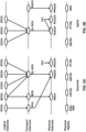
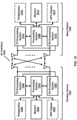
- FIG. 5A and FIG. 5B illustrate, for downlink and uplink respectively, a mapping between logical channels, transport channels, and physical channels.
- Information is passed through channels between the RLC, the MAC, and the PHY of the NR protocol stack.
- a logical channel may be used between the RLC and the MAC and may be classified as a control channel that carries control and configuration information in the NR control plane or as a traffic channel that carries data in the NR user plane.
- a logical channel may be classified as a dedicated logical channel that is dedicated to a specific UE or as a common logical channel that may be used by more than one UE.
- a logical channel may also be defined by the type of information it carries.
- the set of logical channels defined by NR include, for example:
- a BS may configure a UE with one or more resource sets for one or more PUCCH transmissions.
- a UE may receive downlink receptions (e.g., PDCCH or PDSCH) in a downlink BWP according to a configured numerology (e.g., subcarrier spacing and cyclic prefix duration) for the downlink BWP.
- the UE may transmit uplink transmissions (e.g., PUCCH or PUSCH) in an uplink BWP according to a configured numerology (e.g., subcarrier spacing and cyclic prefix length for the uplink BWP).
- the SCells may be configured after the PCell is configured for the UE.
- an SCell may be configured through an RRC Connection Reconfiguration procedure.
- the carrier corresponding to an SCell may be referred to as a downlink secondary CC (DL SCC).
- DL SCC downlink secondary CC
- UL SCC uplink secondary CC
- the SIB1 may contain information needed by the UE to access the cell.
- the UE may use one or more parameters of the MIB to monitor PDCCH, which may be used to schedule PDSCH.
- the PDSCH may include the SIB 1.
- the SIB 1 may be decoded using parameters provided in the MIB.
- the PBCH may indicate an absence of SIB 1. Based on the PBCH indicating the absence of SIB 1, the UE may be pointed to a frequency. The UE may search for an SS/PBCH block at the frequency to which the UE is pointed.
- a base station may transmit a plurality of SS/PBCH blocks.
- a first PCI of a first SS/PBCH block of the plurality of SS/PBCH blocks may be different from a second PCI of a second SS/PBCH block of the plurality of SS/PBCH blocks.
- the PCIs of SS/PBCH blocks transmitted in different frequency locations may be different or the same.
- a DMRS configuration may support up to eight orthogonal downlink DMRS ports per UE.
- a DMRS configuration may support up to 4 orthogonal downlink DMRS ports per UE.
- a radio network may support (e.g., at least for CP-OFDM) a common DMRS structure for downlink and uplink, wherein a DMRS location, a DMRS pattern, and/or a scrambling sequence may be the same or different.
- the base station may transmit a downlink DMRS and a corresponding PDSCH using the same precoding matrix.
- the UE may use the one or more downlink DMRSs for coherent demodulation/channel estimation of the PDSCH.
- Uplink PT-RS (which may be used by a base station for phase tracking and/or phase-noise compensation) may or may not be present depending on an RRC configuration of the UE.
- the presence and/or pattern of uplink PT-RS may be configured on a UE-specific basis by a combination of RRC signaling and/or one or more parameters employed for other purposes (e.g., Modulation and Coding Scheme (MCS)), which may be indicated by DCI.
- MCS Modulation and Coding Scheme
- a dynamic presence of uplink PT-RS may be associated with one or more DCI parameters comprising at least MCS.
- a radio network may support a plurality of uplink PT-RS densities defined in time/frequency domain.
- At least one DCI format may be employed for the UE to select at least one of one or more configured SRS resource sets.
- An SRS trigger type 0 may refer to an SRS triggered based on a higher layer signaling.
- An SRS trigger type 1 may refer to an SRS triggered based on one or more DCI formats.
- the UE when PUSCH and SRS are transmitted in a same slot, the UE may be configured to transmit SRS after a transmission of a PUSCH and a corresponding uplink DMRS.
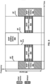
- the three beams illustrated in FIG. 11B may be configured for a UE in a UE-specific configuration. Three beams are illustrated in FIG. 11B (beam #1, beam #2, and beam #3), more or fewer beams may be configured.
- Beam #1 may be allocated with CSI-RS 1101 that may be transmitted in one or more subcarriers in an RB of a first symbol.
- Beam #2 may be allocated with CSI-RS 1102 that may be transmitted in one or more subcarriers in an RB of a second symbol.
- Beam #3 may be allocated with CSI-RS 1103 that may be transmitted in one or more subcarriers in an RB of a third symbol.
- a base station may use other subcarriers in a same RB (for example, those that are not used to transmit CSI-RS 1101) to transmit another CSI-RS associated with a beam for another UE.
- FDM frequency division multiplexing
- TDM time domain multiplexing
- CSI-RSs such as those illustrated in FIG. 11B (e.g., CSI-RS 1101, 1102, 1103) may be transmitted by the base station and used by the UE for one or more measurements.
- the UE may measure a reference signal received power (RSRP) of configured CSI-RS resources.
- the base station may configure the UE with a reporting configuration and the UE may report the RSRP measurements to a network (for example, via one or more base stations) based on the reporting configuration.
- the base station may determine, based on the reported measurement results, one or more transmission configuration indication (TCI) states comprising a number of reference signals.
- TCI transmission configuration indication
- the base station may indicate one or more TCI states to the UE (e.g., via RRC signaling, a MAC CE, and/or a DCI).
- the UE may receive a downlink transmission with a receive (Rx) beam determined based on the one or more TCI states.
- the UE may or may not have a capability of beam correspondence. If the UE has the capability of beam correspondence, the UE may determine a spatial domain filter of a transmit (Tx) beam based on a spatial domain filter of the corresponding Rx beam. If the UE does not have the capability of beam correspondence, the UE may perform an uplink beam selection procedure to determine the spatial domain filter of the Tx beam.
- the UE may perform the uplink beam selection procedure based on one or more sounding reference signal (SRS) resources configured to the UE by the base station.
- the base station may select and indicate uplink beams for the UE based on measurements of the one or more SRS resources transmitted by the UE.
- SRS sounding reference signal
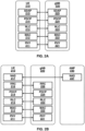
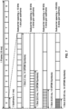
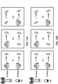
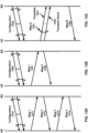
- FIG. 12A illustrates examples of three downlink beam management procedures: P1, P2, and P3.
- Procedure P1 may enable a UE measurement on transmit (Tx) beams of a transmission reception point (TRP) (or multiple TRPs), e.g., to support a selection of one or more base station Tx beams and/or UE Rx beams (shown as ovals in the top row and bottom row, respectively, of P1).
- Beamforming at a TRP may comprise a Tx beam sweep for a set of beams (shown, in the top rows of P1 and P2, as ovals rotated in a counter-clockwise direction indicated by the dashed arrow).
- Beamforming at a UE may comprise an Rx beam sweep for a set of beams (shown, in the bottom rows of P1 and P3, as ovals rotated in a clockwise direction indicated by the dashed arrow).
- Procedure P2 may be used to enable a UE measurement on Tx beams of a TRP (shown, in the top row of P2, as ovals rotated in a counter-clockwise direction indicated by the dashed arrow).
- the UE and/or the base station may perform procedure P2 using a smaller set of beams than is used in procedure P1, or using narrower beams than the beams used in procedure P1. This may be referred to as beam refinement.
- the UE may perform procedure P3 for Rx beam determination by using the same Tx beam at the base station and sweeping an Rx beam at the UE.
- FIG. 12B illustrates examples of three uplink beam management procedures: U1, U2, and U3.
- Procedure U1 may be used to enable a base station to perform a measurement on Tx beams of a UE, e.g., to support a selection of one or more UE Tx beams and/or base station Rx beams (shown as ovals in the top row and bottom row, respectively, of U1).
- Beamforming at the UE may include, e.g., a Tx beam sweep from a set of beams (shown in the bottom rows of U1 and U3 as ovals rotated in a clockwise direction indicated by the dashed arrow).
- Beamforming at the base station may include, e.g., an Rx beam sweep from a set of beams (shown, in the top rows of U1 and U2, as ovals rotated in a counter-clockwise direction indicated by the dashed arrow).
- Procedure U2 may be used to enable the base station to adjust its Rx beam when the UE uses a fixed Tx beam.
- the UE and/or the base station may perform procedure U2 using a smaller set of beams than is used in procedure P1, or using narrower beams than the beams used in procedure P1. This may be referred to as beam refinement
- the UE may perform procedure U3 to adjust its Tx beam when the base station uses a fixed Rx beam.
- the UE may measure a quality of a beam pair link using one or more reference signals (RSs) comprising one or more SS/PBCH blocks, one or more CSI-RS resources, and/or one or more demodulation reference signals (DMRSs).
- RSs reference signals
- a quality of the beam pair link may be based on one or more of a block error rate (BLER), an RSRP value, a signal to interference plus noise ratio (SINR) value, a reference signal received quality (RSRQ) value, and/or a CSI value measured on RS resources.
- the base station may indicate that an RS resource is quasi co-located (QCLed) with one or more DM-RSs of a channel (e.g., a control channel, a shared data channel, and/or the like).
- the RS resource and the one or more DMRSs of the channel may be QCLed when the channel characteristics (e.g., Doppler shift, Doppler spread, average delay, delay spread, spatial Rx parameter, fading, and/or the like) from a transmission via the RS resource to the UE are similar or the same as the channel characteristics from a transmission via the channel to the UE.
- the channel characteristics e.g., Doppler shift, Doppler spread, average delay, delay spread, spatial Rx parameter, fading, and/or the like
- a network e.g., a gNB and/or an ng-eNB of a network
- the UE may initiate a random access procedure.
- a UE in an RRC_IDLE state and/or an RRC_INACTIVE state may initiate the random access procedure to request a connection setup to a network.
- the UE may initiate the random access procedure from an RRC_CONNECTED state.
- the UE may initiate the random access procedure to request uplink resources (e.g., for uplink transmission of an SR when there is no PUCCH resource available) and/or acquire uplink timing (e.g., when uplink synchronization status is non-synchronized).
- the UE may initiate the random access procedure to request one or more system information blocks (SIBs) (e.g., other system information such as SIB2, SIB3, and/or the like).
- SIBs system information blocks
- the UE may initiate the random access procedure for a beam failure recovery request.
- a network may initiate a random access procedure for a handover and/or for establishing time alignment for an SCell addition.
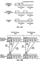
- FIG. 13A illustrates a four-step contention-based random access procedure.
- a base station may transmit a configuration message 1310 to the UE.
- the procedure illustrated in FIG. 13A comprises transmission of four messages: a Msg 1 1311, a Msg 2 1312, a Msg 3 1313, and a Msg 4 1314.
- the Msg 1 1311 may include and/or be referred to as a preamble (or a random access preamble).
- the Msg 2 1312 may include and/or be referred to as a random access response (RAR).
- RAR random access response
- the configuration message 1310 may be transmitted, for example, using one or more RRC messages.
- the one or more RRC messages may indicate one or more random access channel (RACH) parameters to the UE.
- the one or more RACH parameters may comprise at least one of following: general parameters for one or more random access procedures (e.g., RACH-configGeneral); cell-specific parameters (e.g., RACH-ConfigCommon); and/or dedicated parameters (e.g., RACH-configDedicated).
- the base station may broadcast or multicast the one or more RRC messages to one or more UEs.
- the one or more RRC messages may be UE-specific (e.g., dedicated RRC messages transmitted to a UE in an RRC_CONNECTED state and/or in an RRC_INACTIVE state).
- the UE may determine, based on the one or more RACH parameters, a time-frequency resource and/or an uplink transmit power for transmission of the Msg 1 1311 and/or the Msg 3 1313. Based on the one or more RACH parameters, the UE may determine a reception timing and a downlink channel for receiving the Msg 2 1312 and the Msg 4 1314.
- the one or more RACH parameters provided in the configuration message 1310 may be used to determine an uplink transmit power of Msg 1 1311 and/or Msg 3 1313.
- the one or more RACH parameters may indicate a reference power for a preamble transmission (e.g., a received target power and/or an initial power of the preamble transmission).
- the one or more RACH parameters may indicate: a power ramping step; a power offset between SSB and CSI-RS; a power offset between transmissions of the Msg 1 1311 and the Msg 3 1313; and/or a power offset value between preamble groups.
- the one or more RACH parameters may indicate one or more thresholds based on which the UE may determine at least one reference signal (e.g., an SSB and/or CSI-RS) and/or an uplink carrier (e.g., a normal uplink (NUL) carrier and/or a supplemental uplink (SUL) carrier).
- at least one reference signal e.g., an SSB and/or CSI-RS
- an uplink carrier e.g., a normal uplink (NUL) carrier and/or a supplemental uplink (SUL) carrier.
- the UE may measure an RSRP of one or more reference signals (e.g., SSBs and/or CSI-RSs) and determine at least one reference signal having an RSRP above an RSRP threshold (e.g., rsrp-ThresholdSSB and/or rsrp-ThresholdCSI-RS).
- the UE may select at least one preamble associated with the one or more reference signals and/or a selected preamble group, for example, if the association between the one or more preambles and the at least one reference signal is configured by an RRC message.
- the UE may determine the preamble based on the one or more RACH parameters provided in the configuration message 1310. For example, the UE may determine the preamble based on a pathloss measurement, an RSRP measurement, and/or a size of the Msg 3 1313.
- the one or more RACH parameters may indicate: a preamble format; a maximum number of preamble transmissions; and/or one or more thresholds for determining one or more preamble groups (e.g., group A and group B).
- a base station may use the one or more RACH parameters to configure the UE with an association between one or more preambles and one or more reference signals (e.g., SSBs and/or CSI-RSs).
- the UE may determine the preamble to include in Msg 1 1311 based on the association.
- the Msg 1 1311 may be transmitted to the base station via one or more PRACH occasions.
- the UE may use one or more reference signals (e.g., SSBs and/or CSI-RSs) for selection of the preamble and for determining of the PRACH occasion.
- One or more RACH parameters e.g., ra-ssb-OccasionMskIndex and/or ra-OccasionList
- ra-ssb-OccasionMskIndex and/or ra-OccasionList may indicate an association between the PRACH occasions and the one or more reference signals.
- the UE may perform a preamble retransmission if no response is received following a preamble transmission.
- the UE may increase an uplink transmit power for the preamble retransmission.
- the UE may select an initial preamble transmit power based on a pathloss measurement and/or a target received preamble power configured by the network.
- the UE may determine to retransmit a preamble and may ramp up the uplink transmit power.
- the UE may receive one or more RACH parameters (e.g., PREAMBLE_POWER_RAMPING_STEP) indicating a ramping step for the preamble retransmission.
- the ramping step may be an amount of incremental increase in uplink transmit power for a retransmission.
- the UE may ramp up the uplink transmit power if the UE determines a reference signal (e.g., SSB and/or CSI-RS) that is the same as a previous preamble transmission.
- the UE may count a number of preamble transmissions and/or retransmissions (e.g., PREAMBLE_TRANSMISSION_COUNTER).
- the UE may determine that a random access procedure completed unsuccessfully, for example, if the number of preamble transmissions exceeds a threshold configured by the one or more RACH parameters (e.g., preambleTransMax).
- the Msg 2 1312 may include a time-alignment command that may be used by the UE to adjust the UE's transmission timing, a scheduling grant for transmission of the Msg 3 1313, and/or a Temporary Cell RNTI (TC-RNTI).
- TC-RNTI Temporary Cell RNTI
- the UE may start a time window (e.g., ra-ResponseWindow) to monitor a PDCCH for the Msg 2 1312.
- the UE may determine when to start the time window based on a PRACH occasion that the UE uses to transmit the preamble.
- the UE may start the time window one or more symbols after a last symbol of the preamble (e.g., at a first PDCCH occasion from an end of a preamble transmission).
- the one or more symbols may be determined based on a numerology.
- the PDCCH may be in a common search space (e.g., a Type1-PDCCH common search space) configured by an RRC message.
- the UE may identify the RAR based on a Radio Network Temporary Identifier (RNTI). RNTIs may be used depending on one or more events initiating the random access procedure.
- the UE may use random access RNTI (RA-RNTI).
- the RA-RNTI may be associated with PRACH occasions in which the UE transmits a preamble.
- the UE may determine the RA-RNTI based on: an OFDM symbol index; a slot index; a frequency domain index; and/or a UL carrier indicator of the PRACH occasions.
- the UE may transmit the Msg 3 1313 in response to a successful reception of the Msg 2 1312 (e.g., using resources identified in the Msg 2 1312).
- the Msg 3 1313 may be used for contention resolution in, for example, the contention-based random access procedure illustrated in FIG. 13A .
- a plurality of UEs may transmit a same preamble to a base station and the base station may provide an RAR that corresponds to a UE. Collisions may occur if the plurality of UEs interpret the RAR as corresponding to themselves.
- the UE may switch an uplink carrier during the random access procedure (e.g., between the Msg 1 1311 and the Msg 3 1313) in one or more cases. For example, the UE may determine and/or switch an uplink carrier for the Msg 1 1311 and/or the Msg 3 1313 based on a channel clear assessment (e.g., a listen-before-talk).
- a channel clear assessment e.g., a listen-before-talk.
- the Msg B 1332 may comprise contents that are similar and/or equivalent to the contents of the Msg 2 1312 (e.g., an RAR) illustrated in FIGS. 13A and 13B and/or the Msg 4 1314 illustrated in FIG. 13A .
- the UE may initiate the two-step random access procedure in FIG. 13C for licensed spectrum and/or unlicensed spectrum.
- the UE may determine, based on one or more factors, whether to initiate the two-step random access procedure.
- the one or more factors may be: a radio access technology in use (e.g., LTE, NR, and/or the like); whether the UE has valid TA or not; a cell size; the UE's RRC state; a type of spectrum (e.g., licensed vs. unlicensed); and/or any other suitable factors.
- the UE may determine, based on two-step RACH parameters included in the configuration message 1330, a radio resource and/or an uplink transmit power for the preamble 1341 and/or the transport block 1342 included in the Msg A 1331.
- the RACH parameters may indicate a modulation and coding schemes (MCS), a time-frequency resource, and/or a power control for the preamble 1341 and/or the transport block 1342.
- MCS modulation and coding schemes
- a time-frequency resource for transmission of the preamble 1341 e.g., a PRACH
- a time-frequency resource for transmission of the transport block 1342 e.g., a PUSCH
- the RACH parameters may enable the UE to determine a reception timing and a downlink channel for monitoring for and/or receiving Msg B 1332.
- a base station may attach one or more cyclic redundancy check (CRC) parity bits to a DCI in order to facilitate detection of transmission errors.
- CRC cyclic redundancy check
- the base station may scramble the CRC parity bits with an identifier of the UE (or an identifier of the group of the UEs). Scrambling the CRC parity bits with the identifier may comprise Modulo-2 addition (or an exclusive OR operation) of the identifier value and the CRC parity bits.
- the identifier may comprise a 16-bit value of a radio network temporary identifier (RNTI).
- RNTI radio network temporary identifier
- the base station may transmit the DCIs with one or more DCI formats.
- DCI format 0_0 may be used for scheduling of PUSCH in a cell.
- DCI format 0_0 may be a fallback DCI format (e.g., with compact DCI payloads).
- DCI format 0_1 may be used for scheduling of PUSCH in a cell (e.g., with more DCI payloads than DCI format 0_0).
- DCI format 1_0 may be used for scheduling of PDSCH in a cell.
- DCI format 1_0 may be a fallback DCI format (e.g., with compact DCI payloads).
- DCI format 1_1 may be used for scheduling of PDSCH in a cell (e.g., with more DCI payloads than DCI format 1_0).
- DCI format 2_0 may be used for providing a slot format indication to a group of UEs.
- DCI format 2_1 may be used for notifying a group of UEs of a physical resource block and/or OFDM symbol where the UE may assume no transmission is intended to the UE.
- DCI format 2_2 may be used for transmission of a transmit power control (TPC) command for PUCCH or PUSCH.
- DCI format 2_3 may be used for transmission of a group of TPC commands for SRS transmissions by one or more UEs.
- DCI format(s) for new functions may be defined in future releases.
- DCI formats may have different DCI sizes, or may share the same DCI size.
- the base station may transmit, to the UE, RRC messages comprising configuration parameters of one or more CORESETs and one or more search space sets.
- the configuration parameters may indicate an association between a search space set and a CORESET.
- a search space set may comprise a set of PDCCH candidates formed by CCEs at a given aggregation level.
- the configuration parameters may indicate: a number of PDCCH candidates to be monitored per aggregation level; a PDCCH monitoring periodicity and a PDCCH monitoring pattern; one or more DCI formats to be monitored by the UE; and/or whether a search space set is a common search space set or a UE-specific search space set.
- a set of CCEs in the common search space set may be predefined and known to the UE.
- a set of CCEs in the UE-specific search space set may be configured based on the UE's identity (e.g., C-RNTI).
- the base station may transmit configuration parameters to the UE for a plurality of PUCCH resource sets using, for example, an RRC message.
- the plurality of PUCCH resource sets (e.g., up to four sets) may be configured on an uplink BWP of a cell.
- a PUCCH resource set may be configured with a PUCCH resource set index, a plurality of PUCCH resources with a PUCCH resource being identified by a PUCCH resource identifier (e.g., pucch-Resourceid), and/or a number (e.g. a maximum number) of UCI information bits the UE may transmit using one of the plurality of PUCCH resources in the PUCCH resource set.
- a PUCCH resource identifier e.g., pucch-Resourceid
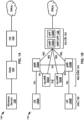
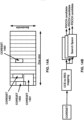
- a reception processing system 1512 may receive the uplink transmission from the wireless device 1502.
- a reception processing system 1522 may receive the downlink transmission from base station 1504.
- the reception processing system 1512 and the reception processing system 1522 may implement layer 1 OSI functionality.
- Layer 1 may include a PHY layer with respect to FIG. 2A, FIG. 2B , FIG. 3 , and FIG. 4A .
- the PHY layer may perform, for example, error detection, forward error correction decoding, deinterleaving, demapping of transport channels to physical channels, demodulation of physical channels, MIMO or multi-antenna processing, and/or the like.
- the UE-RRC layer Based on the security keys/parameters, the UE-RRC layer derive new security keys for integrity protection and ciphering, and configure lower layers (e.g. MAC layer) to apply them.
- the UE-RRC layer may re-establish PDCP entities for SRB1 and resume SRB1.
- the UE may verify that the integrity of the received RRC release message comprising the suspend configuration parameters is correct by checking PDCP MAC-I. If this verification is successful, then the UE may take the received NCC value and save it as stored NCC with the current UE context. The UE may delete the current AS keys K RRCenc , K UPenc , and K UPint , but keep the current AS key K RRCint key. If the stored NCC value is different from the NCC value associated with the current K gNB , the UE may delete the current AS key K gNB .
- the UE in RRC inactive state may initiate an RRC connection resume procedure. For example, based on having data or signaling to transmit, or receiving RAN paging message, the UE in RRC inactive state may initiate the RRC connection resume procedure. Based on initiating the RRC connection resume procedure, the UE may select access category based on triggering condition of the RRC connection resume procedure and perform unified access control procedure based on the access category. Based on the unified access control procedure, the UE may consider access attempt for the RRC connection resume procedure as allowed.
- the target base station may send an RRC release message to the UE. For example, based on the retrieve UE context failure message comprising the RRC release message, the target base station may send the RRC release message to the UE. Based on receiving the retrieve UE context failure message, the target base station may send an RRC setup message or an RRC reject message. Based on receiving the retrieve UE context failure message, the target base station may not send any response message to the UE.
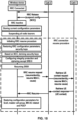
- FIG. 19 illustrates an example of an RRC connection resume procedure with anchor relocation.
- a UE e.g., a wireless device
- An old base station e.g., anchor base station or first base station or source base station
- the RRC release message may request the UE to be in RRC inactive state.
- the anchor base station may send the RRC release message comprising the suspend configuration parameters to the UE.
- the anchor base station may store current UE configuration parameters and the suspend configuration parameters into UE context (e.g., UE inactive AS context) and transition to an RRC inactive state.
- UE context e.g., UE inactive AS context
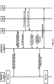
- FIG. 22 illustrates an example of a user plane early data transmission procedure with anchor relocation.
- a UE e.g., a wireless device
- An old base station e.g., an anchor base station
- the anchor base station may have no connection for transmitting/receiving control signaling of the UE with an AMF and/or no connection for transmitting/receiving user data of the UE with an UPF.
- the anchor base station may have them.
- the UE may send an RRC resume request message to a new base station (e.g., a target base station).
- the RRC resume request message may comprise UL data and/or AS RAI (e.g., RAI of the AS layer).
- the UE may send the RRC resume message via CCCH, the UL data via DTCH and the AS RAI via MAC CE.
- the UE may multiplex the RRC resume message, the UL data and the AS RAI.
- the AS RAI may comprise at least one of: (a) no further uplink and no further downlink data transmission is expected; (b) a single downlink data transmission and no further uplink data transmission is expected; or (c) more than single uplink or downlink data transmission is expected.
- the new base station may transmit uplink data to the UPF and receive downlink data of the UE from the UPF.
- a connection (e.g., N3 connection) for a path (A) may be released and the first base station and a UPF may store information for the connection (e.g., address for the connection).
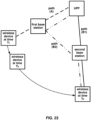
- the UE in the RRC inactive state or the RRC idle state with suspending RRC connection may perform a cell selection procedure. Based on the cell selection procedure, the UE may select a cell of a second base station and camp on the cell. The UE may perform an RRC resume procedure by sending an RRC resume procedure at time T3. For uplink data and downlink data transmission/reception of the UE, a most direct path (B1) may be considered as optimal path.
- the anchor (base station) of the UE may need to be relocated from the first base station to the second base station by sending UE context from the first base station to the second base station.
- the anchor relocation may trigger a path switch procedure indicating the anchor relocation to core network entities (e.g., AMF and UPF).
- core network entities e.g., AMF and UPF.
- uplink data and down data may be transmitted/received via the path (B1).
- signaling for the anchor relocation procedure and the path switch procedure may be necessary.
- data transmission/reception may be delayed until completion of the anchor relocation procedure and the path switch procedure.
- the UE may have small amount of uplink/down data.
- transmission/reception via an indirect path (B2) may be optimal in some scenarios. For example, if there is a small amount of data to be transmitted, then the signaling and delay associated with switching to path (B 1) may not be justified.
- an old base station e.g., anchor base station
- an old base station that stores/keeps a context of the wireless device in an RRC inactive state may receive a retrieve UE context request message from the new base station.
- the old base station may determine to relocate the context to the new base station. If the size of data to communicate for the wireless device is small, relocating context of the wireless device from an old base station to a new base station may not be efficient. Relocation of context may increase signaling and latency of the data transmission.
- the old base station may determine to keep the context.
- the old base station may send an RRC release message to the wireless device via the new base station based on the determining.
- the old base station may receive downlink data from the core network (e.g., downlink data for the wireless device).
- the old base station may need to perform a paging procedure, which increases signaling.
- Existing technologies may increase inefficient signaling and data transmission delay.
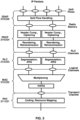
- Example embodiments of the present disclosure are directed to an enhanced procedure for transmission of small amounts of data. Whereas existing technologies continue to have high latency and signaling overheads for data transmission, example embodiments leverage (AS) RAI and downlink data information to more efficiently transmit/receive small data.
- AS AS
- a new base station may send to an anchor base station a retrieve UE context request message comprising assistance information (e.g., small data transmission assistance information). Based on the assistance information, the anchor base station may determine whether to relocate a context of a wireless device. This may reduce signaling and latency of data transmission/reception due to relocating of the context of the wireless device. Based on the assistance information, the anchor base station may determine whether to wait to receive downlink data of the wireless device from a core network entity. Based on determining to wait to receive the downlink data, the anchor base station may postpone to send an RRC release message for the wireless device until receiving downlink data. This may reduce unnecessary signaling for example, due to paging procedure which increases latency of downlink data transmission to the wireless device. Based on determining not to wait for the downlink data, the anchor base station may send an RRC release message to the wireless device via the new base station. This may decrease time of the small data transmission which reduces power consumption of the wireless device.
- assistance information e.g., small data transmission assistance information
- a base station which has data of a wireless device to transmit to another base station may perform a tunnel establishment procedure (e.g., tunnel address request and response) while postponing sending of the data until a user plane tunnel is established.
- a new base station that receives uplink data (e.g., small data) and an RRC request message from a wireless device may send a retrieve UE context request message to an old base station (e.g., anchor base station) that stores/keeps the context of the wireless device.
- the new base station may postpone sending of the uplink data to the anchor base station until the user plane tunnel for the small uplink data is established, causing delay of sending the uplink data to an application server via a core network entity.
- the delayed uplink data may cause delay of downlink data, in response to the uplink data, which is sent by the application server to the anchor base station.
- the wireless device may need to monitor downlink channel until receiving the delayed downlink data. This may increase power consumption of the wireless device.
- the anchor base station receiving the downlink data from the core network entity may postpone sending of the downlink data to the new base station until a user plane tunnel for the downlink data is established. This may cause signaling and latency for transmission of the downlink data.
- the wireless device may need to monitor downlink channel until receiving the delayed downlink data. This may increase power consumption of the wireless device.
- Example embodiments enable a base station to send data to another base station without the delay for establishing user tunnel between base stations.
- a new base station may send to an anchor base station a retrieve UE context request message comprising uplink data (e.g., when size of the uplink data is small). This may reduce the delay of uplink data transmission to the core network entity.
- the anchor base station may send to the new base station a retrieve UE context failure message comprising downlink data when receiving the downlink data from a core network entity. This may reduce the delay of downlink data transmission to a wireless device.
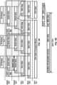
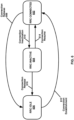
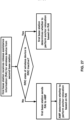
- FIG. 24 illustrates an example diagram showing an enhanced procedure for small data transmission without anchor relocation in RRC inactive state.
- a first base station e.g., old base station or anchor base station or source station
- RAI release assistance information
- the first base station may determine whether to perform anchor relocation for the UE or not.
- the first base station may send a retrieve UE context response message comprising UE context of the UE to the second base station.
- the first base station may send a retrieve UE context failure message comprising an RRC release message to the second base station.
- RAI may indicate that a downlink data transmission is expected (e.g., a single downlink data transmission and no further uplink data transmission is expected).
- the first base station may wait for downlink data from the UPF.
- the first base station may determine not to perform anchor relocation.
- the first base station may send a retrieve UE context failure message comprising an RRC release message wherein the RRC release message may comprise the downlink data.
- RAI may comprise expected data transmission information.
- the expected data transmission information may comprise at least one of: (a) no further uplink and no further downlink data transmission is expected; (b) a single downlink data transmission and no further uplink data transmission is expected; or (c) more than single uplink or downlink data transmission is expected.
- RAI may indicate that no further data transmission is expected (e.g., no further uplink and no further downlink data transmission is expected). Based on the RAI, the first base station may not wait downlink data from the UPF and send the retrieve UE context failure message comprising the RRC release message.
- RAI may indicate neither that no data transmission is expected nor that single downlink data transmission is expected (e.g., more than single uplink or downlink data transmission is expected).
- the first base station may determine to perform anchor relocation by sending the retrieve UE context response message comprising UE context of the UE.
- the first base station may not receive RAI. Based on not having RAI, the first base station may determine to perform anchor relocation by sending the retrieve UE context response message comprising UE context of the UE.
- the second base station may forward the RRC release message to the UE.
- the UE may transition to an RRC inactive or an RRC idle state (with suspending RRC connection).
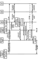
- FIG. 25 illustrates an example of an enhanced procedure for mobile originated data transmission without anchor relocation in RRC inactive state.
- a wireless device or UE may be in a CM connected state and an RRC inactive state.
- An old base station e.g., anchor base station or first base station or source base station
- the UE may have stored UE context in UE inactive AS context.
- the UE may have small uplink data. Based on the small uplink data, the UE may determine to perform a user plane EDT procedure. Based on the determining, the UE may send an RRC resume request message, uplink (UL) data and (AS) RAI to a new base station (e.g., non-anchor base station or target base station or second base station).
- UL uplink
- AS AS
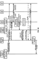
- FIG. 26 illustrates an example of an enhanced procedure for mobile terminated data transmission without anchor relocation in RRC inactive state.
- the data may be small data.
- a wireless device or UE may be CM connected state and an RRC inactive state.
- An old base station e.g., an anchor base station, a first base station
- the first base station may receive small downlink data.
- the first base station may determine to perform a user plane EDT procedure.
- the first base station may broadcast a paging message comprising mobile terminated (MT) EDT indication via one or more cells of the first base station and send the paging message to one or more base stations in RNA area.
- MT mobile terminated
- the base stations may broadcast the paging message via one or more cells of each base station.
- the UE may receive the paging message via a cell of a new base station (e.g., a new base station, a target base station, a second base station).
- the UE may determine to perform a user plane EDT procedure.
- the UE may send an RRC resume request message and (AS) RAI to the second base station.
- the second base station may send a retrieve UE context request message comprising the RAI.
- the RAI may indicate that no further data transmission is expected (e.g., no further uplink and no further downlink data transmission is expected).
- the first base station may send the retrieve UE context failure message comprising the RRC release message wherein the RRC release message may comprise the downlink data.
- the second base station may forward the RRC release message to the UE.
- the UE may transition to an RRC inactive or an RRC idle state (with suspending RRC connection).
- the data threshold may comprise a data threshold for uplink data transmission and a data threshold for downlink transmission.
- the data threshold for uplink data transmission may be used for uplink data and the data threshold for downlink data transmission may be used for downlink data.
- the first base station may determine not to perform anchor relocation.
- the RAI may comprise the data threshold.
- a second base station (and/or a UE and/or a first base station) may determine the data threshold based on at least one of signaling quality between the UE and the second base station, UE capability, expected arrival time of expected uplink/downlink data or expected resource for expected data transmission (e.g., expected time or amount of radio frequency resource or transmission power).
- the expected resource for expected data transmission may be determined based on the signaling quality and/or the UE capability.
- the UE may sends the UE capability, expected arrival time of expected uplink/downlink data and/or the expected resource for expected data transmission to the second base station and/or the first base station.
- the RAI may comprise at least one of signaling quality between the UE and the second base station, UE capability, expected arrival time of expected uplink/downlink data or expected resource for expected data transmission (e.g., expected time or amount of radio frequency resource frequency or transmission power).
- the second base station may start a timer with a timer value.
- the second base station may determine the timer value based on the RAI.
- the second base station may determine the timer value based on downlink data being expected and/or expected arrival time of the downlink data (e.g., round trip time of data transmission).
- the timer value may be preconfigured or determined in a UE and/or a base station.
- the timer value may be preconfigured or determined based on application information and/or data radio bearer identity.
- the second base station may start the timer with the timer value based on sending the retrieve UE context request message.
- the retrieve UE context request message may comprise the timer value.
- the first base station may start a timer with the timer value.
- the first base station may stop the timer.
- the first base station may send the response message (e.g., a retrieve UE context failure message).
- the first base station may send the response message.
- RAI may indicate that a downlink data transmission is expected (e.g., a single downlink data transmission and no further uplink data transmission is expected).
- the first base station may wait for the downlink data.
- the first base station may start the timer with the timer value.
- the first base station may determine anchor relocation. Based on the determining, the first base station may send a retrieve UE context response message comprising UE context of the UE.
- RAI may indicate that a downlink data transmission is expected (e.g., a single downlink data transmission and no further uplink data transmission is expected).
- the first base station may send a message indicating that downlink data is expected.
- the second base station may wait for response of the retrieve UE context request message and the downlink data.
- the second base station may stop the timer and restart the timer with the timer value.
- the first base station may receive downlink data from the UPF.
- the first base station may wait additional downlink data from the UPF.
- RAI may comprise amount of (expected) downlink data.
- the first base station may determine to wait additional downlink data from the UPF.
- the first base station may send a message comprising the first downlink data to the second base station.
- the message may indicate indicating that additional downlink data is expected.
- the second base station may wait for response of the retrieve UE context request message and the additional downlink data.
- the second base station may stop the timer and restart the timer with the timer value. Based on receiving the message comprising the first downlink data, the second base station may store the first downlink data in buffer. Based on receiving the message comprising the first downlink data, the second base station may send a radio message comprising the first downlink data to the UE. The radio message may indicate the additional downlink data is expected. Based on receiving the radio message, the UE may wait for the additional downlink data and keep monitoring downlink channel of the second base station.
- an old base station storing contexts of a wireless device may send RAI to AMF when receiving from a new base station a retrieve UE context request message comprising the RAI. Based on the RAI, the AMF may determine whether to perform anchor relocation or not. Based on the determining, the AMF may indicate the determining to the old base station. Based on the determining, the old base station may keep or provide the contexts of the wireless device. This may avoid unnecessary signals and delay due to anchor relocation between base stations and updating path/connection between a base station and core network entities. The reduce delay may reduce power consumption of a wireless device.
- the second base station may send a retrieve UE context request message to the first base station wherein the retrieve UE context message may comprise the UL data and the RAI.
- the first base station may send the UL data to the UPF.
- the first base station may send the UL data via the N3 connection of the UE to the UPF.
- the first base station may send a N2 resume request message comprising the RAI to an AMF.
- the AMF may determine to perform anchor relocation based on at least one of the RAI or downlink data information for pending downlink data.
- the AMF may determine to perform anchor relocation based on at least one of the RAI or downlink data information for pending downlink data. Based on the determining, the AMF may send a N2 resume response message to the first base station wherein the N2 resume response message may comprise a path switch response message. Based on receiving the path switch response message, the second base station may update the path for transmitting/receiving control signalling and user data of the UE. Based on receiving the path switch response message, the second base station may send a UE context release message to the first base station. Based on the UE context release message, the anchor may release the UE context. Based on the updated path, the second base station may forward uplink user data from the UE to the UPF and forward downlink data from the UPF to the UE.
- the anchor base station may provide the UE with different UE identities depending on RRC state by sending an RRC release message comprising the UE identity to the UE. For example, the anchor base station may provide the UE with a resume identity for RRC idle state with suspending RRC connection. Based on receiving the resume identity, the UE may transition to RRC idle state with suspending RRC connection. The UE may send an RRC resume request message comprising the resume identity to the anchor base station. The anchor base station may use the resume identity to identity the suspended UE context of the UE in RRC idle sate.
- the anchor base station may provide the UE with an inactive-RNTI (I-RNTI) for RRC inactive state. Based on receiving the I-RNTI, the UE may transition to RRC inactive state. The UE may send an RRC resume request message comprising the I-RNTI to the anchor base station. The anchor base station may use the I-RNTI to identity the suspended UE context of the UE in RRC inactive sate.
- I-RNTI inactive-RNTI
- the determining is based on the amount of expected data being smaller than the data threshold.
- the second message may be a retrieve UE context failure message.
- the AMF may send, to the first base station, the second N2 message based on the determining.
Landscapes
- Engineering & Computer Science (AREA)
- Computer Networks & Wireless Communication (AREA)
- Signal Processing (AREA)
- Databases & Information Systems (AREA)
- Mobile Radio Communication Systems (AREA)
Priority Applications (1)
| Application Number | Priority Date | Filing Date | Title |
|---|---|---|---|
| EP25213790.6A EP4683388A2 (de) | 2020-02-13 | 2021-02-12 | Kleindatenübertragung |
Applications Claiming Priority (3)
| Application Number | Priority Date | Filing Date | Title |
|---|---|---|---|
| US202062975900P | 2020-02-13 | 2020-02-13 | |
| EP21710722.6A EP4026391B1 (de) | 2020-02-13 | 2021-02-12 | Übertragung von kleinen daten (sdt) |
| PCT/US2021/017742 WO2021163394A1 (en) | 2020-02-13 | 2021-02-12 | Small data transmission (sdt) |
Related Parent Applications (2)
| Application Number | Title | Priority Date | Filing Date |
|---|---|---|---|
| EP21710722.6A Division-Into EP4026391B1 (de) | 2020-02-13 | 2021-02-12 | Übertragung von kleinen daten (sdt) |
| EP21710722.6A Division EP4026391B1 (de) | 2020-02-13 | 2021-02-12 | Übertragung von kleinen daten (sdt) |
Related Child Applications (1)
| Application Number | Title | Priority Date | Filing Date |
|---|---|---|---|
| EP25213790.6A Division EP4683388A2 (de) | 2020-02-13 | 2021-02-12 | Kleindatenübertragung |
Publications (2)
| Publication Number | Publication Date |
|---|---|
| EP4395413A2 true EP4395413A2 (de) | 2024-07-03 |
| EP4395413A3 EP4395413A3 (de) | 2024-08-28 |
Family
ID=74860464
Family Applications (3)
| Application Number | Title | Priority Date | Filing Date |
|---|---|---|---|
| EP24170187.9A Pending EP4395413A3 (de) | 2020-02-13 | 2021-02-12 | Übertragung von kleinen daten |
| EP21710722.6A Active EP4026391B1 (de) | 2020-02-13 | 2021-02-12 | Übertragung von kleinen daten (sdt) |
| EP25213790.6A Pending EP4683388A2 (de) | 2020-02-13 | 2021-02-12 | Kleindatenübertragung |
Family Applications After (2)
| Application Number | Title | Priority Date | Filing Date |
|---|---|---|---|
| EP21710722.6A Active EP4026391B1 (de) | 2020-02-13 | 2021-02-12 | Übertragung von kleinen daten (sdt) |
| EP25213790.6A Pending EP4683388A2 (de) | 2020-02-13 | 2021-02-12 | Kleindatenübertragung |
Country Status (9)
| Country | Link |
|---|---|
| US (4) | US11516873B2 (de) |
| EP (3) | EP4395413A3 (de) |
| JP (1) | JP7340212B2 (de) |
| KR (2) | KR20250111237A (de) |
| CN (3) | CN118785427A (de) |
| ES (1) | ES2986858T3 (de) |
| FI (1) | FI4026391T3 (de) |
| PL (1) | PL4026391T3 (de) |
| WO (1) | WO2021163394A1 (de) |
Families Citing this family (49)
| Publication number | Priority date | Publication date | Assignee | Title |
|---|---|---|---|---|
| BR112022005781A2 (pt) * | 2019-10-04 | 2022-06-21 | Ericsson Telefon Ab L M | Método para realizar transferência de pacotes de dados, equipamento de usuário, unidade de rede de acesso por rádio, e, meio de armazenamento legível por computador |
| CN118785427A (zh) | 2020-02-13 | 2024-10-15 | 佳能株式会社 | 小数据传输的方法、基站和介质 |
| EP4118805A4 (de) * | 2020-03-13 | 2023-11-08 | Lenovo (Beijing) Limited | Verfahren und vorrichtungen für kleine datenübertragung |
| CN113891345B (zh) * | 2020-07-03 | 2024-04-19 | 大唐移动通信设备有限公司 | 数据传输方法、指示方法及设备 |
| CN115885546A (zh) * | 2020-08-17 | 2023-03-31 | 瑞典爱立信有限公司 | 在非陆地网络中使用要服务的预期时间作为小区选择和重选标准 |
| BR102021016648A2 (pt) * | 2020-08-26 | 2022-03-08 | Nokia Technologies Oy | Realocação de contexto de equipamento de usuário na borda de área de notificação de rede de acesso de rádio |
| EP4214956A4 (de) | 2020-09-15 | 2024-02-21 | NEC Corporation | Verfahren, vorrichtung und computerspeichermedium zur kommunikation |
| EP3968696B1 (de) * | 2020-09-15 | 2026-02-18 | Nokia Technologies Oy | Ng-basierte kontextfreigabe und datenweiterleitung für multihop-mobilität |
| KR102687137B1 (ko) | 2020-09-24 | 2024-07-19 | 오피노 엘엘씨 | 소형 데이터 송신 완료 표시 |
| CN114598430B (zh) * | 2020-12-04 | 2026-02-24 | 维沃移动通信有限公司 | 随机接入方法、装置、终端及网络侧设备 |
| CN114745788A (zh) * | 2021-01-08 | 2022-07-12 | 北京三星通信技术研究有限公司 | 信息传输方法、装置、电子设备及存储介质 |
| EP4278749A4 (de) * | 2021-01-13 | 2024-02-28 | NEC Corporation | Verfahren, vorrichtungen und medium zur kommunikation |
| CN117397265A (zh) * | 2021-03-03 | 2024-01-12 | 欧芬诺有限责任公司 | 针对小数据传输的寻呼 |
| WO2022213962A1 (zh) * | 2021-04-06 | 2022-10-13 | 上海朗帛通信技术有限公司 | 一种被用于无线通信的方法和装置 |
| US11595869B2 (en) * | 2021-04-19 | 2023-02-28 | Verizon Patent And Licensing Inc. | System and method for enabling cell reselection |
| EP4114082B1 (de) * | 2021-06-30 | 2025-12-31 | Nokia Technologies Oy | Verfahren und vorrichtungen zur vermeidung von funkverbindungssteuerungskontextabruf in einer kleinen datenübertragung |
| US12432806B2 (en) * | 2021-08-03 | 2025-09-30 | Nokia Technologies Oy | Inactive user equipment verification for data transmission in communication network |
| WO2023028991A1 (en) * | 2021-09-03 | 2023-03-09 | Lenovo (Beijing) Limited | Method and apparatus for small data transmission |
| WO2023030887A1 (en) * | 2021-09-06 | 2023-03-09 | Nokia Technologies Oy | Methods and apparatuses for paging a terminal |
| JP7750398B2 (ja) * | 2021-09-14 | 2025-10-07 | 日本電気株式会社 | 第1のネットワーク装置、端末装置、及びそれらにより実行される方法 |
| WO2023048127A1 (en) * | 2021-09-21 | 2023-03-30 | Toyota Jidosha Kabushiki Kaisha | Quality of experience measurement in response to a resume procedure |
| EP4160937A1 (de) * | 2021-09-29 | 2023-04-05 | THALES DIS AIS Deutschland GmbH | Verwaltung der umleitung auf ein erdbasiertes netzwerk eines benutzergeräts |
| CN114026893A (zh) * | 2021-09-30 | 2022-02-08 | 北京小米移动软件有限公司 | 一种sdt传输方法、装置及存储介质 |
| CN116017502A (zh) * | 2021-10-22 | 2023-04-25 | 大唐移动通信设备有限公司 | 测量处理方法、装置及存储介质 |
| US20250008362A1 (en) * | 2021-11-19 | 2025-01-02 | Qualcomm Incorporated | Channel state information reports during a small data transfer session |
| US12363509B2 (en) | 2021-12-09 | 2025-07-15 | Acer Incorporated | Device and method for handling a reception of a multicast broadcast service transmission and a small data transmission |
| JP7781276B2 (ja) * | 2022-01-05 | 2025-12-05 | 中興通訊股▲ふん▼有限公司 | 非地上波無線通信方法、デバイスおよび記憶媒体 |
| WO2023130321A1 (zh) * | 2022-01-06 | 2023-07-13 | 北京小米移动软件有限公司 | 一种数据压缩方法和装置 |
| CN116489723A (zh) * | 2022-01-14 | 2023-07-25 | 荣耀终端有限公司 | 通信方法、装置及系统 |
| KR20240136992A (ko) * | 2022-01-27 | 2024-09-19 | 레노보(베이징)리미티드 | L2 u2n 릴레이의 경우에서의 타이머들 및 거동을 위한 방법들 및 장치들 |
| WO2023154443A1 (en) * | 2022-02-11 | 2023-08-17 | Google Llc | Managing a small data transmission configuration in mobility scenarios |
| US12490334B2 (en) * | 2022-03-01 | 2025-12-02 | Parsa Wireless Communications Llc | Multicasting using small data transmission |
| CN116782383A (zh) * | 2022-03-07 | 2023-09-19 | 展讯通信(上海)有限公司 | 一种寻呼方法及其装置 |
| US12604366B2 (en) * | 2022-03-18 | 2026-04-14 | Parsa Wireless Communications Llc | Multicast service delivery for use in inactive state |
| WO2023204752A1 (en) * | 2022-04-22 | 2023-10-26 | Telefonaktiebolaget Lm Ericsson (Publ) | Paging for mt-sdt - network control and inter-node signaling |
| CN117156461A (zh) * | 2022-05-24 | 2023-12-01 | 荣耀终端有限公司 | 网络配置方法、用户设备、网络设备及计算机存储介质 |
| CN117156500B (zh) * | 2022-05-24 | 2025-02-11 | 荣耀终端有限公司 | 数据传输方法、网络设备及计算机可读存储介质 |
| DE102022206907A1 (de) | 2022-07-06 | 2024-01-11 | Continental Automotive Technologies GmbH | Verfahren und Einrichtung zur robusten Übertragung kleiner Daten (Small Data Transmission) in einem drahtlosen Netzwerk |
| US20250386391A1 (en) * | 2022-07-15 | 2025-12-18 | Telefonaktiebolaget Lm Ericsson (Publ) | Mobile Terminated Small Data Transmission |
| DE102022207895A1 (de) | 2022-07-29 | 2024-02-01 | Continental Automotive Technologies GmbH | Verfahren und Einrichtung zur robusten Übertragung kleiner Daten (Small Data Transmission) in einem drahtlosen Netzwerk |
| CN117528803A (zh) * | 2022-07-29 | 2024-02-06 | 大唐移动通信设备有限公司 | 小数据传输方法、终端、网络设备、装置及存储介质 |
| CN117812676A (zh) * | 2022-09-30 | 2024-04-02 | 华为技术有限公司 | 一种数据传输方法及装置 |
| CN117858197A (zh) * | 2022-09-30 | 2024-04-09 | 华为技术有限公司 | 一种通信方法、通信装置及系统 |
| US12408082B2 (en) | 2022-09-30 | 2025-09-02 | T-Mobile Usa, Inc. | Reducing network traffic associated with a throughput intensive communication over a wireless telecommunication network |
| US20240121650A1 (en) * | 2022-10-10 | 2024-04-11 | Samsung Electronics Co., Ltd. | Method and apparatus for reporting measurement |
| JP2025532200A (ja) * | 2022-11-09 | 2025-09-29 | 楽天シンフォニー株式会社 | チャネル状態情報基準信号の送信 |
| EP4669015A4 (de) * | 2023-02-14 | 2026-04-01 | Beijing Xiaomi Mobile Software Co Ltd | Datenübertragungsverfahren und -vorrichtung sowie speichermedium |
| CN120226436A (zh) * | 2023-04-04 | 2025-06-27 | 中兴通讯股份有限公司 | Rrc非激活数据传输方法、设备及计算机可读存储介质 |
| US20250184067A1 (en) * | 2023-12-01 | 2025-06-05 | Qualcomm Incorporated | Network energy savings (nes) cell communications |
Family Cites Families (21)
| Publication number | Priority date | Publication date | Assignee | Title |
|---|---|---|---|---|
| CN101932019B (zh) | 2009-06-19 | 2015-06-03 | 中兴通讯股份有限公司 | 一种实现上报缓冲区状态报告的方法、终端及网络系统 |
| US20140146796A1 (en) | 2012-11-27 | 2014-05-29 | Qualcomm Incorporated | Buffer size reporting in time division high speed uplink packet access (td-hsupa) systems |
| WO2015005853A2 (en) | 2013-07-09 | 2015-01-15 | Telefonaktiebolaget L M Ericsson (Publ) | Method and apparatus in a telecommunication system |
| CN104349363B (zh) * | 2013-08-09 | 2017-11-24 | 上海贝尔股份有限公司 | 一种用于确定连接状态辅助参数的方法、设备与系统 |
| CN104936207A (zh) * | 2014-03-21 | 2015-09-23 | 上海贝尔股份有限公司 | 用于建立小数据传输连接的方法 |
| US10637701B2 (en) | 2015-06-04 | 2020-04-28 | Electronics And Telecommunications Research Institute | Method and apparatus for transmitting physical uplink control channel |
| WO2017095020A1 (ko) * | 2015-12-04 | 2017-06-08 | 엘지전자 주식회사 | 무선 통신 시스템에서 ue id를 전송하는 방법 및 장치 |
| PL4224983T3 (pl) * | 2017-02-03 | 2026-03-09 | Telefonaktiebolaget Lm Ericsson (Publ) | Wznowienie sterowania zasobami radiowymi bez pobierania kontekstu |
| WO2018214052A1 (en) * | 2017-05-24 | 2018-11-29 | Qualcomm Incorporated | Uplink small data transmission in inactive state |
| EP3711442B1 (de) * | 2017-11-16 | 2023-05-10 | Telefonaktiebolaget LM Ericsson (Publ) | Wiedergabeschutz für die wiederaufnahme eines verfahrens |
| EP3791688B1 (de) | 2018-05-10 | 2022-11-23 | IPLA Holdings Inc. | Übertragung kleiner datenmengen mit nichtorthogonalem mehrfachzugriff |
| AU2019316156B2 (en) | 2018-08-03 | 2022-05-12 | Telefonaktiebolaget Lm Ericsson (Publ) | User plane optimizations for 5G cellular internet of things |
| WO2020036460A1 (en) * | 2018-08-16 | 2020-02-20 | Lg Electronics Inc. | Method and apparatus for supporting early data transmission in inactive state in wireless communication system |
| WO2020064726A1 (en) | 2018-09-24 | 2020-04-02 | Telefonaktiebolaget Lm Ericsson (Publ) | User equipment (ue) reachability request parameter for suspended radio access network (ran) |
| WO2020087325A1 (en) | 2018-10-31 | 2020-05-07 | Qualcomm Incorporated | Data transmission with expiration time |
| US12022550B2 (en) * | 2019-03-15 | 2024-06-25 | Lg Electronics Inc. | Small data transmission without path switch procedure |
| US11419006B2 (en) * | 2019-07-29 | 2022-08-16 | Nokia Technologies Oy | User data transport over control plane in communication system using designated payload container types |
| US12225625B2 (en) * | 2019-11-22 | 2025-02-11 | Lenovo (Beijing) Ltd. | Method and apparatus for radio access network based notification area update |
| EP4094540A4 (de) * | 2020-01-22 | 2023-01-25 | NEC Corporation | Verfahren, vorrichtungen und medium zur kommunikation |
| US12245310B2 (en) * | 2020-01-22 | 2025-03-04 | Lg Electronics Inc. | Method and apparatus for fast small data transmission in a wireless communication system |
| CN118785427A (zh) * | 2020-02-13 | 2024-10-15 | 佳能株式会社 | 小数据传输的方法、基站和介质 |
-
2021
- 2021-02-12 CN CN202411162515.1A patent/CN118785427A/zh active Pending
- 2021-02-12 EP EP24170187.9A patent/EP4395413A3/de active Pending
- 2021-02-12 CN CN202411162518.5A patent/CN118785428A/zh active Pending
- 2021-02-12 EP EP21710722.6A patent/EP4026391B1/de active Active
- 2021-02-12 ES ES21710722T patent/ES2986858T3/es active Active
- 2021-02-12 KR KR1020257022953A patent/KR20250111237A/ko active Pending
- 2021-02-12 CN CN202180028080.XA patent/CN115486202B/zh active Active
- 2021-02-12 FI FIEP21710722.6T patent/FI4026391T3/fi active
- 2021-02-12 JP JP2022548914A patent/JP7340212B2/ja active Active
- 2021-02-12 EP EP25213790.6A patent/EP4683388A2/de active Pending
- 2021-02-12 KR KR1020227031489A patent/KR102833649B1/ko active Active
- 2021-02-12 WO PCT/US2021/017742 patent/WO2021163394A1/en not_active Ceased
- 2021-02-12 PL PL21710722.6T patent/PL4026391T3/pl unknown
-
2022
- 2022-04-07 US US17/715,180 patent/US11516873B2/en active Active
- 2022-10-25 US US17/972,920 patent/US11963250B2/en active Active
-
2024
- 2024-03-12 US US18/602,118 patent/US12418955B2/en active Active
-
2025
- 2025-08-19 US US19/303,667 patent/US20250374363A1/en active Pending
Also Published As
| Publication number | Publication date |
|---|---|
| CN115486202B (zh) | 2024-09-06 |
| KR20250111237A (ko) | 2025-07-22 |
| JP2023508232A (ja) | 2023-03-01 |
| US12418955B2 (en) | 2025-09-16 |
| JP7340212B2 (ja) | 2023-09-07 |
| US11963250B2 (en) | 2024-04-16 |
| ES2986858T3 (es) | 2024-11-12 |
| US11516873B2 (en) | 2022-11-29 |
| KR20220152229A (ko) | 2022-11-15 |
| WO2021163394A1 (en) | 2021-08-19 |
| EP4026391A1 (de) | 2022-07-13 |
| CN118785428A (zh) | 2024-10-15 |
| EP4026391B1 (de) | 2024-05-22 |
| US20230040076A1 (en) | 2023-02-09 |
| CN118785427A (zh) | 2024-10-15 |
| PL4026391T3 (pl) | 2024-10-28 |
| FI4026391T3 (fi) | 2024-06-18 |
| CN115486202A (zh) | 2022-12-16 |
| EP4395413A3 (de) | 2024-08-28 |
| EP4683388A2 (de) | 2026-01-21 |
| US20250374363A1 (en) | 2025-12-04 |
| US20220248493A1 (en) | 2022-08-04 |
| US20240224370A1 (en) | 2024-07-04 |
| KR102833649B1 (ko) | 2025-07-14 |
Similar Documents
| Publication | Publication Date | Title |
|---|---|---|
| US12418955B2 (en) | Small data transmission assistance information | |
| US12376184B2 (en) | Configuration of bandwidth part | |
| US12144057B2 (en) | Release message in small data transmission procedure | |
| US12225526B2 (en) | Release of configured grant | |
| US11723109B2 (en) | Downlink data of small data transmission procedure | |
| US12317149B2 (en) | Connection reestablishment procedure | |
| US12568536B2 (en) | Uplink data of small data transmission procedure |
Legal Events
| Date | Code | Title | Description |
|---|---|---|---|
| PUAI | Public reference made under article 153(3) epc to a published international application that has entered the european phase |
Free format text: ORIGINAL CODE: 0009012 |
|
| STAA | Information on the status of an ep patent application or granted ep patent |
Free format text: STATUS: THE APPLICATION HAS BEEN PUBLISHED |
|
| AC | Divisional application: reference to earlier application |
Ref document number: 4026391 Country of ref document: EP Kind code of ref document: P |
|
| AK | Designated contracting states |
Kind code of ref document: A2 Designated state(s): AL AT BE BG CH CY CZ DE DK EE ES FI FR GB GR HR HU IE IS IT LI LT LU LV MC MK MT NL NO PL PT RO RS SE SI SK SM TR |
|
| REG | Reference to a national code |
Ref country code: DE Ref legal event code: R079 Free format text: PREVIOUS MAIN CLASS: H04W0036000000 Ipc: H04W0076270000 Ref country code: DE Ref legal event code: R079 Ref document number: 602021054194 Country of ref document: DE Free format text: PREVIOUS MAIN CLASS: H04W0036000000 Ipc: H04W0076270000 |
|
| PUAL | Search report despatched |
Free format text: ORIGINAL CODE: 0009013 |
|
| AK | Designated contracting states |
Kind code of ref document: A3 Designated state(s): AL AT BE BG CH CY CZ DE DK EE ES FI FR GB GR HR HU IE IS IT LI LT LU LV MC MK MT NL NO PL PT RO RS SE SI SK SM TR |
|
| RIC1 | Information provided on ipc code assigned before grant |
Ipc: H04W 8/20 20090101ALN20240725BHEP Ipc: H04W 36/00 20090101ALI20240725BHEP Ipc: H04W 76/27 20180101AFI20240725BHEP |
|
| STAA | Information on the status of an ep patent application or granted ep patent |
Free format text: STATUS: REQUEST FOR EXAMINATION WAS MADE |
|
| 17P | Request for examination filed |
Effective date: 20250228 |
|
| GRAP | Despatch of communication of intention to grant a patent |
Free format text: ORIGINAL CODE: EPIDOSNIGR1 |
|
| STAA | Information on the status of an ep patent application or granted ep patent |
Free format text: STATUS: GRANT OF PATENT IS INTENDED |
|
| RIC1 | Information provided on ipc code assigned before grant |
Ipc: H04W 76/27 20180101AFI20250625BHEP Ipc: H04W 36/00 20090101ALI20250625BHEP Ipc: H04W 8/20 20090101ALN20250625BHEP |
|
| INTG | Intention to grant announced |
Effective date: 20250718 |
|
| GRAJ | Information related to disapproval of communication of intention to grant by the applicant or resumption of examination proceedings by the epo deleted |
Free format text: ORIGINAL CODE: EPIDOSDIGR1 |
|
| STAA | Information on the status of an ep patent application or granted ep patent |
Free format text: STATUS: REQUEST FOR EXAMINATION WAS MADE |
|
| GRAP | Despatch of communication of intention to grant a patent |
Free format text: ORIGINAL CODE: EPIDOSNIGR1 |
|
| STAA | Information on the status of an ep patent application or granted ep patent |
Free format text: STATUS: GRANT OF PATENT IS INTENDED |
|
| INTC | Intention to grant announced (deleted) | ||
| RIC1 | Information provided on ipc code assigned before grant |
Ipc: H04W 76/27 20180101AFI20251106BHEP Ipc: H04W 36/00 20090101ALI20251106BHEP Ipc: H04W 8/20 20090101ALN20251106BHEP |
|
| P01 | Opt-out of the competence of the unified patent court (upc) registered |
Free format text: CASE NUMBER: UPC_APP_0013541_4395413/2025 Effective date: 20251114 |
|
| RIC1 | Information provided on ipc code assigned before grant |
Ipc: H04W 76/27 20180101AFI20251120BHEP Ipc: H04W 36/00 20090101ALI20251120BHEP Ipc: H04W 8/20 20090101ALN20251120BHEP |
|
| INTG | Intention to grant announced |
Effective date: 20251201 |
|
| GRAS | Grant fee paid |
Free format text: ORIGINAL CODE: EPIDOSNIGR3 |
|
| GRAA | (expected) grant |
Free format text: ORIGINAL CODE: 0009210 |
|
| STAA | Information on the status of an ep patent application or granted ep patent |
Free format text: STATUS: THE PATENT HAS BEEN GRANTED |