EP4395291A1 - Elektronische vorrichtung mit flexibler anzeige und steuerungsverfahren für elektronische vorrichtung - Google Patents
Elektronische vorrichtung mit flexibler anzeige und steuerungsverfahren für elektronische vorrichtung Download PDFInfo
- Publication number
- EP4395291A1 EP4395291A1 EP23814078.4A EP23814078A EP4395291A1 EP 4395291 A1 EP4395291 A1 EP 4395291A1 EP 23814078 A EP23814078 A EP 23814078A EP 4395291 A1 EP4395291 A1 EP 4395291A1
- Authority
- EP
- European Patent Office
- Prior art keywords
- electronic device
- slide
- housing
- mode
- state
- Prior art date
- Legal status (The legal status is an assumption and is not a legal conclusion. Google has not performed a legal analysis and makes no representation as to the accuracy of the status listed.)
- Pending
Links
Images


Classifications
-
- G—PHYSICS
- G06—COMPUTING OR CALCULATING; COUNTING
- G06F—ELECTRIC DIGITAL DATA PROCESSING
- G06F3/00—Input arrangements for transferring data to be processed into a form capable of being handled by the computer; Output arrangements for transferring data from processing unit to output unit, e.g. interface arrangements
- G06F3/01—Input arrangements or combined input and output arrangements for interaction between user and computer
- G06F3/048—Interaction techniques based on graphical user interfaces [GUI]
- G06F3/0481—Interaction techniques based on graphical user interfaces [GUI] based on specific properties of the displayed interaction object or a metaphor-based environment, e.g. interaction with desktop elements like windows or icons, or assisted by a cursor's changing behaviour or appearance
- G06F3/04817—Interaction techniques based on graphical user interfaces [GUI] based on specific properties of the displayed interaction object or a metaphor-based environment, e.g. interaction with desktop elements like windows or icons, or assisted by a cursor's changing behaviour or appearance using icons
-
- G—PHYSICS
- G06—COMPUTING OR CALCULATING; COUNTING
- G06F—ELECTRIC DIGITAL DATA PROCESSING
- G06F3/00—Input arrangements for transferring data to be processed into a form capable of being handled by the computer; Output arrangements for transferring data from processing unit to output unit, e.g. interface arrangements
- G06F3/14—Digital output to display device ; Cooperation and interconnection of the display device with other functional units
-
- G—PHYSICS
- G06—COMPUTING OR CALCULATING; COUNTING
- G06F—ELECTRIC DIGITAL DATA PROCESSING
- G06F1/00—Details not covered by groups G06F3/00 - G06F13/00 and G06F21/00
- G06F1/16—Constructional details or arrangements
- G06F1/1613—Constructional details or arrangements for portable computers
- G06F1/1615—Constructional details or arrangements for portable computers with several enclosures having relative motions, each enclosure supporting at least one I/O or computing function
- G06F1/1624—Constructional details or arrangements for portable computers with several enclosures having relative motions, each enclosure supporting at least one I/O or computing function with sliding enclosures, e.g. sliding keyboard or display
-
- G—PHYSICS
- G06—COMPUTING OR CALCULATING; COUNTING
- G06F—ELECTRIC DIGITAL DATA PROCESSING
- G06F1/00—Details not covered by groups G06F3/00 - G06F13/00 and G06F21/00
- G06F1/16—Constructional details or arrangements
- G06F1/1613—Constructional details or arrangements for portable computers
- G06F1/1633—Constructional details or arrangements of portable computers not specific to the type of enclosures covered by groups G06F1/1615 - G06F1/1626
- G06F1/1637—Details related to the display arrangement, including those related to the mounting of the display in the housing
- G06F1/1652—Details related to the display arrangement, including those related to the mounting of the display in the housing the display being flexible, e.g. mimicking a sheet of paper, or rollable
-
- G—PHYSICS
- G06—COMPUTING OR CALCULATING; COUNTING
- G06F—ELECTRIC DIGITAL DATA PROCESSING
- G06F1/00—Details not covered by groups G06F3/00 - G06F13/00 and G06F21/00
- G06F1/16—Constructional details or arrangements
- G06F1/1613—Constructional details or arrangements for portable computers
- G06F1/1633—Constructional details or arrangements of portable computers not specific to the type of enclosures covered by groups G06F1/1615 - G06F1/1626
- G06F1/1662—Details related to the integrated keyboard
- G06F1/1671—Special purpose buttons or auxiliary keyboards, e.g. retractable mini keypads, keypads or buttons that remain accessible at closed laptop
-
- G—PHYSICS
- G06—COMPUTING OR CALCULATING; COUNTING
- G06F—ELECTRIC DIGITAL DATA PROCESSING
- G06F1/00—Details not covered by groups G06F3/00 - G06F13/00 and G06F21/00
- G06F1/16—Constructional details or arrangements
- G06F1/1613—Constructional details or arrangements for portable computers
- G06F1/1633—Constructional details or arrangements of portable computers not specific to the type of enclosures covered by groups G06F1/1615 - G06F1/1626
- G06F1/1675—Miscellaneous details related to the relative movement between the different enclosures or enclosure parts
- G06F1/1677—Miscellaneous details related to the relative movement between the different enclosures or enclosure parts for detecting open or closed state or particular intermediate positions assumed by movable parts of the enclosure, e.g. detection of display lid position with respect to main body in a laptop, detection of opening of the cover of battery compartment
-
- G—PHYSICS
- G06—COMPUTING OR CALCULATING; COUNTING
- G06F—ELECTRIC DIGITAL DATA PROCESSING
- G06F3/00—Input arrangements for transferring data to be processed into a form capable of being handled by the computer; Output arrangements for transferring data from processing unit to output unit, e.g. interface arrangements
- G06F3/01—Input arrangements or combined input and output arrangements for interaction between user and computer
- G06F3/048—Interaction techniques based on graphical user interfaces [GUI]
- G06F3/0481—Interaction techniques based on graphical user interfaces [GUI] based on specific properties of the displayed interaction object or a metaphor-based environment, e.g. interaction with desktop elements like windows or icons, or assisted by a cursor's changing behaviour or appearance
- G06F3/0482—Interaction with lists of selectable items, e.g. menus
-
- H—ELECTRICITY
- H04—ELECTRIC COMMUNICATION TECHNIQUE
- H04M—TELEPHONIC COMMUNICATION
- H04M1/00—Substation equipment, e.g. for use by subscribers
- H04M1/02—Constructional features of telephone sets
- H04M1/0202—Portable telephone sets, e.g. cordless phones, mobile phones or bar type handsets
- H04M1/0206—Portable telephones comprising a plurality of mechanically joined movable body parts, e.g. hinged housings
- H04M1/0208—Portable telephones comprising a plurality of mechanically joined movable body parts, e.g. hinged housings characterized by the relative motions of the body parts
- H04M1/0235—Slidable or telescopic telephones, i.e. with a relative translation movement of the body parts; Telephones using a combination of translation and other relative motions of the body parts
-
- H—ELECTRICITY
- H04—ELECTRIC COMMUNICATION TECHNIQUE
- H04M—TELEPHONIC COMMUNICATION
- H04M1/00—Substation equipment, e.g. for use by subscribers
- H04M1/02—Constructional features of telephone sets
- H04M1/0202—Portable telephone sets, e.g. cordless phones, mobile phones or bar type handsets
- H04M1/0206—Portable telephones comprising a plurality of mechanically joined movable body parts, e.g. hinged housings
- H04M1/0241—Portable telephones comprising a plurality of mechanically joined movable body parts, e.g. hinged housings using relative motion of the body parts to change the operational status of the telephone set, e.g. switching on/off, answering incoming call
- H04M1/0245—Portable telephones comprising a plurality of mechanically joined movable body parts, e.g. hinged housings using relative motion of the body parts to change the operational status of the telephone set, e.g. switching on/off, answering incoming call using open/close detection
-
- H—ELECTRICITY
- H04—ELECTRIC COMMUNICATION TECHNIQUE
- H04M—TELEPHONIC COMMUNICATION
- H04M1/00—Substation equipment, e.g. for use by subscribers
- H04M1/02—Constructional features of telephone sets
- H04M1/0202—Portable telephone sets, e.g. cordless phones, mobile phones or bar type handsets
- H04M1/026—Details of the structure or mounting of specific components
- H04M1/0266—Details of the structure or mounting of specific components for a display module assembly
- H04M1/0268—Details of the structure or mounting of specific components for a display module assembly including a flexible display panel
-
- H—ELECTRICITY
- H04—ELECTRIC COMMUNICATION TECHNIQUE
- H04M—TELEPHONIC COMMUNICATION
- H04M1/00—Substation equipment, e.g. for use by subscribers
- H04M1/72—Mobile telephones; Cordless telephones, i.e. devices for establishing wireless links to base stations without route selection
- H04M1/724—User interfaces specially adapted for cordless or mobile telephones
- H04M1/72448—User interfaces specially adapted for cordless or mobile telephones with means for adapting the functionality of the device according to specific conditions
- H04M1/72454—User interfaces specially adapted for cordless or mobile telephones with means for adapting the functionality of the device according to specific conditions according to context-related or environment-related conditions
-
- H—ELECTRICITY
- H04—ELECTRIC COMMUNICATION TECHNIQUE
- H04M—TELEPHONIC COMMUNICATION
- H04M1/00—Substation equipment, e.g. for use by subscribers
- H04M1/72—Mobile telephones; Cordless telephones, i.e. devices for establishing wireless links to base stations without route selection
- H04M1/724—User interfaces specially adapted for cordless or mobile telephones
- H04M1/72448—User interfaces specially adapted for cordless or mobile telephones with means for adapting the functionality of the device according to specific conditions
- H04M1/72463—User interfaces specially adapted for cordless or mobile telephones with means for adapting the functionality of the device according to specific conditions to restrict the functionality of the device
- H04M1/724631—User interfaces specially adapted for cordless or mobile telephones with means for adapting the functionality of the device according to specific conditions to restrict the functionality of the device by limiting the access to the user interface, e.g. locking a touch-screen or a keypad
Definitions
- Various embodiments of the disclosure relate to an electronic device including a flexible display and a method of controlling the electronic device.
- the electronic device may include a flexible display that is expanded according to a slide-out state of a housing so as to provide a wider screen to the user.
- the electronic device may provide more text and/or larger image information to the user by using the flexible display that is expanded from a slide-in state to a slide-out state.
- An electronic device may include an electronic device (e.g., slidable electronic device) having a flexible display (e.g., rollable display) with an expandable display area.
- an electronic device e.g., slidable electronic device
- a flexible display e.g., rollable display
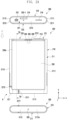
- the electronic device may include a first housing and a second housing which are coupled to each other so as to be movable with respect to each other.
- the first housing and the second housing of the electronic device may be at least partially fittedly coupled to each other so as to be slidable with respect to each other, and may support at least a part of the flexible display.
- the second housing may be introduced inside the first housing or ejected to the outside of the first housing.
- the second housing When the second housing is introduced in the first housing (in a slide-in state), a display region of the flexible display is reduced. When the second housing is ejected out of the first housing (in a slide-out state), the display region of the flexible display may be expanded.
- the flexible display may be disposed in the first housing so as to be partially bendable.
- the electronic device when the flexible display is expanded from a slide-in state to a slide-out state or reduced from a slide-out state to a slide-in state, the electronic device may perform a misoperation or may be damaged.
- a misoperation for example, in a particular situation such as the electronic device making a call, using a designated application (e.g., navigation application), being charged, or having been flipped over, the flexible display may be expanded or reduced even if a user doesn't want it to be.
- Various embodiments of the disclosure may provide a method and an electronic device by which shape transformation of a flexible display is controllable when the electronic device is in a designated state or situation.
- An electronic device includes a first housing, a second housing slidably coupled to the first housing, a flexible display having a visually exposed display region that is reduced or expanded based on sliding in or sliding out of the second housing, an input unit configured to receive an input, a processor, and memory storing instructions that, when executed by the processor, cause the electronic device to: identify whether a condition of the electronic device for disabling sliding in or sliding out of the second housing is satisfied, receive an input via the input unit, operate in a first mode in which slide-in or slide-out of the second housing is controlled based on the input and the condition not being satisfied, operate in the first mode in which slide-in or slide-out of the second housingis disabled based on the condition being satisfied, and operate in a second mode in which the slide-in or slide-out of the second housing is disabled regardless of the condition being satisfied or not.
- the method of controlling the electronic device is performed using a non-transitory computer-readable storage medium that stores one or more programs.
- the one or more programs include instructions for performing identifying whether a trigger signal for reducing or expanding a flexible display to correspond to sliding in or sliding out of a second housing slidably coupled to a first housing of the electronic device is input via an input unit, and providing a trigger selection mode for controlling sliding in or sliding out of the second housing, based on identification of input of the trigger signal.
- a user when an electronic device is in a designated state or situation, a user is able to selectively control at least one of a slide-in state, a slide-out state, and a fixed state of a flexible display (or rollable display) included in the electronic device, thereby reducing malfunction of or damage to the electronic device.
- FIG. 1 is a block diagram illustrating an electronic device 101 in a network environment 100 according to various embodiments.
- the electronic device 101 in the network environment 100 may communicate with an electronic device 102 via a first network 198 (e.g., a short-range wireless communication network), or at least one of an electronic device 104 or a server 108 via a second network 199 (e.g., a long-range wireless communication network).
- a first network 198 e.g., a short-range wireless communication network
- a second network 199 e.g., a long-range wireless communication network
- the electronic device 101 may communicate with the electronic device 104 via the server 108.
- the electronic device 101 may include a processor 120, memory 130, an input module 150, a sound output module 155, a display module 160, an audio module 170, a sensor module 176, an interface 177, a connecting terminal 178, a haptic module 179, a camera module 180, a power management module 188, a battery 189, a communication module 190, a subscriber identification module (SIM) 196, or an antenna module 197.
- at least one of the components e.g., the connecting terminal 178) may be omitted from the electronic device 101, or one or more other components may be added in the electronic device 101.
- some of the components e.g., the sensor module 176, the camera module 180, or the antenna module 197) may be implemented as a single component (e.g., the display module 160).
- the processor 120 may include a main processor 121 (e.g., a central processing unit (CPU) or an application processor (AP)), or an auxiliary processor 123 (e.g., a graphics processing unit (GPU), a neural processing unit (NPU), an image signal processor (ISP), a sensor hub processor, or a communication processor (CP)) that is operable independently from, or in conjunction with, the main processor 121.
- a main processor 121 e.g., a central processing unit (CPU) or an application processor (AP)
- auxiliary processor 123 e.g., a graphics processing unit (GPU), a neural processing unit (NPU), an image signal processor (ISP), a sensor hub processor, or a communication processor (CP)
- the main processor 121 may be adapted to consume less power than the main processor 121, or to be specific to a specified function.
- the auxiliary processor 123 may be implemented as separate from, or as part of the main processor 121.
- module may include a unit implemented in hardware, software, or firmware, and may interchangeably be used with other terms, for example, “logic,” “logic block,” “part,” or “circuitry”.
- a module may be a single integral component, or a minimum unit or part thereof, adapted to perform one or more functions.
- the module may be implemented in a form of an application-specific integrated circuit (ASIC).
- ASIC application-specific integrated circuit
- each component e.g., a module or a program of the above-described components may include a single entity or multiple entities, and some of the multiple entities may be separately disposed in different components. According to various embodiments, one or more of the above-described components may be omitted, or one or more other components may be added. Alternatively or additionally, a plurality of components (e.g., modules or programs) may be integrated into a single component. In such a case, according to various embodiments, the integrated component may still perform one or more functions of each of the plurality of components in the same or similar manner as they are performed by a corresponding one of the plurality of components before the integration.
- the second part 230b of the flexible display 230 may be disposed to be bent and accommodated in the first space 2101 of the first housing 210 and not to be seen from the outside in a state where the second housing 220 has been slid in along the second direction (direction (2)). Therefore, the flexible display 230 may have a display area that is changed according to the second housing 220 being slid from the first housing 210 in a designated direction (e.g., ⁇ y-axis direction). In the slide-out state, the second part 230b of the flexible display 230 may occupy the area, which is occupied by the first part 203a of the flexible display 230 in the slide-in state.
- the flexible display 230 may, in a slide-out state, be expanded to have a second display area (e.g., a region including the first part 230a and the second part 230b) which corresponds to a third length L3 greater than the first length L1 and is greater than the first display area according to sliding of the second housing 220 additionally moved by a second length L2 with respect to the first housing 210.
- a second display area e.g., a region including the first part 230a and the second part 230b
- the visible display area is increased due to the sliding-out of the second housing 220.
- the first camera module 205 among the camera modules and some sensor modules 204 among the sensor modules 204 and 217 may be arranged to detect an external environment through the flexible display 230.
- the first camera module 205 and some sensor modules 204 may be arranged to come into contact with an external environment through a perforated opening or a transmission region disposed on the flexible display 230 in the second space 2201 of the second housing 220.
- a region facing the first camera module 205 of the flexible display 230 is a part of an activation region displaying contents, and may be configured as a transmission region having a designated transmissivity.
- the transmission region may be configured to have a transmissivity within a range of about 5% to 20%.
- Such a transmission region may include a region overlapping with a valid region (e.g., an angle-of-view region) of the first camera module 205, through which light arriving at an image sensor to generate an image passes.
- the transmission region of the flexible display 230 may include a region having a pixel arrangement density and/or a wire density lower than the surrounding region.
- the transmission region may be replaced with the above opening.
- some camera modules 205 may include an under display camera (UDC).
- UDC under display camera
- some sensor modules 204 may be disposed to perform a function thereof without being visually exposed through the flexible display 230 in the second space 2201 of the second housing 220.
- the drive motor 260 including the pinion gear 260 may be disposed in the second space 2201 of the second housing 220, and the rack gear 2221 coupled to the pinion gear 261 may be disposed in the first space 2101 of the first housing 210.
- a processor e.g., the processor 120 in FIG. 1
- the electronic device 200 may operate the drive motor (e.g., the drive motor 260 in FIG. 4 ) disposed in the electronic device 200.
- the electronic device 200 may include the first housing 210 including the first space 2101, the second housing 220 coupled to the first housing 210 so as to be slidable therefrom and including the second space 2201, the support member 240 fixed to at least a part of the second housing 220 and at least partially bendably accommodated in the first space 2101 according to a slide-in operation, the flexible display 230 disposed to be supported by the second housing 220 and at least a part of the support member 240, and a drive module (e.g., a drive mechanism) that drives the second housing 220 from the first housing 210 in a slide-in direction (e.g., -y-axis direction) and/or a slide-out direction (e.g., y-axis direction).
- a drive module e.g., a drive mechanism
- the drive module may further include a speed reduction module (e.g., a speed reduction gear assembly) disposed to be coupled to the drive motor 260 to reduce a rotation speed and increase a driving force.
- the drive motor 260 may be disposed to be supported by a motor bracket 260a disposed on a support bracket 225 disposed in the first space 2101 of the first housing 210.
- the drive motor 260 may be fixed to, in the first space 2101, an end part (e.g., edge) of the support bracket 225 in a slide-out direction (e.g., y-axis direction).
- the rack gear 2221 may be fixed to and disposed on the second expansion part 222 of the second housing 220.
- the rack gear 2221 may be injection-molded on a part of the second expansion member 222, thereby being integrated therewith.
- the rack gear 2221 may be disposed to have a length in a direction parallel to a sliding direction (e.g., ⁇ y-axis direction). Therefore, when the electronic device 200 is assembled, the pinion gear 261 may be maintained to be gear-coupled to the rack gear 2221, and when a driving force of the drive motor 260 is provided to the pinion gear 261, the pinion gear is moved while riding on the rack gear 2221, whereby the second housing 220 may be moved with respect to the first housing 210. In an embodiment, a sliding distance of the second housing 220 may be determined by the length of the rack gear 2221.
- the electronic device 200 may include multiple electronic components arranged in the second space 2201.
- the multiple electronic components may include a first substrate 251 (e.g., main substrate), and the camera module 216, the speaker 207, the connector port 208, and the microphone 203-1 which are arranged around the first substrate 251.
- the multiple electronic components may be arranged around the first substrate 251 in the second space 2201 of the second housing 220, and thus may be efficiently electrically connectable.
- at least one of the above multiple electronic components may be disposed in the first space 2101 of the first housing 210.
- the electronic device 200 may include a rear bracket 224 disposed between the second expansion member 222 and the second rear cover 223 in the second housing 220.
- the rear bracket 224 may be disposed to cover at least a part of the multiple electronic components.
- the rear bracket 224 may be structurally coupled to at least a part of the second expansion member 222.
- the rear bracket 224 may be omitted.
- the rear bracket 224 may be disposed to cover the multiple electronic components and support the second rear cover 223.
- the at least one antenna element 224b may include a laser direct structuring (LDS) antenna pattern disposed on the outer surface of the rear bracket 224.
- the at least one antenna element 224b may include a conductive plate attached to the outer surface of the rear bracket 224, or a conductive paint or a conductive pattern disposed on the outer surface.
- the at least one antenna element 224b may be mounted in the rear bracket 224 when the rear bracket is injection-molded.
- the at least one antenna element 224b may be electrically connected to a wireless communication circuit (e.g., the wireless communication module 192 in FIG.
- the antenna member 253 may include a multi-function coil (or a multi-function core, MFC) for performing a wireless charging function, a near field communication (NFC) function, and/or an electronic payment function.
- the antenna member 253 may be electrically connected to the second substrate 252, thereby being electrically connected to the first substrate 251 through the second substrate 252.
- the second substrate 252 and/or the antenna member 253 may be electrically connected to the first substrate 251 through at least a part of the flexible substrate F1 connecting the drive motor 260 and the first substrate 251.
- the guide protrusions 2411 may be moved along the guide slits 2611, thereby assisting in reducing escaping or transformation of the flexible display 230 being operated.
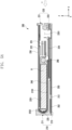
- FIG. 5A is a sectional view of an electronic device taken along vertical line 5a-5a in FIG. 2A according to various embodiments of the disclosure.
- FIG. 5B is a sectional view of an electronic device in an intermediate state according to various embodiments of the disclosure.
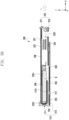
- FIG. 5C is a sectional view of an electronic device taken along vertical line 5c-5c in FIG. 3A according to various embodiments of the disclosure.
- the drive motor 260 may automatically move the second housing 220 with respect to the first housing 210 in a slide-in direction (direction (2)) or a slide-out direction (direction CD) through gear coupling between the pinion gear (e.g., the pinion gear 261 in FIG. 4 ) and the rack gear 2221 (e.g., the rack gear 2221 in FIG. 4 ).
- the electronic device 200 may control driving of the drive motor 260, thereby transitioning from an intermediate state (a state of FIG. 5B ) to a slide-out state (a state of FIG. 5C ).
- the electronic device 200 may be configured to stop in a designated intermediate state between a slide-in state and a slide-out state (a free-stop function).
- the visible area of the flexible display 230 may be gradually adjusted.
- the electronic device 200 may transition to a slide-in state, an intermediate state, or a slide-out state through a user's manipulation while a driving force is not provided to the drive motor 260.
- the visible area of the flexible display 230 may be adjusted manually.
- the electronic device 200 may include a battery B disposed in the battery seating part 2251 of the support bracket 225 fixed to the first space 2101 of the first housing 210.
- the battery B is disposed in the first housing 210 and may not require a separate drive gap for avoiding interference with surrounding structures according to movement. Therefore, the thickness of the battery B may be expanded in a manner of becoming close to or coming into contact with a back surface of the support member 240 from the battery seating part 2251 of the support bracket 225, whereby the battery has a relatively increased volume and supports the moving support member 240, so that sagging of the flexible display 230 may be reduced and operational reliability may be improved.
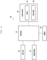
- FIG. 6 is a block diagram roughly illustrating a configuration of an electronic device including a flexible display according to an embodiment of the disclosure.
- the electronic device 200 disclosed below may include embodiments described for the electronic device 101 in FIG. 1 and/or the electronic device 200 in FIG. 2A to FIG. 5C .
- embodiment related to the electronic device 200 disclosed below may be integrated with or applied to embodiments described for the electronic device 101 in FIG. 1 and/or the electronic device 200 in FIG. 2A to FIG. 5C .
- the same reference numerals may be assigned to elements substantially the same as those in the embodiments described with reference to FIG. 1 to FIG. 5C , and overlapped description may be omitted.
- a configuration of the electronic device 200 described with reference to FIG. 6 may be substantially identically applied to the embodiments of the electronic device 200 described below.
- a rollable type electronic device or a sliding type electronic device are described as an example.
- the disclosure is not limited thereto, and the embodiments may be substantially identically applied to various electronic devices including the flexible display 230 (e.g., a flexible display or an expandable display).
- the second housing 220 of the electronic device 200 is slid in a vertical direction (e.g., y-axis direction) with respect to the first housing 210 is described.
- the disclosure is not limited thereto, and the embodiment may be substantially identically applied to embodiments in which the first housing 210 and the second housing 220 are slid in a horizontal direction (e.g., x-axis direction and/or -x-axis direction).
- a horizontal direction e.g., x-axis direction and/or -x-axis direction.
- the sensor module 176, the memory 130, and/or the processor 120 may be arranged on at least one of the first substrate 251 and the second substrate 252 described with reference to FIG. 4 .
- the input unit 610, the flexible display 230, the sensor module 176, the memory 130, and/or the processor 120 may be operatively connected to each other.
- the flexible display 230 may transfer information input by a user of the electronic device 200 to the processor 120.
- the flexible display 230 may detect at least one of a selection or touch signal, a long press signal, a double tap signal, a drag and drop signal, a swipe signal, and a tap signal which are input through a user of the electronic device 200.
- the flexible display 230 may transfer, to the processor 120, the selection or touch signal, the long press signal, the double tap signal, the drag and drop signal, the swipe signal, or the tap signal which has been detected.
- the processor 120 may control a slide-in state, a slide-out state, and/or a fixed state of the flexible display 230, based on a signal transferred via the flexible display 230.
- the flexible display 230 may provide and display a notification (e.g., a pop-up) notifying of the state or situation of the electronic device 200.
- the first display region (e.g., the first part 230a in FIG. 3A ) and the second display region (e.g., the second part 230b in FIG. 3A ) of the flexible display 230 may be exposed to a user of the electronic device 200.
- the first display region 230a of the flexible display 230 may be exposed to the outside of the electronic device 200 and the second display region 230b may not be exposed to the outside of the electronic device 200.
- the flexible display 230 may perform a display function and an input function.
- the flexible display 230 may include a display 621 and a touch panel 623 to perform the display function and the input function.
- the display 621 may visually provide a menu of the electronic device 200, input data, function configuration information, and various pieces of information (e.g., user interface, icon, and/or application) to a user.
- the display 621 may include at least one of a liquid crystal display (LCD), organic light emitting diodes (OLED), and active matrix organic light emitting diodes (AMOLED).
- the touch panel 623 may include a pressure sensor or a touch sensor including capacitive overlay, resistive overlay, or infrared beam.
- the touch panel 623 may include various types of sensing means capable of contact or pressure by an object (finger or stylus pen) other than the sensors.
- the touch panel 623 may detect a selection or a touch (e.g., a finger or a stylus pen) of a user of the electronic device 200, and transfer a detected signal to the processor 120.
- the detected signal may include at least one of coordinate information, direction information, or touch angle information related to a touch input of a user of the electronic device 200.
- the sensor module 176 is not limited to the above sensors, and may also include a proximity sensor, a time-of-flight (TOF) sensor, an ultrasonic sensor, a fingerprint recognition sensor, a gesture sensor, an atmospheric pressure sensor, a magnetic sensor, a grip sensor, a color sensor, an infrared (IR) sensor, and/or a biometric sensor.
- a proximity sensor e.g., a proximity sensor, a time-of-flight (TOF) sensor, an ultrasonic sensor, a fingerprint recognition sensor, a gesture sensor, an atmospheric pressure sensor, a magnetic sensor, a grip sensor, a color sensor, an infrared (IR) sensor, and/or a biometric sensor.
- TOF time-of-flight
- IR infrared
- the processor 120 may identify that a case where the electronic device 200 having been flipped over toward the ground is a designated state (e.g., a state corresponding to a designated condition), by using the sensor module 176 (e.g., a geomagnetic sensor, an acceleration sensor, a direction sensor, an angular velocity sensor, and/or a gyro sensor).
- a designated state e.g., a state corresponding to a designated condition
- the sensor module 176 e.g., a geomagnetic sensor, an acceleration sensor, a direction sensor, an angular velocity sensor, and/or a gyro sensor.
- the sensor module 176 may detect whether the internal temperature of the electronic device 200 exceeds a designated temperature.
- the processor 120 may detect a temperature caused by overload of a drive motor (e.g., the drive motor 260 in FIG. 4 ) of the electronic device 200 by using the temperature sensor, and control the electronic device 200 being switched from a slide-in state to a slide-out state or switched from a slide-out state to a slide-in state, so as to reduce damage to the drive motor 260.
- a drive motor e.g., the drive motor 260 in FIG. 4
- the processor 120 may identify that a case where moisture being detected from the connector port 208 of the electronic device 200 is a designated state (e.g., a state corresponding to a designated condition), by using the sensor module 176 (e.g., a humidity sensor).
- a designated state e.g., a state corresponding to a designated condition
- the processor 120 may identify that a case where the electronic device 200 being in a designated place (e.g., a closed place) is a designated state (e.g., a state corresponding to a designated condition), by using the sensor module 176 (e.g., illuminance sensor and/or the geomagnetic sensor).
- a designated place e.g., a closed place
- the sensor module 176 e.g., illuminance sensor and/or the geomagnetic sensor
- the designated state or the state corresponding to the designated condition may include a case where the electronic device 200 is making a call or is running a designated application, a case where the flexible display 230 has been flipped over toward the ground, a case where the internal temperature of the electronic device 200 exceeds the designated temperature, a case where moisture is detected from the connector port 208 of the electronic device 200, a case where the electronic device 200 is in a designated place, and/or a case where the electronic device 200 is being charged.
- Such information can be used to provide a protection in case of the electronic device being dropped or to prevent ingress of moisture.
- the designated state or the state corresponding to the designated condition may be identified based on state identification information of the second housing 220 relative to the first housing 210.
- the memory 130 may store a configuration value related to a touch sensitivity, a touch region, a touch pressure, and/or a touch time for at least one of a selection or touch signal, a long press signal, a double tap signal, a drag and drop signal, a swipe signal, and a tap signal which are input via the input unit 610 and the flexible display 230.
- the memory 130 may store at least one user interface related to an initial screen and/or a configuration screen of the electronic device 200.
- the memory 130 may perform a function of storing a program (e.g., the program 140 in FIG. 1 ) for processing and controlling the processor 120, an operating system (e.g., the operating system 142 in FIG. 1 ), various applications, and input/output data.
- the memory 130 may store a program for controlling overall operations of the electronic device 200.
- the memory 130 may store various configuration information required for processing a function in the electronic device 200.
- the memory 130 may store at least one executable instruction.
- the electronic device 200 may identify whether a condition of the electronic device 200 for disabling sliding in or sliding out of the second housing 220 is satisfied.
- the electronic device 200 may receive an input via the input unit 610(e.g., trigger signal input unit).
- the electronic device 200 may operate in a first mode in which slide-in or slide-out of the second housing 220 is controlled based on the input and the condition not being satisfied.
- the electronic device 200 may operate in the first mode in which slide-in or slide-out of the second housing 220 is disabled based on the condition being satisfied.
- the electronic device 200 may operate in a second mode in which the slide-in or slide-out of the second housing 220 is disabled regardless of the condition being satisfied or not.
- the condition of the electronic device (200) for deactivating sliding in or sliding out of the second housing (220) is identified as being satisfied if the flexible display (230) of the electronic device (200) facing down. According to an embodiment, the condition of the electronic device (200) for deactivating sliding in or sliding out of the second housing (220) is identified as being satisfied if the electronic device (200) is placed in a pocket. According to an embodiment, the condition of the electronic device (200) for deactivating sliding in or sliding out of the second housing (220) is identified as being satisfied if a defined application is being executed. According to an embodiment, the condition of the electronic device (200) for deactivating sliding in or sliding out of the second housing (220) is identified as being satisfied if the electronic device (200) is being charged.
- the trigger selection mode may include a fixing mode (e.g., a second mode) of not changing, by the processor 120, a slide-in or slide-out state of the second housing 220 when a trigger signal for driving the second housing 220 to be slid in or slid out is input.
- the trigger selection mode may include a display reduction or expansion mode (e.g., a third mode) of changing, by the processor 120, a slide-in or slide-out state of the second housing 220 to correspond to input of the trigger signal for driving the second housing 220 to be slid in or slid out.
- the trigger selection mode may include a smart mode (e.g., a first mode) of, when the trigger signal for driving the second housing 220 to be slid in or slid out is input, identifying, by the processor 120, the state of the second housing 220, and changing, by the processor 120, a slide-in or slide-out state of the second housing 220, based on state identification information of the second housing 220.
- a smart mode e.g., a first mode
- the processor 120 may identify the state (e.g., a state corresponding to a designated state or a designated condition) of the second housing 220 when a trigger signal for driving the second housing 220 to be slid in or slid out is input.
- the processor 120 may change a slide-in or slide-out state of the second housing 220, based on state identification information of the second housing 220.
- the state identification information of the second housing 220 may include information of identifying whether the second housing 220 is in a state corresponding to the designated state or designated condition with respect to the first housing 210.
- the processor 120 may, in the smart mode, when the flexible display 230 is identified as having been flipped over toward the ground or being in a pocket, based on the state identification information of the second housing 220, control not to change a slide-in or slide-out state of the second housing 220.
- the processor 120 may, in the smart mode, when the electronic device 200 is running a designated application or the electronic device 200 is being charged, control not to change a slide-in or slide-out state of the second housing 220.
- the electronic device 200 being charged may include the case that a wireless charging operation is performed. Such information can be used to prevent charge churn, for example.
- the processor 120 may, in the smart mode, detect the internal temperature and/or moisture of the electronic device 200 by using the sensor module 176 and, when the internal temperature of the electronic device 200 exceeds a designated temperature or moisture is detected in the electronic device 200, control not to change a slide-in or slide-out state of the second housing 220. Such information can be used to prevent breakage of the drive motor 260 and/or moisture ingress.
- the processor 120 may control the second housing 220 not to change a slide-in or slide-out state.
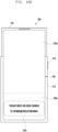
- the processor 120 may be configured to, in the fixing mode (e.g., second mode), when the trigger signal is input via the input unit 610, allow the flexible display 230 to provide a pop-up message 1720 notifying that the fixing mode has been configured.
- the fixing mode e.g., second mode
- the second mode may include a fixing mode of restricting the electronic device 200 not to be switched to a slide-in state (e.g., a reduction mode) and/or a slide-out state (e.g., an expansion mode)
- a fixing mode of restricting the electronic device 200 not to be switched to a slide-in state e.g., a reduction mode
- a slide-out state e.g., an expansion mode
- a user of the electronic device 200 may input a trigger signal by, for example, performing a tap 1710 on the input unit 610 (e.g., the key input device 219 mentioned with reference to FIG. 2A to FIG. 3B ) disposed on one lateral surface of the first housing 210.
- the input unit 610 e.g., the key input device 219 mentioned with reference to FIG. 2A to FIG. 3B
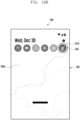
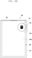
- the electronic device 200 when a user of the electronic device 200 touches the first mode change icon 710 displayed on the flexible display 230, the electronic device 200 may be configured to be in the first mode (e.g., a reduction mode and/or expansion mode).
- the flexible display 230 may be switched from a slide-in state to a slide-out state as illustrated in FIG. 18D .
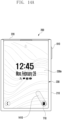
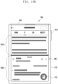
- a screen of the first window 1910 may be displayed on a first display region (e.g., the first part 230a in FIG. 3A ) of the flexible display 230
- a screen of the second window 1920 may be displayed on a second display region (e.g., the second part 230b in FIG. 3A ).
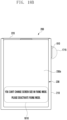
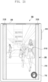
- FIG. 21 is a diagram roughly illustrating a screen in which a flexible display of an electronic device according to an embodiment of the disclosure displays image information.
- the electronic device when a user of the electronic device 200 touches the first mode change icon 710 displayed on the flexible display 230, the electronic device may be configured to be in the first mode (e.g., a reduction mode and/or expansion mode).
- the flexible display 230 may be switched from a slide-in state to a slide-out state as illustrated in FIG. 18D .
- the image information 2110 may be expanded and displayed through the first display region (e.g., the first part 230a in FIG. 3A ) and the second display region (e.g., the second part 230b in FIG. 3A ) of the flexible display 230 so as to remove the letter box 2120.
- the processor 120 may identify, based on the above monitoring, that a case where the electronic device 200 is making a call or is running a designated application, a case where the flexible display 230 has been flipped over toward the ground, a case where the internal temperature of the electronic device 200 exceeds the designated temperature, a case where moisture is detected from the connector port 208 of the electronic device 200, a case where the electronic device 200 is in a designated place, and/or a case where the electronic device 200 is being charged is the designated state or the state corresponding to the designated condition.
- the processor 120 may restrict the flexible display 230 being switched from a slide-in state to a slide-out state or switched from a slide-out state to a slide-in state.
- a method mentioned with reference to FIG. 23 may be performed, for example, by means of the elements of the electronic device 200 described with reference to FIG. 6 .
- the method mentioned with reference to FIG. 23 may include, for example, embodiments described with reference to FIG. 1 to FIG. 22 .
- operations may be sequentially performed, but sequential performance is not necessarily required. For example, the order of the operations may be changed. For example, the operations may be performed in parallel. For example, the operations may not be performed all and at least some of them may be performed.
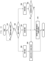
- the processor 120 may identify whether a trigger signal for switching the electronic device 200 from a slide-in state to a slide-out state or switching same from a slide-out state to a slide-in state is input via the input unit 610.
- the processor 120 may identify which mode the electronic device 200 has been configured to be in.
- the processor 120 may identify whether the electronic device 200 has been configured to be in a first mode (e.g., a reduction mode and/or expansion mode), a second mode (e.g., a fixing mode), or a third mode (e.g., a smart mode), through operation 2320 above.
- a first mode e.g., a reduction mode and/or expansion mode
- a second mode e.g., a fixing mode
- a third mode e.g., a smart mode
- the processor 120 may control the state of the flexible display 230 to be switched, based on the trigger signal in operation 2360.
- the processor 120 may control the flexible display 230 to be switched from a slide-in state to a slide-out state or switched from a slide-out state to a slide-in state.
- the processor 120 may perform control to restrict the state of the flexible display 230 being switched in operation 2370.
- the processor 120 may restrict the flexible display 230 being switched from a slide-in state to a slide-out state or switched from a slide-out state to a slide-in state.
- the processor 120 may perform control to restrict the state of the flexible display 230 being switched, as in operation 2370.
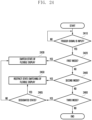
- FIG. 24 is a flowchart roughly illustrating a method of controlling mode change of an electronic device according to various embodiments of the disclosure.
- the processor 120 may identify whether a trigger signal for switching the electronic device 200 from a slide-in state to a slide-out state or switching same from a slide-out state to a slide-in state is input via the input unit 610.
- the processor 120 may control the state of the flexible display 230 to be switched, based on the trigger signal.
- the processor 120 may control the flexible display 230 to be switched from a slide-in state to a slide-out state or switched from a slide-out state to a slide-in state.
- the processor 120 may perform control to restrict the state of the flexible display 230 being switched.
- the processor 120 may restrict the flexible display 230 being switched from a slide-in state to a slide-out state or switched from a slide-out state to a slide-in state.
- the processor 120 may identify whether the electronic device 200 has been configured to be in a third mode (e.g., a smart mode).
- a third mode e.g., a smart mode
- the processor 120 may identify whether the electronic device 200 is in a state corresponding to a designated condition.
- the processor 120 may control the state of the flexible display 230 to be switched, based on a trigger signal as in operation 2430.
- the processor 120 may perform control to restrict the state of the flexible display 230 being switched, as in operation 2450.
- An electronic device 200 may include a first housing 210, a second housing 220 slidably coupled to the first housing 210, a flexible display 230 having a visually exposed display region (230a, 230b) that is reduced or expanded based on sliding in or sliding out of the second housing 220, an input unit 610 configured to receive an input, a processor 120, and, memory 130 storing instructions that, when executed by the processor, cause the electronic device to: identify whether a condition of the electronic device for disabling sliding in or sliding out of the second housing is satisfied, receive an input via the input unit, operate in a first mode in which slide-in or slide-out of the second housing 220 is controlled based on the input and the condition not being satisfied, operate in the first mode in which slide-in or slide-out of the second housing 220 is disabled based on the condition being satisfied, and operate in a second mode in which the slide-in or slide-out of the second housing 220 is disabled regardless of the condition being satisfied or not.
- the electronic device 200 is configured to provide a trigger selection mode for controlling sliding in or sliding out of the second housing 220, based on the input.
- condition of the electronic device 200 for deactivating sliding in or sliding out of the second housing 220 is identified as being satisfied if the flexible display 230 of the electronic device 200 facing down.
- condition of the electronic device 200 for deactivating sliding in or sliding out of the second housing 220 is identified as being satisfied if the electronic device 200 is placed in a pocket.
- condition of the electronic device 200 for deactivating sliding in or sliding out of the second housing 220 is identified as being satisfied if a defined application is being executed.
- the electronic device 200 may further include a sensor module 176, and in the first mode, the processor 120 may detect an internal temperature and/or moisture of the electronic device 200 by using the sensor module 176 and, in case that the internal temperature of the electronic device 200 exceeds a designated temperature or moisture is detected in the electronic device 200, may control not to change the slide-in or slide-out state of the second housing 220. This may prevent breakage of the drive motor 260 and/or moisture ingress.
- the method may include controlling not to change the slide-in or slide-out state of the second housing 220 in case that the electronic device 200 is running a designated application or the electronic device 200 is being charged.
- the method may include controlling a state change of the flexible display 230, based on at least one of a touch signal, a long press signal, a double tap signal, a drag and drop signal, a swipe signal, and a tap signal which are input via the input unit 610.
Landscapes
- Engineering & Computer Science (AREA)
- Theoretical Computer Science (AREA)
- Human Computer Interaction (AREA)
- Physics & Mathematics (AREA)
- General Engineering & Computer Science (AREA)
- General Physics & Mathematics (AREA)
- Computer Hardware Design (AREA)
- Signal Processing (AREA)
- Mathematical Physics (AREA)
- Computer Networks & Wireless Communication (AREA)
- Environmental & Geological Engineering (AREA)
- User Interface Of Digital Computer (AREA)
Applications Claiming Priority (3)
| Application Number | Priority Date | Filing Date | Title |
|---|---|---|---|
| KR20220147258 | 2022-11-07 | ||
| KR1020220185208A KR20240066033A (ko) | 2022-11-07 | 2022-12-27 | 롤러블 디스플레이를 포함하는 전자 장치 및 상기 전자 장치의 제어 방법 |
| PCT/KR2023/017498 WO2024101789A1 (ko) | 2022-11-07 | 2023-11-03 | 플렉서블 디스플레이를 포함하는 전자 장치 및 상기 전자 장치의 제어 방법 |
Publications (2)
| Publication Number | Publication Date |
|---|---|
| EP4395291A1 true EP4395291A1 (de) | 2024-07-03 |
| EP4395291A4 EP4395291A4 (de) | 2025-05-21 |
Family
ID=91032898
Family Applications (1)
| Application Number | Title | Priority Date | Filing Date |
|---|---|---|---|
| EP23814078.4A Pending EP4395291A4 (de) | 2022-11-07 | 2023-11-03 | Elektronische vorrichtung mit flexibler anzeige und steuerungsverfahren für elektronische vorrichtung |
Country Status (4)
| Country | Link |
|---|---|
| US (1) | US20250181295A1 (de) |
| EP (1) | EP4395291A4 (de) |
| CN (1) | CN119817090A (de) |
| WO (1) | WO2024101789A1 (de) |
Family Cites Families (9)
| Publication number | Priority date | Publication date | Assignee | Title |
|---|---|---|---|---|
| KR101562582B1 (ko) * | 2008-12-30 | 2015-10-22 | 엘지전자 주식회사 | 플렉시블 디스플레이를 적용한 이동 단말기 및 그의 화면확장방법 |
| US9916031B2 (en) * | 2013-12-26 | 2018-03-13 | Intel Corporation | Mechanism to avoid unintentional user interaction with a convertible mobile device during conversion |
| US12443233B2 (en) * | 2019-09-06 | 2025-10-14 | Lg Electronics Inc. | Mobile terminal and method for controlling the same |
| KR102861429B1 (ko) * | 2019-11-14 | 2025-09-18 | 엘지전자 주식회사 | 이동 단말기 및 그 제어 방법 |
| WO2021160276A1 (en) * | 2020-02-14 | 2021-08-19 | Huawei Technologies Co., Ltd. | Rolling gesture and mistouch prevention on rolling devices |
| WO2021221184A1 (ko) * | 2020-04-27 | 2021-11-04 | 엘지전자 주식회사 | 이동단말기 및 그 제어방법 |
| WO2022098145A1 (ko) * | 2020-11-06 | 2022-05-12 | 삼성전자 주식회사 | 플렉서블 디스플레이를 포함하는 전자 장치 및 방법 |
| EP4191383A4 (de) * | 2020-11-06 | 2024-01-03 | Samsung Electronics Co., Ltd. | Elektronische vorrichtung mit flexibler anzeige und betriebsverfahren dafür |
| EP4213004A4 (de) * | 2020-12-04 | 2024-03-13 | Samsung Electronics Co., Ltd. | Elektronische vorrichtung mit flexibler anzeige und verfahren zum betrieb einer elektronischen vorrichtung |
-
2023
- 2023-11-03 WO PCT/KR2023/017498 patent/WO2024101789A1/ko not_active Ceased
- 2023-11-03 EP EP23814078.4A patent/EP4395291A4/de active Pending
- 2023-11-03 CN CN202380060872.4A patent/CN119817090A/zh active Pending
-
2025
- 2025-01-28 US US19/039,212 patent/US20250181295A1/en active Pending
Also Published As
| Publication number | Publication date |
|---|---|
| US20250181295A1 (en) | 2025-06-05 |
| WO2024101789A1 (ko) | 2024-05-16 |
| CN119817090A (zh) | 2025-04-11 |
| EP4395291A4 (de) | 2025-05-21 |
Similar Documents
| Publication | Publication Date | Title |
|---|---|---|
| EP4175267B1 (de) | Elektronische vorrichtung zur bereitstellung eines gemeinsamen bildschirms und eines privaten bildschirms und steuerungsverfahren dafür | |
| US12284301B2 (en) | Slidable electronic device and operating method thereof | |
| EP4261674A1 (de) | Elektronische vorrichtung und verfahren zur konfiguration des layouts auf basis des faltzustands einer elektronischen vorrichtung | |
| US20230333605A1 (en) | Electronic device providing status information by changing shape of electronic device, and method for controlling the same | |
| US12333974B2 (en) | Electronic device including expandable display and content provision method | |
| EP4216046A1 (de) | Elektronische vorrichtung mit anzeige mit variablem anzeigebereich und verfahren zum variablen betrieb eines aspektverhältnisses unter verwendung eines app-symbols | |
| US20230289047A1 (en) | Electronic device, and electronic device operation method | |
| US20240431049A1 (en) | Slidable electronic device considering component placement space | |
| EP4375820A1 (de) | Flexible elektronische vorrichtung und verfahren zur steuerung der anzeige eines anwendungsausführungsbildschirms | |
| US12431051B2 (en) | Electronic device having flexible display | |
| EP4242823A1 (de) | Elektronische vorrichtung mit flexibler anzeige und verfahren zum betrieb davon | |
| US20260081984A1 (en) | Electronic device comprising flexible display, and operating method thereof | |
| US12399528B2 (en) | Electronic device including flexible display and method for controlling input area for expansion and reduction of display in the electronic device | |
| US20250168269A1 (en) | Electronic device for reconstructing background image | |
| US12561044B2 (en) | Method and device for providing wallpaper in electronic device | |
| US12431050B2 (en) | Electronic device comprising expandable display, and user interface provision method | |
| US20250008011A1 (en) | Electronic apparatus including antenna | |
| US20240314236A1 (en) | Electronic device, and method by which electronic device displays display mode information on basis of context information | |
| EP4395291A1 (de) | Elektronische vorrichtung mit flexibler anzeige und steuerungsverfahren für elektronische vorrichtung | |
| US12236075B2 (en) | Electronic device including flexible display and operating method thereof | |
| EP4694102A1 (de) | Elektronische vorrichtung und motorantriebsverfahren damit | |
| US20250201159A1 (en) | Electronic device including flexible display and method for controlling same | |
| EP4550767A1 (de) | Mehrfenstersteuerungsverfahren einer elektronischen vorrichtung und elektronische vorrichtung | |
| US20250321671A1 (en) | Electronic device with changeable shape on basis of user's gesture on screen and control method thereof | |
| EP4580170A1 (de) | Elektronische vorrichtung mit verschiebbarer anzeige und verfahren zum betrieb davon |
Legal Events
| Date | Code | Title | Description |
|---|---|---|---|
| STAA | Information on the status of an ep patent application or granted ep patent |
Free format text: STATUS: UNKNOWN |
|
| STAA | Information on the status of an ep patent application or granted ep patent |
Free format text: STATUS: THE INTERNATIONAL PUBLICATION HAS BEEN MADE |
|
| PUAI | Public reference made under article 153(3) epc to a published international application that has entered the european phase |
Free format text: ORIGINAL CODE: 0009012 |
|
| STAA | Information on the status of an ep patent application or granted ep patent |
Free format text: STATUS: REQUEST FOR EXAMINATION WAS MADE |
|
| 17P | Request for examination filed |
Effective date: 20231207 |
|
| AK | Designated contracting states |
Kind code of ref document: A1 Designated state(s): AL AT BE BG CH CY CZ DE DK EE ES FI FR GB GR HR HU IE IS IT LI LT LU LV MC ME MK MT NL NO PL PT RO RS SE SI SK SM TR |
|
| REG | Reference to a national code |
Ref country code: DE Ref legal event code: R079 Free format text: PREVIOUS MAIN CLASS: H04M0001724540 Ipc: G06F0001160000 |
|
| A4 | Supplementary search report drawn up and despatched |
Effective date: 20250422 |
|
| RIC1 | Information provided on ipc code assigned before grant |
Ipc: H04M 1/02 20060101ALI20250414BHEP Ipc: H04M 1/72463 20210101ALI20250414BHEP Ipc: H04M 1/72469 20210101ALI20250414BHEP Ipc: H04M 1/72454 20210101ALI20250414BHEP Ipc: G06F 3/0482 20130101ALI20250414BHEP Ipc: G06F 3/04817 20220101ALI20250414BHEP Ipc: G06F 1/16 20060101AFI20250414BHEP |
|
| DAV | Request for validation of the european patent (deleted) | ||
| DAX | Request for extension of the european patent (deleted) |