EP4395192A1 - Wireless communication method, wireless communication system, and transmission device - Google Patents
Wireless communication method, wireless communication system, and transmission device Download PDFInfo
- Publication number
- EP4395192A1 EP4395192A1 EP21955101.7A EP21955101A EP4395192A1 EP 4395192 A1 EP4395192 A1 EP 4395192A1 EP 21955101 A EP21955101 A EP 21955101A EP 4395192 A1 EP4395192 A1 EP 4395192A1
- Authority
- EP
- European Patent Office
- Prior art keywords
- unit
- precoding
- tap length
- stream
- communication path
- Prior art date
- Legal status (The legal status is an assumption and is not a legal conclusion. Google has not performed a legal analysis and makes no representation as to the accuracy of the status listed.)
- Granted
Links
Images




Classifications
-
- H—ELECTRICITY
- H04—ELECTRIC COMMUNICATION TECHNIQUE
- H04B—TRANSMISSION
- H04B1/00—Details of transmission systems, not covered by a single one of groups H04B3/00 - H04B13/00; Details of transmission systems not characterised by the medium used for transmission
- H04B1/02—Transmitters
- H04B1/04—Circuits
- H04B1/0475—Circuits with means for limiting noise, interference or distortion
-
- H—ELECTRICITY
- H04—ELECTRIC COMMUNICATION TECHNIQUE
- H04L—TRANSMISSION OF DIGITAL INFORMATION, e.g. TELEGRAPHIC COMMUNICATION
- H04L25/00—Baseband systems
- H04L25/02—Details ; arrangements for supplying electrical power along data transmission lines
- H04L25/03—Shaping networks in transmitter or receiver, e.g. adaptive shaping networks
- H04L25/03006—Arrangements for removing intersymbol interference
- H04L25/03343—Arrangements at the transmitter end
-
- H—ELECTRICITY
- H04—ELECTRIC COMMUNICATION TECHNIQUE
- H04B—TRANSMISSION
- H04B7/00—Radio transmission systems, i.e. using radiation field
- H04B7/02—Diversity systems; Multi-antenna system, i.e. transmission or reception using multiple antennas
- H04B7/04—Diversity systems; Multi-antenna system, i.e. transmission or reception using multiple antennas using two or more spaced independent antennas
- H04B7/0413—MIMO systems
- H04B7/0456—Selection of precoding matrices or codebooks, e.g. using matrices antenna weighting
-
- H—ELECTRICITY
- H04—ELECTRIC COMMUNICATION TECHNIQUE
- H04B—TRANSMISSION
- H04B1/00—Details of transmission systems, not covered by a single one of groups H04B3/00 - H04B13/00; Details of transmission systems not characterised by the medium used for transmission
- H04B1/02—Transmitters
- H04B1/04—Circuits
- H04B2001/0408—Circuits with power amplifiers
- H04B2001/0425—Circuits with power amplifiers with linearisation using predistortion
-
- H—ELECTRICITY
- H04—ELECTRIC COMMUNICATION TECHNIQUE
- H04L—TRANSMISSION OF DIGITAL INFORMATION, e.g. TELEGRAPHIC COMMUNICATION
- H04L25/00—Baseband systems
- H04L25/02—Details ; arrangements for supplying electrical power along data transmission lines
- H04L25/03—Shaping networks in transmitter or receiver, e.g. adaptive shaping networks
- H04L25/03006—Arrangements for removing intersymbol interference
- H04L2025/03433—Arrangements for removing intersymbol interference characterised by equaliser structure
- H04L2025/03535—Variable structures
- H04L2025/03547—Switching between time domain structures
- H04L2025/03566—Switching between time domain structures between different tapped delay line structures
- H04L2025/03585—Modifying the length
-
- Y—GENERAL TAGGING OF NEW TECHNOLOGICAL DEVELOPMENTS; GENERAL TAGGING OF CROSS-SECTIONAL TECHNOLOGIES SPANNING OVER SEVERAL SECTIONS OF THE IPC; TECHNICAL SUBJECTS COVERED BY FORMER USPC CROSS-REFERENCE ART COLLECTIONS [XRACs] AND DIGESTS
- Y02—TECHNOLOGIES OR APPLICATIONS FOR MITIGATION OR ADAPTATION AGAINST CLIMATE CHANGE
- Y02D—CLIMATE CHANGE MITIGATION TECHNOLOGIES IN INFORMATION AND COMMUNICATION TECHNOLOGIES [ICT], I.E. INFORMATION AND COMMUNICATION TECHNOLOGIES AIMING AT THE REDUCTION OF THEIR OWN ENERGY USE
- Y02D30/00—Reducing energy consumption in communication networks
- Y02D30/70—Reducing energy consumption in communication networks in wireless communication networks
Definitions
- the present invention relates to a wireless communication method, a wireless communication system, and a transmission device.
- the peak power when a large peak power is generated, the peak power may be amplified in a non-linear region of an amplifier, and the communication quality may deteriorate due to non-linear distortion (refer to, for example, Non Patent Literature 1).
- a tap length in the precoding is a fixed value.
- Non Patent Literature 1 MOHAMED IBNKAHLA, et al., "High-Speed Satellite Mobile Communications: Technologies and Challenges", PROCEEDINGS OF THE IEEE, VOL. 92, NO. 2, FEBRUARY 2004, p.312-339
- Non Patent Literature 2 Keita Kuriyama, Hayato Fukuzono, Masafumi Yoshioka, Tsutomu Tatsuta, "FIR-type Transmit Beamforming for Wide-band Single Carrier MIMO Transmission", The Institute of Electronics, Information and Communication Engineers, IEICE Technical Report, Jan.2019, p.31-36
- a difference in magnitude occurs in an m-th tap coefficient depending on a channel state.
- the tap length in the precoding may be excessive with respect to the tap length necessary for obtaining desired bit error rate (BER) characteristics.
- BER bit error rate
- PAPR peak to average power ratio
- the tap length may be insufficient, and inter-stream interference and inter-symbol interference may increase.
- the present invention has been made in view of the above-described problems, and an object thereof is to provide a wireless communication method, a wireless communication system, and a transmission device capable of improving the quality of wireless communication even when a channel state varies.
- a wireless communication method of transmitting a signal from a transmission device to a reception device including a precoding step of precoding a stream of a transmission signal in a time domain by using an FIR filter; a transmission power control step of controlling a transmission power of the precoded stream; an amplification step of amplifying the precoded stream such that the controlled transmission power is obtained; and a tap length control step of performing control for changing a tap length in the precoding step such that the tap length is decreased in a case where a magnitude of a last tap coefficient in the precoding step is small and the tap length is increased in a case where the magnitude is large, with respect to a threshold value calculated on the basis of quality information of a received signal fed back from the reception device that has received the amplified stream or quality information of a received signal calculated by using at least characteristics of an amplification unit of the transmission device.
- a wireless communication system that transmits a signal from a transmission device to a reception device, including a precoding unit that precodes a stream of a transmission signal in a time domain by using an FIR filter; a transmission power control unit that controls a transmission power of the stream precoded by the precoding unit; an amplification unit that amplifies the stream precoded by the precoding unit under control of the transmission power control unit; and a tap length control unit that performs control for changing a tap length in the precoding unit such that the tap length is decreased in a case where a magnitude of a last tap coefficient in the precoding unit is small and the tap length is increased in a case where the magnitude is large, with respect to a threshold value calculated on the basis of quality information of a received signal fed back from the reception device that has received the stream by the amplification unit or quality information of a received signal calculated by using at least characteristics of the amplification unit.
- a transmission device including a precoding unit that precodes a stream of a transmission signal in a time domain by using an FIR filter; a transmission power control unit that controls a transmission power of the stream precoded by the precoding unit; an amplification unit that amplifies the stream precoded by the precoding unit under control of the transmission power control unit; and a tap length control unit that performs control for changing a tap length in the precoding unit such that the tap length is decreased in a case where a magnitude of a last tap coefficient in the precoding unit is small and the tap length is increased in a case where the magnitude is large, with respect to a threshold value calculated on the basis of quality information of a received signal fed back from the reception device that has received the stream amplified by the amplification unit or quality information of a received signal calculated by using at least characteristics of the amplification unit.
- Fig. 1 is a diagram illustrating a configuration example of a wireless communication system 1 according to the embodiment.
- the wireless communication system 1 is, for example, a multiple input multiple output (MIMO) system in which a transmission device 2 performs MIMO transmission to a reception device 4.
- MIMO multiple input multiple output
- the wireless communication system is not limited to a MIMO system, and may be a single input single output (SISO) system or the like as long as it is a system that performs precoding using a finite impulse response (FIR) filter.
- SISO single input single output
- FIR finite impulse response
- the communication path information may be known or unknown to the transmission device 2.
- the transmission device 2 and the reception device 4 may have the same function to perform transmission and reception.
- Each of the transmission power control units 24 controls the transmission power of the stream input from the D/A conversion unit 23 and outputs the stream to the amplification unit 25. That is, the plurality of transmission power control units 24 respectively control the transmission powers of the multiple streams precoded by the precoding units 22.
- Fig. 3 is a diagram illustrating amplification characteristics of the amplification unit 25.
- Fig. 3(a) is a graph exemplifying amplification characteristics of the amplification unit 25.
- Fig. 3(b) is a diagram exemplifying a constellation of a transmission signal amplified by the amplification unit 25.
- the transmission device may determine the tap length by using the value shown in the following Formula (9) or a magnitude of a tap coefficient converted into another manageable form instead of using the magnitude of the tap coefficient shown in the above Formula (4).
- Formula (9) w n t , s t m 2
- the weight calculation unit 30 calculates a precoding weight for the precoding unit 22 for each communication path by using the communication path information acquired by the communication path information acquisition unit 29, and outputs the communication path information and the weight to the tap length control unit 33.
- step 104 in the transmission device 2b, the tap length control unit 33 sets a tap length in the precoding unit 22 on the basis of the threshold value o.
Landscapes
- Engineering & Computer Science (AREA)
- Computer Networks & Wireless Communication (AREA)
- Signal Processing (AREA)
- Power Engineering (AREA)
- Transmitters (AREA)
Abstract
Description
- The present invention relates to a wireless communication method, a wireless communication system, and a transmission device.
- For example, in a wireless communication system of a single-carrier multi-level modulation system, when an excessive transmission power is input to an amplifier of a transmission device, distortion occurs in a signal. Therefore, communication is generally performed with a transmission power amplified in a linear region where no distortion occurs.
- On the other hand, when a large peak power is generated, the peak power may be amplified in a non-linear region of an amplifier, and the communication quality may deteriorate due to non-linear distortion (refer to, for example, Non Patent Literature 1).
- In a single-carrier system (refer to, for example, Non Patent Literature 2) that performs precoding in a time domain by using an FIR filter, a tap length in the precoding is a fixed value.
- Non Patent Literature 1: MOHAMED IBNKAHLA, et al., "High-Speed Satellite Mobile Communications: Technologies and Challenges", PROCEEDINGS OF THE IEEE, VOL. 92, NO. 2, FEBRUARY 2004, p.312-339 Non Patent Literature 2: Keita Kuriyama, Hayato Fukuzono, Masafumi Yoshioka, Tsutomu Tatsuta, "FIR-type Transmit Beamforming for Wide-band Single Carrier MIMO Transmission", The Institute of Electronics, Information and Communication Engineers, IEICE Technical Report, Jan.2019, p.31-36
- For example, in a single-carrier system that performs precoding in a time domain by using an FIR filter, in a case where a tap length in the precoding is fixed to M, a difference in magnitude occurs in an m-th tap coefficient depending on a channel state.
- In a case where the m-th tap coefficient is very small, the tap length in the precoding may be excessive with respect to the tap length necessary for obtaining desired bit error rate (BER) characteristics. In this case, a peak to average power ratio (PAPR) is increased more than necessary by excessive weight multiplication, and there is a possibility of being affected by non-linear distortion.
- On the other hand, in a case where the m-th tap coefficient is very large, the tap length may be insufficient, and inter-stream interference and inter-symbol interference may increase.
- The present invention has been made in view of the above-described problems, and an object thereof is to provide a wireless communication method, a wireless communication system, and a transmission device capable of improving the quality of wireless communication even when a channel state varies.
- According to an aspect of the present invention, there is provided a wireless communication method of transmitting a signal from a transmission device to a reception device, including a precoding step of precoding a stream of a transmission signal in a time domain by using an FIR filter; a transmission power control step of controlling a transmission power of the precoded stream; an amplification step of amplifying the precoded stream such that the controlled transmission power is obtained; and a tap length control step of performing control for changing a tap length in the precoding step such that the tap length is decreased in a case where a magnitude of a last tap coefficient in the precoding step is small and the tap length is increased in a case where the magnitude is large, with respect to a threshold value calculated on the basis of quality information of a received signal fed back from the reception device that has received the amplified stream or quality information of a received signal calculated by using at least characteristics of an amplification unit of the transmission device.
- According to another aspect of the present invention, there is provided a wireless communication system that transmits a signal from a transmission device to a reception device, including a precoding unit that precodes a stream of a transmission signal in a time domain by using an FIR filter; a transmission power control unit that controls a transmission power of the stream precoded by the precoding unit; an amplification unit that amplifies the stream precoded by the precoding unit under control of the transmission power control unit; and a tap length control unit that performs control for changing a tap length in the precoding unit such that the tap length is decreased in a case where a magnitude of a last tap coefficient in the precoding unit is small and the tap length is increased in a case where the magnitude is large, with respect to a threshold value calculated on the basis of quality information of a received signal fed back from the reception device that has received the stream by the amplification unit or quality information of a received signal calculated by using at least characteristics of the amplification unit.
- According to still another aspect of the present invention, there is provided a transmission device including a precoding unit that precodes a stream of a transmission signal in a time domain by using an FIR filter; a transmission power control unit that controls a transmission power of the stream precoded by the precoding unit; an amplification unit that amplifies the stream precoded by the precoding unit under control of the transmission power control unit; and a tap length control unit that performs control for changing a tap length in the precoding unit such that the tap length is decreased in a case where a magnitude of a last tap coefficient in the precoding unit is small and the tap length is increased in a case where the magnitude is large, with respect to a threshold value calculated on the basis of quality information of a received signal fed back from the reception device that has received the stream amplified by the amplification unit or quality information of a received signal calculated by using at least characteristics of the amplification unit.
- According to the present invention, it is possible to improve quality of wireless communication even when a channel state varies.
-
-
Fig. 1 is a diagram illustrating a configuration example of a wireless communication system according to an embodiment. -
Fig. 2 is a functional block diagram exemplifying functions of a transmission device of a comparative example. -
Fig. 3(a) is a graph exemplifying amplification characteristics of an amplification unit.Fig. 3(b) is a diagram exemplifying a constellation of a transmission signal amplified by the amplification unit. -
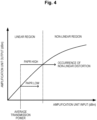
Fig. 4 is a graph exemplifying a relationship between amplification characteristics of the amplification unit and a magnitude of a PAPR. -
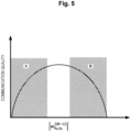
Fig. 5 is a graph illustrating communication quality with respect to a magnitude of a tap coefficient in precoding. -
Fig. 6 is a diagram illustrating a relationship between a threshold value α used by the transmission device according to the embodiment and a tap length M used for precoding. -
Fig. 7 is a functional block diagram illustrating functions of the transmission device according to the embodiment. -
Fig. 8 is a flowchart illustrating an operation example of the transmission device according to the embodiment. - Hereinafter, an embodiment of a wireless communication system will be described with reference to the drawings.
Fig. 1 is a diagram illustrating a configuration example of awireless communication system 1 according to the embodiment. As illustrated inFig. 1 , thewireless communication system 1 is, for example, a multiple input multiple output (MIMO) system in which a transmission device 2 performs MIMO transmission to a reception device 4. - Although the MIMO system is described as an example here, the wireless communication system according to an embodiment is not limited to a MIMO system, and may be a single input single output (SISO) system or the like as long as it is a system that performs precoding using a finite impulse response (FIR) filter.
- The transmission device 2 includes a plurality of antennas, precodes multiple streams of a transmission signal in a time domain, and performs MIMO transmission to the reception device 4. The transmission device 2 transmits a training signal for calculating communication path information (for example, channel state information (CSI)) to the reception device 4.
- The reception device 4 receives the multiple streams transmitted by the transmission device 2, and feeds quality information of a received signal back to the transmission device 2. The quality information of the received signal fed back from the reception device 4 to the transmission device 2 includes, for example, a channel quality indicator (CQI), a precoding matrix indicator (PMI), and the like. Further, the reception device 4 calculates communication path information by using the received training signal, and transmits the calculated communication path information to the transmission device 2.
- Note that the communication path information may be known or unknown to the transmission device 2. The transmission device 2 and the reception device 4 may have the same function to perform transmission and reception.
- Here, in order to facilitate understanding of the configuration of the transmission device according to the embodiment, a configuration example of a
transmission device 2a of a comparative example will be described.Fig. 2 is a functional block diagram illustrating functions of thetransmission device 2a of the comparative example. - As illustrated in
Fig. 2 , thetransmission device 2a of the comparative example includes a plurality of informationbit generation units 20, a plurality ofmodulation units 21, aprecoding unit 22, a plurality of D/A conversion units 23, a plurality of transmissionpower control units 24, a plurality ofamplification units 25, and a plurality ofantennas 26. Note that thetransmission device 2a can configure thewireless communication system 1 instead of the transmission device 2 illustrated inFig. 1 . - Each of the information
bit generation units 20 generates an information bit (data signal) that will be a transmission signal, and outputs the information bit to themodulation unit 21. Each data signal generated by the informationbit generation unit 20 serves as a stream. - Each of the
modulation units 21 modulates the data signal input from the informationbit generation unit 20 according to a predetermined modulation method, and outputs the modulated data signal to theprecoding unit 22. Examples of the modulation method include quadrature phase shift keying (QPSK) in which one symbol has four values, quadrature amplitude modulation (16QAM) in which one symbol has 16 values, and 64QAM in which one symbol has 64 values. - The
precoding unit 22 precodes multiple streams of a data signal (transmission signal) in the time domain by using an FIR filter and outputs the respective precoded streams to the plurality of D/A conversion units 23. Whenprecoding unit 22 performs precoding, a PAPR increases. - Each of the D/
A conversion units 23 performs D/A conversion on the stream input from theprecoding unit 22, and outputs the converted stream to the transmissionpower control unit 24. - Each of the transmission
power control units 24 controls the transmission power of the stream input from the D/A conversion unit 23 and outputs the stream to theamplification unit 25. That is, the plurality of transmissionpower control units 24 respectively control the transmission powers of the multiple streams precoded by theprecoding units 22. - The plurality of
amplification units 25 respectively amplify the multiple streams precoded by theprecoding units 22 according to the control of the transmissionpower control units 24, and radiate the multiple streams via theantenna 26. -
Fig. 3 is a diagram illustrating amplification characteristics of theamplification unit 25.Fig. 3(a) is a graph exemplifying amplification characteristics of theamplification unit 25.Fig. 3(b) is a diagram exemplifying a constellation of a transmission signal amplified by theamplification unit 25. - As illustrated in
Fig. 3(a) , theamplification unit 25 has a linear region in which an input is amplified and output in proportion to the input, and a non-linear region in which an excessive input is nonlinearly amplified. - As illustrated in
Fig. 3(b) , no distortion occurs in a transmission constellation in a case where theamplification unit 25 amplifies a data signal in the linear region, but distortion occurs in a transmission constellation in a case where theamplification unit 25 amplifies a data signal in the non-linear region. When distortion occurs in the transmission constellation, streams are not orthogonal to each other, and inter-stream interference occurs. -
Fig. 4 is a graph exemplifying a relationship between the amplification characteristics of theamplification unit 25 and a magnitude of the PAPR. Even if an average transmission power input to theamplification unit 25 is the same, when the PAPR is high, a larger peak power is generated than when the PAPR is low. - In a case where a transmission signal having the same average transmission power is input to the
amplification unit 25, even if a transmission signal is always amplified in the linear region when the PAPR is low, a transmission signal may be amplified in the non-linear region when the PAPR is high, and thus non-linear distortion may occur in the transmission constellation. - Therefore, a transmission device of a wireless communication system according to an embodiment that will be described later is configured to be able to control a tap length in precoding such that the quality of wireless communication can be improved even if a channel state varies.
- When a channel state changes, a tap coefficient changes. For example, a transfer function between an nt-th transmission antenna and an nr-th reception antenna in a case where a CIR length is L is expressed by the following Formula (1).
[Math. 1]
- Further, a transfer function of an FIR filter between an st-th transmission stream and an nt-th transmission antenna is expressed by the following Formula (2).
[Math. 2]
- Here, when L < M and the following Formula (3) is established, a magnitude of the tap coefficient shown in the following Formula (4) is small, and the tap length may be excessive.
[Math. 3]

- When L > M and the following Formula (5) is established, a magnitude of the tap coefficient shown in the above Formula (4) is large, and the tap length may be insufficient.
[Math. 5]
-
Fig. 5 is a graph illustrating a communication quality with respect to a magnitude of a tap coefficient in precoding. Here, a region A illustrated inFig. 5 is a region in which and the quality degradation due to nonlinear distortion caused by a small magnitude of the tap coefficient and a high PAPR is dominant. A region B is a region in which quality degradation due to inter-stream interference and inter-symbol interference caused by a large magnitude of the tap coefficient and an insufficient tap length is dominant. - That is, even if the tap coefficient is too small or too large, the communication quality deteriorates. Therefore, the transmission device of the wireless communication system according to an embodiment is configured to provide a threshold value a for the magnitude of the tap coefficient and control the tap length in the precoding by using the threshold value α.
-
Fig. 6 is a diagram illustrating a relationship between the threshold value α used by the transmission device according to the embodiment and the tap length M used for precoding. In thewireless communication system 1, the threshold value α may be determined while measuring the reception quality before communication, or may be updated during communication. In thewireless communication system 1, the threshold value a may be determined in advance on the basis of a system design value (characteristics of theamplification unit 25 used by the transmission device 2, desired BER characteristics, or the like). - For example, the transmission device according to the embodiment provides the threshold value α for a magnitude of the tap coefficient shown in the following Formula (6), calculates the maximum m that satisfies the following Formula (7), and uses m + 1 as the tap length M.
[Math. 6]

- The transmission device according to the embodiment may determine the tap length M by calculating the minimum m that satisfies the following Formula (8).
[Math. 8]
- The transmission device according to the embodiment may determine the tap length by using the value shown in the following Formula (9) or a magnitude of a tap coefficient converted into another manageable form instead of using the magnitude of the tap coefficient shown in the above Formula (4).
[Math. 9]
- For example, the transmission device according to the embodiment may, instead of using the magnitude of the tap coefficient without any change, perform normalization with, for example, the maximum tap coefficient as shown in the following Formula (10) and determine a threshold value for a relative value or the like.
[Math. 10]
- Next, a specific configuration example of a
transmission device 2b according to an embodiment will be described.Fig. 7 is a functional block diagram exemplifying functions of thetransmission device 2b according to the embodiment. - As illustrated in
Fig. 7 , thetransmission device 2b according to the embodiment includes a plurality of information bitgeneration units 20, a plurality ofmodulation units 21, aprecoding unit 22, a plurality of D/A conversion units 23, a plurality of transmissionpower control units 24, a plurality ofamplification units 25, a plurality ofantennas 26, a switchingunit 27, areception unit 28, a communication pathinformation acquisition unit 29, aweight calculation unit 30, a qualityinformation acquisition unit 31, a thresholdvalue calculation unit 32, a taplength control unit 33, and a thresholdvalue storage unit 34. - Note that, in the
transmission device 2b illustrated inFig. 7 , substantially the same constituents as those of thetransmission device 2a illustrated inFig. 2 are denoted by the same reference numerals. Thetransmission device 2b can configure thewireless communication system 1 instead of the transmission device 2 illustrated inFig. 1 . - The switching
unit 27 has a function of switching between transmission and reception performed via theantenna 26, transmits an output signal of theamplification unit 25 from theantenna 26, and outputs a signal received by theantenna 26 to thereception unit 28. - The
reception unit 28 processes the signal received via theantenna 26, and outputs the processed signal to the communication pathinformation acquisition unit 29 or the qualityinformation acquisition unit 31. - The communication path
information acquisition unit 29 acquires communication path information based on a training signal from the signal processed by thereception unit 28 for a communication path between the transmission device 2 and the reception device 4, and outputs the communication path information to theweight calculation unit 30 and the thresholdvalue calculation unit 32. - The
weight calculation unit 30 calculates a precoding weight for theprecoding unit 22 for each communication path by using the communication path information acquired by the communication pathinformation acquisition unit 29, and outputs the communication path information and the weight to the taplength control unit 33. - The quality
information acquisition unit 31 acquires quality information from the signal processed by thereception unit 28, and outputs the quality information to the thresholdvalue calculation unit 32. Note that the quality information includes an SNR or a BER acquired by the reception device 4 by using the training signal (known signal) transmitted by the transmission device 2, and includes the influence of non-linear distortion due to theamplification unit 25 of the transmission device 2 or inter-stream interference due to insufficient precoding. - The threshold
value calculation unit 32 calculates the above threshold value a on the basis of the quality information acquired by the qualityinformation acquisition unit 31, and outputs the threshold value α to the taplength control unit 33. - The tap
length control unit 33 performs control for changing a tap length in theprecoding unit 22 such that the tap length is decreased in a case where a magnitude of the last tap coefficient of theprecoding unit 22 is small and the tap length is increased in a case where the magnitude is large with respect to the threshold value a calculated on the basis of the quality information of the reception signal fed back from the reception device 4 that has received the stream amplified by theamplification unit 25 or the quality information of the reception signal calculated by using at least the characteristics of theamplification unit 25. - The tap
length control unit 33 may perform control for changing the tap length in theprecoding unit 22 by using the threshold value α or the like stored in the thresholdvalue storage unit 34 that will be described later. The taplength control unit 33 performs control for changing the tap length in theprecoding unit 22 every time theweight calculation unit 30 calculates the precoding weight by using the communication path information. - The threshold
value storage unit 34 stores the threshold value α and the like calculated in advance according to the characteristics of theamplification unit 25 and the like, and outputs the threshold value to the taplength control unit 33 according to access from the taplength control unit 33. - Next, an operation example of the
transmission device 2b according to the embodiment will be described.Fig. 8 is a flowchart illustrating an operation example of thetransmission device 2b according to the embodiment. - As illustrated in
Fig. 8 , in step 100 (S100), thetransmission device 2b transmits a training signal to the reception device 4, and the communication pathinformation acquisition unit 29 acquires the communication path information from the reception device 4. - In step 102 (S102), in the
transmission device 2b, theweight calculation unit 30 calculates a precoding weight. - In step 104 (S104), in the
transmission device 2b, the taplength control unit 33 sets a tap length in theprecoding unit 22 on the basis of the threshold value o. - In step 106 (S106), the
transmission device 2b performs precoding with the tap length set in theprecoding unit 22, and returns to the process in S100. - As described above, since the
transmission device 2b according to the embodiment controls the tap length on the basis of the threshold value, the quality of the wireless communication can be improved even if a channel state varies. - The reception device 4 illustrated in
Fig. 1 may also perform processes and calculate a threshold value in a similar manner to the transmission device 2 according to amplification characteristics or the like in the reception device 4. - Note that some or all of the units configuring the
transmission device 2b in the above embodiment may be configured by hardware, or may be configured by causing a processor to execute a program. - In a case where some or all of the units configuring the
transmission device 2b are configured by causing a processor to execute a program, the program may be recorded in a recording medium and supplied, or may be supplied via a network. -
- 1
- Wireless communication system
- 2, 2a, 2b
- Transmission device
- 4
- Reception device
- 20
- Information bit generation unit
- 21
- Modulation unit
- 22
- Precoding unit
- 23
- D/A conversion unit
- 24
- Transmission power control unit
- 25
- Amplification unit
- 26
- Antenna
- 27
- Switching Unit
- 28
- Reception unit
- 29
- Communication path information acquisition unit
- 30
- Weight calculation unit
- 31
- Quality information acquisition unit
- 32
- Threshold value calculation unit
- 33
- Tap length control unit
- 34
- Threshold value storage unit
Claims (6)
- A wireless communication method of transmitting a signal from a transmission device to a reception device, the method comprising:a precoding step of precoding a stream of a transmission signal in a time domain by using an FIR filter;a transmission power control step of controlling a transmission power of the precoded stream;an amplification step of amplifying the precoded stream such that the controlled transmission power is obtained; anda tap length control step of performing control for changing a tap length in the precoding step such that the tap length is decreased in a case where a magnitude of a last tap coefficient in the precoding step is small and the tap length is increased in a case where the magnitude is large, with respect to a threshold value calculated on the basis of quality information of a received signal fed back from the reception device that has received the amplified stream or quality information of a received signal calculated by using at least characteristics of an amplification unit of the transmission device.
- The wireless communication method according to claim 1, further comprising:a communication path information acquisition step of acquiring communication path information based on a training signal for a communication path between the transmission device and the reception device; anda weight calculating step of calculating a precoding weight in the precoding step by using the communication path information, whereinin the tap length control step, control for changing the tap length in the precoding step is performed each time a precoding weight is calculated by using the communication path information.
- A wireless communication system that transmits a signal from a transmission device to a reception device, the wireless communication system comprising:a precoding unit that precodes a stream of a transmission signal in a time domain by using an FIR filter;a transmission power control unit that controls a transmission power of the stream precoded by the precoding unit;an amplification unit that amplifies the stream precoded by the precoding unit under control of the transmission power control unit; anda tap length control unit that performs control for changing a tap length in the precoding unit such that the tap length is decreased in a case where a magnitude of a last tap coefficient in the precoding unit is small and the tap length is increased in a case where the magnitude is large, with respect to a threshold value calculated on the basis of quality information of a received signal fed back from the reception device that has received the stream amplified by the amplification unit or quality information of a received signal calculated by using at least characteristics of the amplification unit.
- The wireless communication system according to claim 3, further comprising:a communication path information acquisition unit that acquires communication path information based on a training signal for a communication path between the transmission device and the reception device; anda weight calculation unit that calculates a precoding weight in the precoding unit by using the communication path information, whereinthe tap length control unit performs control for changing the tap length in the precoding unit each time the weight calculation unit calculates a precoding weight by using the communication path information.
- A transmission device comprising:a precoding unit that precodes a stream of a transmission signal in a time domain by using an FIR filter;a transmission power control unit that controls a transmission power of the stream precoded by the precoding unit;an amplification unit that amplifies the stream precoded by the precoding unit under control of the transmission power control unit; anda tap length control unit that performs control for changing a tap length in the precoding unit such that the tap length is decreased in a case where a magnitude of a last tap coefficient in the precoding unit is small and the tap length is increased in a case where the magnitude is large, with respect to a threshold value calculated on the basis of quality information of a received signal fed back from the reception device that has received the stream amplified by the amplification unit or quality information of a received signal calculated by using at least characteristics of the amplification unit.
- The transmission device according to claim 5, further comprising:a communication path information acquisition unit that acquires communication path information based on a training signal for a communication path with the reception device; anda weight calculation unit that calculates a precoding weight in the precoding unit by using the communication path information, whereinthe tap length control unit performs control for changing the tap length in the precoding unit each time the weight calculation unit calculates a precoding weight by using the communication path information.
Applications Claiming Priority (1)
| Application Number | Priority Date | Filing Date | Title |
|---|---|---|---|
| PCT/JP2021/031602 WO2023026492A1 (en) | 2021-08-27 | 2021-08-27 | Wireless communication method, wireless communication system, and transmission device |
Publications (3)
| Publication Number | Publication Date |
|---|---|
| EP4395192A1 true EP4395192A1 (en) | 2024-07-03 |
| EP4395192A4 EP4395192A4 (en) | 2025-06-11 |
| EP4395192B1 EP4395192B1 (en) | 2026-03-18 |
Family
ID=85322604
Family Applications (1)
| Application Number | Title | Priority Date | Filing Date |
|---|---|---|---|
| EP21955101.7A Active EP4395192B1 (en) | 2021-08-27 | 2021-08-27 | Wireless communication method, wireless communication system, and transmitter |
Country Status (4)
| Country | Link |
|---|---|
| US (1) | US12457135B2 (en) |
| EP (1) | EP4395192B1 (en) |
| JP (1) | JP7613596B2 (en) |
| WO (1) | WO2023026492A1 (en) |
Families Citing this family (1)
| Publication number | Priority date | Publication date | Assignee | Title |
|---|---|---|---|---|
| WO2023162104A1 (en) * | 2022-02-24 | 2023-08-31 | 日本電信電話株式会社 | Radio wave direction-of-arrival estimation device and radio wave direction-of-arrival estimation method |
Family Cites Families (14)
| Publication number | Priority date | Publication date | Assignee | Title |
|---|---|---|---|---|
| JP4097430B2 (en) * | 1999-07-28 | 2008-06-11 | 富士通株式会社 | Wireless device with distortion compensation function |
| US20030086486A1 (en) | 2001-07-31 | 2003-05-08 | Graziano Michael J. | Method and system for determining maximum power backoff using frequency domain geometric signal to noise ratio |
| JP3990974B2 (en) * | 2002-11-26 | 2007-10-17 | 株式会社日立コミュニケーションテクノロジー | Peak factor reduction device |
| CN1255938C (en) * | 2002-12-10 | 2006-05-10 | 株式会社Ntt都科摩 | Linear power amplifying method and linear power amplifier |
| US8977141B2 (en) * | 2011-02-07 | 2015-03-10 | Nippon Telegraph And Telephone Corporation | Digital signal processing apparatus |
| WO2012109529A1 (en) * | 2011-02-11 | 2012-08-16 | Interdigital Patent Holdings, Inc. | Method and apparatus for uplink closed loop transmit diversity transmission initial access |
| US10826583B2 (en) * | 2013-12-20 | 2020-11-03 | RF DSP Inc. | Adaptive precoding in a MIMO wireless communication system |
| JP2017060138A (en) * | 2015-09-18 | 2017-03-23 | 富士通株式会社 | Wireless communication apparatus, wireless communication system, and transmission data control method |
| JP2017069688A (en) | 2015-09-29 | 2017-04-06 | パナソニックIpマネジメント株式会社 | Transmitting apparatus, receiving apparatus, and communication method using them |
| WO2017145232A1 (en) * | 2016-02-22 | 2017-08-31 | 三菱電機株式会社 | Transmission apparatus, reception apparatus, control station, communication system, and transmission precoding method |
| CN109257079A (en) | 2017-07-14 | 2019-01-22 | 索尼公司 | Wireless communications method and wireless telecom equipment |
| JP7196687B2 (en) | 2019-02-26 | 2022-12-27 | 日本電信電話株式会社 | Wireless communication system, wireless communication method, transmitting station device and receiving station device |
| JP7180514B2 (en) | 2019-04-11 | 2022-11-30 | 日本電信電話株式会社 | Wireless communication system, wireless communication method, transmitting station device and receiving station device |
| US11799547B2 (en) | 2019-09-17 | 2023-10-24 | Nippon Telegraph And Telephone Corporation | Signal processing apparatus, signal processing method, and program |
-
2021
- 2021-08-27 US US18/686,892 patent/US12457135B2/en active Active
- 2021-08-27 EP EP21955101.7A patent/EP4395192B1/en active Active
- 2021-08-27 WO PCT/JP2021/031602 patent/WO2023026492A1/en not_active Ceased
- 2021-08-27 JP JP2023543627A patent/JP7613596B2/en active Active
Also Published As
| Publication number | Publication date |
|---|---|
| US20240356787A1 (en) | 2024-10-24 |
| JPWO2023026492A1 (en) | 2023-03-02 |
| US12457135B2 (en) | 2025-10-28 |
| EP4395192A4 (en) | 2025-06-11 |
| EP4395192B1 (en) | 2026-03-18 |
| JP7613596B2 (en) | 2025-01-15 |
| WO2023026492A1 (en) | 2023-03-02 |
Similar Documents
| Publication | Publication Date | Title |
|---|---|---|
| USRE47732E1 (en) | System and method for antenna diversity using equal power joint maximal ratio combining | |
| US8917788B2 (en) | Wireless communication system, base station apparatus, and mobile station apparatus | |
| US8761834B2 (en) | Method and apparatus for antenna selection and power control in a multiple input multiple output wireless communication system | |
| EP1540830B1 (en) | System and method for multiple-input multiple-output (mimo) radio communication | |
| EP4243477B1 (en) | Wireless communication apparatus and wireless communication method | |
| EP2449694B1 (en) | Method and arrangement for adapting a signal in a wireless communications network | |
| CN101582712B (en) | Method for realizing precoding and method for generating precoding matrices | |
| EP4395192B1 (en) | Wireless communication method, wireless communication system, and transmitter | |
| US11736168B2 (en) | Wireless communication system, wireless communication method, transmitting station device and receiving station device | |
| US20230262485A1 (en) | Method and Apparatus to Control and Process a Plurality of Radar Sensors and Radio Units | |
| US12413274B2 (en) | Wireless communication system, wireless communication method, and transmitter | |
| US20220278721A1 (en) | Wireless communication system, wireless communication method, transmitting station device and receiving station device | |
| US20250112810A1 (en) | Wireless communication method, wireless communication system, and transmission device | |
| JP5901868B1 (en) | Wireless transmission device | |
| US20250158857A1 (en) | Wireless communication method, wireless communication system, and transmission device | |
| US20250141726A1 (en) | Wireless communication method, wireless communication system, and transmission device | |
| WO2023157133A1 (en) | Wireless communication method, wireless communication system, and transmission device | |
| EP4693896A1 (en) | Digital pre-distortion coefficient estimating device and operating method thereof | |
| Qi et al. | Impact of HPA nonlinearity on MIMO systems with quantized equal gain transmission | |
| KR100656786B1 (en) | Base station system having error correction function of multi-channel receiver and method thereof | |
| GB2466708A (en) | A MIMO transmitter adapts power allocation to antennas depending on whether the transmission is non-MIMO, MIMO rank-1 or MIMO-rank-2 | |
| JP2022138008A (en) | Transmission antenna selection device, transmission antenna selection method, and transmission antenna selection program | |
| KR20240102444A (en) | SU-MISO system with nonlinear PA | |
| Fayad | Analysis and Compensationfor Clipping-like Distortion of the Transmitted Signal in Massive MIMO Systems |
Legal Events
| Date | Code | Title | Description |
|---|---|---|---|
| STAA | Information on the status of an ep patent application or granted ep patent |
Free format text: STATUS: THE INTERNATIONAL PUBLICATION HAS BEEN MADE |
|
| PUAI | Public reference made under article 153(3) epc to a published international application that has entered the european phase |
Free format text: ORIGINAL CODE: 0009012 |
|
| STAA | Information on the status of an ep patent application or granted ep patent |
Free format text: STATUS: REQUEST FOR EXAMINATION WAS MADE |
|
| 17P | Request for examination filed |
Effective date: 20240220 |
|
| AK | Designated contracting states |
Kind code of ref document: A1 Designated state(s): AL AT BE BG CH CY CZ DE DK EE ES FI FR GB GR HR HU IE IS IT LI LT LU LV MC MK MT NL NO PL PT RO RS SE SI SK SM TR |
|
| DAV | Request for validation of the european patent (deleted) | ||
| DAX | Request for extension of the european patent (deleted) | ||
| A4 | Supplementary search report drawn up and despatched |
Effective date: 20250513 |
|
| RIC1 | Information provided on ipc code assigned before grant |
Ipc: H04B 1/04 20060101ALI20250507BHEP Ipc: H04B 7/0456 20170101AFI20250507BHEP |
|
| RAP3 | Party data changed (applicant data changed or rights of an application transferred) |
Owner name: NTT, INC. |
|
| GRAP | Despatch of communication of intention to grant a patent |
Free format text: ORIGINAL CODE: EPIDOSNIGR1 |
|
| STAA | Information on the status of an ep patent application or granted ep patent |
Free format text: STATUS: GRANT OF PATENT IS INTENDED |
|
| INTG | Intention to grant announced |
Effective date: 20251209 |
|
| GRAS | Grant fee paid |
Free format text: ORIGINAL CODE: EPIDOSNIGR3 |
|
| GRAA | (expected) grant |
Free format text: ORIGINAL CODE: 0009210 |
|
| STAA | Information on the status of an ep patent application or granted ep patent |
Free format text: STATUS: THE PATENT HAS BEEN GRANTED |
|
| AK | Designated contracting states |
Kind code of ref document: B1 Designated state(s): AL AT BE BG CH CY CZ DE DK EE ES FI FR GB GR HR HU IE IS IT LI LT LU LV MC MK MT NL NO PL PT RO RS SE SI SK SM TR |
|
| REG | Reference to a national code |
Ref country code: CH Ref legal event code: F10 Free format text: ST27 STATUS EVENT CODE: U-0-0-F10-F00 (AS PROVIDED BY THE NATIONAL OFFICE) Effective date: 20260318 Ref country code: GB Ref legal event code: FG4D |
|
| REG | Reference to a national code |
Ref country code: IE Ref legal event code: FG4D |
|
| REG | Reference to a national code |
Ref country code: DE Ref legal event code: R096 Ref document number: 602021050433 Country of ref document: DE |