EP4395135A1 - Coil substrate, motor coil substrate, and motor - Google Patents
Coil substrate, motor coil substrate, and motor Download PDFInfo
- Publication number
- EP4395135A1 EP4395135A1 EP22861204.0A EP22861204A EP4395135A1 EP 4395135 A1 EP4395135 A1 EP 4395135A1 EP 22861204 A EP22861204 A EP 22861204A EP 4395135 A1 EP4395135 A1 EP 4395135A1
- Authority
- EP
- European Patent Office
- Prior art keywords
- coil
- wires
- inter
- face
- board
- Prior art date
- Legal status (The legal status is an assumption and is not a legal conclusion. Google has not performed a legal analysis and makes no representation as to the accuracy of the status listed.)
- Pending
Links
Images



Classifications
-
- H—ELECTRICITY
- H02—GENERATION; CONVERSION OR DISTRIBUTION OF ELECTRIC POWER
- H02K—DYNAMO-ELECTRIC MACHINES
- H02K3/00—Details of windings
- H02K3/04—Windings characterised by the conductor shape, form or construction, e.g. with bar conductors
- H02K3/26—Windings characterised by the conductor shape, form or construction, e.g. with bar conductors consisting of printed conductors
-
- H—ELECTRICITY
- H01—ELECTRIC ELEMENTS
- H01F—MAGNETS; INDUCTANCES; TRANSFORMERS; SELECTION OF MATERIALS FOR THEIR MAGNETIC PROPERTIES
- H01F5/00—Coils
- H01F5/003—Printed circuit coils
-
- H—ELECTRICITY
- H02—GENERATION; CONVERSION OR DISTRIBUTION OF ELECTRIC POWER
- H02K—DYNAMO-ELECTRIC MACHINES
- H02K3/00—Details of windings
- H02K3/04—Windings characterised by the conductor shape, form or construction, e.g. with bar conductors
- H02K3/28—Layout of windings or of connections between windings
-
- H—ELECTRICITY
- H02—GENERATION; CONVERSION OR DISTRIBUTION OF ELECTRIC POWER
- H02K—DYNAMO-ELECTRIC MACHINES
- H02K3/00—Details of windings
- H02K3/46—Fastening of windings on the stator or rotor structure
- H02K3/47—Air-gap windings, i.e. iron-free windings
-
- H—ELECTRICITY
- H02—GENERATION; CONVERSION OR DISTRIBUTION OF ELECTRIC POWER
- H02K—DYNAMO-ELECTRIC MACHINES
- H02K2203/00—Specific aspects not provided for in the other groups of this subclass relating to the windings
- H02K2203/03—Machines characterised by the wiring boards, i.e. printed circuit boards or similar structures for connecting the winding terminations
-
- H—ELECTRICITY
- H02—GENERATION; CONVERSION OR DISTRIBUTION OF ELECTRIC POWER
- H02K—DYNAMO-ELECTRIC MACHINES
- H02K2213/00—Specific aspects, not otherwise provided for and not covered by codes H02K2201/00 - H02K2211/00
- H02K2213/03—Machines characterised by numerical values, ranges, mathematical expressions or similar information
-
- H—ELECTRICITY
- H05—ELECTRIC TECHNIQUES NOT OTHERWISE PROVIDED FOR
- H05K—PRINTED CIRCUITS; CASINGS OR CONSTRUCTIONAL DETAILS OF ELECTRIC APPARATUS; MANUFACTURE OF ASSEMBLAGES OF ELECTRICAL COMPONENTS
- H05K1/00—Printed circuits
- H05K1/02—Details
- H05K1/0277—Bendability or stretchability details
- H05K1/028—Bending or folding regions of flexible printed circuits
-
- H—ELECTRICITY
- H05—ELECTRIC TECHNIQUES NOT OTHERWISE PROVIDED FOR
- H05K—PRINTED CIRCUITS; CASINGS OR CONSTRUCTIONAL DETAILS OF ELECTRIC APPARATUS; MANUFACTURE OF ASSEMBLAGES OF ELECTRICAL COMPONENTS
- H05K1/00—Printed circuits
- H05K1/16—Printed circuits incorporating printed electric components, e.g. printed resistors, capacitors or inductors
- H05K1/165—Printed circuits incorporating printed electric components, e.g. printed resistors, capacitors or inductors incorporating printed inductors
-
- Y—GENERAL TAGGING OF NEW TECHNOLOGICAL DEVELOPMENTS; GENERAL TAGGING OF CROSS-SECTIONAL TECHNOLOGIES SPANNING OVER SEVERAL SECTIONS OF THE IPC; TECHNICAL SUBJECTS COVERED BY FORMER USPC CROSS-REFERENCE ART COLLECTIONS [XRACs] AND DIGESTS
- Y02—TECHNOLOGIES OR APPLICATIONS FOR MITIGATION OR ADAPTATION AGAINST CLIMATE CHANGE
- Y02T—CLIMATE CHANGE MITIGATION TECHNOLOGIES RELATED TO TRANSPORTATION
- Y02T10/00—Road transport of goods or passengers
- Y02T10/60—Other road transportation technologies with climate change mitigation effect
- Y02T10/64—Electric machine technologies in electromobility
Definitions
- a motor coil board of the present invention is formed by winding the coil board of the present invention into a cylindrical shape.
- the first face is arranged on an inner circumferential side and the second face is arranged on an outer circumferential side.
- a first wire 30UF constituting a half turn of one turn is formed on the first face 10F side
- a second wire 30UB constituting a remaining half turn is formed on the second face 10B side
- adjacent turns are arranged offset from each other.
- the coil 20U comprises three turns of wires.
- the first wire 30UF and the second wire 30UB constituting each turn are electrically connected through via conductors 31U penetrating the flexible board 10.
- the bottom portions of the second wires 30UB, 30VB are the parts of the second wires 30UB, 30VB touching the second face 10B.
- the distances TD, BD are 10 ⁇ m-50 ⁇ m (preferably 15 ⁇ m-30 ⁇ m), for example.
- the configurations of the coil board 2 ( fig. 1 and 2 ), the motor coil board 50 ( fig. 3 and 4 ), and the motor 100 ( fig. 5 ) of the embodiment are as described above.
- the inter-wire distance D1 between the first wires 32UF constituting the U-phase coil 22U and the first wires 32VF constituting the V-phase coil 22V is greater than the inter-wire distance D2 of the first wires 32UF constituting the coil 22U and the inter-wire distance D3 of the first wires 32VF constituting the coil 22V.
- the widths of the first wires 30UF, 30VF are largely equal to the widths of the second wires 32UB, 32VB.
- the inter-wire distance D2 is equal to the inter-wire distance D5.
- the inter-wire distance D3 is equal to the inter-wire distance D4.
- the inter-wire distance D1 is greater than the inter-wire distances D2 and D3.
- the inter-wire distance D4 is greater than the inter-wire distances D5 and D6.
- the inter-wire distance D1 may be greater than the inter-wire distance D4 or equal to the inter-wire distance D4.
- Fig. 6-8 show a first modified example of the embodiment.
- the arrangement of the wires constituting the coils 20U, 20V, 20W differs from that of the embodiment.
- Fig. 6 is a plan view showing a coil board 102 according to the first modified example.
- Fig. 7 is a bottom view showing the coil board 102 according to the first modified example.
- the flexible board 10 is provided with one set of three-phase coils 20U, 20V, 20W, as shown in fig. 6 and 7 .
- the flexible board 10 may be provided with 3Y (where Y is an integer of 2 or more) coils (i.e., two or more sets of three-phase coils) .
- the motor coil board 50 ( fig. 3 and 4 ) is formed by using the coil board 102 of the first modified example ( fig. 6-8 ), a distance is therefore maintained between the first wires 30UF constituting the coil 20U and the first wires 30VF constituting the adjacent coil 20V on the first face 10F on the inner circumferential side. A distance is likewise maintained between the second wires 30UB constituting the coil 20U and the second wires 30VB constituting the adjacent coil 20V on the second face 10B on the outer circumferential side also.
- the motor 100 is formed by using the coil board 102 comprising coils of multiple phases (three phases to be specific), the withstand voltage of the motor 100 is ensured, and a motor 100 having stable performance can be obtained.
- the widths of the first wires 30UF, 30VF in fig. 8 are largely equal to the widths of the second wires 30UB, 30VB.
- the inter-wire distance D8 is equal to the inter-wire distance D11.
- the inter-wire distance D9 is equal to the inter-wire distance D12.
- the inter-wire distance D7 is greater than the inter-wire distances D8 and D9.
- the inter-wire distance D10 is greater than the inter-wire distances D11 and D12.
- the inter-wire distance D7 may be greater than the inter-wire distance D10 or equal to the inter-wire distance D10.
- the coil board 102 is provided with coils of multiple phases comprising four or more phases.
Landscapes
- Engineering & Computer Science (AREA)
- Power Engineering (AREA)
- Windings For Motors And Generators (AREA)
- Parts Printed On Printed Circuit Boards (AREA)
Abstract
Description
- The technology disclosed in the present specification relates to a coil board, a motor coil board formed by using the coil board, and a motor formed by using the motor coil board.
- Patent Document 1 describes a coil board comprising a flexible board and spiral-shaped wires formed on both surfaces of the flexible board. A motor coil board is formed by winding the coil board into a cylindrical shape. A motor is formed by arranging the formed motor coil board on the inside of a cylindrical yoke, and arranging a rotary shaft and a magnet on the inside of the motor coil board.
- Patent Document 1:
JP 2020-61532 A - The coil board of Patent Document 1 may comprise a plurality of coils constituting three phases, namely a U phase, V phase and W phase. In that case, when the coil board is wound into a cylindrical shape, it is feasible that the wires of two adjacent coils constituting different phases will be close to each other. When a high voltage is applied, it is feasible that there will be a short circuit between the wires of the two adjacent coils constituting different phases.
- A coil board of the present invention comprises: a flexible board having a first face and a second face on the opposite side to the first face; and a plurality of coils formed by coil-shaped wires provided on the first face and coil-shaped wires provided on the second face. The plurality of coils include an Nth (N = 1, 2...) coil forming an Nth phase, and an N+1th coil forming an N+1th phase, the N+1th coil being arranged next to the Nth coil. An inter-wire distance between the wires constituting the Nth coil and the wires constituting the N+1th coil is greater than an inter-wire distance of the wires constituting the Nth coil and an inter-wire distance of the wires constituting the N+1th coil.
- In a coil board according to an embodiment of the present invention, the inter-wire distance between the wires constituting the Nth coil and the wires constituting the N+1th coil is greater than the inter-wire distance of the wires constituting the Nth coil and the inter-wire distance of the wires constituting the N+1th coil. When the coil board is wound into a cylindrical shape in order to form a motor coil board, a distance is therefore maintained between the wires constituting the Nth coil and the wires constituting the adjacent N+1th coil, and there is no contact between the wires. The occurrence of a short circuit between the Nth phase the N+1th phase is also suppressed when a high voltage is applied. When a motor is formed by using a coil board comprising coils of multiple phases, a withstand voltage of the motor is ensured and a motor having stable performance can be obtained.
- A motor coil board of the present invention is formed by winding the coil board of the present invention into a cylindrical shape. The first face is arranged on an inner circumferential side and the second face is arranged on an outer circumferential side.
- In a motor coil board according to an embodiment of the present invention, a distance is maintained between the wires constituting the Nth coil and the wires constituting the adjacent N+1th coil, and there is no contact between the wires, as indicated above. The occurrence of a short circuit between the Nth phase the N+1th phase is also suppressed when a high voltage is applied. When a motor is formed by using the motor coil board, a withstand voltage of the motor is ensured and a motor having stable performance can be obtained.
- A motor of the present invention is formed by arranging the motor coil board of the present invention on the inside of a cylindrical yoke, and arranging a rotary shaft and a magnet on the inside of the motor coil board.
- In a motor according to an embodiment of the present invention, the occurrence of a short circuit between the Nth phase the N+1th phase is also suppressed when a high voltage is applied. A withstand voltage of the motor is ensured and a motor having stable performance can be obtained.
-
- [
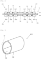
Fig. 1 ] is a plan view schematically showing a coil board according to an embodiment. - [
Fig. 2 ] is a view in cross section schematically showing a portion of the coil board according to an embodiment. - [
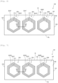
Fig. 3 ] is an oblique view schematically showing a motor coil board according to an embodiment. - [
Fig. 4 ] is an enlarged explanatory diagram of a portion offig. 3 . - [
Fig. 5 ] is a view in cross section schematically showing a motor according to an embodiment. - [
Fig. 6 ] is a plan view schematically showing a coil board according to a first modified example of the embodiment. - [
Fig. 7 ] is a bottom view schematically showing the coil board according to the first modified example of the embodiment. - [
Fig. 8 ] is a view in cross section schematically showing a portion of the coil board according to the first modified example. -
Fig. 1 is a plan view showing acoil board 2 according to an embodiment. Thecoil board 2 comprises aflexible board 10, and a plurality ofcoils coil board 2 is a coil board for a three-phase motor. Thecoils coils coils - The
flexible board 10 is a resin board comprising afirst face 10F and asecond face 10B on the opposite side to thefirst face 10F. Theflexible board 10 is formed by using an insulating resin such as polyimide or polyamide. Theflexible board 10 is capable of flexing. Theflexible board 10 is formed in a rectangular shape havingshort sides 10S andlong sides 10L. When a motor coil board 50 (seefig. 3 ) is formed by winding thecoil board 2 into a cylindrical shape, as will be described in detail later, thefirst face 10F is arranged on an inner circumferential side and thesecond face 10B is arranged on an outer circumferential side. - The
coils long sides 10L of theflexible board 10. As mentioned above, thecoils coils coils phase coils U-phase coils phase coils phase coils flexible board 10 is provided with sixcoils flexible board 10 may be provided with 3X (where X is an integer of 1 or 3 or more) coils (i.e., one set or three or more sets of three-phase coils). - In order to form the
coil 20U, a first wire 30UF constituting a half turn of one turn is formed on thefirst face 10F side, a second wire 30UB constituting a remaining half turn is formed on thesecond face 10B side, and adjacent turns are arranged offset from each other. Infig. 1 , thecoil 20U comprises three turns of wires. The first wire 30UF and the second wire 30UB constituting each turn are electrically connected through viaconductors 31U penetrating theflexible board 10. - In the same way, in order to form the
coil 20V, a first wire 30VF constituting a half turn of one turn is formed on thefirst face 10F side, a second wire 30VB constituting a remaining half turn is formed on thesecond face 10B side, and adjacent turns are arranged offset from each other. Thecoil 20V comprises three turns of wires. The first wire 30VF and the second wire 30VB constituting each turn are electrically connected through viaconductors 31V penetrating theflexible board 10. In order to form thecoil 20W, a first wire 30WF constituting a half turn of one turn is formed on thefirst face 10F side, a second wire 30WB constituting a remaining half turn is formed on thesecond face 10B side, and adjacent turns are arranged offset from each other. Thecoil 20W comprises three turns of wires. The first wire 30WF and the second wire 30WB constituting each turn are electrically connected through viaconductors 31W penetrating theflexible board 10. - The configuration of the
coils coils coil 22U is formed by means of first wires 32UF, second wires 32UB, and viaconductors 33U. Thecoil 22V is formed by means of first wires 32VF, second wires 32VB, and viaconductors 33V. Thecoil 22W is formed by means of first wires 32WF, second wires 32WB, and viaconductors 33W. - Portions of the second wires 30UB of the
coil 20U overlap, through theflexible board 10, portions of the first wires 32UF of theU-phase coil 22U of the adjacent set. Portions of the second wires 30VB of thecoil 20V overlap, through theflexible board 10, portions of the first wires 32VF of the V-phase coil 22V of the adjacent set. Portions of the second wires 30WB of thecoil 20W overlap, through theflexible board 10, portions of the first wires 32WF of the W-phase coil 22W of the adjacent set. The arrangement infig. 1 is an example, and in another modified example, portions of the second wires 30UB, 30VB, 30WB constituting thecoils coils - The
first face 10F and the first wires 30UF, 30VF, 30WF, 32UF, 32VF, 32WF are covered over by a resin insulating layer, although this is not shown in the drawings. Thesecond face 10B and the second wires 30UB, 30VB, 30WB, 32UB, 32VB, 32WB are likewise covered over by a resin insulating layer. -
Fig. 2 is a view in cross section of a portion of thecoil board 2 of the embodiment.Fig. 2 is a view in the cross section between II-II infig. 1 . As shown infig. 2 , an inter-wire distance D1 between the first wires 32UF constituting theU-phase coil 22U and the first wires 32VF constituting the V-phase coil 22V on thefirst face 10F side is greater than an inter-wire distance D2 of the first wires 32UF constituting thecoil 22U and an inter-wire distance D3 of the first wires 32VF constituting thecoil 22V. The inter-wire distance D2 and the inter-wire distance D3 are largely the same, but a difference commensurate with positions when thecoil board 2 is wound into a cylindrical shape may also be provided. - In the same way, an inter-wire distance D4 between the second wires 30UB constituting the
U-phase coil 20U and the second wires 30VB constituting the V-phase coil 20V on thesecond face 10B side is greater than an inter-wire distance D5 of the second wires 30UB constituting thecoil 20U and an inter-wire distance D6 of the second wires 30VB constituting thecoil 20V. The inter-wire distance D5 and the inter-wire distance D6 are largely the same, but a difference commensurate with positions when thecoil board 2 is wound into a cylindrical shape may also be provided. - Furthermore, the inter-wire distance D2 is greater than the inter-wire distance D5. The inter-wire distance D3 is greater than the inter-wire distance D6. The widths of the first wires 32UF, 32VF are smaller than the widths of the second wires 30UB, 30BV. The inter-wire distance D1 is therefore greater than the inter-wire distance D4.
- The example in
fig. 2 illustrates only a relationship of thecoil 20U (U phase) and thecoil 20V (V phase), and thecoil 22U (U phase) and thecoil 22V (V phase), but the relationships between adjacent coils of different phases (relationship of thecoil 20V (V phase) and thecoil 20W (W phase), and relationship of thecoil 20W (W phase) and thecoil 22U (U phase) of the adjacent set, etc.) are also the same as the relationship illustrated infig. 2 . -
Fig. 3 is an oblique view schematically showing amotor coil board 50 employing thecoil board 2 of the embodiment (fig. 1 and2 ). As shown infig. 3 , themotor coil board 50 for a motor is formed by winding thecoil board 2 of the embodiment (fig. 1 and2 ) into a cylindrical shape. When thecoil board 2 is wound into a cylindrical shape, it is wound in a circumferential direction about an axis parallel to theshort side 10S at one end, starting from one end of thelong side 10L (fig. 1 ). Thecoil board 2 is wound around multiple times. When it is wound into a cylindrical shape, thefirst face 10F is arranged on the inner circumferential side and thesecond face 10B is arranged on the outer circumferential side. -
Fig. 4 is an enlarged explanatory diagram of the part IV infig. 3 . As shown infig. 4 , a distance TD between top portions of the first wires 32UF of thecoil 22U and the first wires 32VF of thecoil 22V, which are arranged on the inner circumferential side, is largely equal to a distance BD between bottom portions of the second wires 30UB of thecoil 20U and the second wires 30VB of thecoil 20V, which are arranged on the outer circumferential side. The top portions of the first wires 32UF, 32VF are the parts of the first wires 32UF, 32VF at the greatest height from thefirst face 10F. The bottom portions of the second wires 30UB, 30VB are the parts of the second wires 30UB, 30VB touching thesecond face 10B. The distances TD, BD are 10 µm-50 µm (preferably 15 µm-30 µm), for example. -
Fig. 5 is a view in cross section schematically showing amotor 100 employing themotor coil board 50 of the embodiment (fig. 3 and4 ). Themotor 100 is formed by arranging themotor coil board 50 on the inside of ayoke 60, and arranging arotary shaft 80 and amagnet 70, which is fixed to therotary shaft 80, on the inside of themotor coil board 50. - The configurations of the coil board 2 (
fig. 1 and2 ), the motor coil board 50 (fig. 3 and4 ), and the motor 100 (fig. 5 ) of the embodiment are as described above. As shown infig. 2 , in thecoil board 2 of the embodiment, the inter-wire distance D1 between the first wires 32UF constituting theU-phase coil 22U and the first wires 32VF constituting the V-phase coil 22V is greater than the inter-wire distance D2 of the first wires 32UF constituting thecoil 22U and the inter-wire distance D3 of the first wires 32VF constituting thecoil 22V. The inter-wire distance D4 between the second wires 30UB constituting theU-phase coil 20U and the second wires 30VB constituting the V-phase coil 20V is greater than the inter-wire distance D5 of the second wires 30UB constituting thecoil 20U and the inter-wire distance D6 of the second wires 30VB constituting thecoil 20V. When the motor coil board 50 (fig. 3 and4 ) is formed by using thecoil board 2 of the embodiment, a distance is therefore maintained between the first wires 32UF constituting thecoil 22U and the first wires 32VF constituting theadjacent coil 22V on thefirst face 10F on the inner circumferential side, and there is no contact between the wires. A distance is likewise maintained between the second wires 30UB constituting thecoil 20U and the second wires 30VB constituting theadjacent coil 20V on thesecond face 10B on the outer circumferential side also. When themotor 100 is formed by using thecoil board 2 comprising coils of multiple phases (three phases to be specific), the withstand voltage of themotor 100 is ensured, and amotor 100 having stable performance can be obtained. - The
coil 20U and thecoil 20V infig. 2 , and thecoil 22U and thecoil 22V infig. 2 are an example of the "Nth coil" and the "N+1th coil". The inter-wire distances D1 and D4 are an example of the "inter-wire distance between the wires constituting the Nth coil and the wires constituting the N+1th coil". The inter-wire distances D2 and D5 are an example of the "inter-wire distance of the wires constituting the Nth coil". The inter-wire distances D3 and D6 are an example of the "inter-wire distance of the wires constituting the N+1th coil". - In different example 1 of the embodiment, the widths of the first wires 30UF, 30VF are largely equal to the widths of the second wires 32UB, 32VB. The inter-wire distance D2 is equal to the inter-wire distance D5. The inter-wire distance D3 is equal to the inter-wire distance D4. In this case also, the inter-wire distance D1 is greater than the inter-wire distances D2 and D3. The inter-wire distance D4 is greater than the inter-wire distances D5 and D6. The inter-wire distance D1 may be greater than the inter-wire distance D4 or equal to the inter-wire distance D4.
- In different example 2 of the embodiment, the
coil board 2 is provided with coils of multiple phases comprising four or more phases. In this case, the inter-wire distance between the wires constituting the Nth (N = 1, 2...) coil of the Nth phase and the wires constituting the N+1th coil of the N+1th phase is greater than the inter-wire distance of the wires constituting the Nth coil and the inter-wire distance of the wires constituting the N+1th coil. -
Fig. 6-8 show a first modified example of the embodiment. In the first modified example, the arrangement of the wires constituting thecoils Fig. 6 is a plan view showing acoil board 102 according to the first modified example.Fig. 7 is a bottom view showing thecoil board 102 according to the first modified example. In the first modified example, theflexible board 10 is provided with one set of three-phase coils fig. 6 and 7 . In another example, theflexible board 10 may be provided with 3Y (where Y is an integer of 2 or more) coils (i.e., two or more sets of three-phase coils) . - The
coil 20U constituting the U phase comprises: coil-shaped first wires 30UF provided on thefirst face 10F (fig. 6 ) and coil-shaped second wires 30UB provided on thesecond face 10B (fig. 7 ). The first wires 30UF and the second wires 30UB are electrically connected through a viaconductor 31U penetrating theflexible board 10. Thecoil 20V constituting the V phase likewise comprises first wires 30VF and second wires 30VB. The first wires 30VF and the second wires 30VB are electrically connected through a viaconductor 31V. Thecoil 20W constituting the W phase comprises first wires 30WF and second wires 30WB. The first wires 30WF and the second wires 30WB are electrically connected through a viaconductor 31W. - As shown in
fig. 6 , the first wires 30UF are formed in a spiral shape (hexagonal spiral shape) winding clockwise from the outer circumference toward the inner circumference. The viaconductor 31U is formed at an inner circumferential end of the first wires 30UF. As shown infig. 7 , the second wires 30UB are formed in a spiral shape (hexagonal spiral shape) winding counterclockwise from the outer circumference toward the inner circumference. The viaconductor 31U is formed at an inner circumferential end of the second wires 30UB. The first wires 30UF and the second wires 30UB are formed in spiral shapes with the same winding direction when seen from the same face. The first wires 30UF and the second wires 30UB function as onecoil 20U in which they are electrically connected in series. - The first wires 30VF and second wires 30VB and the first wires 30WF and second wires 30WB have the same relationship as that of the first wires 30UF and second wires 30UB. The first wires 30VF and second wires 30VB are formed in spiral shapes with the same winding direction when seen from the same face. The first wires 30VF and second wires 30VB function as one
coil 20V in which they are electrically connected in series. The first wires 30WF and second wires 30WB are formed in spiral shapes with the same winding direction when seen from the same face. The first wires 30WF and second wires 30WB function as onecoil 20W in which they are electrically connected in series. - Furthermore, the
first face 10F and the first wires 30UF, 30VF, 30WF are covered over by a resin insulating layer, although this is not shown in the drawings. Thesecond face 10B and the second wires 30UB, 30VB, 30WB are likewise covered over by a resin insulating layer. -
Fig. 8 is a view in cross section of a portion of thecoil board 102.Fig. 8 is a view in the cross section between VIII-VIII infig. 7 . A relationship of thecoil 20U (first wires 30UF and second wires 30UB) and thecoil 20V (first wires 30VF and second wires 30VB) will be described in detail with reference tofig. 8 .Fig. 3 shows a cross section of a portion of thecoil 20U and thecoil 20V, but thecoil 20V and thecoil 20W also have the same relationship. - As shown in
fig. 8 , the first wires 30UF on thefirst face 10F and the second wires 30UB on thesecond face 10B are overlapping through theflexible board 10 in a thickness direction (a vertical direction in the drawing). The first wires 30VF on thefirst face 10F and the second wires 30VB on thesecond face 10B are overlapping through theflexible board 10 in the thickness direction. - An inter-wire distance D7 between the first wires 30UF constituting the
U-phase coil 20U and the first wires 30VF constituting the V-phase coil 20V on thefirst face 10F side is greater than an inter-wire distance D8 of the first wires 30UF constituting thecoil 20U and an inter-wire distance D9 of the first wires 30VF constituting thecoil 20V. The inter-wire distance D8 and the inter-wire distance D9 are largely the same, but a difference commensurate with positions when thecoil board 102 is wound into a cylindrical shape may also be provided. - In the same way, an inter-wire distance D10 between the second wires 30UB constituting the
U-phase coil 20U and the second wires 30VB constituting the V-phase coil 20V on thesecond face 10B side is greater than an inter-wire distance D11 of the second wires 30UB constituting thecoil 20U and an inter-wire distance D12 of the second wires 30VB constituting thecoil 20V. The inter-wire distance D11 and the inter-wire distance D12 are largely the same, but a difference commensurate with positions when thecoil board 102 is wound into a cylindrical shape may also be provided. - Furthermore, the inter-wire distance D8 is greater than the inter-wire distance D11. The inter-wire distance D9 is greater than the inter-wire distance D12. The widths of the first wires 30UF, 30VF are smaller than the widths of the second wires 30UB, 30BV. The inter-wire distance D7 is therefore greater than the inter-wire distance D10.
- When the motor coil board 50 (
fig. 3 and4 ) is formed by using thecoil board 102 of the first modified example (fig. 6-8 ), a distance is therefore maintained between the first wires 30UF constituting thecoil 20U and the first wires 30VF constituting theadjacent coil 20V on thefirst face 10F on the inner circumferential side. A distance is likewise maintained between the second wires 30UB constituting thecoil 20U and the second wires 30VB constituting theadjacent coil 20V on thesecond face 10B on the outer circumferential side also. When themotor 100 is formed by using thecoil board 102 comprising coils of multiple phases (three phases to be specific), the withstand voltage of themotor 100 is ensured, and amotor 100 having stable performance can be obtained. - In different example 1 of the first modified example, the widths of the first wires 30UF, 30VF in
fig. 8 are largely equal to the widths of the second wires 30UB, 30VB. The inter-wire distance D8 is equal to the inter-wire distance D11. The inter-wire distance D9 is equal to the inter-wire distance D12. In this case also, the inter-wire distance D7 is greater than the inter-wire distances D8 and D9. The inter-wire distance D10 is greater than the inter-wire distances D11 and D12. The inter-wire distance D7 may be greater than the inter-wire distance D10 or equal to the inter-wire distance D10. - In different example 2 of the first modified example, the
coil board 102 is provided with coils of multiple phases comprising four or more phases. In this case, the inter-wire distance between the wires constituting the Nth (N = 1, 2...) coil of the Nth phase and the wires constituting the N+1th coil of the N+1th phase is greater than the inter-wire distance of the wires constituting the Nth coil and the inter-wire distance of the wires constituting the N+1th coil. -
- 2:
- Coil board
- 10:
- Flexible board
- 10F:
- First face
- 10B:
- Second face
- 20U, 20V, 20W:
- Coil
- 22U, 22V, 22W:
- Coil
- 50:
- Motor coil board
- 60:
- Yoke
- 70:
- Magnet
- 80:
- Rotary shaft
- 100:
- Motor
- 102:
- Coil board
Claims (4)
- A coil board comprising:a flexible board having a first face and a second face on the opposite side to the first face; anda plurality of coils formed by coil-shaped wires provided on the first face and coil-shaped wires provided on the second face,wherein the plurality of coils include an Nth (N = 1, 2...) coil forming an Nth phase, and an N+1th coil forming an N+1th phase, the N+1th coil being arranged next to the Nth coil, andan inter-wire distance between the wires constituting the Nth coil and the wires constituting the N+1th coil is greater than an inter-wire distance of the wires constituting the Nth coil and an inter-wire distance of the wires constituting the N+1th coil.
- The coil board of claim 1, wherein each of the plurality of coils comprises: a half-turn wire formed on the first face; a half-turn wire formed on the second face; and a via conductor which penetrates the flexible board and connects the half-turn wire on the first face and the half-turn wire on the second face.
- A motor coil board formed by winding the coil board of claim 1 into a cylindrical shape, wherein the first face is arranged on an inner circumferential side and the second face is arranged on an outer circumferential side.
- A motor formed by arranging the motor coil board of claim 3 on the inside of a cylindrical yoke, and arranging a rotary shaft and a magnet on the inside of the motor coil board.
Applications Claiming Priority (2)
| Application Number | Priority Date | Filing Date | Title |
|---|---|---|---|
| JP2021136207A JP2023030842A (en) | 2021-08-24 | 2021-08-24 | Coil substrate, coil substrate for motor, and motor |
| PCT/JP2022/031047 WO2023026916A1 (en) | 2021-08-24 | 2022-08-17 | Coil substrate, motor coil substrate, and motor |
Publications (2)
| Publication Number | Publication Date |
|---|---|
| EP4395135A1 true EP4395135A1 (en) | 2024-07-03 |
| EP4395135A4 EP4395135A4 (en) | 2025-08-27 |
Family
ID=85322095
Family Applications (1)
| Application Number | Title | Priority Date | Filing Date |
|---|---|---|---|
| EP22861204.0A Pending EP4395135A4 (en) | 2021-08-24 | 2022-08-17 | COIL SUBSTRATE, MOTOR COIL SUBSTRATE AND MOTOR |
Country Status (5)
| Country | Link |
|---|---|
| US (1) | US20240195252A1 (en) |
| EP (1) | EP4395135A4 (en) |
| JP (1) | JP2023030842A (en) |
| CN (1) | CN117813747A (en) |
| WO (1) | WO2023026916A1 (en) |
Families Citing this family (2)
| Publication number | Priority date | Publication date | Assignee | Title |
|---|---|---|---|---|
| JP2023022416A (en) * | 2021-08-03 | 2023-02-15 | イビデン株式会社 | Coil substrate, motor coil substrate, and motor |
| JP7436764B1 (en) | 2023-06-19 | 2024-02-22 | 株式会社Not’S | Coil units, coil assemblies and energy converters |
Family Cites Families (11)
| Publication number | Priority date | Publication date | Assignee | Title |
|---|---|---|---|---|
| JP3470372B2 (en) * | 1994-01-17 | 2003-11-25 | 株式会社安川電機 | Sheet coil |
| US20110140564A1 (en) * | 2009-12-10 | 2011-06-16 | Ibiden Co., Ltd. | Coil sheet, method for manufacturing coil sheet, coil sheet holder, method for attaching coil sheet, rotator of motor, and motor |
| CA2834736A1 (en) * | 2011-04-11 | 2012-10-18 | Allied Motion Technologies Inc. | Flexible winding for an electric motor and method of producing |
| CA2913502A1 (en) * | 2013-06-27 | 2014-12-31 | Universite Catholique De Louvain | Winding for a rotating electrical machine and method for designing such a winding |
| CN107112836B (en) * | 2015-01-07 | 2020-09-08 | 卢万天主教大学 | Winding for an electric machine |
| CN107394932A (en) * | 2017-07-10 | 2017-11-24 | 金华职业技术学院 | Flexible printed circuit board does the ultra micro DC brushless motor of stator winding |
| JP2020061532A (en) * | 2018-10-12 | 2020-04-16 | イビデン株式会社 | Coil board, coil board for motor, manufacturing method of motor and coil board |
| JP2020072551A (en) * | 2018-10-31 | 2020-05-07 | イビデン株式会社 | Coil substrate for motor and motor |
| JP2020114139A (en) * | 2019-01-16 | 2020-07-27 | イビデン株式会社 | Coil board and laminated coil board, motor coil board, and motor |
| JP2021048718A (en) * | 2019-09-19 | 2021-03-25 | イビデン株式会社 | Coil substrate for motor |
| JP2022043581A (en) * | 2020-09-04 | 2022-03-16 | イビデン株式会社 | Coil board and coil board for motor |
-
2021
- 2021-08-24 JP JP2021136207A patent/JP2023030842A/en active Pending
-
2022
- 2022-08-17 CN CN202280055524.3A patent/CN117813747A/en active Pending
- 2022-08-17 WO PCT/JP2022/031047 patent/WO2023026916A1/en not_active Ceased
- 2022-08-17 EP EP22861204.0A patent/EP4395135A4/en active Pending
-
2024
- 2024-02-20 US US18/581,985 patent/US20240195252A1/en active Pending
Also Published As
| Publication number | Publication date |
|---|---|
| US20240195252A1 (en) | 2024-06-13 |
| WO2023026916A1 (en) | 2023-03-02 |
| EP4395135A4 (en) | 2025-08-27 |
| JP2023030842A (en) | 2023-03-08 |
| CN117813747A (en) | 2024-04-02 |
Similar Documents
| Publication | Publication Date | Title |
|---|---|---|
| JP5532319B2 (en) | Stator for rotating electric machine and method for manufacturing the same | |
| US9712010B2 (en) | Motor having a cage wave stator winding | |
| EP2362526B1 (en) | Method for manufacturing a stator for an energy converting apparatus | |
| US8450899B2 (en) | Stator for electric rotating machine | |
| JP5586969B2 (en) | Rotating electric machine stator | |
| JP5488421B2 (en) | Rotating electric machine stator | |
| JP4558000B2 (en) | Continuous winding coil and stator | |
| US8471669B2 (en) | Disc-type coil | |
| US20220286006A1 (en) | Motor | |
| US20240195252A1 (en) | Coil substrate, motor coil substrate, and motor | |
| JP6293576B2 (en) | Stator for rotating electrical machine | |
| EP3297134B1 (en) | Rotary electrical machine stator | |
| EP4383527A1 (en) | Coil board, coil board for motor use, and motor | |
| CN114257011B (en) | Motor stator | |
| CN115443597A (en) | Stator with distributed winding coil structure and three-phase AC motor provided with the stator | |
| CN112838696B (en) | Machine assembly for an electric machine | |
| CN115411862A (en) | Stator | |
| EP4447280B1 (en) | Stator | |
| US20150372551A1 (en) | Structure of stator | |
| JP7744181B2 (en) | Motor coil substrate and motor | |
| JP5704418B2 (en) | Rotating electric machine stator | |
| JP7632475B2 (en) | Stator assembly | |
| EP4404436A1 (en) | Coil substrate, coil substrate for motor, and motor | |
| EP4304058B1 (en) | Rotating electric machine stator and rotating electric machine stator manufacturing method | |
| EP4475399A1 (en) | Coil substrate, coil substrate for motor, and motor |
Legal Events
| Date | Code | Title | Description |
|---|---|---|---|
| STAA | Information on the status of an ep patent application or granted ep patent |
Free format text: STATUS: THE INTERNATIONAL PUBLICATION HAS BEEN MADE |
|
| PUAI | Public reference made under article 153(3) epc to a published international application that has entered the european phase |
Free format text: ORIGINAL CODE: 0009012 |
|
| STAA | Information on the status of an ep patent application or granted ep patent |
Free format text: STATUS: REQUEST FOR EXAMINATION WAS MADE |
|
| 17P | Request for examination filed |
Effective date: 20240208 |
|
| AK | Designated contracting states |
Kind code of ref document: A1 Designated state(s): AL AT BE BG CH CY CZ DE DK EE ES FI FR GB GR HR HU IE IS IT LI LT LU LV MC MK MT NL NO PL PT RO RS SE SI SK SM TR |
|
| DAV | Request for validation of the european patent (deleted) | ||
| DAX | Request for extension of the european patent (deleted) | ||
| A4 | Supplementary search report drawn up and despatched |
Effective date: 20250730 |
|
| RIC1 | Information provided on ipc code assigned before grant |
Ipc: H02K 3/26 20060101AFI20250724BHEP Ipc: H01F 5/00 20060101ALI20250724BHEP Ipc: H02K 3/28 20060101ALI20250724BHEP Ipc: H02K 3/47 20060101ALI20250724BHEP Ipc: H05K 1/02 20060101ALN20250724BHEP Ipc: H05K 1/16 20060101ALN20250724BHEP |