EP4395086A1 - Transfer mechanism for power transmission, charging socket, and motor vehicle - Google Patents
Transfer mechanism for power transmission, charging socket, and motor vehicle Download PDFInfo
- Publication number
- EP4395086A1 EP4395086A1 EP22860317.1A EP22860317A EP4395086A1 EP 4395086 A1 EP4395086 A1 EP 4395086A1 EP 22860317 A EP22860317 A EP 22860317A EP 4395086 A1 EP4395086 A1 EP 4395086A1
- Authority
- EP
- European Patent Office
- Prior art keywords
- power transmission
- coating
- transfer mechanism
- transmission according
- transfer
- Prior art date
- Legal status (The legal status is an assumption and is not a legal conclusion. Google has not performed a legal analysis and makes no representation as to the accuracy of the status listed.)
- Granted
Links
Images


Classifications
-
- H—ELECTRICITY
- H01—ELECTRIC ELEMENTS
- H01R—ELECTRICALLY-CONDUCTIVE CONNECTIONS; STRUCTURAL ASSOCIATIONS OF A PLURALITY OF MUTUALLY-INSULATED ELECTRICAL CONNECTING ELEMENTS; COUPLING DEVICES; CURRENT COLLECTORS
- H01R11/00—Individual connecting elements providing two or more spaced connecting locations for conductive members which are, or may be, thereby interconnected, e.g. end pieces for wires or cables supported by the wire or cable and having means for facilitating electrical connection to some other wire, terminal, or conductive member, blocks of binding posts
- H01R11/01—Individual connecting elements providing two or more spaced connecting locations for conductive members which are, or may be, thereby interconnected, e.g. end pieces for wires or cables supported by the wire or cable and having means for facilitating electrical connection to some other wire, terminal, or conductive member, blocks of binding posts characterised by the form or arrangement of the conductive interconnection between the connecting locations
-
- H—ELECTRICITY
- H01—ELECTRIC ELEMENTS
- H01R—ELECTRICALLY-CONDUCTIVE CONNECTIONS; STRUCTURAL ASSOCIATIONS OF A PLURALITY OF MUTUALLY-INSULATED ELECTRICAL CONNECTING ELEMENTS; COUPLING DEVICES; CURRENT COLLECTORS
- H01R24/00—Two-part coupling devices, or either of their cooperating parts, characterised by their overall structure
- H01R24/20—Coupling parts carrying sockets, clips or analogous contacts and secured only to wire or cable
-
- B—PERFORMING OPERATIONS; TRANSPORTING
- B60—VEHICLES IN GENERAL
- B60L—PROPULSION OF ELECTRICALLY-PROPELLED VEHICLES; SUPPLYING ELECTRIC POWER FOR AUXILIARY EQUIPMENT OF ELECTRICALLY-PROPELLED VEHICLES; ELECTRODYNAMIC BRAKE SYSTEMS FOR VEHICLES IN GENERAL; MAGNETIC SUSPENSION OR LEVITATION FOR VEHICLES; MONITORING OPERATING VARIABLES OF ELECTRICALLY-PROPELLED VEHICLES; ELECTRIC SAFETY DEVICES FOR ELECTRICALLY-PROPELLED VEHICLES
- B60L53/00—Methods of charging batteries, specially adapted for electric vehicles; Charging stations or on-board charging equipment therefor; Exchange of energy storage elements in electric vehicles
- B60L53/10—Methods of charging batteries, specially adapted for electric vehicles; Charging stations or on-board charging equipment therefor; Exchange of energy storage elements in electric vehicles characterised by the energy transfer between the charging station and the vehicle
- B60L53/14—Conductive energy transfer
- B60L53/16—Connectors, e.g. plugs or sockets, specially adapted for charging electric vehicles
-
- H—ELECTRICITY
- H01—ELECTRIC ELEMENTS
- H01B—CABLES; CONDUCTORS; INSULATORS; SELECTION OF MATERIALS FOR THEIR CONDUCTIVE, INSULATING OR DIELECTRIC PROPERTIES
- H01B1/00—Conductors or conductive bodies characterised by the conductive materials; Selection of materials as conductors
- H01B1/02—Conductors or conductive bodies characterised by the conductive materials; Selection of materials as conductors mainly consisting of metals or alloys
-
- H—ELECTRICITY
- H01—ELECTRIC ELEMENTS
- H01B—CABLES; CONDUCTORS; INSULATORS; SELECTION OF MATERIALS FOR THEIR CONDUCTIVE, INSULATING OR DIELECTRIC PROPERTIES
- H01B1/00—Conductors or conductive bodies characterised by the conductive materials; Selection of materials as conductors
- H01B1/02—Conductors or conductive bodies characterised by the conductive materials; Selection of materials as conductors mainly consisting of metals or alloys
- H01B1/026—Alloys based on copper
-
- H—ELECTRICITY
- H01—ELECTRIC ELEMENTS
- H01R—ELECTRICALLY-CONDUCTIVE CONNECTIONS; STRUCTURAL ASSOCIATIONS OF A PLURALITY OF MUTUALLY-INSULATED ELECTRICAL CONNECTING ELEMENTS; COUPLING DEVICES; CURRENT COLLECTORS
- H01R13/00—Details of coupling devices of the kinds covered by groups H01R12/70 or H01R24/00 - H01R33/00
- H01R13/02—Contact members
-
- H—ELECTRICITY
- H01—ELECTRIC ELEMENTS
- H01R—ELECTRICALLY-CONDUCTIVE CONNECTIONS; STRUCTURAL ASSOCIATIONS OF A PLURALITY OF MUTUALLY-INSULATED ELECTRICAL CONNECTING ELEMENTS; COUPLING DEVICES; CURRENT COLLECTORS
- H01R13/00—Details of coupling devices of the kinds covered by groups H01R12/70 or H01R24/00 - H01R33/00
- H01R13/02—Contact members
- H01R13/03—Contact members characterised by the material, e.g. plating, or coating materials
-
- H—ELECTRICITY
- H01—ELECTRIC ELEMENTS
- H01R—ELECTRICALLY-CONDUCTIVE CONNECTIONS; STRUCTURAL ASSOCIATIONS OF A PLURALITY OF MUTUALLY-INSULATED ELECTRICAL CONNECTING ELEMENTS; COUPLING DEVICES; CURRENT COLLECTORS
- H01R13/00—Details of coupling devices of the kinds covered by groups H01R12/70 or H01R24/00 - H01R33/00
- H01R13/02—Contact members
- H01R13/10—Sockets for co-operation with pins or blades
- H01R13/11—Resilient sockets
-
- H—ELECTRICITY
- H01—ELECTRIC ELEMENTS
- H01R—ELECTRICALLY-CONDUCTIVE CONNECTIONS; STRUCTURAL ASSOCIATIONS OF A PLURALITY OF MUTUALLY-INSULATED ELECTRICAL CONNECTING ELEMENTS; COUPLING DEVICES; CURRENT COLLECTORS
- H01R31/00—Coupling parts supported only by co-operation with counterpart
- H01R31/06—Intermediate parts for linking two coupling parts, e.g. adapter
-
- H—ELECTRICITY
- H01—ELECTRIC ELEMENTS
- H01R—ELECTRICALLY-CONDUCTIVE CONNECTIONS; STRUCTURAL ASSOCIATIONS OF A PLURALITY OF MUTUALLY-INSULATED ELECTRICAL CONNECTING ELEMENTS; COUPLING DEVICES; CURRENT COLLECTORS
- H01R4/00—Electrically-conductive connections between two or more conductive members in direct contact, i.e. touching one another; Means for effecting or maintaining such contact; Electrically-conductive connections having two or more spaced connecting locations for conductors and using contact members penetrating insulation
- H01R4/02—Soldered or welded connections
- H01R4/029—Welded connections
-
- H—ELECTRICITY
- H01—ELECTRIC ELEMENTS
- H01R—ELECTRICALLY-CONDUCTIVE CONNECTIONS; STRUCTURAL ASSOCIATIONS OF A PLURALITY OF MUTUALLY-INSULATED ELECTRICAL CONNECTING ELEMENTS; COUPLING DEVICES; CURRENT COLLECTORS
- H01R4/00—Electrically-conductive connections between two or more conductive members in direct contact, i.e. touching one another; Means for effecting or maintaining such contact; Electrically-conductive connections having two or more spaced connecting locations for conductors and using contact members penetrating insulation
- H01R4/28—Clamped connections, spring connections
- H01R4/30—Clamped connections, spring connections utilising a screw or nut clamping member
- H01R4/34—Conductive members located under head of screw
-
- B—PERFORMING OPERATIONS; TRANSPORTING
- B60—VEHICLES IN GENERAL
- B60R—VEHICLES, VEHICLE FITTINGS, OR VEHICLE PARTS, NOT OTHERWISE PROVIDED FOR
- B60R16/00—Electric or fluid circuits specially adapted for vehicles and not otherwise provided for; Arrangement of elements of electric or fluid circuits specially adapted for vehicles and not otherwise provided for
- B60R16/02—Electric or fluid circuits specially adapted for vehicles and not otherwise provided for; Arrangement of elements of electric or fluid circuits specially adapted for vehicles and not otherwise provided for electric constitutive elements
- B60R16/0207—Wire harnesses
-
- B—PERFORMING OPERATIONS; TRANSPORTING
- B60—VEHICLES IN GENERAL
- B60R—VEHICLES, VEHICLE FITTINGS, OR VEHICLE PARTS, NOT OTHERWISE PROVIDED FOR
- B60R16/00—Electric or fluid circuits specially adapted for vehicles and not otherwise provided for; Arrangement of elements of electric or fluid circuits specially adapted for vehicles and not otherwise provided for
- B60R16/02—Electric or fluid circuits specially adapted for vehicles and not otherwise provided for; Arrangement of elements of electric or fluid circuits specially adapted for vehicles and not otherwise provided for electric constitutive elements
- B60R16/0207—Wire harnesses
- B60R16/0215—Protecting, fastening and routing means therefor
-
- H—ELECTRICITY
- H01—ELECTRIC ELEMENTS
- H01R—ELECTRICALLY-CONDUCTIVE CONNECTIONS; STRUCTURAL ASSOCIATIONS OF A PLURALITY OF MUTUALLY-INSULATED ELECTRICAL CONNECTING ELEMENTS; COUPLING DEVICES; CURRENT COLLECTORS
- H01R11/00—Individual connecting elements providing two or more spaced connecting locations for conductive members which are, or may be, thereby interconnected, e.g. end pieces for wires or cables supported by the wire or cable and having means for facilitating electrical connection to some other wire, terminal, or conductive member, blocks of binding posts
- H01R11/11—End pieces or tapping pieces for wires, supported by the wire and for facilitating electrical connection to some other wire, terminal or conductive member
-
- H—ELECTRICITY
- H01—ELECTRIC ELEMENTS
- H01R—ELECTRICALLY-CONDUCTIVE CONNECTIONS; STRUCTURAL ASSOCIATIONS OF A PLURALITY OF MUTUALLY-INSULATED ELECTRICAL CONNECTING ELEMENTS; COUPLING DEVICES; CURRENT COLLECTORS
- H01R13/00—Details of coupling devices of the kinds covered by groups H01R12/70 or H01R24/00 - H01R33/00
- H01R13/02—Contact members
- H01R13/10—Sockets for co-operation with pins or blades
- H01R13/11—Resilient sockets
- H01R13/111—Resilient sockets co-operating with pins having a circular transverse section
-
- H—ELECTRICITY
- H01—ELECTRIC ELEMENTS
- H01R—ELECTRICALLY-CONDUCTIVE CONNECTIONS; STRUCTURAL ASSOCIATIONS OF A PLURALITY OF MUTUALLY-INSULATED ELECTRICAL CONNECTING ELEMENTS; COUPLING DEVICES; CURRENT COLLECTORS
- H01R2201/00—Connectors or connections adapted for particular applications
- H01R2201/26—Connectors or connections adapted for particular applications for vehicles
-
- H—ELECTRICITY
- H01—ELECTRIC ELEMENTS
- H01R—ELECTRICALLY-CONDUCTIVE CONNECTIONS; STRUCTURAL ASSOCIATIONS OF A PLURALITY OF MUTUALLY-INSULATED ELECTRICAL CONNECTING ELEMENTS; COUPLING DEVICES; CURRENT COLLECTORS
- H01R4/00—Electrically-conductive connections between two or more conductive members in direct contact, i.e. touching one another; Means for effecting or maintaining such contact; Electrically-conductive connections having two or more spaced connecting locations for conductors and using contact members penetrating insulation
- H01R4/02—Soldered or welded connections
- H01R4/023—Soldered or welded connections between cables or wires and terminals
-
- Y—GENERAL TAGGING OF NEW TECHNOLOGICAL DEVELOPMENTS; GENERAL TAGGING OF CROSS-SECTIONAL TECHNOLOGIES SPANNING OVER SEVERAL SECTIONS OF THE IPC; TECHNICAL SUBJECTS COVERED BY FORMER USPC CROSS-REFERENCE ART COLLECTIONS [XRACs] AND DIGESTS
- Y02—TECHNOLOGIES OR APPLICATIONS FOR MITIGATION OR ADAPTATION AGAINST CLIMATE CHANGE
- Y02T—CLIMATE CHANGE MITIGATION TECHNOLOGIES RELATED TO TRANSPORTATION
- Y02T10/00—Road transport of goods or passengers
- Y02T10/60—Other road transportation technologies with climate change mitigation effect
- Y02T10/70—Energy storage systems for electromobility, e.g. batteries
-
- Y—GENERAL TAGGING OF NEW TECHNOLOGICAL DEVELOPMENTS; GENERAL TAGGING OF CROSS-SECTIONAL TECHNOLOGIES SPANNING OVER SEVERAL SECTIONS OF THE IPC; TECHNICAL SUBJECTS COVERED BY FORMER USPC CROSS-REFERENCE ART COLLECTIONS [XRACs] AND DIGESTS
- Y02—TECHNOLOGIES OR APPLICATIONS FOR MITIGATION OR ADAPTATION AGAINST CLIMATE CHANGE
- Y02T—CLIMATE CHANGE MITIGATION TECHNOLOGIES RELATED TO TRANSPORTATION
- Y02T10/00—Road transport of goods or passengers
- Y02T10/60—Other road transportation technologies with climate change mitigation effect
- Y02T10/7072—Electromobility specific charging systems or methods for batteries, ultracapacitors, supercapacitors or double-layer capacitors
-
- Y—GENERAL TAGGING OF NEW TECHNOLOGICAL DEVELOPMENTS; GENERAL TAGGING OF CROSS-SECTIONAL TECHNOLOGIES SPANNING OVER SEVERAL SECTIONS OF THE IPC; TECHNICAL SUBJECTS COVERED BY FORMER USPC CROSS-REFERENCE ART COLLECTIONS [XRACs] AND DIGESTS
- Y02—TECHNOLOGIES OR APPLICATIONS FOR MITIGATION OR ADAPTATION AGAINST CLIMATE CHANGE
- Y02T—CLIMATE CHANGE MITIGATION TECHNOLOGIES RELATED TO TRANSPORTATION
- Y02T90/00—Enabling technologies or technologies with a potential or indirect contribution to GHG emissions mitigation
- Y02T90/10—Technologies relating to charging of electric vehicles
- Y02T90/14—Plug-in electric vehicles
Definitions
- connection end is barrel-shaped and comprises a first inner surface and a first outer surface
- the connecting surface is disposed on the first inner surface or the first outer surface
- the first end is barrel-shaped and comprises a second inner surface and a second outer surface
- the first inner surface or the first outer surface is overlapped and then in contact connection with the second outer surface or the second inner surface.
- connection end or the first end is circular, elliptical, rectangular or polygonal.
- second end is tabular, bowl-shaped, U-shaped, V-shaped or barrel-shaped.
- at least part of the conductor is in contact connection with at least part of the second end.
- At least part of the conductor is connected to at least part of the second end by one or more methods including resistance welding, friction welding, ultrasonic welding, arc welding, laser welding, electron beam welding, pressure diffusion welding, magnetic induction welding, screwing, clamping, splicing, and crimping.
- connection end comprises a connecting surface, and at least part of the first end is in contact connection with at least part of the connecting surface; the second end comprises a wiring surface, and an area of a contact zone between the wiring surface and the conductor accounts for equal to or more than 5% of an area of the wiring surface.
- the transfer portion is formed by stamping, cutting, bending or machining a plate.
- the first end, the bent portion and the second end each have a thickness that differs by no more than 35%.
- an included angle between two adjacent planes of the bent zone is 0° to 180°.
- a bend of the bent zone is arc-shaped, and an inner radius of the bend is not less than one-third of a thickness of the transfer portion.
- at least one reinforcing rib is disposed in a tangential direction of the bent zone, and the reinforcing rib is formed by inward depressing a material outside the bent zone.
- the bent zone is twisted, and an included angle between a plane or a longitudinal center symmetry plane of the first end and a plane or a longitudinal center symmetry plane of the second end is 0° to 90°.
- a material of the transfer portion comprises one or more of nickel, cadmium, zirconium, chromium, cobalt, manganese, aluminum, tin, titanium, zinc, copper, silver, gold, phosphorus, tellurium, beryllium, and lead.
- a material of the transfer portion comprises a tellurium-copper alloy, in which the content of tellurium is 0.1% to 5%.
- a material of the transfer portion comprises a beryllium copper alloy, in which the content of beryllium is 0.05% to 5%.
- a material of the transfer portion comprises a phosphor bronze alloy, in which the content of phosphorus is 0.01% to 1.5%.
- a material of the transfer portion comprises a lead brass alloy, in which the content of lead is 0.1% to 5%.
- the power transmission portion, the conductor and the transfer portion are at least partially provided with coating.
- at least part of the connecting surfaces is not provided with the coating.
- at least part of the connecting surface is provided with the coating as a first coating.
- At least part of the wiring surface is not provided with the coating.
- the conductor is not provided with the coating. In an exemplary embodiment, at least part of the conductor is provided with the coating as a fourth coating.
- the first coating, the second coating, the third coating, and the fourth coating are made of different materials. In an exemplary embodiment, the first coating, the second coating, the third coating and the fourth coating have different thicknesses.
- the coating is provided by electroplating, electroless plating, magnetron sputtering or vacuum plating.
- the present invention provides a transfer mechanism for power transmission, as illustrated in FIG. 1 , comprising: a power transmission portion 1, a transfer portion 2 and a cable 3, in which the power transmission portion 1 comprises a plug-in end 11 and a connection end 12 which are connected in sequence, the cable 3 comprises an internal conductor 31 and an insulation layer 32 wrapping the conductor 31, the transfer portion 2 comprises a first end 21, a bent portion 22 and a second end 23 which are connected in sequence, the first end 21 is electrically connected to the connection end 12, the second end 23 is electrically connected to the conductor 31 on one end of the cable 3, and the bent portion 22 comprises at least one bent zone.
- the transfer portion 2 is used to connect the power transmission portion 1 and the conductor 31 of the cable 3, respectively, and the bent portion 22 is disposed on the transfer portion 2, the power transmission portion 1 can be connected to the cable 3 in different axial directions, and the power transmission portion 1 can be connected to the cable 3 at an angle, in order to reduce a size of an electric device mechanism, and the electric device mechanism can be adapted to more operational environments.
- the present invention provides the transfer portion 2, where an extended structure for connecting the cable 3 may not be provided on the power transmission portion 1, the machining difficulty of shape complexity of the power transmission portion 1 is also reduced while the material used in the power transmission portion 1 is saved.
- the power transmission portion 1 can be mass-produced in a simple process, and the production efficiency of the power transmission portion 1 is improved when machining hours are reduced.
- At least part of the first end 21 is in contact connection with at least part of the connection end 12.
- the connection end 12 of the power transmission portion 1 needs to be electrically connected to the first end 21 of the transfer portion 2, thus at least part of structure of the first end 21 is in contact connection with at least part of structure of the connection end 12 to achieve the purpose of electrical connection between the power transmission portion 1 and the transfer portion 2.
- At least part of the first end 21 is connected to at least part of the connection end 12 by one or more methods including resistance welding, friction welding, ultrasonic welding, arc welding, laser welding, electron beam welding, pressure welding, diffusion welding, magnetic induction welding, screwing, clamping, splicing, and crimping.
- the resistance welding refers to a method of welding by generating heat from a contact resistance by a high current passing through a contact point between an electrode and a workpiece.
- the friction welding refers to a method of welding by using heat generated by friction of a contact surface of a workpiece as a heat source, so that the workpiece is subjected to plastic deformation under pressure.
- the ultrasonic welding refers to rubbing surfaces of two objects against each other to form a fusion between molecular layers under pressure, by transmitting high-frequency vibration waves to surfaces of two objects to be welded.
- the arc welding refers to converting electrical energy into thermal energy and mechanical energy required for welding by using an arc as a heat source and using a physical phenomenon of air discharge to achieve the purpose of bonding metals.
- the main methods are SMAW, SAW, and GMAW.
- the laser welding refers to an efficient and precise welding method that uses a high-energy-density laser beam as a heat source.
- the electron beam welding refers to a welding method of bombarding a welding surface placed in vacuum or non-vacuum by using accelerated and focused electron beams to melt a workpiece to be welded.
- the pressure welding refers to a welding method of applying pressure to a weldment so that a joint surface is in close contact to produce a plastic deformation.
- the diffusion welding refers to a solid-state welding method in which a workpiece is pressurized at high temperature without visible deformation and relative movement.
- the clamping refers to providing a claw or a groove on the connection end 12 or the connecting surface 13, respectively, and assembling, by the claw and groove, to connect them together.
- the clamping has advantages of quick connection and detachability.
- the splicing refers to providing a groove and a protrusion on the connection end 12 or the connecting surface 13, respectively, and assembling, by mortising or splicing, the groove and protrusion with each other to connect them together.
- the splicing has advantages of stable connection and detachability.
- the crimping refers to a production process in which the connection end 12 and the connecting surface 13 are assembled, and then stamped together by using a crimping machine. The crimping has an advantage of mass production. A large number of stable quality products can be quickly produced by using an automatic crimping machine.
- connection methods an appropriate connection method or a combination of connection methods can be selected according to actual operational environments and an actual state of the connection end 12 and the first end 21, so that the connection end 12 and the first end 21 are stably connected together to achieve an effective electrical connection.
- a method of testing a voltage drop refers to placing the connection end 12 and the first end 21 on a voltage drop detection table, testing voltage values A and B of the connecting surface 13 and the first end 21 themselves, respectively, and then testing a voltage value C of the connecting surface 13 to the first end 21, and then calculating a value of C-(A+B) as a voltage drop value of a connection point between the connecting surface 13 and the first terminal 21.
- a voltage drop value greater than 4 mV is unqualified.
- Table 1 Effects of the ratio of the area of the contact zone between the connecting surface 13 and the first end 21 to the area of the connecting surface 13 on the voltage drop and pull-out force the ratio of the area of the contact zone between the connecting surface 13 and the first end 21 to the area of the connecting surface 13 (%) 1 3 5 10 15 20 40 60 80 100 the voltage drop between the connecting surface 13 and the first end 21 (mV) 4.82 4.36 3.85 3.58 3.16 2.84 2.58 2.17 1.77 1.35 the pull-out force between the connection end 12 and the first end 21 (N) 1508 1587 1623 1694 1763 1827 1886 1935 1994 2062
- the transfer mechanism for power transmission further comprises a bolt 4, the second upper surface 24 is provided with a through-hole 27 penetrating to the second lower surface 26, and the end surface 18 is provided with a threaded hole 19, and the bolt 4 is screwed with the threaded hole 19 through the through-hole 27.
- the power transmission portion 1 and the transfer portion 2 can be quickly connected together by means of threaded connection, and can be detachable, and can be easily disassembled and replaced in subsequent maintenance and repairs.
- a vibration test refers to placing a connected sample on a vibration test table, after 300 vibration cycles, each cycle requiring vibration in six directions at frequency of 100 Hz, at acceleration in one direction of 40 m/s2, then observing whether the bolt 4 is loose from the threaded hole 19. In this embodiment, the looseness of the bolt 4 from the threaded hole 19 is unqualified.
- a cross-section of the connection end 12 or the first end 21 is circular, elliptical, rectangular or polygonal.
- the connection end 12 or the first end 21 has a barrel-shaped structure, the cross-section may be set in a plurality of shapes, and different cross-sectional shapes may be selected according to a specific operational environment of the connection end 12 or the first end 21 and an own machining technology thereof, so as to achieve the purpose of effectively electrically connecting the connection end 12 to the first end 21.
- At least part of the conductor 31 is in contact connection with at least part of the second end 23.
- the conductor 31 of the cable 3 needs to be electrically connected to the second end 23 of the transfer portion 2, and at least part of structure of the conductor 31 of the cable 3 is in contact connection with at least part of structure of the second end 23, so as to achieve the purpose of electrically connecting the transfer portion 2 to the conductor 31 of the cable 3.
- a method of testing a pull-out force refers to using a pull-out force tester to fix the wiring surface and the conductor 31 welded on fixtures of the pull-out force tester on both ends, respectively, and then starting up the pull-out force tester so that the fixtures on both ends move in two opposite directions at a uniform speed, and recording the pull-out force when the conductor 31 is detached from the wiring surface.
- a pull-out force less than 1600 N is unqualified.
- the beryllium contained in the transfer portion 2 enables the transfer portion 2 to have high hardness, elastic limit, fatigue limit, and wear resistance, and also have good corrosion resistance, thermal conductivity and electrical conductivity, and does not generate any spark when impacted.
- each of the transfer portion 2 contains phosphorus, in which the proportion of phosphorus content is 0.001%, 0.005%, 0.01%, 0.05%, 0.1%, 0.5%, 1%, 1.5%, 2%, 2.5%, respectively.
- the test results are shown in Table 8. In this embodiment, it is ideal that the electrical conductivity is greater than 99%.
- Table 8 Effects of different phosphorus contents on electrical conductivity the phosphor bronze alloy having different phosphorus contents (%) 0.001 0.005 0.01 0.05 0.1 0.5 1 1.5 2 2.5 the electrical conductivity of the transfer portion 2 (%) 98.6 98.9 99.2 99.6 99.8 99.6 99.3 99.2 98.8 98.3
- each of the transfer portions 2 contains lead, in which the proportion of lead content is 0.05%, 0.1%, 0.5%, 1%, 2%, 3%, 4%, 5%, 6%, 7%, respectively.
- the test results are shown in Table 9. In this embodiment, it is ideal that the electrical conductivity is greater than 99%.
- the power transmission portion 1, the conductor 31 and the transfer portion 2 are at least partially provided with a coating to improve the corrosion resistance of the power transmission portion 1, the conductor 31 and the transfer portion 2 and improve the electrical conductivity, which can thus better prolong the service life of the transfer mechanism for power transmission.
- At least part of the connecting surface 13 is not provided with a coating.
- the method of providing no coating may be adopted, so that the two connecting surfaces are in direct contact, which can thus reduce the contact resistance and reduce the voltage drop between the power transmission portion 1 and the transfer portion 2 and improve the electrical performance of the transfer mechanism for power transmission.
- At least part of the connecting surface 13 is provided with a coating as a first coating.
- a coating is required to improve corrosion resistance; or the power transmission portion 1 and the transfer portion 2 are made of different materials, and a plated metal is required for transition.
- a coating needs to be provided on the connecting surface 13, and in order to distinguish such a coating from other coatings, the coating on the connecting surface 13 is the first coating.
- a plane of the first end 21 at least in contact with the connecting surface 13 is not provided with the coating.
- the method of providing no coating may be adopted, so that the two connecting surfaces are in direct contact, which can thus reduce the contact resistance and reduce the voltage drop between the power transmission portion 1 and the transfer portion 2 and improve the electrical performance of the transfer mechanism for power transmission.
- the nickel-plating thickness of the bottom layer is greater than 12 ⁇ m, since the coating of the bottom layer is thick, the heat generated by the samples of the power transmission portion 1 and the transfer portion 2 cannot be dissipated, so that the temperature rise of the samples of the power transmission portion 1 and the transfer portion 2 is unqualified, and the thick coating tends to peel off from the surface of the samples of the power transmission portion 1 and the transfer portion 2 and results in a decrease in the number of corrosion-resistance cycles. Therefore, the inventors chose the coating thickness of the bottom layer to be 0.01 ⁇ m to 12 ⁇ m.
- the inventors found that when the coating thickness of the bottom layer was 0.1 ⁇ m to 9 ⁇ m, the samples of the power transmission portion 1 and the transfer portion 2 had better comprehensive effects of the temperature rise and corrosion resistance. Therefore, in order to further improve the safety, reliability and practicability of the product itself, preferably, the coating of the bottom layer has a thickness of 0.1 ⁇ m to 9 ⁇ m.
- the excessively high temperature of the power transmission portion 1 and the transfer portion 2 may be conducted to the insulation layer 32 of the cable 3 connected to the transfer portion 2, so that the insulation layer 32 is molten accordingly, which cannot play the role of insulation protection, may lead to short circuit of the line, damage to the connection structure, and even safety accidents such as burning in serious cases. Therefore, the inventors set the contact resistance between the power transmission portion 1 and the transfer portion 2 to be less than 9 mS2.
- the inventors selected the samples of the conductor 31 and the transfer portion 2 having the same shape, and set different contact resistances, and tested conductivity and temperature rise.
- the conductivity test refers to connecting the conductor 31 to the transfer portion 2, then powering on the transfer mechanism for power transmission to detect the conductivity of the connection accordingly. In this embodiment, it is ideal that the electrical conductivity is greater than 99%.
- the temperature rise test refers to conducting the same current through the transfer mechanism for power transmission, and detecting the temperature of the samples of the conductor 31 and the transfer portion 2 in the same position before power-on and after temperature stabilization in a closed environment, and taking an absolute value by difference.
Landscapes
- Engineering & Computer Science (AREA)
- Power Engineering (AREA)
- Transportation (AREA)
- Mechanical Engineering (AREA)
- Connections Effected By Soldering, Adhesion, Or Permanent Deformation (AREA)
- Motor Or Generator Frames (AREA)
- Electric Propulsion And Braking For Vehicles (AREA)
- Charge And Discharge Circuits For Batteries Or The Like (AREA)
- Connections By Means Of Piercing Elements, Nuts, Or Screws (AREA)
Abstract
Description
- The present invention claims priority to
Chinese Patent Application No. 202110991360.2, entitled "TRANSFER MECHANISM FOR POWER TRANSMISSION, CHARGING SOCKET AND MOTOR VEHICLE" as filed on August 26, 2021 - The present invention relates to the technical field of electrical connections, in particular to a transfer mechanism for power transmission, a charging socket and a motor vehicle.
- At present, in the field of power transmission, there are occasions where a high current needs to be conducted, and cables and connecting terminals with a large cross-sectional area need to be used, in order to increase a size of an electrical device mechanism. For example, a charging system on an electric vehicle, which is increasingly widely used at present, increases a charging current, in order to reduce charging time, so that an effective conductive cross-sectional area of a charging cable and a charging terminal reaches 95 mm2 to 160 mm2, and a charging socket or a charging gun also becomes bulky and heavy, and inconvenient to use.
- In view of a limitation to a volume of some electrical device mechanism, a terminal used for plug-in connection in the electrical device mechanism is not in the same axis as a cable used for power transmission, and cannot be directly connected, or an angular deviation exists between a direction in which the cable is lead out and an axial direction of the terminal, a respective transfer mechanism is required for connection.
- In addition, since terminals that conduct high currents are made of copper materials as a base material, copper has good conductivity, low resistivity, good ductility, and machinability, terminals generally made of copper materials are machined by turning, forging, or stamping. When the connection position of the cable is far from the position of the terminal in the electrical device mechanism, the terminals are all machined from copper materials, where a large amount of copper materials are consumed and are seriously wasted, and the cost of the terminals cannot be reduced.
- Therefore, in the field of power transmission, there is an urgent need for a transfer mechanism for power transmission between a connecting terminal and a cable, thus a non-axial or angled connection can be realized between the terminal and the cable, and copper material used by the terminal can be saved to reduce the cost of the terminal.
- The present invention provides a transfer mechanism for power transmission, a charging socket and a motor vehicle, which can realize a non-axial or angled connection between a terminal and a cable, and can save the copper material used by the terminal to reduce the cost of the terminal. The present invention can solve the problems that the electrical device mechanism is bulky; the non-coaxial or angled connection cannot be realized between the terminal and the cable, and the copper material of the terminal is highly consumed, and the cost of the terminal cannot be reduced.
- The technical solution provided by the present invention is a transfer mechanism for power transmission, comprising a power transmission portion, a transfer portion and a cable, in which the power transmission portion comprises a plug-in end and a connection end which are connected in sequence, and the cable comprises an internal conductor and an insulation layer wrapping the conductor, the transfer portion comprises a first end, a bent portion and a second end which are connected in sequence, the first end is electrically connected to the connection end, the second end is electrically connected to the conductor on one end of the cable, and the bent portion comprises at least one bent zone.
- In an exemplary embodiment, at least part of the first end is in contact connection with at least part of the connection end. In an exemplary embodiment, at least part of the first end is connected to at least part of the connection end by one or more methods including resistance welding, friction welding, ultrasonic welding, arc welding, laser welding, electron beam welding, pressure diffusion welding, magnetic induction welding, screwing, clamping, splicing, and crimping. In an exemplary embodiment, the connection end comprises a connecting surface, and an area of a contact zone between the connecting surface and the first end accounts for equal to or more than 5% of an area of the connecting surface. In an exemplary embodiment, the connection end is sheet-shaped and comprises a first upper surface, a first lower surface and a first side surface, and the connecting surface is disposed on the first upper surface or the first lower surface, the first end is sheet-shaped and comprises a second upper surface, a second lower surface and a second side surface, and the first upper surface or the first lower surface is overlapped and then in contact connection with the second upper surface or the second lower surface.
- In an exemplary embodiment, the connection end is column-shaped and comprises a side surface and an end surface, and the connecting surface is disposed on the end surface, the first end is sheet-shaped and comprises a second upper surface, a second lower surface and a second side surface, and the end surface is in contact connection with the second upper surface or the second lower surface.
- In an exemplary embodiment, the transfer mechanism for power transmission further comprises a bolt, the second upper surface is provided with a through-hole penetrating to the second lower surface, the end surface is provided with a threaded hole, and the bolt is screwed with the threaded hole through the through-hole.
- In an exemplary embodiment, a torque of the screwing between the bolt and the threaded hole is in a range of 0.1 N·m to 30 N·m.
- In an exemplary embodiment, the connection end is barrel-shaped and comprises a first inner surface and a first outer surface, and the connecting surface is disposed on the first inner surface or the first outer surface, the first end is barrel-shaped and comprises a second inner surface and a second outer surface, the first inner surface or the first outer surface is overlapped and then in contact connection with the second outer surface or the second inner surface.
- In an exemplary embodiment, a cross-section of the connection end or the first end is circular, elliptical, rectangular or polygonal. In an exemplary embodiment, the second end is tabular, bowl-shaped, U-shaped, V-shaped or barrel-shaped. In an exemplary embodiment, at least part of the conductor is in contact connection with at least part of the second end.
- In an exemplary embodiment, at least part of the conductor is connected to at least part of the second end by one or more methods including resistance welding, friction welding, ultrasonic welding, arc welding, laser welding, electron beam welding, pressure diffusion welding, magnetic induction welding, screwing, clamping, splicing, and crimping.
- In an exemplary embodiment, the connection end comprises a connecting surface, and at least part of the first end is in contact connection with at least part of the connecting surface; the second end comprises a wiring surface, and an area of a contact zone between the wiring surface and the conductor accounts for equal to or more than 5% of an area of the wiring surface.
- In an exemplary embodiment, the transfer portion is formed by stamping, cutting, bending or machining a plate.
- In an exemplary embodiment, the first end, the bent portion and the second end each have a thickness that differs by no more than 35%. In an exemplary embodiment, an included angle between two adjacent planes of the bent zone is 0° to 180°. In an exemplary embodiment, a bend of the bent zone is arc-shaped, and an inner radius of the bend is not less than one-third of a thickness of the transfer portion. In an exemplary embodiment, at least one reinforcing rib is disposed in a tangential direction of the bent zone, and the reinforcing rib is formed by inward depressing a material outside the bent zone. In an exemplary embodiment, the bent zone is twisted, and an included angle between a plane or a longitudinal center symmetry plane of the first end and a plane or a longitudinal center symmetry plane of the second end is 0° to 90°.
- In an exemplary embodiment, a material of the transfer portion comprises one or more of nickel, cadmium, zirconium, chromium, cobalt, manganese, aluminum, tin, titanium, zinc, copper, silver, gold, phosphorus, tellurium, beryllium, and lead. In an exemplary embodiment, a material of the transfer portion comprises a tellurium-copper alloy, in which the content of tellurium is 0.1% to 5%. In an exemplary embodiment, a material of the transfer portion comprises a beryllium copper alloy, in which the content of beryllium is 0.05% to 5%. In an exemplary embodiment, a material of the transfer portion comprises a phosphor bronze alloy, in which the content of phosphorus is 0.01% to 1.5%. In an exemplary embodiment, a material of the transfer portion comprises a lead brass alloy, in which the content of lead is 0.1% to 5%.
- In an exemplary embodiment, the power transmission portion, the conductor and the transfer portion are at least partially provided with coating. In an exemplary embodiment, at least part of the connecting surfaces is not provided with the coating. In an exemplary embodiment, at least part of the connecting surface is provided with the coating as a first coating.
- In an exemplary embodiment, a plane on the first end at least in contact with the connecting surface is not provided with the coating. In an exemplary embodiment, a plane on the first end at least in contact with the connecting surface is provided with the coating as a second coating.
- In an exemplary embodiment, at least part of the wiring surface is not provided with the coating.
- In an exemplary embodiment, at least part of the wiring surface is provided with the coating as a third coating.
- In an exemplary embodiment, the conductor is not provided with the coating. In an exemplary embodiment, at least part of the conductor is provided with the coating as a fourth coating.
- In an exemplary embodiment, the first coating, the second coating, the third coating, and the fourth coating are made of different materials. In an exemplary embodiment, the first coating, the second coating, the third coating and the fourth coating have different thicknesses.
- In an exemplary embodiment, a material of the coating comprises one or more of gold, silver, nickel, tin, zinc, a tin-lead alloy, a silver-antimony alloy, palladium, a palladium-nickel alloy, graphite silver, graphene silver, and a silver-gold-zirconium alloy.
- In an exemplary embodiment, the coating is provided by electroplating, electroless plating, magnetron sputtering or vacuum plating.
- In an exemplary embodiment, the coating comprises a bottom layer and a surface layer. In an exemplary embodiment, a material of the bottom layer comprises one or more of gold, silver, nickel, tin, a tin-lead alloy and zinc; and a material of the surface layer comprises one or more of gold, silver, nickel, tin, zinc, a tin-lead alloy, a silver-antimony alloy, palladium, a palladium-nickel alloy, graphite silver, graphene silver, and a silver-gold-zirconium alloy.
- In an exemplary embodiment, a material of the conductor comprises aluminum. In an exemplary embodiment, a contact resistance between the power transmission portion and the transfer portion is less than 9 mQ. In an exemplary embodiment, a contact resistance between the conductor and the transfer portion is less than 9 mQ.
- The present invention also provides a charging socket comprising the transfer mechanism for power transmission.
- The present invention also provides a motor vehicle comprising the transfer mechanism for power transmission or the charging socket.
- The present invention can bring about advantageous effects:
- 1. A transfer mechanism for power transmission provided by the present invention uses a transfer portion to connect a power transmission portion and a conductor of a cable, respectively, and provides a bent portion on the transfer portion, the power transmission portion can be connected to the cable in different axial directions, and the power transmission portion can be connected to the cable at an angle, in order to reduce a size of an electric device mechanism, and the electric device mechanism can be adapted to more operational environments.
- 2. The power transmission portion and the transfer portion provided by the present invention involve a plurality of connection methods, and the power transmission portion and the transfer portion can be connected in different methods such as crimping, splicing or welding according to usage conditions, in order to realize good electrical and mechanical performance of the transfer mechanism for power transmission.
- 3. The positions of the power transmission portion connected to the transfer portion provided by the present invention have a plurality of shapes, and different shapes can be selected for connection according to an installation environment to provide a designer with a plurality of design directions.
- 4. The transfer portion provided by the present invention can be made of a plurality of copper materials, and different copper materials have different properties accordingly, and respective design purposes can be achieved in different operational environments.
- 5. The coating provided on the power transmission portion and the transfer portion provided by the present invention can improve scratch resistance and corrosion resistance of the power transmission portion and the transfer portion, thereby prolonging the service life of the transfer mechanism for power transmission.
- 6. The coating of the power transmission portion and the transfer portion provided by the present invention has a bottom layer and a surface layer, and a layer of the bottom layer is first plated on a surface of the power transmission portion and the transfer portion to fill gaps and holes on the surface, and then a coating of the surface layer is plated, thus the coating and the base material may be more firmly bonded and smoother without gaps and holes on the surface of the coating, so as to improve the wear resistance, corrosion resistance and electrical performance of the transfer mechanism for power transmission, and greatly extend the service life of the transfer mechanism for power transmission.
- 7. The cable conductor provided by the present invention contains aluminum, and aluminum cables can be used instead of copper cables to reduce the weight and cost of the cables.
- 8. The present invention also provides a charging socket using the transfer mechanism for power transmission of the present invention, so that the charging socket has a smaller volume, and a direction in which the cable is lead out may be arbitrarily set.
-
-
FIG. 1 is a structural schematic diagram illustrating an embodiment of a transfer mechanism for power transmission in the present invention. -
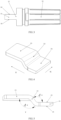
FIG. 2 is a structural schematic diagram illustrating an embodiment of a power transmission portion in the present invention. -
FIG. 3 is a structural schematic diagram illustrating another embodiment of a power transmission portion in the present invention. -
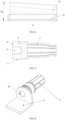
FIG. 4 is a structural schematic diagram illustrating an embodiment of a transfer portion in the present invention. -
FIG. 5 is a structural schematic diagram illustrating a Y direction inFIG. 4 in the present invention. -
FIG. 6 is a structural schematic diagram illustrating an X direction inFIG. 4 in the present invention. -
FIG. 7 is a structural schematic diagram illustrating another embodiment of the power transmission portion in the present invention. -
FIG. 8 is a structural schematic diagram illustrating an embodiment of a combination of the power transmission portion and the transfer portion in the present invention. -
FIG. 9 is a structural schematic diagram illustrating another embodiment of the combination of the power transmission portion and the transfer portion in the present invention. -
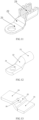
FIG. 10 is a structural schematic diagram illustrating a second end being bowl-shaped in the present invention. -
FIG. 11 is a structural schematic diagram illustrating the second end being U-shaped in the present invention. -
FIG. 12 is a structural schematic diagram illustrating the second end being barrel-shaped in the present invention. -
FIG. 13 is a structural schematic diagram illustrating a reinforcing rib provided at the transfer portion in the present invention. -
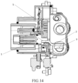
FIG. 14 is a structural schematic diagram illustrating a cross-section structure of a charging socket in the present invention. - 1-power transmission portion, 11-plug-in end, 12-connection end, 13-connecting surface, 14-first upper surface, 15-first side surface, 16-first lower surface, 17-side surface, 18-end surface, 19-threaded hole; 2-transfer portion, 21-first end, 22-bent portion, 23-second end, 24-second upper surface, 25-second side surface, 26-second lower surface, 27-through-hole, 28-reinforcing rib; 3-cable, 31-conductor, 32-insulation layer; 4-bolt; 5-charging socket.
- The present invention is described in further detail below, so that those skilled in the art can implement the present invention with reference to the disclosure contained in the specification. In order to have a clearer understanding of the technical features, objective and effects of the present invention, the embodiments of the present invention are currently described with reference to the drawings, among which, terms "first", "second" or the like are only used for descriptive purposes, and cannot be construed to indicate or imply relative importance or implicitly specify the number of indicated technical features. Therefore, the features limited by "first", "second" or the like may expressly or implicitly include one or more of such features. In the description of the present invention, unless otherwise specified, "a plurality of" means two or more. In the description of the present invention, unless otherwise specified, the term "connection" should be understood in a broad sense, for example, the connection may be a fixed connection, a detachable connection, a direct connection, or an indirect connection through an intermediate medium. Those skilled in the art can understand specific meanings of the terms in the present patent according to a specific situation.
- The present invention provides a transfer mechanism for power transmission, as illustrated in
FIG. 1 , comprising: apower transmission portion 1, atransfer portion 2 and acable 3, in which thepower transmission portion 1 comprises a plug-inend 11 and aconnection end 12 which are connected in sequence, thecable 3 comprises aninternal conductor 31 and aninsulation layer 32 wrapping theconductor 31, thetransfer portion 2 comprises afirst end 21, abent portion 22 and asecond end 23 which are connected in sequence, thefirst end 21 is electrically connected to theconnection end 12, thesecond end 23 is electrically connected to theconductor 31 on one end of thecable 3, and thebent portion 22 comprises at least one bent zone. - In the present invention, the
transfer portion 2 is used to connect thepower transmission portion 1 and theconductor 31 of thecable 3, respectively, and thebent portion 22 is disposed on thetransfer portion 2, thepower transmission portion 1 can be connected to thecable 3 in different axial directions, and thepower transmission portion 1 can be connected to thecable 3 at an angle, in order to reduce a size of an electric device mechanism, and the electric device mechanism can be adapted to more operational environments. - In addition, the present invention provides the
transfer portion 2, where an extended structure for connecting thecable 3 may not be provided on thepower transmission portion 1, the machining difficulty of shape complexity of thepower transmission portion 1 is also reduced while the material used in thepower transmission portion 1 is saved. Thepower transmission portion 1 can be mass-produced in a simple process, and the production efficiency of thepower transmission portion 1 is improved when machining hours are reduced. - In one embodiment, at least part of the
first end 21 is in contact connection with at least part of theconnection end 12. In order to realize the electrical connection between thepower transmission portion 1 and thetransfer portion 2, the connection end 12 of thepower transmission portion 1 needs to be electrically connected to thefirst end 21 of thetransfer portion 2, thus at least part of structure of thefirst end 21 is in contact connection with at least part of structure of theconnection end 12 to achieve the purpose of electrical connection between thepower transmission portion 1 and thetransfer portion 2. - In one embodiment, at least part of the
first end 21 is connected to at least part of theconnection end 12 by one or more methods including resistance welding, friction welding, ultrasonic welding, arc welding, laser welding, electron beam welding, pressure welding, diffusion welding, magnetic induction welding, screwing, clamping, splicing, and crimping. - The resistance welding refers to a method of welding by generating heat from a contact resistance by a high current passing through a contact point between an electrode and a workpiece. The friction welding refers to a method of welding by using heat generated by friction of a contact surface of a workpiece as a heat source, so that the workpiece is subjected to plastic deformation under pressure. The ultrasonic welding refers to rubbing surfaces of two objects against each other to form a fusion between molecular layers under pressure, by transmitting high-frequency vibration waves to surfaces of two objects to be welded. The arc welding refers to converting electrical energy into thermal energy and mechanical energy required for welding by using an arc as a heat source and using a physical phenomenon of air discharge to achieve the purpose of bonding metals. The main methods are SMAW, SAW, and GMAW. The laser welding refers to an efficient and precise welding method that uses a high-energy-density laser beam as a heat source. The electron beam welding refers to a welding method of bombarding a welding surface placed in vacuum or non-vacuum by using accelerated and focused electron beams to melt a workpiece to be welded. The pressure welding refers to a welding method of applying pressure to a weldment so that a joint surface is in close contact to produce a plastic deformation. The diffusion welding refers to a solid-state welding method in which a workpiece is pressurized at high temperature without visible deformation and relative movement. The magnetic induction welding refers to that two workpieces to be welded are subjected to an instantaneous high-speed collision under the action of a strong pulsed magnetic field, so that atoms of two materials on the material surface are met at an inter-atomic distance under the action of high pressure waves, in order to form a stable metallurgical bond on an interface, a solid-state cold welding, which can weld conductive metals with similar or dissimilar properties together. The screwing refers to a detachable connection in which a connected piece is integrated with a threaded piece (or a threaded part of the connected piece). Common threaded joints include: a
bolt 4, a stud, a screw and a set screw, mostly standard parts. The clamping refers to providing a claw or a groove on the connection end 12 or the connectingsurface 13, respectively, and assembling, by the claw and groove, to connect them together. The clamping has advantages of quick connection and detachability. The splicing refers to providing a groove and a protrusion on the connection end 12 or the connectingsurface 13, respectively, and assembling, by mortising or splicing, the groove and protrusion with each other to connect them together. The splicing has advantages of stable connection and detachability. The crimping refers to a production process in which theconnection end 12 and the connectingsurface 13 are assembled, and then stamped together by using a crimping machine. The crimping has an advantage of mass production. A large number of stable quality products can be quickly produced by using an automatic crimping machine. - In the connection methods, an appropriate connection method or a combination of connection methods can be selected according to actual operational environments and an actual state of the
connection end 12 and thefirst end 21, so that theconnection end 12 and thefirst end 21 are stably connected together to achieve an effective electrical connection. - In one embodiment, the
connection end 12 comprises the connectingsurface 13, and an area of a contact zone between the connectingsurface 13 and thefirst end 21 accounts for equal to or more than 5% of an area of the connectingsurface 13. In order to guarantee a good electrical connection between thepower transmission portion 1 and thetransfer portion 2, the contact area between the connectingsurface 13 and thefirst end 21 is a key characteristic. The larger the contact area, the lower the voltage drop between the connectingsurface 13 and thefirst end 21, the greater the pull-out force. In order to verify a ratio of the area of the contact zone between the connectingsurface 13 and thefirst end 21 to the area of the connectingsurface 13 and a relationship between the voltage drop between the connectingsurface 13 and thefirst end 21 and the pull-out force, the inventors selected ten sets of the samepower transmission portion 1 andtransfer portion 2, and provided the same connectingsurface 13 on thepower transmission portion 1, and then adopted the same ultrasonic welding method, but selected the ratio of the area of the contact zone between the connectingsurface 13 and thefirst end 21 to the area of the connectingsurface 13, and then tested the voltage drop between the connectingsurface 13 and thefirst end 21 by current conduction, and tested the pull-out force between the connectingsurface 13 and thefirst end 21. The results are recorded in Table 1. - A method of testing a voltage drop refers to placing the
connection end 12 and thefirst end 21 on a voltage drop detection table, testing voltage values A and B of the connectingsurface 13 and thefirst end 21 themselves, respectively, and then testing a voltage value C of the connectingsurface 13 to thefirst end 21, and then calculating a value of C-(A+B) as a voltage drop value of a connection point between the connectingsurface 13 and thefirst terminal 21. In this embodiment, a voltage drop value greater than 4 mV is unqualified. - A method for testing a pull-out force refers to using a pull-out force tester to fix the
connection end 12 and thefirst end 21 welded on fixtures of the pull-out force tester on both ends, respectively, and then starting up the pull-out force tester so that the fixtures on both ends move in two opposite directions at a uniform speed, and recording the pull-out force when thefirst end 21 is detached from theconnection end 12. In this embodiment, a pull-out force less than 1600 N is unqualified.Table 1: Effects of the ratio of the area of the contact zone between the connecting surface 13 and thefirst end 21 to the area of the connectingsurface 13 on the voltage drop and pull-out forcethe ratio of the area of the contact zone between the connecting surface 13 and thefirst end 21 to the area of the connecting surface 13 (%)1 3 5 10 15 20 40 60 80 100 the voltage drop between the connecting surface 13 and the first end 21 (mV)4.82 4.36 3.85 3.58 3.16 2.84 2.58 2.17 1.77 1.35 the pull-out force between the connection end 12 and the first end 21 (N)1508 1587 1623 1694 1763 1827 1886 1935 1994 2062 - It can be seen from the Table 1 that when the area of the contact zone between the connecting
surface 13 and thefirst end 21 accounts for less than 5% of the area of the connectingsurface 13, the voltage drop between the connectingsurface 13 and thefirst end 21 is greater than 4 mV, and the pull-out force between the connectingsurface 13 and thefirst end 21 is less than 1600 N, both of which are unqualified; and when the area of the contact zone between the connectingsurface 13 and thefirst end 21 accounts for equal to or more than 5% of the area of the connectingsurface 13, the voltage drop between the connectingsurface 13 and thefirst end 21 and the pull-out force are better than qualified values, and the greater the ratio, the better the electrical and mechanical performance of the connectingsurface 13 and thefirst end 21. Therefore, the inventors set that the area of the contact zone between the connectingsurface 13 and thefirst end 21 accounts for equal to or more than 5% of the area of the connectingsurface 13. - In one embodiment, as illustrated in
FIGS. 2-6 , theconnection end 12 is sheet-shaped, theconnection end 12 comprises a firstupper surface 14, a firstlower surface 16 and afirst side surface 15, and the connectingsurface 13 is arranged on the firstupper surface 14 or the firstlower surface 16, thefirst end 21 is sheet-shaped and comprises a secondupper surface 24, a secondlower surface 26 and asecond side surface 25, and the firstupper surface 14 or the firstlower surface 16 is overlapped and then in contact with the secondupper surface 24 or the secondlower surface 26. Both theconnection end 12 and thefirst end 21 are sheet-shaped, are easy to machine, and are also easy to overlap and connect, which is beneficial to the manufacture of equipment fixtures and welding molds, and facilitates automatic production, improves production efficiency, and reduces production costs. - In one embodiment, as illustrated in
FIGS. 7-9 , theconnection end 12 is column-shaped and comprises aside surface 17 and anend surface 18, the connectingsurface 13 is disposed on theend surface 18, and thefirst end 21 is sheet-shaped and comprises a secondupper surface 24, a secondlower surface 26 and asecond side surface 25, and theend surface 18 is in contact connection with the secondupper surface 24 or the secondlower surface 26. The end of thepower transmission portion 1 is not machined into a sheet-like structure, but directly machined into theend surface 18, which can reduce the machining steps, reduce the machining time, and can shorten the length of thepower transmission portion 1, simplify the size of the transfer mechanism for power transmission. In addition, the machining material of thepower transmission portion 1 can be saved, and the cost of thepower transmission portion 1 can be reduced. Theend surface 18 of theconnection end 12 and thefirst end 21 can be connected together by welding, screwing, clamping or splicing. - In one embodiment, as illustrated in
FIGS. 7-9 , the transfer mechanism for power transmission further comprises abolt 4, the secondupper surface 24 is provided with a through-hole 27 penetrating to the secondlower surface 26, and theend surface 18 is provided with a threadedhole 19, and thebolt 4 is screwed with the threadedhole 19 through the through-hole 27. Thepower transmission portion 1 and thetransfer portion 2 can be quickly connected together by means of threaded connection, and can be detachable, and can be easily disassembled and replaced in subsequent maintenance and repairs. - In one embodiment, a torque of the screwing between the
bolt 4 and the threadedhole 19 is in a range of 0.1 N·m to 30 N·m. - In order to verify the range of the torque of the screwing between the
bolt 4 and the threadedhole 19 and the effects on the electrical connection and mechanical connection performance of thepower transmission portion 1 and thetransfer portion 2, the inventors selected the samepower transmission portion 1,transfer portion 2,bolt 4 and the threadedhole 19, tightened them together with different torques, tested the contact resistance between thebolt 4 and the threadedhole 19 and the connection between thebolt 4 and the threadedhole 19 after the vibration test, respectively. The test results are shown in Table 2. - A method of testing the contact resistance between the
bolt 4 and the threadedhole 19 refers to using a micro-resistance meter, placing one end such as a measuring end of the micro-resistance meter on thepower transmission portion 1, and placing the other end on thetransfer portion 2, measuring in the same position each time, then reading a contact resistance reading on the micro-resistance meter. In this embodiment, a contact resistance greater than 1 mQ is unqualified. - A vibration test refers to placing a connected sample on a vibration test table, after 300 vibration cycles, each cycle requiring vibration in six directions at frequency of 100 Hz, at acceleration in one direction of 40 m/s2, then observing whether the
bolt 4 is loose from the threadedhole 19. In this embodiment, the looseness of thebolt 4 from the threadedhole 19 is unqualified.Table 2: Effects of different torques of the bolt 4 and the threadedhole 19 on the electrical connection and mechanical connection performance of thepower transmission portion 1 and thetransfer portion 2the torque of the bolt 4 and the threaded hole 19 (N·m)0.01 0.05 0.1 0.5 1 3 5 10 15 20 25 30 32 35 the contact resistance between the power transmission portion 1 and the transfer portion 2 (mΩ)1.16 1.05 0.96 0.94 0.91 0.88 0.86 0.83 0.81 0.79 0.74 0.71 0.71 0.7 1 the connection between the power transmission portion 1 and thetransfer portion 2loose loose not loose not loose not loose not loose not loose not loose not loose not loose not loose not loose not loose not loose - It can be seen from the Table 2 that when the torque value of the screwing between the
bolt 4 and the threadedhole 19 is less than 0.1 N·m, the contact resistance value between thepower transmission portion 1 and thetransfer portion 2 is unqualified, and thepower transmission portion 1 is loose from thetransfer portion 2 after the vibration test, therefore, the inventors set a minimum value of range of the torque of the screwing between thebolt 4 and the threadedhole 19 to be 0.1 N·m. When the torque value of the screwing between thebolt 4 and the threadedhole 19 is more than 30N·m, the contact resistance between thepower transmission portion 1 and thetransfer portion 2 cannot be further reduced. Therefore, the inventors determined the torque of the screwing between thebolt 4 and the threadedhole 19 to be in a range of 0.1 N·m to 30 N·m. - In one embodiment, the
connection end 12 is barrel-shaped and comprises a first inner surface and a first outer surface, the connectingsurface 13 is arranged on the first inner surface or the first outer surface, and thefirst end 21 is barrel-shaped and comprises a second inner surface and a second outer surface, and the first inner surface or the first outer surface is overlapped and then in contact with the second outer surface or the second inner surface. Both theconnection end 12 and thefirst end 21 are barrel-shaped, and can be overlapped together by socketing, and then connected in the above connection method. This overlapping socketing method achieves a large contact area between theconnection end 12 and thefirst end 21, thus the contact resistance between theconnection end 12 and thefirst end 21 can be effectively reduced and the electrical performance of the transfer mechanism for power transmission can be improved. - In one embodiment, a cross-section of the connection end 12 or the
first end 21 is circular, elliptical, rectangular or polygonal. Theconnection end 12 or thefirst end 21 has a barrel-shaped structure, the cross-section may be set in a plurality of shapes, and different cross-sectional shapes may be selected according to a specific operational environment of the connection end 12 or thefirst end 21 and an own machining technology thereof, so as to achieve the purpose of effectively electrically connecting theconnection end 12 to thefirst end 21. - In one embodiment, as illustrated in
FIGS. 10-12 , thesecond end 23 is tabular, bowl-shaped, U-shaped, V-shaped or barrel-shaped. Thesecond end 23 is in a position where thetransfer portion 2 is connected to theconductor 31 of thecable 3, and the shape of thesecond end 23 may be selected according to the shape of theconductor 31 of thecable 3 and the specific operational environment. The shape such as the tabular shape and bowl-shape are generally used for welding with theconductor 31, the U-shape and V-shape are generally used for crimping with theconductor 31, and the barrel-shape can be used for crimping or welding with theconductor 31. - In one embodiment, at least part of the
conductor 31 is in contact connection with at least part of thesecond end 23. In order to realize the electrical connection between thetransfer portion 2 and theconductor 31 of thecable 3, theconductor 31 of thecable 3 needs to be electrically connected to thesecond end 23 of thetransfer portion 2, and at least part of structure of theconductor 31 of thecable 3 is in contact connection with at least part of structure of thesecond end 23, so as to achieve the purpose of electrically connecting thetransfer portion 2 to theconductor 31 of thecable 3. - In one embodiment, at least part of the
conductor 31 is connected to at least part of thesecond end 23 by one or more methods including resistance welding, friction welding, ultrasonic welding, arc welding, laser welding, electron beam welding, pressure diffusion welding, magnetic induction welding, screwing, clamping, splicing, and crimping. - The specific connection methods have been described in detail in the description, and will not be described here anymore. In the above connection methods, an appropriate connection method or a combination of the connection methods can be selected, according to the actual operational environment, and the actual state of the
conductor 31 of thecable 3 and thesecond end 23, and at least part of theconductor 31 of thecable 3 is stably connected to at least part of thesecond end 23 to realize an effective electrical connection. - In one embodiment, the
connection end 12 comprises the connectingsurface 13, at least part of thefirst end 21 is at least partially in contact connection with the connectingsurface 13; thesecond end 23 comprises a wiring surface, and the area of the contact zone between the wiring surface and theconductor 31 accounts for equal to or more than 5% of the area of the wiring surface. In order to guarantee a good electrical connection between thetransfer portion 2 and theconductor 31 of thecable 3, the contact area between the wiring surface and theconductor 31 is a key characteristic. The larger the contact area, the lower the voltage drop between the wiring surface and theconductor 31, the greater the pull-out force. In order to verify a ratio of the area of the contact zone between the wiring surface and theconductor 31 to the area of the wiring surface, and a relationship between the voltage drop between the wiring surface and theconductor 31 and the pull-out force, the inventors selected ten sets of thesame transfer portion 2 andcable 3, and provided the same wiring surface on thesecond end 23, then adopted the same ultrasonic welding method, but selected a ratio of the area of the different contact zone between the wiring surface and theconductor 31 to the area of the wiring surface, and then tested the voltage drop between the wiring surface and theconductor 31 by current conduction, and tested the pull-out force between the wiring surface and theconductor 31. The results are recorded in Table 3. - A method of testing a voltage drop refers to placing the
transfer portion 2 and thecable 3 on a voltage drop detection table, testing voltage values A and B of the wiring surface and theconductor 31 themselves, respectively, then testing a voltage value C of the wiring surface to theconductor 31, and then calculating a value of C-(A+B) as a voltage drop value of a connection point between the wiring surface and theconductor 31. In this embodiment, a voltage drop value greater than 4mV is unqualified. - A method of testing a pull-out force refers to using a pull-out force tester to fix the wiring surface and the
conductor 31 welded on fixtures of the pull-out force tester on both ends, respectively, and then starting up the pull-out force tester so that the fixtures on both ends move in two opposite directions at a uniform speed, and recording the pull-out force when theconductor 31 is detached from the wiring surface. In this embodiment, a pull-out force less than 1600 N is unqualified.Table 3: Effects of the ratio of the area of the contact zone between the wiring surface and the conductor 31 to the area of the wiring surface on the voltage drop and the pull-out force between the wiring surface and theconductor 31the ratio of the area of the contact zone between the wiring surface and the conductor 31 to the area of the wiring surface (%)1 3 5 10 15 20 40 60 80 100 the voltage drop between the wiring surface and the conductor 31 (mV) 4.93 4.27 3.92 3.66 3.24 2.73 2.62 2.21 1.69 1.43 the pull-out force between the wiring surface and the conductor 31 (N) 1442 1578 1625 1683 1777 1835 1879 1933 1991 2054 - It can be seen from the Table 3 that when the ratio of the area of the contact zone between the wiring surface and the
conductor 31 accounts for less than 5% of the area of the wiring surface, the voltage drop between the wiring surface and theconductor 31 is greater than 4 mV, and the pull-out force between the wiring surface and theconductor 31 are less than 1600 N, both of which are unqualified; and when the area of the contact zone between the wiring surface and theconductor 31 accounts for equal to or more than 5% of the area of the wiring surface, the voltage drop and the pull-out force between the wiring surface and theconductor 31 are better than qualified values, and the greater the ratio, the better the electrical performance and mechanical performance of the wiring surface and theconductor 31. Therefore, the inventors set that the contact area between the wiring surface and theconductor 31 accounted for equal to or more than 5% of the area of the wiring surface. - In one embodiment, the
transfer portion 2 is formed by stamping, cutting, bending or machining a plate. Plate machining process is a simple and mature process in the current metal machining technology, and plate is also one of the materials easily obtained. If the shape of thetransfer portion 2 is not complicated, the waste generated in the plate machining process is much less than that generated in machining processes such as turning, milling, or the like, and is one of the production processes with high material utilization. The formedtransfer portion 2 can be quickly produced in mass by using the mature plate stamping process and stamping dies. In addition, advanced processing techniques such as laser cutting and waterjet cutting can also be adopted to first blank the plate, and then the bending process can be adopted for forming, or machining the plate in the machined form can also reduce the production costs and improve the production efficiency of thetransfer portion 2. - In one embodiment, the
first end 21, thebent portion 22 and thesecond end 23 each have a thickness that differs by no more than 35%. For thetransfer portion 2 to be formed of a plate, it is optimal that the plate has a consistent thickness, and the material is common, and when stamping or cutting and bending are adopted, the machining parameters can also be stable, however, due to various shapes of the connection end 12 or theconductor 31, the transfer mechanism for power transmission is also involved in various spaces and use environments. In some cases, thefirst end 21, thebent portion 22 and thesecond end 23 of different widths need to be used. In order to ensure the consistent conduction current of thetransfer portion 2, the cross-sectional area of thetransfer portion 2 at each position cannot differ too much, thus thefirst end 21, thebent portion 22 and thesecond end 23 having different thicknesses need to be used. - In order to verify the percentage of difference in thickness among the
first end 21, thebent portion 22, and thesecond end 23 and the effects of the voltage drop on thetransfer portion 2 itself, the inventors selected a plurality of samples of thetransfer portion 2 having the same length, width and shape as thebent portion 22, and having different thicknesses from thefirst end 21, thebent portion 22 and thesecond end 23, and tested the voltage drop on both ends of thetransfer portion 2. The test results are recorded in Table 4. In this embodiment, a voltage drop value greater than 4 mV is unqualified. - It should be noted that a percentage of difference in thickness among the
first end 21, thebent portion 22 and thesecond end 23 refers to a value of maximum thickness/minimum thickness among thefirst end 21, thebent portion 22 and the second end 23 x 100%. - A method of testing a voltage drop refers to using a sample of the
transfer portion 2 of which a thickness is the same as a minimum thickness of a sample piece, and other size and shape are the same, testing a voltage value D on both ends on a voltage drop detection table, and then using a sample of thetransfer portion 2 having a different thickness from that in this embodiment, testing a voltage value E on both ends at the same position, and then calculating values of E-D as a voltage drop value of thetransfer portion 2.Table 4: Effects of the percentage of difference in thickness on the voltage drop of the transfer portion 2the percentage of difference in thickness of the first end 21, thebent portion 22 and the second end 23 (%)5 10 15 25 35 40 50 60 70 80 90 100 the voltage drop of the transfer portion 2 (mV) 2.64 3.05 3.37 3.61 3.95 4.11 4.53 5.04 5.67 6.13 6.58 7.21 - It can be seen from the Table 4 that when the percentage of difference in thickness among the
first end 21, thebent portion 22 and thesecond end 23 is greater than 35%, the voltage drop value of thetransfer portion 2 does not meet the requirements of the qualified value due to significant differences in cross-sectional areas of the portions, when thefirst end 21, thebent portion 22 and thesecond end 23 each have a thickness that differs by no more than 35%, the voltage drop value of thetransfer portion 2 is qualified. Therefore, the inventors set that thefirst end 21, thebent portion 22 and thesecond end 23 each have a thickness that differs by no more than 35%. - In one embodiment, an included angle between two adjacent planes in the bent zone is 0° to 180°. A bending angle falls within a range of 0° to 180° to readily meet the requirements of different wiring directions of the
transfer portion 2. As illustrated inFIG. 5 , thetransfer portion 2 has two bent zones with a bending angle opposite A°, so that thefirst end 21 and thesecond end 23 of thetransfer portion 2 form two substantially parallel planes. As illustrated inFIG. 8 , thetransfer portion 2 has a bent zone with a bending angle 90°, the outgoing direction of thecable 3 may be 90° to the axial direction of thepower transmission portion 1, in order to meet the requirements for outgoing in different directions. In the other embodiments, the included angle between two adjacent planes in the bent zone may be changed due to a space limitation of the transfer mechanism for power transmission or other requirements of outgoing directions. - In one embodiment, a bend of the bent zone is arc-shaped, and an inner radius of the bent is not less than one-third of a thickness of the
transfer portion 2. It should be noted that the bend of the bent zone is generally bent by stamping or using a bending machine. If the inner radius of the bent zone is too small or even zero, an external radius at the bend is also small, thereby resulting in excessive external stretching at the bend and concentrated stress at the bend. In the subsequent use process, thecable 3 may transmit the external shaking to the bent zone of thetransfer portion 2. If the concentrated stress at the bend may cause the bend to fracture due to shaking, so that malfunctioning of the transfer mechanism for power transmission occurs, and in severe cases, a short circuit or a burning accident occurs. Therefore, in order to disperse the stress at the bend, the inner radius of the bend in the bent zone is greater than or equal to one-third of the thickness of thetransfer portion 2. - In one embodiment, at least one reinforcing
rib 28 is disposed in a tangential direction of the bent zone, and the reinforcingrib 28 is formed by inward depressing a material outside the bent zone. As illustrated inFIG. 13 , stamping is used in the bent zone, and at least one reinforcingrib 28 is machined, thus the strength of the bent zone can be strengthened, the maximum force that thetransfer portion 2 can withstand in the bent zone can be increased, and the sheet-shapedtransfer portion 2 can have a longer service life. - In one embodiment, the bent zone is twisted, and an included angle between a plane or a longitudinal center symmetry plane of the
first end 21 and a plane or a longitudinal center symmetry plane of thesecond end 23 is 0° to 90°. When the outgoing direction of thecable 3 is at a special angle for thetransfer portion 2, the bent zone needs to be twisted when the angle formed by simply bending the bent zone is not satisfactory, so that the plane of thefirst end 21 is no longer parallel to but at an angle to the plane of thesecond end 23. When thefirst end 21 and thesecond end 23 are not planes, the longitudinal center symmetry plane of thefirst end 21 or thesecond end 23 may serve as a reference plane. At this time, the outgoing angle of thecable 3 is at an angle to an axial direction and a radial direction of thepower transmission portion 1. As illustrated inFIG. 6 , an included angle between the plane of thefirst end 21 and the plane of thesecond end 23 is B°. - In one embodiment, a material of the
transfer portion 2 comprises one or more of nickel, cadmium, zirconium, chromium, cobalt, manganese, aluminum, tin, titanium, zinc, copper, silver, gold, phosphorus, tellurium, beryllium, and lead. - In order to demonstrate the effects of different materials of the
transfer portion 2 on electrical conductivity of thetransfer portion 2, the inventors produced samples of thetransfer portion 2 by using different materials with the same size, and tested the electrical conductivity of thetransfer portion 2, respectively. The results are shown in Table 5. In this embodiment, it is ideal that the electrical conductivity of thetransfer portion 2 is greater than 99%.Table 5: Effects of different materials of the transfer portion 2 on the electrical conductivity of thetransfer portion 2different materials of the transfer portion 2nick el Ca dm iu m zirco niu m chro miu m cob alt ma nga nes e alum inu m tin tita niu m zin c cop per silv er gol d tell uri um ber ylli um lea d the electrical conductivity of the transfer portion 2 (%) 99.4 99. 3 99.2 99.2 99. 3 99. 3 99.6 99. 5 99. 5 99. 3 99. 7 99. 9 99. 7 99. 3 99. 4 99. 2 - It can be seen from the Table 5 that the electrical conductivity of the
transfer portion 2 made of the selected metal materials falls within a range of ideal values. In addition, phosphorus is a non-metallic material and cannot be directly used as a material of thetransfer portion 2, but can be added to other metals to form an alloy, in order to improve the electrical conductivity and mechanical performance of the metal itself. Therefore, the inventors set that the material of thetransfer portion 2 comprises one or more of nickel, cadmium, zirconium, chromium, cobalt, manganese, aluminum, tin, titanium, zinc, copper, silver, gold, phosphorus, tellurium, beryllium, and lead. - In one embodiment, a material of the
transfer portion 2 comprises a tellurium-copper alloy, in which the content of tellurium is 0.1% to 5%. Thetransfer portion 2 has good electrical conductivity and processibility, ensures electrical performance, and can also improve machinability. - In order to verify the effects of the content of tellurium in the tellurium-copper alloy in the material of the
transfer portion 2 on the electrical conductivity of thetransfer portion 2, the inventors selected and tested tentransfer portions 2 having the same shape, and each of thetransfer portions 2 has the same size, thetransfer portion 2 is made of a tellurium-copper alloy, in which the content of tellurium is 0.05%, 0.1%, 0.2%, 0.5%, 0.8%, 1.2%, 2%, 3%, 5%, 6%, 7%, respectively. A current is conducted through thetransfer portion 2, and the electrical conductivity of thetransfer portion 2 is detected accordingly. The test results are shown in Table 6. In this embodiment, it is ideal that the electrical conductivity is greater than 99%.Table 6: Effects of the tellurium-copper alloy with different tellurium contents on the electrical conductivity of the transfer portion 2the tellurium-copper alloy with different tellurium contents (%) 0.05 0.1 0.2 0.5 0.8 1.2 2 3 5 6 7 the electrical conductivity of the transfer portion 2 (%) 98.4 99.2 99.6 99.7 99.8 99.7 99.5 99.5 99.1 98.9 98.6 - It can be seen from the Table 6 that when the content of tellurium is less than 0.1% or greater than 5%, the electrical conductivity significantly decreases, and cannot meet the requirements of the ideal electrical conductivity; when the content of tellurium is greater than or equal to 0.2% and less than or equal to 1.2%, the optimal electrical conductivity is achieved; when the content of tellurium is greater than or equal to 0.1% and less than 0.2%, or greater than 1.2% and less than or equal to 5%, although the electrical conductivity meets the requirements of the ideal electrical conductivity, the trend is a gradual decline and the electrical conductivity also decreases. Therefore, the inventors chose a tellurium-copper alloy having a tellurium content of 0.1% to 5%. In the most ideal situation, a tellurium-copper alloy having a tellurium content of 0.2% to 1.2% is chosen.
- In one embodiment, the material of the
transfer portion 2 comprises a beryllium copper alloy, in which the content of beryllium is 0.05% to 5%. Preferably, the content of beryllium in the material of thetransfer portion 2 is 0.1% to 3.5%. - The beryllium contained in the
transfer portion 2 enables thetransfer portion 2 to have high hardness, elastic limit, fatigue limit, and wear resistance, and also have good corrosion resistance, thermal conductivity and electrical conductivity, and does not generate any spark when impacted. - In order to test the effects of the content of beryllium on the electrical conductivity of the
transfer portion 2, the inventors selected and tested tentransfer portions 2 having the same shape and width. Each of thetransfer portions 2 contains beryllium, in which the proportion of beryllium content is 0.03%, 0.05%, 0.1%, 0.2%, 1%, 1.8%, 3%, 3.5%, 5%, 6%, respectively. The test results are shown in Table 7. In this embodiment, it is ideal that the electrical conductivity is greater than 99%.Table 7: Effects of different beryllium contents on electrical conductivity the tellurium-copper alloy with different beryllium contents (%) 0.03 0.05 0.1 0.2 1 1.8 3 3.5 5 6 the electrical conductivity of the transfer portion 2 (%) 98.9 99.2 99.5 99.6 99.8 99.6 99.3 99.2 99.1 98.7 - It can be seen from the Table 7 that when the content of beryllium is less than 0.05% or greater than 5%, the electrical conductivity decreases significantly and cannot meet actual needs; when the content of beryllium is greater than or equal to 0.1% and less than or equal to 3.5%, the optimal electrical conductivity is achieved, thus the inventors chose the
transfer portion 2, in which the content of beryllium is 0.05% to 5%. In the most ideal situation, thetransfer portion 2, in which the content of beryllium is 0.1% to 3.5%, is selected. - In one embodiment, the material of the
transfer portion 2 comprises a phosphor bronze alloy, in which the content of phosphorus is 0.01% to 1.5%. An advantage of phosphor bronze is that phosphor bronze has better corrosion resistance and wear resistance to guarantee good contact and elasticity of thetransfer portion 2, and has excellent machining performance, thus the machining time of parts can be quickly shortened. - In order to test the effects of phosphorus content on the electrical conductivity of the
transfer portion 2, the inventors selected and tested tentransfer portions 2 having the same shape and width. Each of thetransfer portion 2 contains phosphorus, in which the proportion of phosphorus content is 0.001%, 0.005%, 0.01%, 0.05%, 0.1%, 0.5%, 1%, 1.5%, 2%, 2.5%, respectively. The test results are shown in Table 8. In this embodiment, it is ideal that the electrical conductivity is greater than 99%.Table 8: Effects of different phosphorus contents on electrical conductivity the phosphor bronze alloy having different phosphorus contents (%) 0.001 0.005 0.01 0.05 0.1 0.5 1 1.5 2 2.5 the electrical conductivity of the transfer portion 2 (%) 98.6 98.9 99.2 99.6 99.8 99.6 99.3 99.2 98.8 98.3 - It can be seen from the Table 8 that when the content of phosphorus is less than 0.01% or greater than 1.5%, the electrical conductivity decreases significantly, and cannot meet actual needs; when the content of phosphorus is greater than or equal to 0.05% and less than or equal to 0.5%, the optimal electrical conductivity is achieved, thus the inventors chose the
transfer portion 2, in which the content of phosphorus is 0.01% to 1.5%. In the most ideal situation, thetransfer portion 2, in which the content of phosphorus is 0.05% to 0.5%, is selected. - In one embodiment, the material of the
transfer portion 2 comprises a lead brass alloy, in which the content of lead is 0.1% to 5%. Advantages of the lead brass alloy are high strength, dense and uniform structure, good corrosion resistance, and excellent machining performance such as cutting and drilling. - In order to test the effects of lead content on the electrical conductivity of the
transfer portion 2, the inventors selected and tested tentransfer portions 2 having the same shape and width. Each of thetransfer portions 2 contains lead, in which the proportion of lead content is 0.05%, 0.1%, 0.5%, 1%, 2%, 3%, 4%, 5%, 6%, 7%, respectively. The test results are shown in Table 9. In this embodiment, it is ideal that the electrical conductivity is greater than 99%.Table 9: Effects of different lead contents on electrical conductivity the lead brass alloy having different lead contents (%) 0.05 0.1 0.5 1 2 3 4 5 6 7 the electrical conductivity of the transfer portion 2 (%) 98.6 99.2 99.3 99.6 99.8 99.6 99.3 99.1 98.8 98.3 - It can be seen from the Table 9 that when the content of lead is less than 0.1% or greater than 5%, the electrical conductivity decreases significantly and cannot meet actual needs; when the content of lead is greater than or equal to 1% and less than or equal to 3%, the optimal electrical conductivity is achieved, thus the inventors chose the
transfer portion 2, in which the content of lead is 0.1%-5%. In the most ideal situation, thetransfer portion 2, in which the content of lead is 1% to 3%, is selected. - In one embodiment, the
power transmission portion 1, theconductor 31 and thetransfer portion 2 are at least partially provided with a coating to improve the corrosion resistance of thepower transmission portion 1, theconductor 31 and thetransfer portion 2 and improve the electrical conductivity, which can thus better prolong the service life of the transfer mechanism for power transmission. - In one embodiment, at least part of the connecting
surface 13 is not provided with a coating. When thepower transmission portion 1 is connected to thetransfer portion 2, and when the connecting surface is connected by welding or pressing, the method of providing no coating may be adopted, so that the two connecting surfaces are in direct contact, which can thus reduce the contact resistance and reduce the voltage drop between thepower transmission portion 1 and thetransfer portion 2 and improve the electrical performance of the transfer mechanism for power transmission. - In one embodiment, at least part of the connecting
surface 13 is provided with a coating as a first coating. When the transfer mechanism for power transmission is in a harsh environment, a coating is required to improve corrosion resistance; or thepower transmission portion 1 and thetransfer portion 2 are made of different materials, and a plated metal is required for transition. At this time, a coating needs to be provided on the connectingsurface 13, and in order to distinguish such a coating from other coatings, the coating on the connectingsurface 13 is the first coating. - In one embodiment, a plane of the
first end 21 at least in contact with the connectingsurface 13 is not provided with the coating. Similarly, when thepower transmission portion 1 is connected to thetransfer portion 2, and when the connecting surface is connected by welding or pressing, the method of providing no coating may be adopted, so that the two connecting surfaces are in direct contact, which can thus reduce the contact resistance and reduce the voltage drop between thepower transmission portion 1 and thetransfer portion 2 and improve the electrical performance of the transfer mechanism for power transmission. - In one embodiment, the
first end 21 is provided with a coating on a plane at least in contact with the connectingsurface 13, and the coating of thefirst end 21 on a plane at least in contact with the connectingsurface 13 is the second coating. When the transfer mechanism for power transmission is in a harsh environment, a coating is required to improve corrosion resistance; or thepower transmission portion 1 and thetransfer portion 2 are made of different materials, and a plated metal is required for transition. At this time, a coating needs to be provided on thefirst end 21, and in order to distinguish such a coating from other coatings, the coating on thefirst end 21 is the second coating. - In one embodiment, at least part of the wiring surface is not provided with a coating. Similarly, when the
conductor 31 is connected to thetransfer portion 2, and when the wiring surface is connected by welding or pressing, the method of providing no coating can be adopted, so that the two surfaces are in direct contact, which can thus reduce the contact resistance and reduce the voltage drop between theconductor 31 and thetransfer portion 2 and improve the electrical performance of the transfer mechanism for power transmission. - In one embodiment, at least part of the wiring surface is provided with a coating as the third coating. When the transfer mechanism for power transmission is in a harsh environment, a coating is required to improve corrosion resistance. At this time, a coating needs to be provided on the
transfer portion 2. In order to distinguish such a coating from other coatings, the coating on the wiring surface is the third coating. - In one embodiment, no coating is provided on the
conductor 31. Similarly, when theconductor 31 is connected to thetransfer portion 2, and when the connecting surface is connected by welding or pressing, the method of providing no coating may be adopted, so that the two connecting surfaces are in direct contact, which can thus reduce the contact resistance and reduce the voltage drop between theconductor 31 and thetransfer portion 2 and improve the electrical performance of the transfer mechanism for power transmission. - In one embodiment, at least part of the
conductor 31 is provided with the coating as a fourth coating. When the transfer mechanism for power transmission is in a harsh environment, a coating is required to improve the corrosion resistance of theconductor 31. At this time, a coating needs to be provided on theconductor 31. In order to distinguish such a coating from other coatings, the coating on theconductor 31 is the fourth coating. - In one embodiment, the first coating, the second coating, the third coating and the fourth coating are made of different materials. That is, at least one of the first coating, the second coating, the third coating and the fourth coating is different in material from the others, i.e., the first coating material may be different from the second coating material, the third coating material and the fourth coating material; or the second coating material may be different from the first coating material, the third coating material and the fourth coating material; or the third coating material may be different from the first coating material, the second coating material and the fourth coating material; or the fourth coating material may be different from the first coating material, the second coating material and the third coating material.
- Alternatively, two of the first coating, the second coating, the third coating and the fourth coating are the same in material, but different from the other two, i.e., the material of the first coating may be the same as that of the second coating, the material of the third coating may be the same as that of the fourth coating, however, the material of the first coating may be different from that of the third coating; or the material of the first coating may be the same as that of the third coating, and the material of the second coating may be the same as that of the fourth coating, however, the material of the first coating may be different from that of the second coating; or the material of the first coating may be the same as that of the fourth coating, and the material of the second coating may be the same as that of the third coating, however, the material of the first coating may be different from that of the second coating,
- Alternatively, three of the first coating, the second coating, the third coating and the fourth coating are different in material, i.e., the material of the first coating may be the same as that of the second coating, but different from the materials of the third coating and the fourth coating; the material of the first coating may be the same as that of the third coating, but different from the materials of the second coating and the fourth coating; the material of the first coating may be the same as that of the fourth coating, but different from the materials of the second coating and the third coating; the material of the second coating may be the same as that of the third coating, but different from the materials of the first coating and the fourth coating; the material of the second coating may be the same as that of the fourth coating, but different from the materials of the first coating and the third coating; and the material of the third coating may be the same as that of the fourth coating, but different from the materials of the first coating and the second coating.
- In one embodiment, the thickness of the first coating, the thickness of the second coating, the thickness of the third coating are different from that of the fourth coating. That is, at least one of the first coating, the second coating, the third coating and the fourth coating has a thickness different from the others, i.e., the thickness of the first coating may be different from the thickness of the second coating, the thickness of the third coating and the thickness of the third coating; or the thickness of the second coating may be different from the thickness of the first coating, the thickness of the third coating and the thickness of the fourth coating; or the thickness of the third coating may be different from the thickness of the first coating, the thickness of the second coating and the thickness of the fourth coating; or the thickness of the fourth coating may be different from the thickness of the first coating, the thickness of the second coating and the thickness of the third coating.
- Alternatively, two of the first coating, the second coating, the third coating and the fourth coating are the same in thickness, but different from the other two, i.e., the thickness of the first coating may be the same as the thickness of the second coating, the thickness of the third coating may be the same as the thickness of the fourth coating, however, the thickness of the first coating may be different from the thickness of the third coating; or the thickness of the first coating may be the same as the thickness of the third coating, the thickness of the second coating may be the same as the thickness of the fourth coating, however, the thickness of the first coating may be different from the thickness of the second coating; or the thickness of the first coating may be the same as the thickness of the fourth coating, the thickness of the second coating may be the same as the thickness of the third coating, however, the thickness of the first coating may be different from the thickness of the second coating,
- Alternatively, three of the first coating, the second coating, the third coating and the fourth coating are different in thickness, i.e., the thickness of the first coating may be the same as the thickness of the second coating, but different from the thickness of the third coating and the thickness of the fourth coating; the thickness of the first coating may be the same as the thickness of the third coating, but different from the thickness of the thickness of the second coating and the thickness of the fourth coating; the thickness of the first coating may be the same as the thickness of the fourth coating, but different from the thickness of the second coating and the thickness of the third coating; the thickness of the second coating may be the same as the thickness of the third coating, but different from the thickness of the first coating and the thickness of the fourth coating; the thickness of the second coating may be the same as the thickness of the fourth coating, but different from the thickness of the first coating and the thickness of the third coating; and the thickness of the third coating may be the same as the thickness of the fourth coating, but different from the thickness of the first coating and the thickness of the second coating.
- In one embodiment, a material of the coating comprises one or more of gold, silver, nickel, tin, zinc, a tin-lead alloy, a silver-antimony alloy, palladium, a palladium-nickel alloy, graphite silver, graphene silver, and a silver-gold-zirconium alloy. In most cases, the
power transmission portion 1 and thetransfer portion 2 may be made of a copper material. As an active metal, copper oxidizes with oxygen and water in use, thus one or more inactive metals are required as a coating to prolong the service life of thepower transmission portion 1 and thetransfer portion 2. The conductivity and stability of the metals are better than those of copper or copper alloys, thus thepower transmission portion 1 and thetransfer portion 2 can obtain better electrical performance and longer service life. - In order to demonstrate the effects of different coating materials on the overall performance of the
power transmission portion 1 and thetransfer portion 2, the inventors used samples of thepower transmission portion 1 and thetransfer portion 2 having the same specification and materials but different coating materials and performed a series of corrosion-resistant time tests. The experimental results are shown in Table 10. - The corrosion-resistant time tests in the Table 10 are that samples of the
power transmission portion 1 and thetransfer portion 2 are placed in a salt-spraying test chamber, and salt is sprayed at each position of the samples of thepower transmission portion 1 and thetransfer portion 2, removed and cleaned every 20 hours to observe the surface corrosion, that is, one cycle, until a surface corrosion area of the samples of thepower transmission portion 1 and thetransfer portion 2 is greater than 10% of the total area, the test is stopped and the number of cycles at that time is recorded. In this embodiment, the number of cycles less than 80 is considered unqualified.Table 10: Effects of different coating materials on the corrosion resistance of the samples of the power transmission portion 1 and thetransfer portion 2different coating materials gol d silv er silver-antimo ny alloy graphi te silver graphe ne silver silver-gold-zirconiu m alloy tin nic kel palladiu m palladiu m-nickel alloy tinlea d allo y zin c the number of corrosion-resistance test cycles 131 128 122 130 136 131 83 89 111 122 109 88 - It can be seen from the Table 10 that when the coating material contains common metals such as tin, nickel and zinc, the experimental results are not as good as other selected metals. The experimental results of other selected metals significantly exceed the standard value, and the performance is stable. Therefore, the inventors selected that the coating material comprised one or more of gold, silver, nickel, tin, zinc, a tin-lead alloy, a silver-antimony alloy, palladium, a palladium-nickel alloy, graphite silver, graphene silver, and a silver-gold-zirconium alloy.
- In one embodiment, the coating is provided by electroplating, electroless plating, magnetron sputtering or vacuum plating. The electroplating process is a process of plating a thin layer of other metals or alloys on a metal surface based on the principle of electrolysis. The electroless plating process is a process of metal deposition through a controllable oxidation-reduction reaction under the catalysis of metals. The magnetron sputtering process adopts an interaction between a magnetic field and an electric field such that electrons run spirally near a target surface, thereby increasing the probability that the electrons collide with argon gas to generate ions, and the resulting ions hit the target surface under the action of the electric field to sputter a target material. The vacuum plating process refers to depositing various metal and non-metal films on the surface of parts by distillation or sputtering under vacuum conditions.
- In one embodiment, the coating comprises: a bottom layer and a surface layer. The coating adopts a multi-layer plating method. After the
power transmission portion 1 and thetransfer portion 2 are machined, there are still gaps and holes under a surface microscopic interface, these gaps and holes are a major cause of wear and corrosion of thepower transmission portion 1 and thetransfer portion 2 in use. In this embodiment, on the surface of thepower transmission portion 1 and thetransfer portion 2, a layer of the bottom layer is first plated to fill the gaps and holes on the surface, so that the surface of thepower transmission portion 1 and thetransfer portion 2 is smooth without holes and then is plated with a surface layer, thus is more firmly bonded and smoother without gaps or holes on the surface of the coating, therefore, the better wear-resistant, corrosion-resistant and electrical performance of thepower transmission portion 1 and thetransfer portion 2 are achieved, thereby greatly extending the service life of thepower transmission portion 1 and thetransfer portion 2. - In one embodiment, a material of the bottom layer comprises one or more of gold, silver, nickel, tin, a tin-lead alloy and zinc; a material of the surface layer comprises one or more of gold, silver, nickel, tin, zinc, a tin-lead alloy, a silver-antimony alloy, palladium, a palladium-nickel alloy, graphite silver, graphene silver and a silver-gold-zirconium alloy.
- In another embodiment, a thickness of the bottom layer is 0.01 µm to 15 µm, preferably, the thickness of the bottom layer is 0.1 µm to 9µm.
- In another embodiment, a thickness of the surface layer is 0.5 µm to 55 µm, preferably, the thickness of the surface layer is 1 µm to 35 µm.
- In order to demonstrate the effects of change in thickness of the coating of the bottom layer on the overall performance of the
power transmission portion 1 and thetransfer portion 2, the inventors used samples of thepower transmission portion 1 and thetransfer portion 2 having the same specification and materials, with the nickel-plated bottom layer having different thicknesses, and the silver-plated surface layer having the same thickness, and performed a series of temperature rise tests and corrosion-resistant time tests. The experimental results are shown in Table 11. - The temperature rise tests are that the same current is conducted through the samples of the
power transmission portion 1 and thetransfer portion 2 after connected, and the temperature of the samples of thepower transmission portion 1 and thetransfer portion 2 is detected in the same position before power-on and after temperature stabilization in a closed environment temperature, and an absolute value is taken by difference. In this embodiment, a temperature rise greater than 50 K is considered unqualified. - The corrosion-resistant time tests are that the samples of the
power transmission portion 1 and thetransfer portion 2 are placed in a salt-spraying test chamber, and salt is sprayed at each position of the samples of thepower transmission portion 1 and thetransfer portion 2, removed and cleaned every 20 hours to observe the surface corrosion, that is, one cycle, until a surface corrosion area of the samples of thepower transmission portion 1 and thetransfer portion 2 is greater than 10% of the total area, the test is stopped and the number of cycles at that time is recorded. In this embodiment, the number of cycles less than 80 is considered unqualified.Table 11: Effects of different coating thicknesses of the bottom layer on the temperature rise and corrosion resistance of the power transmission portion 1 and thetransfer portion 2different nickel-plating thicknesses of the bottom layer (µm) 0.001 0.005 0.01 0.05 0.1 0.5 1 3 5 temperature rise of the power transmission portion 1 and the transfer portion 2 (k)10.0 12.2 14.9 16.1 18.2 21.7 24.4 26.6 28.6 the number of corrosion-resistance test cycles 68 78 84 93 103 109 113 115 120 different nickel-plating thicknesses of the bottom layer (µm) 6 9 10 11 12 13 15 temperature rise of the power transmission portion 1 and the transfer portion 2 (k)31.1 35.7 40.1 43.5 44.8 56.3 60.4 the number of corrosion-resistance test cycles 122 128 128 130 130 129 127 - It can be seen from the Table 11 that when the nickel-plating thickness of the bottom layer is less than 0.01 µm, although the temperature rise of the samples of the
power transmission portion 1 and thetransfer portion 2 is qualified, since the coating is too thin, the number of corrosion-resistance cycles of the samples of thepower transmission portion 1 and thetransfer portion 2 is less than 80, which does not meet the performance requirements of the samples of thepower transmission portion 1 and thetransfer portion 2, and has a great impact on the overall performance and service life of the transfer mechanism for power transmission, results in a sudden decrease in product lifespan and even leads to burning accidents, in severe cases. When the nickel-plating thickness of the bottom layer is greater than 12 µm, since the coating of the bottom layer is thick, the heat generated by the samples of thepower transmission portion 1 and thetransfer portion 2 cannot be dissipated, so that the temperature rise of the samples of thepower transmission portion 1 and thetransfer portion 2 is unqualified, and the thick coating tends to peel off from the surface of the samples of thepower transmission portion 1 and thetransfer portion 2 and results in a decrease in the number of corrosion-resistance cycles. Therefore, the inventors chose the coating thickness of the bottom layer to be 0.01 µm to 12 µm. - Preferably, the inventors found that when the coating thickness of the bottom layer was 0.1 µm to 9 µm, the samples of the
power transmission portion 1 and thetransfer portion 2 had better comprehensive effects of the temperature rise and corrosion resistance. Therefore, in order to further improve the safety, reliability and practicability of the product itself, preferably, the coating of the bottom layer has a thickness of 0.1 µm to 9 µm. - In order to demonstrate the effects of change in coating thickness of the surface layer on the overall performance of the
power transmission portion 1 and thetransfer portion 2, the inventors used the samples of thepower transmission portion 1 and thetransfer portion 2 having the same specification and materials, with the nickel-plated bottom layer having the same thickness and the silver-plated surface layer having different thicknesses, performed a series of temperature rise and corrosion-resistant time tests. The experimental method is the same as the above experimental method. The experimental results are shown in Table 12.Table 12: Effects of different coating thicknesses of the surface layer on the temperature rise and corrosion resistance of the power transmission portion 1 and thetransfer portion 2different silver-plating thicknesses of the surface layer (µm) 0.1 0.5 1 1.5 5 10 15 20 25 temperature rise of the power transmission portion 1 and the transfer portion 2 (k)11.4 13.8 15.2 17.5 21.8 23.7 25.4 28.6 31.5 the number of corrosion-resistance test cycles 75 81 91 93 95 97 98 102 105 different silver-plating thicknesses of the surface layer (µm) 30 35 40 45 50 55 60 65 temperature rise of the power transmission portion 1 and the transfer portion 2 (k)35.6 39 42.5 45.4 48.2 52.5 53.8 69.3 the number of corrosion-resistance test cycles 111 112 116 117 112 105 99 95 - It can be seen from the Table 12 that when the silver-plating thickness of the surface layer is less than 0.5 µm, although the temperature rise of the samples of the
power transmission portion 1 and thetransfer portion 2 are qualified, since the coating is too thin, the number of corrosion-resistance cycles of the samples of thepower transmission portion 1 and thetransfer portion 2 is less than 80, which does not meet the performance requirements of the samples of thepower transmission portion 1 and thetransfer portion 2, and has a great impact on the overall performance and service life of the transfer mechanism for power transmission, results in a sudden reduction in product lifespan and even leads to burning accidents, in severe cases. When the silver-coating thickness of the surface layer is greater than 50 µm, since the coating of the surface layer is thick, the heat generated by the terminal cannot be dissipated, so that the temperature rise is unqualified, and the thick coating tends to peel off from the surface of the samples of thepower transmission portion 1 and thetransfer portion 2 and results in a decrease in the number of corrosion-resistance cycles. Moreover, since the plating metal of the surface layer is expensive, use of a thick coating does not improve performance and has no practical value. Therefore, the inventors chose the silver-coating thickness of the surface layer to be 0.1 µm to 50 µm. - Preferably, the inventors found that when the coating thickness of the surface layer was 1 µm to 35 µm, the samples of the
power transmission portion 1 and thetransfer portion 2 had better comprehensive effects of the temperature rise and corrosion resistance. Therefore, in order to further improve the safety, reliability and practicability of the product itself, the coating of the surface layer preferably has a thickness of 1 µm to 35 µm. - In one embodiment, a material of the
conductor 31 comprises aluminum. In the field of electrical connections, copper wires are used for the conduction of currents. Copper has high conductivity and good ductility. However, as the price of copper increases day by day, the material cost of copper as a wire becomes increasingly high. For this reason, people begin to look for alternatives to metallic copper to reduce cost. Metallic aluminum has a content of about 7.73% in the earth's crust, after the refining technology is optimized, the price is reduced, and aluminum is lighter in weight than copper and has conductivity second only to copper. Aluminum can replace part of copper in the field of electrical connections. Therefore, it is a development trend to replace copper with aluminum in the field of automotive electrical connections. - However, due to a large electrode potential difference between copper and aluminum, after the
transfer portion 2 made of copper material is directly connected to theconductor 31, electrochemical corrosion occurs between copper and aluminum, and aluminum is susceptible to corrosion, thus the resistance of the connectingsurface 13 is increased, which is susceptible to serious consequences, such as functional failure, fire, in electrical connections. Therefore, a coating needs to be added between copper and aluminum, which can reduce the electrode potential difference between copper and aluminum, improve the electrical performance between copper and aluminum while greatly prolonging the service life of the transfer mechanism for power transmission. - In another embodiment, when the material of the
conductor 31 comprises aluminum, a material of thetransfer portion 2 also comprises aluminum. At this time, theconductor 31 can be connected to thetransfer portion 2 for transition without a spacer metal, and a direct connection can be made by crimping or welding or clamping or splicing or screwing, however, a spacer metal is disposed between thetransfer portion 2 and thepower transmission portion 1 for transition to prevent electrochemical corrosion between copper and aluminum. - In one embodiment, a contact resistance between the
power transmission portion 1 and thetransfer portion 2 is less than 9 mQ. Generally, a high current need to be conducted between thepower transmission portion 1 and thetransfer portion 2. If the contact resistance between thepower transmission portion 1 and thetransfer portion 2 is greater than 9 mΩ, a significant temperature rise occurs at the contact position. As time goes on, the temperature becomes increasingly high. Excessively high temperature between thepower transmission portion 1 and thetransfer portion 2 results in asynchronous mechanical deformation, internal stress between thepower transmission portion 1 and thetransfer portion 2 due to different materials and different thermal expansion rates between thepower transmission portion 1 and thetransfer portion 2, and in severe cases, the coating may peel off, and the protection function cannot be realized. The excessively high temperature of thepower transmission portion 1 and thetransfer portion 2 may be conducted to theinsulation layer 32 of thecable 3 connected to thetransfer portion 2, so that theinsulation layer 32 is molten accordingly, which cannot play the role of insulation protection, may lead to short circuit of the line, damage to the connection structure, and even safety accidents such as burning in serious cases. Therefore, the inventors set the contact resistance between thepower transmission portion 1 and thetransfer portion 2 to be less than 9 mS2. - In order to verify the effects of the contact resistance between the
power transmission portion 1 and thetransfer portion 2 on the temperature rise and conductivity of the transfer mechanism for power transmission, the inventors selected the samples of thepower transmission portion 1 and thetransfer portion 2 having the same shape, set different contact resistances, and tested conductivity and temperature rise. - The conductivity test refers to connecting the
power transmission portion 1 to thetransfer portion 2, then powering on the transfer mechanism for power transmission to detect conductivity of a connection accordingly. In this embodiment, it is ideal that the electrical conductivity is greater than 99%. - The temperature rise test refers to conducting the same current through the transfer mechanism for power transmission, and detecting the temperature of the samples of the
power transmission portion 1 and thetransfer portion 2 in the same position before power-on and after temperature stabilization in a closed environment, and taking an absolute value by difference. In this embodiment, a temperature rise greater than 50 K is considered unqualified.Table 13: Effects of different contact resistances between the power transmission portion 1 and thetransfer portion 2 on conductivity and temperature risedifferent contact resistances between the power transmission portion 1 and the transfer portion 2 (mΩ)10 9 8 6 4 3 2 1 0.5 temperature rise of the power transmission portion 1 and the transfer portion 2 (k)55 48 41 35 29 23 18 14 7 conductivity of the transfer mechanism for power transmission (%) 98.8 99.3 99.5 99.6 99.7 99.7 99.8 99.9 99.9 - It can be seen from the Table 13 that when the contact resistance of the samples of the
power transmission portion 1 and thetransfer portion 2 is greater than 9 mQ, the temperature rise of the samples of thepower transmission portion 1 and thetransfer portion 2 exceeds 50 K, meanwhile, the conductivity of the transfer mechanism for power transmission is also less than 99%, which does not meet the standard requirements. Therefore, the inventors set the contact resistance between thepower transmission portion 1 and thetransfer portion 2 to be less than 9 mQ. - In one embodiment, a contact resistance between the
conductor 31 and thetransfer portion 2 is less than 9 mQ. Generally, a high current needs to be conducted between theconductor 31 and thetransfer portion 2. If the contact resistance between theconductor 31 and thetransfer portion 2 is greater than 9 mQ, a significant temperature rise occurs at the contact position. As time goes on, the temperature becomes increasingly high. Excessively high temperature between theconductor 31 and thetransfer portion 2 results in asynchronous mechanical deformation, internal stress between theconductor 31 and thetransfer portion 2 due to different materials and different thermal expansion rates between theconductor 31 and thetransfer portion 2, and in severe cases, the coating of thetransfer portion 2 may peel off, and the protection function cannot be realized. The excessively high temperature of theconductor 31 and thetransfer portion 2 may be conducted to theinsulation layer 32 of thecable 3, so that theinsulation layer 32 is molten accordingly, which cannot play the role of insulation protection, may lead to a short circuit, damage to the connection structure, and even safety accidents such as burning in severe cases. Therefore, the inventors set the contact resistance between theconductor 31 and thetransfer portion 2 to be less than 9 mS2. - In order to verify the effects of the contact resistance between the
conductor 31 and thetransfer portion 2 on the temperature rise and conductivity of the transfer mechanism for power transmission, the inventors selected the samples of theconductor 31 and thetransfer portion 2 having the same shape, and set different contact resistances, and tested conductivity and temperature rise. The conductivity test refers to connecting theconductor 31 to thetransfer portion 2, then powering on the transfer mechanism for power transmission to detect the conductivity of the connection accordingly. In this embodiment, it is ideal that the electrical conductivity is greater than 99%. The temperature rise test refers to conducting the same current through the transfer mechanism for power transmission, and detecting the temperature of the samples of theconductor 31 and thetransfer portion 2 in the same position before power-on and after temperature stabilization in a closed environment, and taking an absolute value by difference. In this embodiment, a temperature rise greater than 50 K is considered unqualified.Table 14: Effects of different contact resistances between the conductor 31 and thetransfer portion 2 on conductivity and temperature risedifferent contact resistances between the conductor 31 and the transfer portion 2 (mΩ)10 9 8 6 4 3 2 1 0.5 temperature rise of the conductors 31 and the transfer portion 2 (k)58 46 42 36 28 24 19 16 8 conductivity of the transfer mechanism for power transmission (%) 98.7 99.2 99.4 99.6 99.8 99.8 99.8 99.9 99.9 - It can be seen from the Table 14 that when the contact resistance of the samples of the
conductor 31 and thetransfer portion 2 is greater than 9 mQ, the temperature rise of the samples of theconductor 31 and thetransfer portion 2 exceeds 50 K, meanwhile, the conductivity of the transfer mechanism for power transmission is also less than 99%, which does not meet the standard requirements. Therefore, the inventors set the contact resistance between theconductor 31 and thetransfer portion 2 to be less than 9 mS2. - The present invention also provides a charging
socket 5. As illustrated inFIG. 14 , the chargingsocket 5 comprises the transfer mechanism for power transmission. An outgoing direction of thecable 3 can be set to any direction at a rear end of the chargingsocket 5 by using this chargingsocket 5, meanwhile, the situation in which a charging terminal of the chargingsocket 5 is not in the same axis as thecable 3 can also be realized, more design options are provided to a designer, different outgoing directions can be designed according to an installation environment of a charging cradle, and a size of the chargingsocket 5 can be reduced as much as possible and an installation space can be saved. - The present invention also provides a motor vehicle comprising the transfer mechanism for power transmission or the charging
socket 5. The installation space of the chargingsocket 5 can be reduced to provide a convenient installation arrangement for other electrical appliances. Any outgoing direction can be set, and the shortest length of thecable 3 can be used to connect the battery system, save the material of thecable 3 and reduce the cost of the motor vehicle. - Although the embodiments of the present invention are disclosed above, it is not only limited to the use set forth in the specification and embodiments and may well be adapted to a variety of fields suitable for the present invention, and additional amendments may be readily accomplished by those skilled in the art, and therefore, the present invention is not limited to the specific details and legends shown and described herein without departing from the general concept defined by the claims and equivalents.
Claims (45)
- A transfer mechanism for power transmission, comprising a power transmission portion, a transfer portion and a cable, wherein the power transmission portion comprises a plug-in end and a connection end which are connected in sequence; the cable comprises an internal conductor and an insulation layer wrapping the conductor; the transfer portion comprises a first end, a bent portion and a second end which are connected in sequence; the first end is electrically connected to the connection end, the second end is electrically connected to the conductor on one end of the cable, and the bent portion comprises at least one bent zone.
- The transfer mechanism for power transmission according to claim 1, wherein at least part of the first end is in contact connection with at least part of the connection end.
- The transfer mechanism for power transmission according to claim 2, wherein at least part of the first end is connected to at least part of the connection end by one or more methods including resistance welding, friction welding, ultrasonic welding, arc welding, laser welding, electron beam welding, pressure diffusion welding, magnetic induction welding, screwing, clamping, splicing and crimping.
- The transfer mechanism for power transmission according to claim 1, wherein the connection end comprises a connecting surface, and an area of a contact zone between the connecting surface and the first end accounts for equal to or more than 5% of an area of the connecting surface.
- The transfer mechanism for power transmission according to claim 4, wherein the connection end is sheet-shaped and comprises a first upper surface, a first lower surface and a first side surface, and the connecting surface is disposed on the first upper surface or the first lower surface; the first end is sheet-shaped and comprises a second upper surface, a second lower surface and a second side surface, and the first upper surface or the first lower surface is overlapped and then in contact connection with the second upper surface or the second lower surface.
- The transfer mechanism for power transmission according to claim 4, wherein the connection end is column-shaped and comprises a side surface and an end surface, and the connecting surface is disposed on the end surface; the first end is sheet-shaped and comprises a second upper surface, a second lower surface and a second side surface, and the end surface is in contact connection with the second upper surface or the second lower surface.
- The transfer mechanism for power transmission according to claim 6, further comprising a bolt; the second upper surface is provided with a through-hole penetrating to the second lower surface, the end surface is provided with a threaded hole, and the bolt is screwed with the threaded hole through the through-hole.
- The transfer mechanism for power transmission according to claim 7, wherein a torque of the screwing between the bolt and the threaded hole is in a range of 0.1 N·m to 30 N·m.
- The transfer mechanism for power transmission according to claim 4, wherein the connection end is barrel-shaped and comprises a first inner surface and a first outer surface, and the connecting surface is disposed on the first inner surface or the first outer surface; the first end is barrel-shaped and comprises a second inner surface and a second outer surface, and the first inner surface or the first outer surface is overlapped and then in contact connection with the second outer surface or the second inner surface.
- The transfer mechanism for power transmission according to claim 9, wherein a cross-section of the connection end or the first end is circular, elliptical, rectangular or polygonal.
- The transfer mechanism for power transmission according to claim 1, wherein the second end is tabular, bowl-shaped, U-shaped, V-shaped or barrel-shaped.
- The transfer mechanism for power transmission according to claim 1, wherein at least part of the conductor is in contact connection with at least part of the second end.
- The transfer mechanism for power transmission according to claim 12, wherein at least part of the conductor is connected to at least part of the second end by one or more methods including resistance welding, friction welding, ultrasonic welding, arc welding, laser welding, electron beam welding, pressure diffusion welding, magnetic induction welding, screwing, clamping, splicing and crimping.
- The transfer mechanism for power transmission according to claim 1, wherein the connection end comprises a connecting surface, and at least part of the first end is in contact connection with at least part of the connecting surface; the second end comprises a wiring surface, and an area of a contact zone between the wiring surface and the conductor accounts for equal to or more than 5% of an area of the wiring surface.
- The transfer mechanism for power transmission according to claim 1, wherein the transfer portion is formed by stamping, cutting, bending or machining a plate.
- The transfer mechanism for power transmission according to claim 1, wherein the first end, the bent portion, and the second end each have a thickness that differs by no more than 35%.
- The transfer mechanism for power transmission according to claim 1, wherein an included angle between two adjacent planes of the bent zone is 0° to 180°.
- The transfer mechanism for power transmission according to claim 1, wherein a bend of the bent zone is arc-shaped, and an inner radius of the bend is not less than one third of a thickness of the transfer portion.
- The transfer mechanism for power transmission according to claim 1, wherein at least one reinforcing rib is disposed in a tangential direction of the bent zone, and the reinforcing rib is formed by inward depressing a material outside the bent zone.
- The transfer mechanism for power transmission according to claim 1, wherein the bent zone is twisted, and an included angle between a plane or a longitudinal central symmetry plane of the first end and a plane or a longitudinal central symmetry plane of the second end is 0° to 90°.
- The transfer mechanism for power transmission according to claim 1, wherein a material of the transfer portion comprises one or more of nickel, cadmium, zirconium, chromium, cobalt, manganese, aluminum, tin, titanium, zinc, copper, silver, gold, phosphorus, tellurium, beryllium and lead.
- The transfer mechanism for power transmission according to claim 1, wherein a material of the transfer portion comprises tellurium-copper alloy, in which the content of tellurium is 0.1% to 5%.
- The transfer mechanism for power transmission according to claim 1, wherein a material of the transfer portion comprises beryllium copper alloy, in which the content of beryllium is 0.05% to 5%.
- The transfer mechanism for power transmission according to claim 1, wherein a material of the transfer portion comprises phosphor bronze alloy, in which the content of phosphorus is 0.01% to 1.5%.
- The transfer mechanism for power transmission according to claim 1, wherein a material of the transfer portion comprises lead brass alloy, in which the content of lead is 0.1% to 5%.
- The transfer mechanism for power transmission according to claim 14, wherein the power transmission portion, the conductor and the transfer portion are at least partially provided with coating.
- The transfer mechanism for power transmission according to claim 26, wherein at least part of the connecting surface is not provided with the coating.
- The transfer mechanism for power transmission according to claim 26, wherein at least part of the connecting surface is provided with the coating as a first coating.
- The transfer mechanism for power transmission according to claim 26, wherein a plane on the first end at least in contact with the connecting surface is not provided with the coating.
- The transfer mechanism for power transmission according to claim 28, wherein a plane on the first end at least in contact with the connecting surface is provided with the coating as a second coating.
- The transfer mechanism for power transmission according to claim 26, wherein at least part of the wiring surface is not provided with the coating.
- The transfer mechanism for power transmission according to claim 30, wherein at least part of the wiring surface is provided with the coating as a third coating.
- The transfer mechanism for power transmission according to claim 26, wherein the conductor is not provided with the coating.
- The transfer mechanism for power transmission according to claim 32, wherein at least part of the conductor is provided with the coating as a fourth coating.
- The transfer mechanism for power transmission according to claim 34, wherein the first coating, the second coating, the third coating, and the fourth coating are made of different materials.
- The transfer mechanism for power transmission according to claim 34, wherein the first coating, the second coating, the third coating, and the fourth coating have different thicknesses.
- The transfer mechanism for power transmission according to claim 26, wherein a material of the coating comprises one or more of gold, silver, nickel, tin, zinc, tin-lead alloy, silver-antimony alloy, palladium, palladium-nickel alloy, graphite silver, graphene silver and silver-gold-zirconium alloy.
- The transfer mechanism for power transmission according to claim 26, wherein the coating is provided by electroplating, electroless plating, magnetron sputtering or vacuum plating.
- The transfer mechanism for power transmission according to claim 26, wherein the coating comprises a bottom layer and a surface layer.
- The transfer mechanism for power transmission according to claim 39, wherein a material of the bottom layer comprises one or more of gold, silver, nickel, tin, tin-lead alloy and zinc; and a material of the surface layer comprises one or more of gold, silver, nickel, tin, tin-lead alloy, silver-antimony alloy, palladium, palladium-nickel alloy, graphite silver, graphene silver and silver-gold-zirconium alloy.
- The transfer mechanism for power transmission according to claim 1, wherein a material of the conductor comprises aluminum.
- The transfer mechanism for power transmission according to claim 1, wherein a contact resistance between the power transmission portion and the transfer portion is less than 9 mΩ.
- The transfer mechanism power transmission according to claim 1, wherein a contact resistance between the conductor and the transfer portion is less than 9 mΩ.
- A charging socket, comprising the transfer mechanism for power transmission according to any one of claims 1 to 43.
- A motor vehicle, comprising the transfer mechanism for power transmission according to any one of claims 1 to 43, or the charging socket according to claim 44.
Applications Claiming Priority (2)
| Application Number | Priority Date | Filing Date | Title |
|---|---|---|---|
| CN202110991360.2A CN113708172A (en) | 2021-08-26 | 2021-08-26 | Electric energy transmission changeover mechanism, charging socket and motor vehicle |
| PCT/CN2022/112755 WO2023024971A1 (en) | 2021-08-26 | 2022-08-16 | Transfer mechanism for power transmission, charging socket, and motor vehicle |
Publications (4)
| Publication Number | Publication Date |
|---|---|
| EP4395086A1 true EP4395086A1 (en) | 2024-07-03 |
| EP4395086A4 EP4395086A4 (en) | 2024-11-27 |
| EP4395086C0 EP4395086C0 (en) | 2025-11-19 |
| EP4395086B1 EP4395086B1 (en) | 2025-11-19 |
Family
ID=78655560
Family Applications (1)
| Application Number | Title | Priority Date | Filing Date |
|---|---|---|---|
| EP22860317.1A Active EP4395086B1 (en) | 2021-08-26 | 2022-08-16 | Transfer mechanism for power transmission, charging socket, and motor vehicle |
Country Status (9)
| Country | Link |
|---|---|
| US (1) | US20240421545A1 (en) |
| EP (1) | EP4395086B1 (en) |
| JP (1) | JP2024534113A (en) |
| CN (1) | CN113708172A (en) |
| ES (1) | ES3056298T3 (en) |
| MX (1) | MX2024002337A (en) |
| PL (1) | PL4395086T3 (en) |
| WO (1) | WO2023024971A1 (en) |
| ZA (1) | ZA202401135B (en) |
Families Citing this family (15)
| Publication number | Priority date | Publication date | Assignee | Title |
|---|---|---|---|---|
| CN113708172A (en) * | 2021-08-26 | 2021-11-26 | 长春捷翼汽车零部件有限公司 | Electric energy transmission changeover mechanism, charging socket and motor vehicle |
| CN114156671B (en) * | 2021-12-02 | 2025-11-11 | 长春捷翼汽车科技股份有限公司 | Metal reed structure and electric connector |
| CN116417813B (en) * | 2021-12-30 | 2026-02-24 | 中国航天科工飞航技术研究院(中国航天海鹰机电技术研究院) | Current lead joint structure and welding method thereof |
| CN216698973U (en) * | 2021-12-30 | 2022-06-07 | 长春捷翼汽车零部件有限公司 | Charging seat convenient to change and car |
| CN114709667A (en) * | 2022-03-14 | 2022-07-05 | 吉林省中赢高科技有限公司 | Connector flexible connection structure and vehicle |
| CN115173111A (en) * | 2022-07-04 | 2022-10-11 | 上海博邦汽车技术有限公司 | Blind advance and retreat type elastic connecting terminal |
| CN115842260A (en) * | 2022-07-26 | 2023-03-24 | 安波福中央电气(上海)有限公司 | High-voltage connector suitable for copper-aluminum connection |
| CN115579653A (en) * | 2022-09-16 | 2023-01-06 | 长春捷翼汽车零部件有限公司 | A new copper-aluminum composite terminal |
| CN115473095B (en) * | 2022-09-21 | 2024-09-27 | 吉林省中赢高科技有限公司 | Electrical connector |
| CN116191116B (en) * | 2022-12-24 | 2026-02-10 | 长春捷翼汽车科技股份有限公司 | An energy-absorbing and rotatable connector and automotive |
| CN219498250U (en) * | 2022-12-29 | 2023-08-08 | 长春捷翼汽车科技股份有限公司 | Terminal connecting assembly |
| CN219163742U (en) * | 2023-01-09 | 2023-06-09 | 长春捷翼汽车科技股份有限公司 | Electric transmission structure |
| EP4462602B1 (en) * | 2023-05-12 | 2025-02-26 | Leoni Wiring Systems France | Electrical cable and motor vehicle with such a cable |
| DE102023134836A1 (en) | 2023-12-12 | 2025-06-12 | Lisa Dräxlmaier GmbH | ASSEMBLED CABLE AND METHOD FOR ASSEMBLING A CABLE |
| CN118578920B (en) * | 2024-08-06 | 2024-11-19 | 比亚迪股份有限公司 | Charging connection device, vehicle, charging system and control method |
Family Cites Families (20)
| Publication number | Priority date | Publication date | Assignee | Title |
|---|---|---|---|---|
| US2806215A (en) * | 1953-11-04 | 1957-09-10 | Aircraft Marine Prod Inc | Aluminum ferrule-copper tongue terminal and method of making |
| JP2598586Y2 (en) * | 1993-03-23 | 1999-08-16 | 矢崎総業株式会社 | Connector connection structure |
| US6328615B1 (en) * | 2000-03-02 | 2001-12-11 | Itt Manufacturing Enterprises, Inc. | Contact formed of joined pieces |
| CN201741972U (en) * | 2010-04-28 | 2011-02-09 | 广东明家科技股份有限公司 | Plug structure with adjustable plug angle |
| CN202513302U (en) * | 2012-03-29 | 2012-10-31 | 江苏安荣电气设备有限公司 | A copper-aluminum composite terminal for power transmission connection |
| JP6311939B2 (en) * | 2015-03-19 | 2018-04-18 | 株式会社オートネットワーク技術研究所 | Method for manufacturing female terminal and female terminal |
| CN204720687U (en) * | 2015-04-04 | 2015-10-21 | 深圳巴斯巴科技发展有限公司 | A kind of novel high-pressure high current connector |
| CN206893815U (en) * | 2017-06-05 | 2018-01-16 | 吉林省中赢高科技有限公司 | A kind of copper aluminium connector |
| JP2019003869A (en) * | 2017-06-16 | 2019-01-10 | 田淵電機株式会社 | Connection structure of wire bundle and terminal and connection method |
| JP2019087492A (en) * | 2017-11-09 | 2019-06-06 | 株式会社フジクラ | Feeding connector and cable-equipped feeding connector |
| CN107819223A (en) * | 2017-11-10 | 2018-03-20 | 深圳巴斯巴科技发展有限公司 | A kind of connection terminal of energy rapid-maintenance |
| CN209329221U (en) * | 2018-12-24 | 2019-08-30 | 番禺得意精密电子工业有限公司 | Arrangements of electric connection |
| CN110224240A (en) * | 2019-04-25 | 2019-09-10 | 吉林省中赢高科技有限公司 | A kind of novel aluminum line terminals |
| CN210779074U (en) * | 2019-09-12 | 2020-06-16 | 泰科电子(苏州)有限公司 | Terminal assembly, lead assembly and connector |
| CN112736543A (en) * | 2020-12-08 | 2021-04-30 | 北京无线电计量测试研究所 | Right-angle bent radio frequency cable connector |
| CN113131255B (en) * | 2021-04-14 | 2023-03-07 | 惠州尼索科连接技术有限公司 | Folding spring contact |
| CN113270731A (en) * | 2021-05-31 | 2021-08-17 | 深圳市沃尔新能源电气科技股份有限公司 | Connecting terminal, charging seat and electric automobile |
| CN216251492U (en) * | 2021-08-26 | 2022-04-08 | 长春捷翼汽车零部件有限公司 | A power transmission and transfer mechanism, charging socket and motor vehicle |
| CN113708172A (en) * | 2021-08-26 | 2021-11-26 | 长春捷翼汽车零部件有限公司 | Electric energy transmission changeover mechanism, charging socket and motor vehicle |
| CN216354822U (en) * | 2021-12-03 | 2022-04-19 | 长春捷翼汽车零部件有限公司 | Charging terminal and cable connection structure and charging seat structure |
-
2021
- 2021-08-26 CN CN202110991360.2A patent/CN113708172A/en active Pending
-
2022
- 2022-08-16 EP EP22860317.1A patent/EP4395086B1/en active Active
- 2022-08-16 MX MX2024002337A patent/MX2024002337A/en unknown
- 2022-08-16 ES ES22860317T patent/ES3056298T3/en active Active
- 2022-08-16 JP JP2024510708A patent/JP2024534113A/en active Pending
- 2022-08-16 US US18/686,718 patent/US20240421545A1/en active Pending
- 2022-08-16 PL PL22860317.1T patent/PL4395086T3/en unknown
- 2022-08-16 WO PCT/CN2022/112755 patent/WO2023024971A1/en not_active Ceased
-
2024
- 2024-02-05 ZA ZA2024/01135A patent/ZA202401135B/en unknown
Also Published As
| Publication number | Publication date |
|---|---|
| PL4395086T3 (en) | 2026-02-16 |
| ZA202401135B (en) | 2024-09-25 |
| CN113708172A (en) | 2021-11-26 |
| EP4395086A4 (en) | 2024-11-27 |
| MX2024002337A (en) | 2024-07-10 |
| US20240421545A1 (en) | 2024-12-19 |
| JP2024534113A (en) | 2024-09-18 |
| EP4395086C0 (en) | 2025-11-19 |
| WO2023024971A1 (en) | 2023-03-02 |
| EP4395086B1 (en) | 2025-11-19 |
| ES3056298T3 (en) | 2026-02-19 |
Similar Documents
| Publication | Publication Date | Title |
|---|---|---|
| EP4395086B1 (en) | Transfer mechanism for power transmission, charging socket, and motor vehicle | |
| CN216251492U (en) | A power transmission and transfer mechanism, charging socket and motor vehicle | |
| EP4391242B1 (en) | Plug-in structure of busbar and terminal, and motor vehicle | |
| EP4459814A1 (en) | Conveniently replaceable charging socket and vehicle | |
| EP4589783A1 (en) | New copper-aluminum composite terminal | |
| CN113602111A (en) | A power transmission system for a vehicle, a charging device and an electric vehicle | |
| EP4443670A1 (en) | Automobile charging device and manufacturing method | |
| CN115799855A (en) | A new type of aluminum terminal | |
| EP4383464B1 (en) | Electrical connection structure, charging seat, and automobile | |
| CN218569243U (en) | Novel aluminum terminal | |
| WO2024056060A1 (en) | Novel aluminum terminal | |
| WO2023098850A1 (en) | Charging terminal and cable connection structure, and charging socket structure | |
| EP4383465A1 (en) | Electrical connection structure, charging socket and automobile | |
| CN215944316U (en) | Electric energy transmission system for vehicle, charging device and electric vehicle | |
| US20240322473A1 (en) | Plug-in terminal, mating plug-in connection structure, and plug-in terminal assembly | |
| CN115528461A (en) | Novel aluminum terminal | |
| CN218569274U (en) | Novel aluminum terminal | |
| EP4494918A1 (en) | Flexible connecting structure of connector and vehicle | |
| CN217823277U (en) | Connecting structure for electric energy transmission | |
| EP4496143A1 (en) | Connector assembly and vehicle | |
| EP4411997A1 (en) | Connecting mechanism, electrical energy transmission device and motor vehicle | |
| EP4411996A1 (en) | High-voltage connecting mechanism, electrical energy transmission apparatus, and motor vehicle | |
| CN217823495U (en) | Connector flexible connection structure and vehicle | |
| JP7764588B2 (en) | Charging inlet and automobile with terminals centered with high precision | |
| CN216698996U (en) | Switching structure |
Legal Events
| Date | Code | Title | Description |
|---|---|---|---|
| STAA | Information on the status of an ep patent application or granted ep patent |
Free format text: STATUS: THE INTERNATIONAL PUBLICATION HAS BEEN MADE |
|
| PUAI | Public reference made under article 153(3) epc to a published international application that has entered the european phase |
Free format text: ORIGINAL CODE: 0009012 |
|
| STAA | Information on the status of an ep patent application or granted ep patent |
Free format text: STATUS: REQUEST FOR EXAMINATION WAS MADE |
|
| 17P | Request for examination filed |
Effective date: 20240305 |
|
| AK | Designated contracting states |
Kind code of ref document: A1 Designated state(s): AL AT BE BG CH CY CZ DE DK EE ES FI FR GB GR HR HU IE IS IT LI LT LU LV MC MK MT NL NO PL PT RO RS SE SI SK SM TR |
|
| P01 | Opt-out of the competence of the unified patent court (upc) registered |
Free format text: CASE NUMBER: APP_43264/2024 Effective date: 20240724 |
|
| A4 | Supplementary search report drawn up and despatched |
Effective date: 20241028 |
|
| RIC1 | Information provided on ipc code assigned before grant |
Ipc: H01R 31/06 20060101ALI20241022BHEP Ipc: H01R 13/11 20060101ALI20241022BHEP Ipc: H01R 13/03 20060101ALI20241022BHEP Ipc: H01R 13/02 20060101ALI20241022BHEP Ipc: H01R 11/11 20060101ALI20241022BHEP Ipc: H01R 11/01 20060101ALI20241022BHEP Ipc: H01R 4/34 20060101ALI20241022BHEP Ipc: H01R 4/02 20060101ALI20241022BHEP Ipc: H01B 1/02 20060101ALI20241022BHEP Ipc: B60R 16/02 20060101ALI20241022BHEP Ipc: B60L 53/16 20190101ALI20241022BHEP Ipc: H01R 24/20 20110101AFI20241022BHEP |
|
| DAV | Request for validation of the european patent (deleted) | ||
| DAX | Request for extension of the european patent (deleted) | ||
| GRAP | Despatch of communication of intention to grant a patent |
Free format text: ORIGINAL CODE: EPIDOSNIGR1 |
|
| STAA | Information on the status of an ep patent application or granted ep patent |
Free format text: STATUS: GRANT OF PATENT IS INTENDED |
|
| INTG | Intention to grant announced |
Effective date: 20250731 |
|
| GRAS | Grant fee paid |
Free format text: ORIGINAL CODE: EPIDOSNIGR3 |
|
| GRAA | (expected) grant |
Free format text: ORIGINAL CODE: 0009210 |
|
| STAA | Information on the status of an ep patent application or granted ep patent |
Free format text: STATUS: THE PATENT HAS BEEN GRANTED |
|
| AK | Designated contracting states |
Kind code of ref document: B1 Designated state(s): AL AT BE BG CH CY CZ DE DK EE ES FI FR GB GR HR HU IE IS IT LI LT LU LV MC MK MT NL NO PL PT RO RS SE SI SK SM TR |
|
| REG | Reference to a national code |
Ref country code: CH Ref legal event code: F10 Free format text: ST27 STATUS EVENT CODE: U-0-0-F10-F00 (AS PROVIDED BY THE NATIONAL OFFICE) Effective date: 20251119 Ref country code: GB Ref legal event code: FG4D |
|
| REG | Reference to a national code |
Ref country code: CH Ref legal event code: R17 Free format text: ST27 STATUS EVENT CODE: U-0-0-R10-R17 (AS PROVIDED BY THE NATIONAL OFFICE) Effective date: 20251126 |
|
| REG | Reference to a national code |
Ref country code: DE Ref legal event code: R096 Ref document number: 602022025418 Country of ref document: DE |
|
| REG | Reference to a national code |
Ref country code: IE Ref legal event code: FG4D |
|
| U01 | Request for unitary effect filed |
Effective date: 20251202 |
|
| P04 | Withdrawal of opt-out of the competence of the unified patent court (upc) registered |
Free format text: CASE NUMBER: APP_43264_1/2024 Effective date: 20251210 |
|
| U07 | Unitary effect registered |
Designated state(s): AT BE BG DE DK EE FI FR IT LT LU LV MT NL PT RO SE SI Effective date: 20251210 |
|
| REG | Reference to a national code |
Ref country code: SK Ref legal event code: T3 Ref document number: E 47738 Country of ref document: SK |
|
| REG | Reference to a national code |
Ref country code: ES Ref legal event code: FG2A Ref document number: 3056298 Country of ref document: ES Kind code of ref document: T3 Effective date: 20260219 |
|
| PG25 | Lapsed in a contracting state [announced via postgrant information from national office to epo] |
Ref country code: HR Free format text: LAPSE BECAUSE OF FAILURE TO SUBMIT A TRANSLATION OF THE DESCRIPTION OR TO PAY THE FEE WITHIN THE PRESCRIBED TIME-LIMIT Effective date: 20251119 |
|
| PG25 | Lapsed in a contracting state [announced via postgrant information from national office to epo] |
Ref country code: RS Free format text: LAPSE BECAUSE OF FAILURE TO SUBMIT A TRANSLATION OF THE DESCRIPTION OR TO PAY THE FEE WITHIN THE PRESCRIBED TIME-LIMIT Effective date: 20260219 |
|
| PG25 | Lapsed in a contracting state [announced via postgrant information from national office to epo] |
Ref country code: IS Free format text: LAPSE BECAUSE OF FAILURE TO SUBMIT A TRANSLATION OF THE DESCRIPTION OR TO PAY THE FEE WITHIN THE PRESCRIBED TIME-LIMIT Effective date: 20260319 |
|
| U1N | Appointed representative for the unitary patent procedure changed after the registration of the unitary effect |
Representative=s name: MARKS & CLERK LLP; GB |