EP4395083A1 - Ausdehnbare akkordeonartige kabelüberformung für sichere verbindung - Google Patents
Ausdehnbare akkordeonartige kabelüberformung für sichere verbindung Download PDFInfo
- Publication number
- EP4395083A1 EP4395083A1 EP23220491.7A EP23220491A EP4395083A1 EP 4395083 A1 EP4395083 A1 EP 4395083A1 EP 23220491 A EP23220491 A EP 23220491A EP 4395083 A1 EP4395083 A1 EP 4395083A1
- Authority
- EP
- European Patent Office
- Prior art keywords
- expandable
- overmold
- port
- connector body
- connector
- Prior art date
- Legal status (The legal status is an assumption and is not a legal conclusion. Google has not performed a legal analysis and makes no representation as to the accuracy of the status listed.)
- Pending
Links
Images


Classifications
-
- H—ELECTRICITY
- H01—ELECTRIC ELEMENTS
- H01R—ELECTRICALLY-CONDUCTIVE CONNECTIONS; STRUCTURAL ASSOCIATIONS OF A PLURALITY OF MUTUALLY-INSULATED ELECTRICAL CONNECTING ELEMENTS; COUPLING DEVICES; CURRENT COLLECTORS
- H01R13/00—Details of coupling devices of the kinds covered by groups H01R12/70 or H01R24/00 - H01R33/00
- H01R13/62—Means for facilitating engagement or disengagement of coupling parts or for holding them in engagement
- H01R13/639—Additional means for holding or locking coupling parts together, after engagement, e.g. separate keylock, retainer strap
- H01R13/6395—Additional means for holding or locking coupling parts together, after engagement, e.g. separate keylock, retainer strap for wall or panel outlets
-
- H—ELECTRICITY
- H01—ELECTRIC ELEMENTS
- H01R—ELECTRICALLY-CONDUCTIVE CONNECTIONS; STRUCTURAL ASSOCIATIONS OF A PLURALITY OF MUTUALLY-INSULATED ELECTRICAL CONNECTING ELEMENTS; COUPLING DEVICES; CURRENT COLLECTORS
- H01R13/00—Details of coupling devices of the kinds covered by groups H01R12/70 or H01R24/00 - H01R33/00
- H01R13/62—Means for facilitating engagement or disengagement of coupling parts or for holding them in engagement
- H01R13/629—Additional means for facilitating engagement or disengagement of coupling parts, e.g. aligning or guiding means, levers, gas pressure electrical locking indicators, manufacturing tolerances
- H01R13/631—Additional means for facilitating engagement or disengagement of coupling parts, e.g. aligning or guiding means, levers, gas pressure electrical locking indicators, manufacturing tolerances for engagement only
-
- H—ELECTRICITY
- H01—ELECTRIC ELEMENTS
- H01R—ELECTRICALLY-CONDUCTIVE CONNECTIONS; STRUCTURAL ASSOCIATIONS OF A PLURALITY OF MUTUALLY-INSULATED ELECTRICAL CONNECTING ELEMENTS; COUPLING DEVICES; CURRENT COLLECTORS
- H01R13/00—Details of coupling devices of the kinds covered by groups H01R12/70 or H01R24/00 - H01R33/00
- H01R13/62—Means for facilitating engagement or disengagement of coupling parts or for holding them in engagement
- H01R13/639—Additional means for holding or locking coupling parts together, after engagement, e.g. separate keylock, retainer strap
-
- H—ELECTRICITY
- H01—ELECTRIC ELEMENTS
- H01R—ELECTRICALLY-CONDUCTIVE CONNECTIONS; STRUCTURAL ASSOCIATIONS OF A PLURALITY OF MUTUALLY-INSULATED ELECTRICAL CONNECTING ELEMENTS; COUPLING DEVICES; CURRENT COLLECTORS
- H01R13/00—Details of coupling devices of the kinds covered by groups H01R12/70 or H01R24/00 - H01R33/00
- H01R13/46—Bases; Cases
- H01R13/502—Bases; Cases composed of different pieces
-
- H—ELECTRICITY
- H01—ELECTRIC ELEMENTS
- H01R—ELECTRICALLY-CONDUCTIVE CONNECTIONS; STRUCTURAL ASSOCIATIONS OF A PLURALITY OF MUTUALLY-INSULATED ELECTRICAL CONNECTING ELEMENTS; COUPLING DEVICES; CURRENT COLLECTORS
- H01R13/00—Details of coupling devices of the kinds covered by groups H01R12/70 or H01R24/00 - H01R33/00
- H01R13/46—Bases; Cases
- H01R13/502—Bases; Cases composed of different pieces
- H01R13/508—Bases; Cases composed of different pieces assembled by a separate clip or spring
-
- H—ELECTRICITY
- H01—ELECTRIC ELEMENTS
- H01R—ELECTRICALLY-CONDUCTIVE CONNECTIONS; STRUCTURAL ASSOCIATIONS OF A PLURALITY OF MUTUALLY-INSULATED ELECTRICAL CONNECTING ELEMENTS; COUPLING DEVICES; CURRENT COLLECTORS
- H01R13/00—Details of coupling devices of the kinds covered by groups H01R12/70 or H01R24/00 - H01R33/00
- H01R13/58—Means for relieving strain on wire connection, e.g. cord grip, for avoiding loosening of connections between wires and terminals within a coupling device terminating a cable
- H01R13/5845—Means for relieving strain on wire connection, e.g. cord grip, for avoiding loosening of connections between wires and terminals within a coupling device terminating a cable the strain relief being achieved by molding parts around cable and connections
-
- H—ELECTRICITY
- H01—ELECTRIC ELEMENTS
- H01R—ELECTRICALLY-CONDUCTIVE CONNECTIONS; STRUCTURAL ASSOCIATIONS OF A PLURALITY OF MUTUALLY-INSULATED ELECTRICAL CONNECTING ELEMENTS; COUPLING DEVICES; CURRENT COLLECTORS
- H01R13/00—Details of coupling devices of the kinds covered by groups H01R12/70 or H01R24/00 - H01R33/00
- H01R13/46—Bases; Cases
- H01R13/502—Bases; Cases composed of different pieces
- H01R13/504—Bases; Cases composed of different pieces different pieces being moulded, cemented, welded, e.g. ultrasonic welding, or swaged together
-
- H—ELECTRICITY
- H01—ELECTRIC ELEMENTS
- H01R—ELECTRICALLY-CONDUCTIVE CONNECTIONS; STRUCTURAL ASSOCIATIONS OF A PLURALITY OF MUTUALLY-INSULATED ELECTRICAL CONNECTING ELEMENTS; COUPLING DEVICES; CURRENT COLLECTORS
- H01R13/00—Details of coupling devices of the kinds covered by groups H01R12/70 or H01R24/00 - H01R33/00
- H01R13/46—Bases; Cases
- H01R13/516—Means for holding or embracing insulating body, e.g. casing, hoods
- H01R13/518—Means for holding or embracing insulating body, e.g. casing, hoods for holding or embracing several coupling parts, e.g. frames
-
- H—ELECTRICITY
- H01—ELECTRIC ELEMENTS
- H01R—ELECTRICALLY-CONDUCTIVE CONNECTIONS; STRUCTURAL ASSOCIATIONS OF A PLURALITY OF MUTUALLY-INSULATED ELECTRICAL CONNECTING ELEMENTS; COUPLING DEVICES; CURRENT COLLECTORS
- H01R2201/00—Connectors or connections adapted for particular applications
- H01R2201/06—Connectors or connections adapted for particular applications for computer periphery
Definitions
- This disclosure is generally directed to an expandable cable overmold for dynamically adjusting the size of the overmold when connected to a device port and for increasing the security of the connection by applying tension to surrounding cables.
- the design of device cables have remained largely unchanged - a conductive wire, insulation surrounding the conductive wire, a connector, and a overmold to cover the connector.
- the overmold may be any shape, typically round, rectangular, or oval, just to name a few examples.
- Typical device cables rely solely on friction to maintain the connection between the cable and the device port. If any one of the device (e.g., television, set-top box, laptop) or cables is accidently jostled, the cable may be knocked loose or out of the port entirely. This problem may be particularly exacerbated if the cable is frequently plugged in (and pulled out) of the device port as the strength of the friction may degrade through frequent use.
- systems, apparatuses, and/or methods are provided for using an expandable device connector that incorporates and expandable overmold that can be adjusted to fit the particular dimensions of a port panel of electronic devices.
- Port panels may include one or more device ports for receiving device cables but each port panel may have different configurations for how the ports are oriented and/or positioned within the panel.
- ports may be positioned horizontally or vertically, may be orientated horizontally or vertically, or some combination thereof.
- the size of the expandable overmold may be expanded to accommodate the variety of configurations such that the device connector with the expandable overmold may be in contact with one or more surrounding connectors within the port panel.
- the expandable overmold may comprise a connector body that includes an expansion mechanism to increase or decrease the size of the overmold as needed and a tensioning mechanism to apply a force to one or more surrounding connectors within the port panel of an electronic device.
- the expansion mechanism and the tensioning mechanism may work in conjunction to dynamically size the device connector and hold the connector firmly in place when connected to an HDMI port.
- the expandable overmold is designed to work in combination with one or more cables connected within the port panel. In some embodiments, these one or more cables may be conventional cables that lack the expandable overmold.
- expandable overmold of the current disclosure can help improve the quality of the connection as well as the reliability of signals being transmitted through the device cable.
- Modification to the overmold of a device connector allows for the expandable component to compable in size to conventional device connectors when the expandable component is in an unexpanded position. And in embodiments where the expandable overmold uses similar materials as a conventional overmold, increases in costs for production over the expandable overmold are kept to a minimum.
- An example embodiment includes a device connector comprising an expandable overmold covering a connector body, an expansion mechanism for increasing and decreasing the size of the overmold, and a tensioning mechanism for applying outward tension on an external surface.
- the external surface may be the overmold of another device connector.
- the device connector of the present disclosure may also include a locking mechanism for securing the expansion mechanism and allowing the tensioning mechanism to maintain the outward tension on the external surface.
- the present disclosure relates to a novel expandable overmold for a connector of a device cable, and more specifically, to an overmold that includes an expandable connector body that has an inner portion and an outer portion.
- the inner portion may be in contact with a surface of the connector, which is configured to be inserted into a device port of a computing device, such as a personal computer, a laptop, a media device, and a television, just to name a few examples.
- Examples of device cables include HDMI, USB-C, USB-A, just to name a few examples.
- the expandable overmold may further include an expansion mechanism for expanding and contracting the expandable connector body.
- the expandable connector body may also include an outer surface for applying a force to surrounding connectors connected to other device ports of the device to create a tension between the outer surface and the surrounding connectors to hold the connector securely in the device port of the device.
- This outer surface may comprise a material such as rubber, neoprene, or silicone that has sufficient rigidity to ensure durability of the body, flexibility to be expanded or contracted into different sizes, and appropriate surface properties to maintain appropriate tension with one or more surrounding connectors.
- An expandable overmold of the present disclosure solves the problems of conventional device connectors, which are typically fixed in size and shape and that rely primarily on friction between the device connector and the device port to secure the connection to the device port. Over time, especially with repeated use, the frictional properties of the device connector may degrade which can lead to loose connections and signal interference, especially when the device connectors are moved or jostled.
- the expandable overmold of the present invention addresses issues of conventional connectors by incorporating an expandable connector body that can be adjusted in size so that an outer portion of the overmold is in contact with one or more surrounding connectors that are also connected within the port panel of a device.
- the adjustment to the expandable connector body may be done by either a pushing or pulling motion on the overmold to activate an expansion mechanism that is integrated within the connector body.
- the expansion mechanism may be configured to allow first and second portions of the connector body to move relative to one another, increasing or decreasing the size of the connector body as needed.
- the first portion may in contact with a surface of the connector and the second portion may in contact with and otherwise connected to an outer portion of the connector body.
- the expansion mechanism may be a spring or elastic element that is configured to compress or decompress based on the activation of the expansion mechanism.
- multimedia environment 102 may be directed to streaming media.
- this disclosure is applicable to any type of media (instead of or in addition to streaming media), as well as any mechanism, means, protocol, method and/or process for distributing media.
- Each content server 120 may store content 122 and metadata 124.
- Content 122 may include any combination of music, videos, movies, TV programs, multimedia, images, still pictures, text, graphics, gaming applications, advertisements, programming content, public service content, government content, local community content, software, and/or any other content or data objects in electronic form.
- Content 122 may be the source displayed on display device 108.
- Metadata 124 may further include indicating or related to labels of the materials in the content 122, writer, director, producer, composer, artist, actor, summary, chapters, production, history, year, trailers, alternate versions, related content, applications, and/or any other information pertaining or relating to the content 122. Metadata 124 may also or alternatively include links to any such information pertaining or relating to the content 122. Metadata 124 may also or alternatively include one or more indexes of content 122, such as but not limited to a trick mode index.
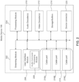
- each video decoder 212 may be configured to decode video of one or more video formats, such as but not limited to MP4 (mp4, m4a, m4v, f4v, f4a, m4b, m4r, f4b, mov), 3GP (3gp, 3gp2, 3g2, 3gpp, 3gpp2), OGG (ogg, oga, ogv, ogx), WMV (wmv, wma, asf), WEBM, FLV, AVI, QuickTime, HDV, MXF (OP1a, OP-Atom), MPEG-TS, MPEG-2 PS, MPEG-2 TS, WAV, Broadcast WAV, LXF, GXF, and/or VOB, to name just some examples.
- MP4 mp4, m4a, m4v, f4v, f4a, m4b, m4r, f4b, mov
- 3GP 3gp, 3g
- Each video decoder 214 may include one or more video codecs, such as but not limited to H.263, H.264, H.265, AVI, HEV, MPEG1, MPEG2, MPEG-TS, MPEG-4, Theora, 3GP, DV, DVCPRO, DVCPRO, DVCProHD, IMX, XDCAM HD, XDCAM HD422, and/or XDCAM EX, to name just some examples.
- video codecs such as but not limited to H.263, H.264, H.265, AVI, HEV, MPEG1, MPEG2, MPEG-TS, MPEG-4, Theora, 3GP, DV, DVCPRO, DVCPRO, DVCProHD, IMX, XDCAM HD, XDCAM HD422, and/or XDCAM EX, to name just some examples.
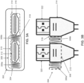
- Both port 312 and port 316 are oriented and positioned horizontally.
- Connector 320 may be inserted into port 312 and connector 322 may be inserted into port 316 (or vice versa).
- Connector 320 includes a rubber cover 310 to provide a grip and protect the connector 320.
- Expandable overmold 304 may be positioned over at least a portion of the rubber cover 310 and is in contact with an outer surface of the rubber cover 310.
- Expandable connector body 308 may comprise an inner portion that is in contact with the outer surface of rubber cover 310 and an outer portion that may comprise an outer surface.
- the inner portion of expandable connector body 308 may be constructed from a flexible material that can be placed around rubber covers of different sizes. For example, the rubber cover of an HDMI connector is typically larger than the rubber cover of a USB-C connector. The inner portion of expandable connector body 308 may be stretched to fit these different sized connectors.
- Expansion mechanism 306a and 306b are configured to expand and contract the expandable connector body.
- the expansion mechanism 306a and 306b may further include a first portion and a second portion.
- the first portion of expansion mechanism 306a and 306b may be connected to or in contact with the inner portion of the expandable connector body 308.
- expansion mechanism 306a and 306b may be configured as a part of expandable connector body 308.
- expansion mechanism 306a and 306b may be configured with an accordion-shape to allow for the expansion and contraction functions.
- portion 318 of the outer surface of expandable connector body 308 is located on right-side portion of expandable connector body 308 (when connector 320 is inserted into port 312) or the left-side portion of expandable connector body 308 (when connector 320 is inserted into port 316).
- the expansion mechanism 306a and 306b may be configured to be activated by a pulling motion on the expansion mechanism 306a and 306b. For example, a user may place his fingers around an outer surface of expandable overmold 304 and cause the expansion mechanism 306a and 306b to expand by a pulling force on one or both sides of the expandable overmold 304.
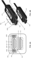
- portion 418 of the outer surface of expandable connector body 408 is located on the lower portion of expandable connector body 408 (when connector 420 is inserted into port 412) or the upper portion of expandable connector body 408 (when connector 420 is inserted into port 416).
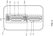
- FIG. 5 illustrates an exemplary port panel 502 with a connector connected to port 512 and a connector connected to port 516, according to some embodiments.
- Port panel 502 is similar to port panel 402 with port 512 and port 516 positioned vertically in relation to each other. However, port 512 and port 516 are oriented vertically in relation to each other.
- Other elements of port panel 502 and expandable overmold 504 function similar to port panel 302 and expandable overmold 304, as described above.
- expandable overmold 504 includes expansion mechanism 506a and 506b and expandable connector body 508 that is configured to be in contact with overmold 514 of a connector that is inserted into port 516. When expanded, a portion 518 of an outer surface of expandable connector body 508 is in contact with and applies a force to the overmold 514 of connector in port 516.
- portion 518 of the outer surface of expandable connector body 408 is located on a right side portion of expandable connector body 508 (when a connector is inserted into port 512) or the left side portion of expandable connector body 508 (when a connector is inserted into port 516).
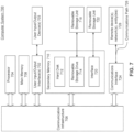
- Computer system 700 may include one or more processors (also called central processing units, or CPUs), such as a processor 704.
- processors also called central processing units, or CPUs
- Processor 704 may be connected to a communication infrastructure or bus 706.
- Computer system 700 may also include user input/output device(s) 703, such as monitors, keyboards, pointing devices, etc., which may communicate with communication infrastructure 706 through user input/output interface(s) 702.
- Computer system 700 may comprise one or more device ports to receive one or more device connectors of user input/output device(s) 703.
- processors 704 may be a graphics processing unit (GPU).
- a GPU may be a processor that is a specialized electronic circuit designed to process mathematically intensive applications.
- the GPU may have a parallel structure that is efficient for parallel processing of large blocks of data, such as mathematically intensive data common to computer graphics applications, images, videos, etc.
- Computer system 700 may also include one or more secondary storage devices or memory 710.
- Secondary memory 710 may include, for example, a hard disk drive 712 and/or a removable storage device or drive 714.
- Removable storage drive 714 may be a floppy disk drive, a magnetic tape drive, a compact disk drive, an optical storage device, tape backup device, and/or any other storage device/drive.
- Computer system 700 may further include a communication or network interface 724.
- Communication interface 724 may enable computer system 700 to communicate and interact with any combination of external devices, external networks, external entities, etc. (individually and collectively referenced by reference number 728).
- communication interface 724 may allow computer system 700 to communicate with external or remote devices 728 over communications path 726, which may be wired and/or wireless (or a combination thereof), and which may include any combination of LANs, WANs, the Internet, etc.
- Control logic and/or data may be transmitted to and from computer system 700 via communication path 726.
- Computer system 700 may also be any of a personal digital assistant (PDA), desktop workstation, laptop or notebook computer, netbook, tablet, smart phone, smart watch or other wearable, appliance, part of the Internet-of Things, and/or embedded system, to name a few non-limiting examples, or any combination thereof.
- PDA personal digital assistant
Landscapes
- Two-Way Televisions, Distribution Of Moving Picture Or The Like (AREA)
- Details Of Connecting Devices For Male And Female Coupling (AREA)
Applications Claiming Priority (1)
| Application Number | Priority Date | Filing Date | Title |
|---|---|---|---|
| US18/148,667 US12431666B2 (en) | 2022-12-30 | 2022-12-30 | Expandable accordion-style cable overmold for secure connection |
Publications (1)
| Publication Number | Publication Date |
|---|---|
| EP4395083A1 true EP4395083A1 (de) | 2024-07-03 |
Family
ID=89474547
Family Applications (1)
| Application Number | Title | Priority Date | Filing Date |
|---|---|---|---|
| EP23220491.7A Pending EP4395083A1 (de) | 2022-12-30 | 2023-12-28 | Ausdehnbare akkordeonartige kabelüberformung für sichere verbindung |
Country Status (4)
| Country | Link |
|---|---|
| US (2) | US12431666B2 (de) |
| EP (1) | EP4395083A1 (de) |
| CN (1) | CN118281634A (de) |
| CA (1) | CA3225328A1 (de) |
Families Citing this family (1)
| Publication number | Priority date | Publication date | Assignee | Title |
|---|---|---|---|---|
| JP7509104B2 (ja) * | 2021-09-17 | 2024-07-02 | 住友電装株式会社 | カバー付きコネクタ、電子ユニット、およびコネクタユニット |
Citations (7)
| Publication number | Priority date | Publication date | Assignee | Title |
|---|---|---|---|---|
| US7390201B1 (en) * | 2005-05-19 | 2008-06-24 | Sandia Corporation | Data port security lock |
| US20090081899A1 (en) * | 2007-09-24 | 2009-03-26 | John Mezzalingua Associates, Inc. | Self-retaining audio/video high definition multi-contact connector and connection method |
| US20100311283A1 (en) * | 2009-06-08 | 2010-12-09 | International Business Machines Corporation | Locking connector for engaging a usb receptacle |
| CN205303835U (zh) * | 2015-10-20 | 2016-06-08 | 贾家新 | 一种计算机防松动usb接口 |
| CN207116811U (zh) * | 2017-08-24 | 2018-03-16 | 东莞市南谷第电子有限公司 | 一种防水对插线 |
| CN208768057U (zh) * | 2018-11-01 | 2019-04-19 | 合肥联睿微电子科技有限公司 | 应用于车载的高稳定性usb蓝牙接收器 |
| CN209626610U (zh) * | 2019-06-06 | 2019-11-12 | 深圳市奥利弗科技有限公司 | 一种接口紧固的hdmi数据线 |
Family Cites Families (11)
| Publication number | Priority date | Publication date | Assignee | Title |
|---|---|---|---|---|
| FR2695260B1 (fr) * | 1992-09-01 | 1994-11-18 | Lectra Systemes Sa | Dispositif de connexion électrique à positionnement automatique. |
| FR2716299B1 (fr) * | 1994-02-16 | 1996-04-19 | Framatome Connectors France | Connecteur flottant à verrouillage temporaire et son application au domaine spatial. |
| US5486117A (en) * | 1994-08-09 | 1996-01-23 | Molex Incorporated | Locking system for an electrical connector assembly |
| JP3488700B2 (ja) * | 2001-05-23 | 2004-01-19 | 山一電機株式会社 | コンタクト端子の駆動方法、および、それが用いられる半導体装置用ソケット |
| JP2003017206A (ja) * | 2001-06-27 | 2003-01-17 | Yamaichi Electronics Co Ltd | 半導体装置用ソケット |
| US6945666B2 (en) * | 2003-06-30 | 2005-09-20 | Monarch Instrument | Illumination device with removable power pack |
| TWM264575U (en) * | 2004-08-19 | 2005-05-11 | Darfon Electronics Corp | Input module and apparatus using the same |
| EP1710869B1 (de) * | 2005-04-05 | 2008-04-30 | Sumitomo Wiring Systems, Ltd. | Verbinderanordnung |
| US7458837B2 (en) * | 2006-01-13 | 2008-12-02 | Advantest Corporation | Connector housing block, interface member and electronic device testing apparatus |
| DE102008006433B4 (de) * | 2008-01-28 | 2011-07-28 | Airbus Operations GmbH, 21129 | Vorrichtung zur Befestigung eines Flugzeugkabinenmoduls |
| US9312625B2 (en) * | 2014-08-06 | 2016-04-12 | Yang Ji Co., Ltd. | Shielding structure of safety socket |
-
2022
- 2022-12-30 US US18/148,667 patent/US12431666B2/en active Active
-
2023
- 2023-12-28 EP EP23220491.7A patent/EP4395083A1/de active Pending
- 2023-12-29 CA CA3225328A patent/CA3225328A1/en active Pending
-
2024
- 2024-01-02 CN CN202410003287.7A patent/CN118281634A/zh active Pending
-
2025
- 2025-09-11 US US19/326,107 patent/US20260011955A1/en active Pending
Patent Citations (7)
| Publication number | Priority date | Publication date | Assignee | Title |
|---|---|---|---|---|
| US7390201B1 (en) * | 2005-05-19 | 2008-06-24 | Sandia Corporation | Data port security lock |
| US20090081899A1 (en) * | 2007-09-24 | 2009-03-26 | John Mezzalingua Associates, Inc. | Self-retaining audio/video high definition multi-contact connector and connection method |
| US20100311283A1 (en) * | 2009-06-08 | 2010-12-09 | International Business Machines Corporation | Locking connector for engaging a usb receptacle |
| CN205303835U (zh) * | 2015-10-20 | 2016-06-08 | 贾家新 | 一种计算机防松动usb接口 |
| CN207116811U (zh) * | 2017-08-24 | 2018-03-16 | 东莞市南谷第电子有限公司 | 一种防水对插线 |
| CN208768057U (zh) * | 2018-11-01 | 2019-04-19 | 合肥联睿微电子科技有限公司 | 应用于车载的高稳定性usb蓝牙接收器 |
| CN209626610U (zh) * | 2019-06-06 | 2019-11-12 | 深圳市奥利弗科技有限公司 | 一种接口紧固的hdmi数据线 |
Also Published As
| Publication number | Publication date |
|---|---|
| US20240222909A1 (en) | 2024-07-04 |
| CA3225328A1 (en) | 2024-06-30 |
| US12431666B2 (en) | 2025-09-30 |
| US20260011955A1 (en) | 2026-01-08 |
| CN118281634A (zh) | 2024-07-02 |
Similar Documents
| Publication | Publication Date | Title |
|---|---|---|
| US20200084342A1 (en) | Dynamically adjusting video to improve synchronization with audio | |
| US20260011955A1 (en) | Expandable accordion-style cable overmold for secure connection | |
| US20260046475A1 (en) | Combined media capability for multiple media devices | |
| US11627368B1 (en) | Automatic offering and switching to a higher quality media stream | |
| US20250358471A1 (en) | Television upgrade | |
| US12034618B2 (en) | IPV6 connectivity test and DNS improvements | |
| US20240015354A1 (en) | Automatic parental control using a remote control or mobile app | |
| US12596411B2 (en) | Cooling subsystems for peripheral devices | |
| EP4250748A1 (de) | Erhaltung der kanalsperre und durchführung dynamischer werbungseinfügung (dai) in einer einrichtung mit mehreren vorrichtungen | |
| US20240080617A1 (en) | Power control for speaker devices in a wireless media system | |
| US12335683B2 (en) | Compression loaded slit shaped waveguide | |
| US12541977B2 (en) | Unsupervised cue point discovery for episodic content | |
| US12579950B2 (en) | LED driver IC for scanning backlight control | |
| US12452479B2 (en) | Displaying multimedia segments in a display device | |
| US20260095621A1 (en) | Artificial intelligence (ai) audio enhancement |
Legal Events
| Date | Code | Title | Description |
|---|---|---|---|
| PUAI | Public reference made under article 153(3) epc to a published international application that has entered the european phase |
Free format text: ORIGINAL CODE: 0009012 |
|
| STAA | Information on the status of an ep patent application or granted ep patent |
Free format text: STATUS: THE APPLICATION HAS BEEN PUBLISHED |
|
| AK | Designated contracting states |
Kind code of ref document: A1 Designated state(s): AL AT BE BG CH CY CZ DE DK EE ES FI FR GB GR HR HU IE IS IT LI LT LU LV MC ME MK MT NL NO PL PT RO RS SE SI SK SM TR |
|
| STAA | Information on the status of an ep patent application or granted ep patent |
Free format text: STATUS: REQUEST FOR EXAMINATION WAS MADE |
|
| 17P | Request for examination filed |
Effective date: 20250103 |