EP4395031A1 - Replaceable battery module - Google Patents
Replaceable battery module Download PDFInfo
- Publication number
- EP4395031A1 EP4395031A1 EP23796705.4A EP23796705A EP4395031A1 EP 4395031 A1 EP4395031 A1 EP 4395031A1 EP 23796705 A EP23796705 A EP 23796705A EP 4395031 A1 EP4395031 A1 EP 4395031A1
- Authority
- EP
- European Patent Office
- Prior art keywords
- battery pack
- inclined protrusion
- battery module
- locking member
- module according
- Prior art date
- Legal status (The legal status is an assumption and is not a legal conclusion. Google has not performed a legal analysis and makes no representation as to the accuracy of the status listed.)
- Granted
Links
Images

Classifications
-
- H—ELECTRICITY
- H01—ELECTRIC ELEMENTS
- H01M—PROCESSES OR MEANS, e.g. BATTERIES, FOR THE DIRECT CONVERSION OF CHEMICAL ENERGY INTO ELECTRICAL ENERGY
- H01M50/00—Constructional details or processes of manufacture of the non-active parts of electrochemical cells other than fuel cells, e.g. hybrid cells
- H01M50/20—Mountings; Secondary casings or frames; Racks, modules or packs; Suspension devices; Shock absorbers; Transport or carrying devices; Holders
- H01M50/244—Secondary casings; Racks; Suspension devices; Carrying devices; Holders characterised by their mounting method
-
- B—PERFORMING OPERATIONS; TRANSPORTING
- B60—VEHICLES IN GENERAL
- B60K—ARRANGEMENT OR MOUNTING OF PROPULSION UNITS OR OF TRANSMISSIONS IN VEHICLES; ARRANGEMENT OR MOUNTING OF PLURAL DIVERSE PRIME-MOVERS IN VEHICLES; AUXILIARY DRIVES FOR VEHICLES; INSTRUMENTATION OR DASHBOARDS FOR VEHICLES; ARRANGEMENTS IN CONNECTION WITH COOLING, AIR INTAKE, GAS EXHAUST OR FUEL SUPPLY OF PROPULSION UNITS IN VEHICLES
- B60K1/00—Arrangement or mounting of electrical propulsion units
- B60K1/04—Arrangement or mounting of electrical propulsion units of the electric storage means for propulsion
-
- B—PERFORMING OPERATIONS; TRANSPORTING
- B60—VEHICLES IN GENERAL
- B60L—PROPULSION OF ELECTRICALLY-PROPELLED VEHICLES; SUPPLYING ELECTRIC POWER FOR AUXILIARY EQUIPMENT OF ELECTRICALLY-PROPELLED VEHICLES; ELECTRODYNAMIC BRAKE SYSTEMS FOR VEHICLES IN GENERAL; MAGNETIC SUSPENSION OR LEVITATION FOR VEHICLES; MONITORING OPERATING VARIABLES OF ELECTRICALLY-PROPELLED VEHICLES; ELECTRIC SAFETY DEVICES FOR ELECTRICALLY-PROPELLED VEHICLES
- B60L50/00—Electric propulsion with power supplied within the vehicle
- B60L50/50—Electric propulsion with power supplied within the vehicle using propulsion power supplied by batteries or fuel cells
- B60L50/60—Electric propulsion with power supplied within the vehicle using propulsion power supplied by batteries or fuel cells using power supplied by batteries
- B60L50/64—Constructional details of batteries specially adapted for electric vehicles
-
- B—PERFORMING OPERATIONS; TRANSPORTING
- B60—VEHICLES IN GENERAL
- B60L—PROPULSION OF ELECTRICALLY-PROPELLED VEHICLES; SUPPLYING ELECTRIC POWER FOR AUXILIARY EQUIPMENT OF ELECTRICALLY-PROPELLED VEHICLES; ELECTRODYNAMIC BRAKE SYSTEMS FOR VEHICLES IN GENERAL; MAGNETIC SUSPENSION OR LEVITATION FOR VEHICLES; MONITORING OPERATING VARIABLES OF ELECTRICALLY-PROPELLED VEHICLES; ELECTRIC SAFETY DEVICES FOR ELECTRICALLY-PROPELLED VEHICLES
- B60L50/00—Electric propulsion with power supplied within the vehicle
- B60L50/50—Electric propulsion with power supplied within the vehicle using propulsion power supplied by batteries or fuel cells
- B60L50/60—Electric propulsion with power supplied within the vehicle using propulsion power supplied by batteries or fuel cells using power supplied by batteries
- B60L50/66—Arrangements of batteries
-
- B—PERFORMING OPERATIONS; TRANSPORTING
- B60—VEHICLES IN GENERAL
- B60L—PROPULSION OF ELECTRICALLY-PROPELLED VEHICLES; SUPPLYING ELECTRIC POWER FOR AUXILIARY EQUIPMENT OF ELECTRICALLY-PROPELLED VEHICLES; ELECTRODYNAMIC BRAKE SYSTEMS FOR VEHICLES IN GENERAL; MAGNETIC SUSPENSION OR LEVITATION FOR VEHICLES; MONITORING OPERATING VARIABLES OF ELECTRICALLY-PROPELLED VEHICLES; ELECTRIC SAFETY DEVICES FOR ELECTRICALLY-PROPELLED VEHICLES
- B60L53/00—Methods of charging batteries, specially adapted for electric vehicles; Charging stations or on-board charging equipment therefor; Exchange of energy storage elements in electric vehicles
- B60L53/80—Exchanging energy storage elements, e.g. removable batteries
-
- H—ELECTRICITY
- H01—ELECTRIC ELEMENTS
- H01M—PROCESSES OR MEANS, e.g. BATTERIES, FOR THE DIRECT CONVERSION OF CHEMICAL ENERGY INTO ELECTRICAL ENERGY
- H01M50/00—Constructional details or processes of manufacture of the non-active parts of electrochemical cells other than fuel cells, e.g. hybrid cells
- H01M50/20—Mountings; Secondary casings or frames; Racks, modules or packs; Suspension devices; Shock absorbers; Transport or carrying devices; Holders
- H01M50/204—Racks, modules or packs for multiple batteries or multiple cells
-
- H—ELECTRICITY
- H01—ELECTRIC ELEMENTS
- H01M—PROCESSES OR MEANS, e.g. BATTERIES, FOR THE DIRECT CONVERSION OF CHEMICAL ENERGY INTO ELECTRICAL ENERGY
- H01M50/00—Constructional details or processes of manufacture of the non-active parts of electrochemical cells other than fuel cells, e.g. hybrid cells
- H01M50/20—Mountings; Secondary casings or frames; Racks, modules or packs; Suspension devices; Shock absorbers; Transport or carrying devices; Holders
- H01M50/249—Mountings; Secondary casings or frames; Racks, modules or packs; Suspension devices; Shock absorbers; Transport or carrying devices; Holders specially adapted for aircraft or vehicles, e.g. cars or trains
-
- H—ELECTRICITY
- H01—ELECTRIC ELEMENTS
- H01M—PROCESSES OR MEANS, e.g. BATTERIES, FOR THE DIRECT CONVERSION OF CHEMICAL ENERGY INTO ELECTRICAL ENERGY
- H01M50/00—Constructional details or processes of manufacture of the non-active parts of electrochemical cells other than fuel cells, e.g. hybrid cells
- H01M50/20—Mountings; Secondary casings or frames; Racks, modules or packs; Suspension devices; Shock absorbers; Transport or carrying devices; Holders
- H01M50/262—Mountings; Secondary casings or frames; Racks, modules or packs; Suspension devices; Shock absorbers; Transport or carrying devices; Holders with fastening means, e.g. locks
-
- H—ELECTRICITY
- H01—ELECTRIC ELEMENTS
- H01M—PROCESSES OR MEANS, e.g. BATTERIES, FOR THE DIRECT CONVERSION OF CHEMICAL ENERGY INTO ELECTRICAL ENERGY
- H01M50/00—Constructional details or processes of manufacture of the non-active parts of electrochemical cells other than fuel cells, e.g. hybrid cells
- H01M50/20—Mountings; Secondary casings or frames; Racks, modules or packs; Suspension devices; Shock absorbers; Transport or carrying devices; Holders
- H01M50/262—Mountings; Secondary casings or frames; Racks, modules or packs; Suspension devices; Shock absorbers; Transport or carrying devices; Holders with fastening means, e.g. locks
- H01M50/264—Mountings; Secondary casings or frames; Racks, modules or packs; Suspension devices; Shock absorbers; Transport or carrying devices; Holders with fastening means, e.g. locks for cells or batteries, e.g. straps, tie rods or peripheral frames
-
- B—PERFORMING OPERATIONS; TRANSPORTING
- B60—VEHICLES IN GENERAL
- B60K—ARRANGEMENT OR MOUNTING OF PROPULSION UNITS OR OF TRANSMISSIONS IN VEHICLES; ARRANGEMENT OR MOUNTING OF PLURAL DIVERSE PRIME-MOVERS IN VEHICLES; AUXILIARY DRIVES FOR VEHICLES; INSTRUMENTATION OR DASHBOARDS FOR VEHICLES; ARRANGEMENTS IN CONNECTION WITH COOLING, AIR INTAKE, GAS EXHAUST OR FUEL SUPPLY OF PROPULSION UNITS IN VEHICLES
- B60K1/00—Arrangement or mounting of electrical propulsion units
- B60K1/04—Arrangement or mounting of electrical propulsion units of the electric storage means for propulsion
- B60K2001/0455—Removal or replacement of the energy storages
-
- B—PERFORMING OPERATIONS; TRANSPORTING
- B60—VEHICLES IN GENERAL
- B60K—ARRANGEMENT OR MOUNTING OF PROPULSION UNITS OR OF TRANSMISSIONS IN VEHICLES; ARRANGEMENT OR MOUNTING OF PLURAL DIVERSE PRIME-MOVERS IN VEHICLES; AUXILIARY DRIVES FOR VEHICLES; INSTRUMENTATION OR DASHBOARDS FOR VEHICLES; ARRANGEMENTS IN CONNECTION WITH COOLING, AIR INTAKE, GAS EXHAUST OR FUEL SUPPLY OF PROPULSION UNITS IN VEHICLES
- B60K1/00—Arrangement or mounting of electrical propulsion units
- B60K1/04—Arrangement or mounting of electrical propulsion units of the electric storage means for propulsion
- B60K2001/0455—Removal or replacement of the energy storages
- B60K2001/0472—Removal or replacement of the energy storages from below
-
- B—PERFORMING OPERATIONS; TRANSPORTING
- B60—VEHICLES IN GENERAL
- B60Y—INDEXING SCHEME RELATING TO ASPECTS CROSS-CUTTING VEHICLE TECHNOLOGY
- B60Y2200/00—Type of vehicle
- B60Y2200/10—Road Vehicles
- B60Y2200/12—Motorcycles, Trikes; Quads; Scooters
- B60Y2200/126—Scooters
-
- B—PERFORMING OPERATIONS; TRANSPORTING
- B60—VEHICLES IN GENERAL
- B60Y—INDEXING SCHEME RELATING TO ASPECTS CROSS-CUTTING VEHICLE TECHNOLOGY
- B60Y2200/00—Type of vehicle
- B60Y2200/80—Other vehicles not covered by groups B60Y2200/10 - B60Y2200/60
- B60Y2200/86—Carts; Golf carts
-
- B—PERFORMING OPERATIONS; TRANSPORTING
- B60—VEHICLES IN GENERAL
- B60Y—INDEXING SCHEME RELATING TO ASPECTS CROSS-CUTTING VEHICLE TECHNOLOGY
- B60Y2200/00—Type of vehicle
- B60Y2200/90—Vehicles comprising electric prime movers
- B60Y2200/91—Electric vehicles
-
- H—ELECTRICITY
- H01—ELECTRIC ELEMENTS
- H01M—PROCESSES OR MEANS, e.g. BATTERIES, FOR THE DIRECT CONVERSION OF CHEMICAL ENERGY INTO ELECTRICAL ENERGY
- H01M2220/00—Batteries for particular applications
- H01M2220/20—Batteries in motive systems, e.g. vehicle, ship, plane
-
- Y—GENERAL TAGGING OF NEW TECHNOLOGICAL DEVELOPMENTS; GENERAL TAGGING OF CROSS-SECTIONAL TECHNOLOGIES SPANNING OVER SEVERAL SECTIONS OF THE IPC; TECHNICAL SUBJECTS COVERED BY FORMER USPC CROSS-REFERENCE ART COLLECTIONS [XRACs] AND DIGESTS
- Y02—TECHNOLOGIES OR APPLICATIONS FOR MITIGATION OR ADAPTATION AGAINST CLIMATE CHANGE
- Y02E—REDUCTION OF GREENHOUSE GAS [GHG] EMISSIONS, RELATED TO ENERGY GENERATION, TRANSMISSION OR DISTRIBUTION
- Y02E60/00—Enabling technologies; Technologies with a potential or indirect contribution to GHG emissions mitigation
- Y02E60/10—Energy storage using batteries
-
- Y—GENERAL TAGGING OF NEW TECHNOLOGICAL DEVELOPMENTS; GENERAL TAGGING OF CROSS-SECTIONAL TECHNOLOGIES SPANNING OVER SEVERAL SECTIONS OF THE IPC; TECHNICAL SUBJECTS COVERED BY FORMER USPC CROSS-REFERENCE ART COLLECTIONS [XRACs] AND DIGESTS
- Y02—TECHNOLOGIES OR APPLICATIONS FOR MITIGATION OR ADAPTATION AGAINST CLIMATE CHANGE
- Y02T—CLIMATE CHANGE MITIGATION TECHNOLOGIES RELATED TO TRANSPORTATION
- Y02T10/00—Road transport of goods or passengers
- Y02T10/60—Other road transportation technologies with climate change mitigation effect
- Y02T10/70—Energy storage systems for electromobility, e.g. batteries
-
- Y—GENERAL TAGGING OF NEW TECHNOLOGICAL DEVELOPMENTS; GENERAL TAGGING OF CROSS-SECTIONAL TECHNOLOGIES SPANNING OVER SEVERAL SECTIONS OF THE IPC; TECHNICAL SUBJECTS COVERED BY FORMER USPC CROSS-REFERENCE ART COLLECTIONS [XRACs] AND DIGESTS
- Y02—TECHNOLOGIES OR APPLICATIONS FOR MITIGATION OR ADAPTATION AGAINST CLIMATE CHANGE
- Y02T—CLIMATE CHANGE MITIGATION TECHNOLOGIES RELATED TO TRANSPORTATION
- Y02T10/00—Road transport of goods or passengers
- Y02T10/60—Other road transportation technologies with climate change mitigation effect
- Y02T10/7072—Electromobility specific charging systems or methods for batteries, ultracapacitors, supercapacitors or double-layer capacitors
Definitions
- the present invention relates to a replaceable battery module, and an electric vehicle and a battery swap station comprising the same.
- LEV Light electric vehicle
- the battery swap method means a method of replacing a used battery with a fully charged battery, and the battery swap method can provide convenience to an electric vehicle driver because the battery can be replaced within a short time.
- a replaceable battery module which comprises a battery pack including a groove formed on an outer circumferential surface and a locking member movably provided in the groove, and a battery pack mounting part having a mounting space, in which the battery pack is accommodated, and an inclined protrusion detachably locked and fixed to the locking member so that a position of the battery pack disposed in the mounting space is fixed.
- the locking member may pass through the inclined protrusion after contacting the inclined protrusion, and be locked and foxed to the inclined protrusion after passing through the inclined protrusion.
- the wing part may be spaced apart from the bottom surface of the groove and may extend from one sidewall of the groove.
- the locking member may comprise one end connected to the wing part to fix the position and the other end having a hook-type head part and movably provided in a first direction closer to the bottom surface of the groove or a second direction farther from the bottom surface of the groove.
- the hook-type head part may comprise an interference-fitting part provided so that the thickness is reduced along the mounting direction of the battery pack so as to pass through the inclined protrusion with interference-fitting, and a locking fixing part provided so that the thickness is increased along the mounting direction of the battery pack so as to be locked and fixed with the inclined protrusion when the passage is completed.
- the inclined protrusion may have an outside inclined part contacting the interference-fitting part when the battery pack is mounted and provided so that the thickness increases along the mounting direction of the battery pack, and an inside inclined part contacting the locking fixing part after the hook-type head part passes through the outside inclined part and provided so that the thickness decreases along the mounting direction of the battery pack.
- the locking member when an external force is applied to the battery pack along the mounting direction of the battery pack, the locking member may pass through the inclined protrusion and be mounted within the mounting space.
- the interference-fitting part when the battery pack is mounted in the mounting space, the interference-fitting part may pass through the inclined protrusion while sliding along the outside inclined part of the inclined protrusion.
- the locking member may be formed of an elastic material, and the locking member may be provided so that a partial region is bent when an external force is applied thereto.
- an electric vehicle comprising the replaceable battery module is provided.
- the electric vehicle (300) according to one example of the present invention comprises the replaceable battery module.
- the battery swap station (400) according to one example of the present invention comprises the replaceable battery module.
- the replaceable battery module may be applied to a light electronic vehicle (LEV) or a battery swap station (also referred to as a 'battery charging station').
- the battery pack (100) comprises a groove (110) formed on an outer circumferential surface and a hook-type locking member (120) connected to the sidewall (113) of the groove (110).
- the battery pack (200) may be provided with the grooves (110) and locking members (120) by one set on both sides in the mounting direction (M). That is, the battery pack (100) may comprise two sets of grooves (110) and hook-type locking members (120).
- the hook-type locking member (120) is in a hook type, which is a hook-shaped locking member that is locked and fixed to the inclined protrusion (220), where the hook-type locking member (120) may be disposed so that the hook portion faces the outside of the battery pack (100).
- the hook portion may be disposed to face the inner surface of the battery pack mounting part (200).
- the battery pack (100) may have a width (W1) of the front end (100a) and a width (W2) of the rear end (100b) that are different from each other.
- the front end (100a) of the battery pack (100) is the part that first enters the mounting space (210) when sliding along the mounting direction (M), and the region located in the opposite direction to the front end (100a) is referred to as the rear end (100b).
- the width of the front end (100a) may be formed to be relatively narrower than the width of the rear end (100b) so that the battery pack (100) is easy to enter into the mounting space (210).
- a wing part (112) extending along the mounting direction (M) of the battery pack (100) may be provided in the groove (110), and the locking member (120) may be connected to the wing part (112). At this time, the wing part (112) may be spaced apart from the bottom surface (111) of the groove (110), and extend from one sidewall (113) of the groove (110).
- the locking member (120) may comprise one end (121) connected to the wing part (112) to fix the position, and the other end (122) movably provided in a first direction (h1) closer to the bottom surface (111) of the groove (110) or a second direction (h2) farther from the bottom surface (111) of the groove (110).
- the other end (122) may have a hook-type head part.
- the external force may be, for example, a force pressed from the inclined protrusion (120) when passing through the inclined protrusion (220).
- the hook-type head part (122) may be pressed from the inclined protrusion (220) to move in the first direction (h1), and referring to Figure 3 , when the passage of the hook-type head part (122) through the inclined protrusion (220) is completed, the hook-type head part (122) may move in the second direction (h2) as the force pressed from the inclined protrusion (220) is released.
- the locking fixing part (122b) may be positioned closer to one end (121) side than the interference-fitting part (122a).
- the inclination angle of the first inclined surface in the interference-fitting part (122) may be gentler than the inclination angle of the second inclined surface in the locking fixing part (122b).
- the hook-type locking member (120) may be formed of an elastic material.
- the hook-type locking member (120) may be formed of a POM material. As the hook-type locking member (120) is formed of an elastic material, it may be pressed from the inclined protrusion (220) to move in the first direction (h1), and then when the pressed force is released, it may return to the original position while moving in the second direction (h2).
- the replaceable battery module according to the present invention may further comprise a cover (not shown) coupled to the battery pack mounting part (200).
- the present invention may be an electric vehicle (300) comprising the above-described replaceable battery module.
- the electric vehicle (300) comprises a battery pack mounting part (200), where a battery pack may be detachably mounted on the battery pack mounting part (200).
- the type of the electric vehicle (300) is not particularly limited if the replaceable battery pack may be mounted, which may be a small, medium, or large electric vehicle, and preferably may be a small electric vehicle.
- the small electric vehicle may be exemplified by, for example, an electric scooter, an electric bicycle, or a quick board, and the like.
- the electric vehicle comprising the above-described replaceable battery pack has an advantage of shortening a replacement time when replacing an old battery pack with a new battery pack.
- the present invention relates to a battery swap station (400) comprising the above-described replaceable battery module.
- the battery swap station (400) may supply power to the battery pack through the battery pack mounting part (200) to charge the battery pack.
- the battery swap station comprising the above-described replaceable battery pack has an advantage that the replacement time consumed when mounting an old battery pack or separating a fully charged battery pack is reduced.
Landscapes
- Engineering & Computer Science (AREA)
- Chemical & Material Sciences (AREA)
- Chemical Kinetics & Catalysis (AREA)
- Electrochemistry (AREA)
- General Chemical & Material Sciences (AREA)
- Transportation (AREA)
- Mechanical Engineering (AREA)
- Power Engineering (AREA)
- Aviation & Aerospace Engineering (AREA)
- Life Sciences & Earth Sciences (AREA)
- Sustainable Development (AREA)
- Sustainable Energy (AREA)
- Combustion & Propulsion (AREA)
- Battery Mounting, Suspending (AREA)
- Arrangement Or Mounting Of Propulsion Units For Vehicles (AREA)
Abstract
Description
- The present invention relates to a replaceable battery module, and an electric vehicle and a battery swap station comprising the same.
- The present application claims the benefit of priority based on
Korean Patent Application No. 10-2022-0050511 dated April 25, 2022 - Light electric vehicle (LEV) markets are proposed as a solution to the problem of traffic congestion and parking shortage in large cities, and their use expands to various fields such as tourist destinations, golf carts, and distribution warehouses.
- A small electric vehicle equipped with a battery pack requires battery charging for driving, but has a disadvantage that it takes a long time to charge the battery.
- Recently, in order to shorten the battery charging time, a battery swap method has been considered. The battery swap method means a method of replacing a used battery with a fully charged battery, and the battery swap method can provide convenience to an electric vehicle driver because the battery can be replaced within a short time.
- It is a problem to be solved by the present invention to provide a replaceable battery module capable of quickly replacing a battery pack through a simple coupling structure, and an electric vehicle and a battery swap station comprising the same.
- In order to solve the above problem, according to one aspect of the present invention, a replaceable battery module is provided, which comprises a battery pack including a groove formed on an outer circumferential surface and a locking member movably provided in the groove, and a battery pack mounting part having a mounting space, in which the battery pack is accommodated, and an inclined protrusion detachably locked and fixed to the locking member so that a position of the battery pack disposed in the mounting space is fixed.
- Also, when a force is applied in the mounting direction to mount the battery pack in the mounting space, the locking member may pass through the inclined protrusion after contacting the inclined protrusion, and be locked and foxed to the inclined protrusion after passing through the inclined protrusion.
- In addition, a wing part extending along the mounting direction of the battery pack may be provided in the groove. Furthermore, the locking member may be connected to the wing part.
- Also, the wing part may be spaced apart from the bottom surface of the groove and may extend from one sidewall of the groove.
- In addition, the locking member may comprise one end connected to the wing part to fix the position and the other end having a hook-type head part and movably provided in a first direction closer to the bottom surface of the groove or a second direction farther from the bottom surface of the groove.
- Also, the other end of the locking member may be provided so that the hook-type head part is pressed by the inclined projection to move in the first direction when passing through the inclined projection in an interference-fitting manner. In addition, the other end of the locking member may be provided so that the hook-type head part is released from the force pressed by the inclined protrusion to move in the second direction when completing the passage of the inclined protrusion.
- Furthermore, the hook-type head part may comprise an interference-fitting part provided so that the thickness is reduced along the mounting direction of the battery pack so as to pass through the inclined protrusion with interference-fitting, and a locking fixing part provided so that the thickness is increased along the mounting direction of the battery pack so as to be locked and fixed with the inclined protrusion when the passage is completed.
- Also, the inclined protrusion may have an outside inclined part contacting the interference-fitting part when the battery pack is mounted and provided so that the thickness increases along the mounting direction of the battery pack, and an inside inclined part contacting the locking fixing part after the hook-type head part passes through the outside inclined part and provided so that the thickness decreases along the mounting direction of the battery pack.
- In addition, when an external force is applied to the battery pack along the mounting direction of the battery pack, the locking member may pass through the inclined protrusion and be mounted within the mounting space. At this instance, when the battery pack is mounted in the mounting space, the interference-fitting part may pass through the inclined protrusion while sliding along the outside inclined part of the inclined protrusion.
- Furthermore, when an external force is applied to the battery pack in a direction opposite to the mounting direction of the battery pack, the locking member may pass through the inclined protrusion, and deviate from the inclined protrusion, and the battery pack may be separated out of the mounting space. At this instance, when the battery pack mounted in the mounting space is separated, the locking fixing part may pass through the inclined protrusion while sliding along the inside inclined part of the inclined protrusion.
- Also, the locking member may be formed of an elastic material, and the locking member may be provided so that a partial region is bent when an external force is applied thereto.
- In addition, according to another aspect of the present invention, an electric vehicle comprising the replaceable battery module is provided.
- Furthermore, according to another aspect of the present invention, a battery swap station comprising the replaceable battery module is provided.
- As described above, the replaceable battery module related to at least one example of the present invention, and the electric vehicle and the battery swap station comprising the same have the following effects.
- The battery pack can be easily attached and detached through the hook structure in which the battery pack is locked and fixed in the battery pack mounting part in an interference-fitting manner, and thus the replacement of the battery pack can be quickly made.
-
-
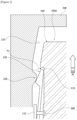
Figure 1 is a cross-sectional diagram of a replaceable battery module according to one example of the present invention. -
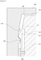
Figures 2 and3 are operating state diagrams for explaining a process of mounting a battery pack in the replaceable battery module shown inFigure 1 . -
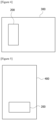
Figure 4 is a configuration diagram schematically showing an electric vehicle related to one example of the present invention. -
Figure 5 is a configuration diagram schematically showing a battery swap station related to one example of the present invention. - Hereinafter, a replaceable battery module according to one example of the present invention, and an electric vehicle and a battery swap station comprising the same will be described in detail with reference to the drawings.
- In addition, regardless of the reference numerals, the same or corresponding components are given by the same or similar reference numerals, duplicate descriptions thereof will be omitted, and for convenience of explanation, the size and shape of each component member as shown can be exaggerated or reduced.
-
Figure 1 is a cross-sectional diagram of a replaceable battery module according to one example of the present invention, andFigures 2 and3 are operating state diagrams for explaining a process of mounting a battery pack (100) in the replaceable battery module shown inFigure 1 . - Specifically,
Figure 2 is a diagram for explaining an interference fit process when a battery pack (100) is mounted, andFigure 3 is a diagram showing a mounting completion state of the battery pack (100). -
Figure 4 is a configuration diagram schematically showing an electric vehicle (300) related to one example of the present invention, andFigure 5 is a configuration diagram schematically showing a battery swap station (400) related to one example of the present invention. - The present invention relates to a replaceable battery module.
- Also, the electric vehicle (300) according to one example of the present invention comprises the replaceable battery module. In addition, the battery swap station (400) according to one example of the present invention comprises the replaceable battery module. In detail, the replaceable battery module may be applied to a light electronic vehicle (LEV) or a battery swap station (also referred to as a 'battery charging station').
- Referring to
Figures 1 to 3 , the replaceable battery module according to one example of the present invention comprises a battery pack (100) and a battery pack mounting part (200). - The battery pack mounting part (200) may be provided in an electric vehicle (300), or may be provided in a battery charging station (400).
- In addition, the battery pack (100) may be electrically connected to the battery pack mounting part (200) in a state of being mounted on the battery pack mounting part (200). As the battery pack (100) and the battery pack mounting part (200) are electrically connected to each other, a power is supplied from the battery charging station (400) to the battery pack (100) so that the battery pack (100) may be charged. In addition, a power may be supplied from the battery pack (100) to a motor that is a driving source of the electric vehicle (300).
- The replaceable battery module comprises a battery pack (100) including a groove (110) formed on an exterior surface and a locking member (120) movably provided in the groove (110). In addition, the replaceable battery module comprises a battery pack mounting part (200) having a mounting space (210), in which the battery pack (100) is accommodated, and an inclined protrusion (220) detachably locked and fixed to the locking member (120) so that a position of the battery pack (100) disposed in the mounting space (210) is fixed. The inclined protrusion (220) is provided to protrude into the mounting space (210).
- The locking member (120) may be referred to as a hook-type locking member.
- Specifically, the battery pack (100) comprises a groove (110) formed on an outer circumferential surface and a hook-type locking member (120) connected to the sidewall (113) of the groove (110).
- In addition, the battery pack (200) may be provided with the grooves (110) and locking members (120) by one set on both sides in the mounting direction (M). That is, the battery pack (100) may comprise two sets of grooves (110) and hook-type locking members (120).
- In the present invention, the hook-type locking member (120) is in a hook type, which is a hook-shaped locking member that is locked and fixed to the inclined protrusion (220), where the hook-type locking member (120) may be disposed so that the hook portion faces the outside of the battery pack (100). For example, in a mounting state of the battery pack (100), the hook portion may be disposed to face the inner surface of the battery pack mounting part (200).
- The battery pack (100) may comprise a plurality of secondary battery cells (E) accommodated therein.
- Also, the battery pack (100) may have a width (W1) of the front end (100a) and a width (W2) of the rear end (100b) that are different from each other.
- The front end (100a) of the battery pack (100) is the part that first enters the mounting space (210) when sliding along the mounting direction (M), and the region located in the opposite direction to the front end (100a) is referred to as the rear end (100b). The width of the front end (100a) may be formed to be relatively narrower than the width of the rear end (100b) so that the battery pack (100) is easy to enter into the mounting space (210).
- In addition, the battery pack (100) may comprise a handle (130) provided on the side of the rear end (100b).
- The battery pack mounting part (200) has a mounting space (210) in which the battery pack (100) is detachably mounted, and an inclined protrusion (220) locked and fixed to the locking member (120) with interference-fitting so that the position of the mounted battery pack (100) is fixed. In order to mount the battery pack (100), a certain amount of force is required in the mounting direction (M).
- For example, when the battery pack (100) is mounted in the mounting space (210), the hook portion of the hook-type locking member (120) comes into contact with the inclined protrusion (220) to prevent movement, where the hook-type engaging member (120) may pass through the inclined protrusion (220), and be locked and fixed to the inclined protrusion (220) in an interference-fitting manner.
- In the replaceable battery module according to one example of the present invention, the battery pack (100) may be locked and fixed to the battery pack mounting part (200) through the hook-type locking member (120) and the inclined protrusion (220) having a relatively simple structure.
- When a force is applied in the mounting direction (M) to mount the battery pack (100) in the mounting space (210), the locking member (120) may pass through the inclined protrusion (220) after contacting the inclined protrusion (220), and may be locked and fixed to the inclined protrusion (220) after passing through the inclined protrusion (220). Specifically, upon mounting the battery pack (100) in the mounting space (210) along the mounting direction (M), the hook-type locking member (120) may pass through the inclined protrusion (220) with interference-fitting when a certain or more force is applied in the mounting direction (M), and may be locked and fixed to the inclined protrusion when the passage is completed.
- Conversely, in order to separate the battery pack (100) mounted in the mounting space (210), when a certain amount of force is applied in the opposite direction to the mounting direction (M), the locked and fixed hook-type locking member (120) passes through the inclined protrusion (220) in the interference-fitting manner, and is separated from the inclined protrusion, whereby the locking and fixing may be released.
- In addition, a wing part (112) extending along the mounting direction (M) of the battery pack (100) may be provided in the groove (110), and the locking member (120) may be connected to the wing part (112). At this time, the wing part (112) may be spaced apart from the bottom surface (111) of the groove (110), and extend from one sidewall (113) of the groove (110).
- As one example, the groove (110) may comprise a wing part (112) formed by extending from one sidewall (113) to the central portion of the groove (110) at a regular interval from the bottom surface (111) of the groove, and the hook-type locking member (120) may be connected to the wing part (112).
- The hook-type locking member (120) may be connected to the inner surface of the wing part (112) facing the bottom surface (111) of the groove (110). The replaceable battery module may comprise a separate connection member (300) connecting the hook-type locking member (120) and the inner surface of the wing part (112), and for example, the connection member (300) may be a screw. However, the connection member (300) is not limited to the screw, and various types of well-known connection parts, or connection methods may be used without limitation.
- The locking member (120) may comprise one end (121) connected to the wing part (112) to fix the position, and the other end (122) movably provided in a first direction (h1) closer to the bottom surface (111) of the groove (110) or a second direction (h2) farther from the bottom surface (111) of the groove (110). The other end (122) may have a hook-type head part.
- The hook-type locking member (120) has a predetermined length. One end (121) of the locking member (120) may be connected to the wing part (112) to fix the position, and the position of the other end (122) may be moved. The other end (122) refers to the end in the opposite direction of one end (121).
- The locking member (120) may be formed of an elastic material, and the locking member (120) may be provided so that a partial region is bent when an external force is applied. At this time, when an external force is applied, the other end (122) may be bent, and the position may be moved in the first direction (h1) or the second direction (h2).
- In addition, the other end (122) may be provided with a hook-shaped hook-type head part. The hook-type head part may be formed by adjusting the thickness of the other end (122). In this document, the other end (122) may be understood to refer to a hook-type head part.
- The hook-type head part (122) may be locked and fixed to the inclined protrusion (220) with the interference-fitting. The hook-type head part (122) of the hook-type locking member (120) may move in the first direction (h1) by an external force, and may return to its original position while moving in the second direction (h2) when the external force is released.
- The external force may be, for example, a force pressed from the inclined protrusion (120) when passing through the inclined protrusion (220).
- Referring to
Figure 2 , when the other end (122) of the locking member (120) passes through the inclined protrusion (220) in the interference-fitting manner, the hook-type head part (122) may be pressed from the inclined protrusion (220) to move in the first direction (h1), and referring toFigure 3 , when the passage of the hook-type head part (122) through the inclined protrusion (220) is completed, the hook-type head part (122) may move in the second direction (h2) as the force pressed from the inclined protrusion (220) is released. - In one example, the hook-type head part (122) may comprise an interference-fitting part (122a) provided so that the thickness is reduced along the mounting direction (M) of the battery pack (100) so as to be capable of passing through the inclined protrusion (220) with interference-fitting, and a locking fixing part (122b) provided so that the thickness is increased along the mounting direction (M) of the battery pack (100) so as to be locked and fixed with the inclined protrusion (220) when the passage through the inclined protrusion (220) is completed.
- That is, by adjusting the thickness of the other end (122) of the locking member (120) along the mounting direction (M) of the battery pack (100), the interference-fitting part (122a) and the locking fixing part (122b) may be formed.
- The interference-fitting part (122a) may have a first inclined surface formed to be inclined to be capable of passing through the inclined protrusion (220) with interference-fitting, and the locking fixing part (122b) may have a second inclined surface formed to be inclined to be locked and fixed to the inclined protrusion (220) when the passage of the hook-type head part (122) is completed. At this time, the first and second inclined surfaces may be inclined in opposite directions to each other.
- The locking fixing part (122b) may be positioned closer to one end (121) side than the interference-fitting part (122a). The inclination angle of the first inclined surface in the interference-fitting part (122) may be gentler than the inclination angle of the second inclined surface in the locking fixing part (122b).
- Also, the force required for interference-fitting may be changed according to the inclination angle of the first inclined surface, and the inclination angle of the second inclined surface in the locking fixing part (122b) may be formed at a predetermined angle or more to prevent separation after locking and fixing to the inclined protrusion (220).
- In addition, the inclined protrusion (220) may have an outside inclined part (221) contacting the interference-fitting part (122a) when the battery pack (100) is mounted and provided so that the thickness increases along the mounting direction (M) of the battery pack (100), and an inside inclined part (222) contacting the locking fixing part (122b) after the hook-type head part (122) passes through the outside inclined part (221) and provided so that the thickness decreases along the mounting direction (M) of the battery pack (100).
- The outside inclined part (221) may be formed to be inclined at an inclination angle corresponding to the first inclined surface of the interference-fitting part (122a), and the inside inclined part (221) may be formed to be inclined at an inclination angle corresponding to the second inclined surface of the locking fixing part (122b). The outside inclined part (221) may have a gentler inclination angle than the inside inclined part (222).
- When the battery pack (100) is mounted, the interference-fitting part (122a) may pass through the inclined protrusion (220) while sliding along the inclination of the outside inclined part (221) in the inclined protrusion (220). The interference-fitting is performed in the process that the interference-fitting part (122a) passes through the inclined protrusion (220).
- In addition, when the battery pack (100) mounted in the mounting space (210) is separated, the locking fixing part (122b) may pass through the inclined protrusion while sliding along the slope of the inside inclined part (222) of the inclined protrusion (220).
- When the battery pack (100) is mounted, the hook-type locking member (120) may move from the outside to the inside of the inclined protrusion (220), and when the battery pack (100) is separated, the hook-type locking member (120) may move from the inside to the outside of the inclined protrusion (220). The outside of the inclined protrusion (220) means a portion positioned adjacent to an inlet where the battery pack (100) is mounted.
- In addition, the hook-type locking member (120) may be formed of an elastic material. For example, the hook-type locking member (120) may be formed of a POM material. As the hook-type locking member (120) is formed of an elastic material, it may be pressed from the inclined protrusion (220) to move in the first direction (h1), and then when the pressed force is released, it may return to the original position while moving in the second direction (h2).
- The replaceable battery module according to the present invention may further comprise a cover (not shown) coupled to the battery pack mounting part (200).
- The cover is coupled to the battery pack mounting part (200) so that the mounting space (210) of the battery pack mounting part (200) is sealed. The cover serves to protect the battery pack (100) so that the mounted battery pack (100) is prevented from being separated and is not damaged by external impact.
- Referring to
Figure 4 , the present invention may be an electric vehicle (300) comprising the above-described replaceable battery module. The electric vehicle (300) comprises a battery pack mounting part (200), where a battery pack may be detachably mounted on the battery pack mounting part (200). The type of the electric vehicle (300) is not particularly limited if the replaceable battery pack may be mounted, which may be a small, medium, or large electric vehicle, and preferably may be a small electric vehicle. The small electric vehicle may be exemplified by, for example, an electric scooter, an electric bicycle, or a quick board, and the like. The electric vehicle comprising the above-described replaceable battery pack has an advantage of shortening a replacement time when replacing an old battery pack with a new battery pack. - Referring to
Figure 5 , the present invention relates to a battery swap station (400) comprising the above-described replaceable battery module. The battery swap station (400) may supply power to the battery pack through the battery pack mounting part (200) to charge the battery pack. The battery swap station comprising the above-described replaceable battery pack has an advantage that the replacement time consumed when mounting an old battery pack or separating a fully charged battery pack is reduced. - The preferred examples of the present invention as described above have been disclosed for illustrative purposes, and those skilled in the art having ordinary knowledge of the present invention will be able to make various modifications, changes, and additions within the spirit and scope of the present invention, and such modifications, changes, and additions should be regarded as falling within the scope of the following claims.
-
- 100: battery pack
- 200: battery pack mounting part
- 300: electric vehicle
- 400: battery swap station
Claims (14)
- A replaceable battery module comprising:a battery pack including a groove formed on an outer circumferential surface and a locking member movably provided in the groove; anda battery pack mounting part having a mounting space, in which the battery pack is accommodated, and an inclined protrusion detachably locked and fixed to the locking member so that a position of the battery pack disposed in the mounting space is fixed.
- The replaceable battery module according to claim 1, wherein
when a force is applied in the mounting direction to mount the battery pack in the mounting space, the locking member passes through the inclined protrusion after contacting the inclined protrusion, and is locked and fixed to the inclined protrusion after passing through the inclined protrusion. - The replaceable battery module according to claim 2, whereina wing part extending along the mounting direction of the battery pack is provided in the groove, andthe locking member is connected to the wing part.
- The replaceable battery module according to claim 3, wherein
the wing part is spaced apart from the bottom surface of the groove and extends from one sidewall of the groove. - The replaceable battery module according to claim 3, whereinthe locking member comprises: one end connected to the wing part to fix the position; andthe other end having a hook-type head part and movably provided in a first direction closer to the bottom surface of the groove or a second direction farther from the bottom surface of the groove.
- The replaceable battery module according to claim 5, wherein in the other end of the locking member,the hook-type head part is pressed by the inclined projection to move in the first direction when passing through the inclined projection in an interference-fitting manner, andthe hook-type head part is released from the force pressed by the inclined protrusion to move in the second direction when completing the passage of the inclined protrusion.
- The replaceable battery module according to claim 5, whereinthe hook-type head part comprises: an interference-fitting part provided so that the thickness is reduced along the mounting direction of the battery pack to be capable of passing through the inclined protrusion with interference-fitting; anda locking fixing part provided so that the thickness is increased along the mounting direction of the battery pack to be locked and fixed with the inclined protrusion when the passage is completed.
- The replaceable battery module according to claim 7, whereinthe inclined protrusion has: an outside inclined part contacting the interference-fitting part when the battery pack is mounted and provided so that the thickness increases along the mounting direction of the battery pack; andan inside inclined part contacting the locking fixing part after the hook-type head part passes through the outside inclined part and provided so that the thickness decreases along the mounting direction of the battery pack.
- The replaceable battery module according to claim 8, wherein when the battery pack is mounted,
the interference-fitting part passes through the inclined protrusion while sliding along the outside inclined part of the inclined protrusion. - The replaceable battery module according to claim 7, wherein when the battery pack mounted in the mounting space is separated,
the locking fixing part passes through the inclined protrusion while sliding along the inside inclined part of the inclined protrusion. - The replaceable battery module according to claim 1, wherein the locking member is made of an elastic material.
- The replaceable battery module according to claim 1, wherein
the locking member is provided so that a partial region is bent when an external force is applied thereto. - An electric vehicle comprising the replaceable battery module according to claim 1.
- A battery swap station comprising the replaceable battery module according to claim 1.
Applications Claiming Priority (2)
| Application Number | Priority Date | Filing Date | Title |
|---|---|---|---|
| KR1020220050511A KR20230151173A (en) | 2022-04-25 | 2022-04-25 | Replaceable battery module |
| PCT/KR2023/005420 WO2023211058A1 (en) | 2022-04-25 | 2023-04-21 | Replaceable battery module |
Publications (3)
| Publication Number | Publication Date |
|---|---|
| EP4395031A1 true EP4395031A1 (en) | 2024-07-03 |
| EP4395031A4 EP4395031A4 (en) | 2025-03-26 |
| EP4395031B1 EP4395031B1 (en) | 2026-04-01 |
Family
ID=88519322
Family Applications (1)
| Application Number | Title | Priority Date | Filing Date |
|---|---|---|---|
| EP23796705.4A Active EP4395031B1 (en) | 2022-04-25 | 2023-04-21 | Replaceable battery module |
Country Status (7)
| Country | Link |
|---|---|
| US (1) | US20250183447A1 (en) |
| EP (1) | EP4395031B1 (en) |
| JP (1) | JP7775468B2 (en) |
| KR (1) | KR20230151173A (en) |
| CN (1) | CN118160137A (en) |
| TW (1) | TW202422932A (en) |
| WO (1) | WO2023211058A1 (en) |
Cited By (1)
| Publication number | Priority date | Publication date | Assignee | Title |
|---|---|---|---|---|
| DE102024210008A1 (en) * | 2024-10-16 | 2026-04-16 | Stellantis Auto Sas | BATTERY ARRANGEMENT FOR A MOTOR VEHICLE |
Family Cites Families (10)
| Publication number | Priority date | Publication date | Assignee | Title |
|---|---|---|---|---|
| JPH0723984Y2 (en) * | 1988-03-29 | 1995-05-31 | アンリツ株式会社 | Sliding mounting device |
| JP3060291B2 (en) * | 1996-10-09 | 2000-07-10 | 松下電器産業株式会社 | Battery pack holding device |
| FR2891515B1 (en) * | 2005-10-05 | 2008-02-29 | Raymond Et Cie Soc En Commandi | DEVICE FOR FIXING A BATTERY |
| KR101338913B1 (en) * | 2011-12-16 | 2013-12-10 | 주식회사 모텍스 | Attach and detach device of battery for electric vehicle |
| EP2626233B1 (en) * | 2012-02-09 | 2018-05-23 | Honda Motor Co., Ltd. | Terminal base of power supply device for electric vehicle |
| US20140242449A1 (en) * | 2013-02-28 | 2014-08-28 | Samsung Sdi Co., Ltd. | Pack Case for Battery |
| KR102249488B1 (en) * | 2018-03-12 | 2021-05-06 | 주식회사 엘지화학 | An energy storage device with a hook structure and an energy storage system comprising the same |
| KR102700490B1 (en) * | 2018-11-15 | 2024-08-30 | 주식회사 엘지에너지솔루션 | Hook joining structure and battery pack case using the same |
| CN209843778U (en) * | 2019-04-30 | 2019-12-24 | 厦门厦杏摩托有限公司 | Battery box mechanism capable of quickly replacing storage battery |
| KR102434204B1 (en) | 2020-10-16 | 2022-08-19 | 대모 엔지니어링 주식회사 | Apparatus for injecting water for wheel loader |
-
2022
- 2022-04-25 KR KR1020220050511A patent/KR20230151173A/en active Pending
-
2023
- 2023-04-20 TW TW112114790A patent/TW202422932A/en unknown
- 2023-04-21 WO PCT/KR2023/005420 patent/WO2023211058A1/en not_active Ceased
- 2023-04-21 JP JP2024521865A patent/JP7775468B2/en active Active
- 2023-04-21 US US18/702,068 patent/US20250183447A1/en active Pending
- 2023-04-21 EP EP23796705.4A patent/EP4395031B1/en active Active
- 2023-04-21 CN CN202380014193.3A patent/CN118160137A/en active Pending
Cited By (1)
| Publication number | Priority date | Publication date | Assignee | Title |
|---|---|---|---|---|
| DE102024210008A1 (en) * | 2024-10-16 | 2026-04-16 | Stellantis Auto Sas | BATTERY ARRANGEMENT FOR A MOTOR VEHICLE |
Also Published As
| Publication number | Publication date |
|---|---|
| US20250183447A1 (en) | 2025-06-05 |
| CN118160137A (en) | 2024-06-07 |
| EP4395031A4 (en) | 2025-03-26 |
| TW202422932A (en) | 2024-06-01 |
| JP2024538765A (en) | 2024-10-23 |
| EP4395031B1 (en) | 2026-04-01 |
| KR20230151173A (en) | 2023-11-01 |
| WO2023211058A1 (en) | 2023-11-02 |
| JP7775468B2 (en) | 2025-11-25 |
Similar Documents
| Publication | Publication Date | Title |
|---|---|---|
| CN211764962U (en) | Trucks with battery swap and charging capabilities | |
| EP3936415B1 (en) | Chassis platform module for electric vehicle | |
| CN107054040B (en) | A kind of pure electric automobile fast changing battery structure | |
| EP4395031A1 (en) | Replaceable battery module | |
| EP2779274B1 (en) | Battery assembly with fixing and theft-proof function | |
| CN108963123B (en) | Battery cell securing assembly and method | |
| CN116409131A (en) | Battery pack quick change guide device and battery change vehicle including same | |
| US11597294B2 (en) | Method and system for automatically connecting and disconnecting batteries for electric vehicles | |
| CN110088939A (en) | Battery pack with scalable battery module structure | |
| JP6513200B2 (en) | Electric vehicle | |
| CN224159157U (en) | Battery mounting brackets, chassis components and vehicles | |
| CN224028788U (en) | Battery mounting frame, frame assembly and vehicle | |
| CN116001546A (en) | Battery guide pin and material carrying tool comprising same | |
| CN220855457U (en) | Processing box | |
| KR20230095201A (en) | Replaceable battery module | |
| EP4510254A1 (en) | Battery cell, battery, and electric device | |
| US20250293379A1 (en) | Locking mechanism, battery assembly, electric device, and locking apparatus | |
| US20250135863A1 (en) | Body for electric vehicle | |
| EP4395032A1 (en) | Swappable battery module | |
| CN109823155B (en) | Locking device | |
| CN218750403U (en) | Battery pack assembly and electric vehicle | |
| CN218750406U (en) | Battery package quick change guider and electric vehicle | |
| EP4276989A1 (en) | Battery and electrical device | |
| KR20240144848A (en) | Battery module assembly | |
| CN118372712A (en) | A quick-change locking structure for electric vehicles |
Legal Events
| Date | Code | Title | Description |
|---|---|---|---|
| STAA | Information on the status of an ep patent application or granted ep patent |
Free format text: STATUS: THE INTERNATIONAL PUBLICATION HAS BEEN MADE |
|
| PUAI | Public reference made under article 153(3) epc to a published international application that has entered the european phase |
Free format text: ORIGINAL CODE: 0009012 |
|
| STAA | Information on the status of an ep patent application or granted ep patent |
Free format text: STATUS: REQUEST FOR EXAMINATION WAS MADE |
|
| 17P | Request for examination filed |
Effective date: 20240328 |
|
| AK | Designated contracting states |
Kind code of ref document: A1 Designated state(s): AL AT BE BG CH CY CZ DE DK EE ES FI FR GB GR HR HU IE IS IT LI LT LU LV MC ME MK MT NL NO PL PT RO RS SE SI SK SM TR |
|
| REG | Reference to a national code |
Ref country code: DE Ref legal event code: R079 Free format text: PREVIOUS MAIN CLASS: H01M0050262000 Ipc: B60K0001040000 Ref country code: DE Ref legal event code: R079 Ref document number: 602023014633 Country of ref document: DE Free format text: PREVIOUS MAIN CLASS: H01M0050262000 Ipc: B60K0001040000 |
|
| A4 | Supplementary search report drawn up and despatched |
Effective date: 20250220 |
|
| RIC1 | Information provided on ipc code assigned before grant |
Ipc: H01M 50/264 20210101ALN20250214BHEP Ipc: H01M 50/244 20210101ALN20250214BHEP Ipc: H01M 50/204 20210101ALN20250214BHEP Ipc: B60L 50/60 20190101ALN20250214BHEP Ipc: B60L 50/64 20190101ALN20250214BHEP Ipc: B60L 53/80 20190101ALI20250214BHEP Ipc: H01M 50/249 20210101ALI20250214BHEP Ipc: H01M 50/262 20210101ALI20250214BHEP Ipc: B60K 1/04 20190101AFI20250214BHEP |
|
| DAV | Request for validation of the european patent (deleted) | ||
| DAX | Request for extension of the european patent (deleted) | ||
| GRAP | Despatch of communication of intention to grant a patent |
Free format text: ORIGINAL CODE: EPIDOSNIGR1 |
|
| STAA | Information on the status of an ep patent application or granted ep patent |
Free format text: STATUS: GRANT OF PATENT IS INTENDED |
|
| RIC1 | Information provided on ipc code assigned before grant |
Ipc: B60K 1/04 20190101AFI20251028BHEP Ipc: H01M 50/262 20210101ALI20251028BHEP Ipc: H01M 50/249 20210101ALI20251028BHEP Ipc: B60L 53/80 20190101ALI20251028BHEP Ipc: B60L 50/64 20190101ALN20251028BHEP Ipc: B60L 50/60 20190101ALN20251028BHEP Ipc: H01M 50/204 20210101ALN20251028BHEP Ipc: H01M 50/244 20210101ALN20251028BHEP Ipc: H01M 50/264 20210101ALN20251028BHEP |
|
| INTG | Intention to grant announced |
Effective date: 20251120 |
|
| P01 | Opt-out of the competence of the unified patent court (upc) registered |
Free format text: CASE NUMBER: UPC_APP_0015385_4395031/2025 Effective date: 20251201 |
|
| GRAS | Grant fee paid |
Free format text: ORIGINAL CODE: EPIDOSNIGR3 |
|
| GRAA | (expected) grant |
Free format text: ORIGINAL CODE: 0009210 |
|
| STAA | Information on the status of an ep patent application or granted ep patent |
Free format text: STATUS: THE PATENT HAS BEEN GRANTED |
|
| AK | Designated contracting states |
Kind code of ref document: B1 Designated state(s): AL AT BE BG CH CY CZ DE DK EE ES FI FR GB GR HR HU IE IS IT LI LT LU LV MC ME MK MT NL NO PL PT RO RS SE SI SK SM TR |
|
| REG | Reference to a national code |
Ref country code: CH Ref legal event code: F10 Free format text: ST27 STATUS EVENT CODE: U-0-0-F10-F00 (AS PROVIDED BY THE NATIONAL OFFICE) Effective date: 20260401 Ref country code: GB Ref legal event code: FG4D |
|
| REG | Reference to a national code |
Ref country code: DE Ref legal event code: R096 Ref document number: 602023014633 Country of ref document: DE |
|
| REG | Reference to a national code |
Ref country code: IE Ref legal event code: FG4D |