EP4395011A1 - Battery module - Google Patents
Battery module Download PDFInfo
- Publication number
- EP4395011A1 EP4395011A1 EP23771075.1A EP23771075A EP4395011A1 EP 4395011 A1 EP4395011 A1 EP 4395011A1 EP 23771075 A EP23771075 A EP 23771075A EP 4395011 A1 EP4395011 A1 EP 4395011A1
- Authority
- EP
- European Patent Office
- Prior art keywords
- heat dissipation
- battery module
- resin layer
- flow path
- module according
- Prior art date
- Legal status (The legal status is an assumption and is not a legal conclusion. Google has not performed a legal analysis and makes no representation as to the accuracy of the status listed.)
- Pending
Links
Images


Classifications
-
- H—ELECTRICITY
- H01—ELECTRIC ELEMENTS
- H01M—PROCESSES OR MEANS, e.g. BATTERIES, FOR THE DIRECT CONVERSION OF CHEMICAL ENERGY INTO ELECTRICAL ENERGY
- H01M10/00—Secondary cells; Manufacture thereof
- H01M10/42—Methods or arrangements for servicing or maintenance of secondary cells or secondary half-cells
-
- H—ELECTRICITY
- H01—ELECTRIC ELEMENTS
- H01M—PROCESSES OR MEANS, e.g. BATTERIES, FOR THE DIRECT CONVERSION OF CHEMICAL ENERGY INTO ELECTRICAL ENERGY
- H01M10/00—Secondary cells; Manufacture thereof
- H01M10/60—Heating or cooling; Temperature control
- H01M10/65—Means for temperature control structurally associated with the cells
- H01M10/653—Means for temperature control structurally associated with the cells characterised by electrically insulating or thermally conductive materials
-
- A—HUMAN NECESSITIES
- A62—LIFE-SAVING; FIRE-FIGHTING
- A62C—FIRE-FIGHTING
- A62C3/00—Fire prevention, containment or extinguishing specially adapted for particular objects or places
- A62C3/16—Fire prevention, containment or extinguishing specially adapted for particular objects or places in electrical installations, e.g. cableways
-
- A—HUMAN NECESSITIES
- A62—LIFE-SAVING; FIRE-FIGHTING
- A62C—FIRE-FIGHTING
- A62C35/00—Permanently-installed equipment
- A62C35/02—Permanently-installed equipment with containers for delivering the extinguishing substance
- A62C35/10—Containers destroyed or opened by flames or heat
-
- H—ELECTRICITY
- H01—ELECTRIC ELEMENTS
- H01M—PROCESSES OR MEANS, e.g. BATTERIES, FOR THE DIRECT CONVERSION OF CHEMICAL ENERGY INTO ELECTRICAL ENERGY
- H01M10/00—Secondary cells; Manufacture thereof
- H01M10/60—Heating or cooling; Temperature control
- H01M10/61—Types of temperature control
- H01M10/613—Cooling or keeping cold
-
- H—ELECTRICITY
- H01—ELECTRIC ELEMENTS
- H01M—PROCESSES OR MEANS, e.g. BATTERIES, FOR THE DIRECT CONVERSION OF CHEMICAL ENERGY INTO ELECTRICAL ENERGY
- H01M10/00—Secondary cells; Manufacture thereof
- H01M10/60—Heating or cooling; Temperature control
- H01M10/62—Heating or cooling; Temperature control specially adapted for specific applications
- H01M10/625—Vehicles
-
- H—ELECTRICITY
- H01—ELECTRIC ELEMENTS
- H01M—PROCESSES OR MEANS, e.g. BATTERIES, FOR THE DIRECT CONVERSION OF CHEMICAL ENERGY INTO ELECTRICAL ENERGY
- H01M10/00—Secondary cells; Manufacture thereof
- H01M10/60—Heating or cooling; Temperature control
- H01M10/64—Heating or cooling; Temperature control characterised by the shape of the cells
- H01M10/643—Cylindrical cells
-
- H—ELECTRICITY
- H01—ELECTRIC ELEMENTS
- H01M—PROCESSES OR MEANS, e.g. BATTERIES, FOR THE DIRECT CONVERSION OF CHEMICAL ENERGY INTO ELECTRICAL ENERGY
- H01M10/00—Secondary cells; Manufacture thereof
- H01M10/60—Heating or cooling; Temperature control
- H01M10/64—Heating or cooling; Temperature control characterised by the shape of the cells
- H01M10/647—Prismatic or flat cells, e.g. pouch cells
-
- H—ELECTRICITY
- H01—ELECTRIC ELEMENTS
- H01M—PROCESSES OR MEANS, e.g. BATTERIES, FOR THE DIRECT CONVERSION OF CHEMICAL ENERGY INTO ELECTRICAL ENERGY
- H01M10/00—Secondary cells; Manufacture thereof
- H01M10/60—Heating or cooling; Temperature control
- H01M10/65—Means for temperature control structurally associated with the cells
- H01M10/655—Solid structures for heat exchange or heat conduction
- H01M10/6551—Surfaces specially adapted for heat dissipation or radiation, e.g. fins or coatings
-
- H—ELECTRICITY
- H01—ELECTRIC ELEMENTS
- H01M—PROCESSES OR MEANS, e.g. BATTERIES, FOR THE DIRECT CONVERSION OF CHEMICAL ENERGY INTO ELECTRICAL ENERGY
- H01M10/00—Secondary cells; Manufacture thereof
- H01M10/60—Heating or cooling; Temperature control
- H01M10/65—Means for temperature control structurally associated with the cells
- H01M10/655—Solid structures for heat exchange or heat conduction
- H01M10/6554—Rods or plates
-
- H—ELECTRICITY
- H01—ELECTRIC ELEMENTS
- H01M—PROCESSES OR MEANS, e.g. BATTERIES, FOR THE DIRECT CONVERSION OF CHEMICAL ENERGY INTO ELECTRICAL ENERGY
- H01M10/00—Secondary cells; Manufacture thereof
- H01M10/60—Heating or cooling; Temperature control
- H01M10/65—Means for temperature control structurally associated with the cells
- H01M10/655—Solid structures for heat exchange or heat conduction
- H01M10/6556—Solid parts with flow channel passages or pipes for heat exchange
-
- H—ELECTRICITY
- H01—ELECTRIC ELEMENTS
- H01M—PROCESSES OR MEANS, e.g. BATTERIES, FOR THE DIRECT CONVERSION OF CHEMICAL ENERGY INTO ELECTRICAL ENERGY
- H01M10/00—Secondary cells; Manufacture thereof
- H01M10/60—Heating or cooling; Temperature control
- H01M10/65—Means for temperature control structurally associated with the cells
- H01M10/656—Means for temperature control structurally associated with the cells characterised by the type of heat-exchange fluid
- H01M10/6567—Liquids
-
- H—ELECTRICITY
- H01—ELECTRIC ELEMENTS
- H01M—PROCESSES OR MEANS, e.g. BATTERIES, FOR THE DIRECT CONVERSION OF CHEMICAL ENERGY INTO ELECTRICAL ENERGY
- H01M50/00—Constructional details or processes of manufacture of the non-active parts of electrochemical cells other than fuel cells, e.g. hybrid cells
- H01M50/20—Mountings; Secondary casings or frames; Racks, modules or packs; Suspension devices; Shock absorbers; Transport or carrying devices; Holders
- H01M50/204—Racks, modules or packs for multiple batteries or multiple cells
- H01M50/207—Racks, modules or packs for multiple batteries or multiple cells characterised by their shape
- H01M50/213—Racks, modules or packs for multiple batteries or multiple cells characterised by their shape adapted for cells having curved cross-section, e.g. round or elliptic
-
- H—ELECTRICITY
- H01—ELECTRIC ELEMENTS
- H01M—PROCESSES OR MEANS, e.g. BATTERIES, FOR THE DIRECT CONVERSION OF CHEMICAL ENERGY INTO ELECTRICAL ENERGY
- H01M50/00—Constructional details or processes of manufacture of the non-active parts of electrochemical cells other than fuel cells, e.g. hybrid cells
- H01M50/20—Mountings; Secondary casings or frames; Racks, modules or packs; Suspension devices; Shock absorbers; Transport or carrying devices; Holders
- H01M50/218—Mountings; Secondary casings or frames; Racks, modules or packs; Suspension devices; Shock absorbers; Transport or carrying devices; Holders characterised by the material
- H01M50/22—Mountings; Secondary casings or frames; Racks, modules or packs; Suspension devices; Shock absorbers; Transport or carrying devices; Holders characterised by the material of the casings or racks
- H01M50/222—Inorganic material
- H01M50/224—Metals
-
- H—ELECTRICITY
- H01—ELECTRIC ELEMENTS
- H01M—PROCESSES OR MEANS, e.g. BATTERIES, FOR THE DIRECT CONVERSION OF CHEMICAL ENERGY INTO ELECTRICAL ENERGY
- H01M50/00—Constructional details or processes of manufacture of the non-active parts of electrochemical cells other than fuel cells, e.g. hybrid cells
- H01M50/30—Arrangements for facilitating escape of gases
-
- H—ELECTRICITY
- H01—ELECTRIC ELEMENTS
- H01M—PROCESSES OR MEANS, e.g. BATTERIES, FOR THE DIRECT CONVERSION OF CHEMICAL ENERGY INTO ELECTRICAL ENERGY
- H01M50/00—Constructional details or processes of manufacture of the non-active parts of electrochemical cells other than fuel cells, e.g. hybrid cells
- H01M50/30—Arrangements for facilitating escape of gases
- H01M50/342—Non-re-sealable arrangements
-
- H—ELECTRICITY
- H01—ELECTRIC ELEMENTS
- H01M—PROCESSES OR MEANS, e.g. BATTERIES, FOR THE DIRECT CONVERSION OF CHEMICAL ENERGY INTO ELECTRICAL ENERGY
- H01M50/00—Constructional details or processes of manufacture of the non-active parts of electrochemical cells other than fuel cells, e.g. hybrid cells
- H01M50/30—Arrangements for facilitating escape of gases
- H01M50/342—Non-re-sealable arrangements
- H01M50/3425—Non-re-sealable arrangements in the form of rupturable membranes or weakened parts, e.g. pierced with the aid of a sharp member
-
- H—ELECTRICITY
- H01—ELECTRIC ELEMENTS
- H01M—PROCESSES OR MEANS, e.g. BATTERIES, FOR THE DIRECT CONVERSION OF CHEMICAL ENERGY INTO ELECTRICAL ENERGY
- H01M50/00—Constructional details or processes of manufacture of the non-active parts of electrochemical cells other than fuel cells, e.g. hybrid cells
- H01M50/30—Arrangements for facilitating escape of gases
- H01M50/375—Vent means sensitive to or responsive to temperature
-
- H—ELECTRICITY
- H01—ELECTRIC ELEMENTS
- H01M—PROCESSES OR MEANS, e.g. BATTERIES, FOR THE DIRECT CONVERSION OF CHEMICAL ENERGY INTO ELECTRICAL ENERGY
- H01M50/00—Constructional details or processes of manufacture of the non-active parts of electrochemical cells other than fuel cells, e.g. hybrid cells
- H01M50/30—Arrangements for facilitating escape of gases
- H01M50/383—Flame arresting or ignition-preventing means
-
- H—ELECTRICITY
- H01—ELECTRIC ELEMENTS
- H01M—PROCESSES OR MEANS, e.g. BATTERIES, FOR THE DIRECT CONVERSION OF CHEMICAL ENERGY INTO ELECTRICAL ENERGY
- H01M50/00—Constructional details or processes of manufacture of the non-active parts of electrochemical cells other than fuel cells, e.g. hybrid cells
- H01M50/60—Arrangements or processes for filling or topping-up with liquids; Arrangements or processes for draining liquids from casings
- H01M50/673—Containers for storing liquids; Delivery conduits therefor
-
- H—ELECTRICITY
- H01—ELECTRIC ELEMENTS
- H01M—PROCESSES OR MEANS, e.g. BATTERIES, FOR THE DIRECT CONVERSION OF CHEMICAL ENERGY INTO ELECTRICAL ENERGY
- H01M2200/00—Safety devices for primary or secondary batteries
- H01M2200/10—Temperature sensitive devices
-
- H—ELECTRICITY
- H01—ELECTRIC ELEMENTS
- H01M—PROCESSES OR MEANS, e.g. BATTERIES, FOR THE DIRECT CONVERSION OF CHEMICAL ENERGY INTO ELECTRICAL ENERGY
- H01M2220/00—Batteries for particular applications
- H01M2220/20—Batteries in motive systems, e.g. vehicle, ship, plane
-
- Y—GENERAL TAGGING OF NEW TECHNOLOGICAL DEVELOPMENTS; GENERAL TAGGING OF CROSS-SECTIONAL TECHNOLOGIES SPANNING OVER SEVERAL SECTIONS OF THE IPC; TECHNICAL SUBJECTS COVERED BY FORMER USPC CROSS-REFERENCE ART COLLECTIONS [XRACs] AND DIGESTS
- Y02—TECHNOLOGIES OR APPLICATIONS FOR MITIGATION OR ADAPTATION AGAINST CLIMATE CHANGE
- Y02E—REDUCTION OF GREENHOUSE GAS [GHG] EMISSIONS, RELATED TO ENERGY GENERATION, TRANSMISSION OR DISTRIBUTION
- Y02E60/00—Enabling technologies; Technologies with a potential or indirect contribution to GHG emissions mitigation
- Y02E60/10—Energy storage using batteries
Definitions
- the present invention relates to a battery module, and specifically, relates to a battery module capable of extinguishing flames as cooling water in a heat sink flows down into a battery cell upon inside ignition of the battery cell.
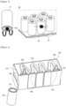
- Figure 1 is a diagram for explaining chain ignition upon ignition of a battery cell.
- a battery module (10) may comprise a plurality of battery cells (11) and a heat sink (12) attached to the battery cells (11).
- a vent part (11a) formed so that when gas or the like is generated therein, the gas can be discharged is often provided.
- the vent part (11a) is opened by the internal pressure of the battery cell (11), and flames are ejected to the outside of the battery cell (11).
- the heat sink (12) blocks the vent part (11a) of the battery cell upon ignition occurrence inside the battery cell (11).
- the vent part (11a) does not open, and as a result, the internal pressure of the battery cell (11) continuously increases, and the flames tear the side of the battery cell (11) and are ejected to the outside.
- a battery module comprising a plurality of battery cells having vent parts, and a heat sink disposed to face the vent parts and provided to dissipate heat from the plurality of battery cells.
- the vent part is normally maintained in a closed state, but when an event such as a thermal runaway of the battery cell occurs, it is opened in the case that gas or a flame is generated inside the battery cell, whereby it is configured so that the gas or flame is discharged to the outside of the battery cell.
- the vent part may be provided by a method of forming a notch or the like in a specific portion of the battery cell case so that the relevant specific portion is ruptured when the internal pressure of the battery cell increases.
- the plurality of battery cells is arranged so that the respective vent parts are disposed side by side while facing the same direction. In this case, the vent part of each battery cell is arranged to face the heat sink.
- the heat sink comprises a heat dissipation case having a metal material and a resinous material and having a flow path groove forming a cooling flow path through which cooling water flows, and a heat dissipation film disposed to face the vent parts and coupled to the heat dissipation case to surround the flow path groove.
- the heat dissipation case may comprise a metal layer and a resin layer provided on one side of the metal layer.
- two or more layers of the resin layer may be laminated, and the respective layers may be formed of the same or different resins.
- the resin layer may comprise a first resin layer provided on one side of the metal layer and a second resin layer provided on the other side of the metal layer.
- the first resin layer and the second resin layer may be formed of the same or different resin materials.
- the resin layer may comprise a first resin layer provided on one side of the metal layer and a second resin layer provided on the first resin layer.
- the first resin layer and the second resin layer may be formed of the same or different resin materials.
- the metal layer may comprise one or more selected from the group consisting of aluminum, stainless steel, and steel plate.
- the heat sink may further comprise an inflow port provided on one side of the flow path groove and an outflow port on the other side of the flow path groove.
- the inflow port and the outflow port may each have a port body with a hollow inside and a port protrusion part protruding outward from the port body.
- the port body may be inserted into the flow path groove, and the port protrusion part may be supported on the heat dissipation case.
- the port protrusion parts may each be coupled to an outer circumferential surface of the heat dissipation case.
- the heat sink may comprise a washer member disposed between the port protrusion part and the heat dissipation case.
- the heat sink may comprise a coupling member screw-coupled to the port body inside the flow path groove and a sealing member disposed between the coupling member and the heat dissipation case inside the flow path groove.
- the sealing member may be arranged to contact the heat dissipation case.
- the heat dissipation film may have a thickness of 10 ⁇ m to 300 ⁇ m.
- the heat dissipation case may have a thickness of 0.3mm to 20mm.
- the heat dissipation film may be a film that a polymer resin film is compressed on a metal film, where the metal film may be an aluminum film, and the polymer resin film may comprise one or more selected from the group consisting of polypropylene (PP), nylon, and polyethylene terephthalate (PET)-based resins.
- PP polypropylene
- PET polyethylene terephthalate
- a polypropylene (PP) film may be compressed on one side of the metal film and a nylon film may be compressed on the other side of the metal film.
- a polypropylene (PP) film may be compressed on one side of the metal film, and a nylon film and a polyethylene terephthalate film (PET) may be compressed on the other side of the metal film in a double layer form.
- PP polypropylene
- PET polyethylene terephthalate film
- the battery module related to one example of the present invention may have the following effects.
- the heat sink (120) is coupled to the plurality of battery cells (110) so that a partial region of the vent part (111) in the battery cell (110) is positioned to be overlapped on the cooling flow path (125).
- the heat sink (120) may be coupled to the battery cell (110) by an adhesive (130).
- the heat sink (120) may comprise a heat dissipation case (121), a heat dissipation film (124), an inflow port (128) and an outflow port (129).
- the heat sink (120) is coupled to the battery cell (110) to perform a function of dissipating heat from the battery cell (110).
- An inflow opening (126) and an outflow opening (127) are provided in the flow path groove (123).
- the inlet opening (126) may be provided at the front end (the upstream side when the cooling water flows) of the flow path groove (123), and the outflow opening (127) may be provided at the rear end (the downstream side when the cooling water flows) of the flow path groove (123) on the opposite side of the inflow opening (126).
- the heat dissipation case (121) is made of a composite material including metal.
- Figure 4 schematically illustrates a cross section of a composite material constituting a heat dissipation case
- Figure 5 schematically illustrates various examples of a heat dissipation case.
- Reference symbol M in Figure 5 shows a metal layer.
- the resin layer (121a, 121d) may be separately referred to as "a first resin layer (121a) and a second resin layer (121d)".
- the first resin layer (121a) and/or the second resin layer (121d) may each be bonded to the metal layer (121c) by an adhesive (121b).
- the first resin layer (121a) and the second resin layer (121d) may be provided on one side or both sides of the metal layer (121c) in various combinations.
- the heat dissipation film (124) is provided to be torn by the force that upon inside ignition of the battery cell (110), the vent part (111) of the battery cell (110) is opened, and simultaneously the vent part (111) pushes up the heat dissipation film (124).
- the pressure at which the vent part (111) is opened may be determined upon inside ignition.
- the pressure applied to the heat dissipation film (124) may be measured or calculated.
- the heat dissipation film (124) may be provided to be damaged according to the pressure applied while the vent part (111) is opened, and to this end, the thickness, material, or physical properties, and the like of the heat dissipation film (124) may be adjusted.
- Figure 7 is a schematic cross-sectional diagram for explaining one coupling structure of an inflow port and a heat sink
- Figure 8 is schematic diagrams showing a sealing member
- Figure 9 is a schematic cross-sectional diagram for explaining a coupling structure of an inflow port and a heat sink.
- Figure 10 is a diagram for explaining an operation in which cooling water is discharged from a heat sink upon inside ignition of a battery cell.
- the outflow port (129) is a passage through which the cooling water (W) is discharged from the cooling flow path (125).
- the outflow port (129) is coupled to the heat dissipation case (121) so as to communicate with the flow path groove (123) by penetrating the outflow opening (127).
- the outflow port (129) is coupled to the heat dissipation case (121) on the side opposite to the inflow port (128) along the longitudinal direction (L) of the heat dissipation case (121).
- the inflow port (128) and the outflow port (129) have the same structure. Accordingly, in this example, it will be described based on the inflow port (128).
- the sealing member (150) may be coupled to the port body (128a) on the inside of the flow path groove (123) to penetrate the lower end (128c) of the pot body between the inner surface of the heat dissipation case (121) and the coupling member (160).
- the sealing member (150) performs a function of sealing a gap between the heat dissipation case (121) and the pot body (128a).
- the sealing member (150) may be made of a material having predetermined elasticity.
- the inflow port (128) may be coupled so that the lower end (128c) of the port body penetrates the inflow opening (126), and thus the washer member (140) surrounds the inflow opening (126) on the outer circumferential surface of the heat dissipation case (121).
- the sealing protrusion (152) of the sealing member (150) contacts the inner surface of the heat dissipation case (121), and the coupling member (160) is screw-coupled to the lower end (128c) of the port body while being in contact with the reference surface (151) of the sealing member (150), whereby the inflow port (128) may be coupled to the heat dissipation case (121) on the inside of the flow path groove (123).
- the port protrusion part (128b) may be coupled to the outer surface of the heat dissipation case (121) by thermal fusion.
- the lower end (128c) of the port body may be coupled to the inner surface of the heat dissipation case (121) by the washer member (140) on the inside of the flow path groove (123).
- the washer member (140) may be coupled to the inner surface of the heat dissipation case (121) by an adhesive by penetrating the lower end (128c) of the pot body.
- the heat dissipation film (124) is torn by the force that upon inside ignition of the battery cell (110), the vent part (111) of the battery cell (110) is opened, and simultaneously the vent part (111) pushes up the heat dissipation film (124). At this time, the cooling water (W) flowing through the cooling flow path (125) flows down to the ignited battery cell (110).
- the present invention can secure the safety of the battery module (100) by early extinguishing the flame of the ignited battery cell (110) to suppress the temperature rise of the ignited battery cell (110) and the adjacent battery cells (110).
- the heat dissipation film opposing the vent part of the battery cell is torn by the pressure that the vent part of the battery cell is opened, and simultaneously the cooling water flowing inside the heat sink flows down to the battery cell, whereby it is possible to early extinguish the flame of the ignited battery cell.
Landscapes
- Chemical & Material Sciences (AREA)
- Chemical Kinetics & Catalysis (AREA)
- Electrochemistry (AREA)
- General Chemical & Material Sciences (AREA)
- Engineering & Computer Science (AREA)
- Manufacturing & Machinery (AREA)
- Health & Medical Sciences (AREA)
- Public Health (AREA)
- Business, Economics & Management (AREA)
- Emergency Management (AREA)
- Inorganic Chemistry (AREA)
- Battery Mounting, Suspending (AREA)
- Secondary Cells (AREA)
Abstract
Description
- The present invention relates to a battery module, and specifically, relates to a battery module capable of extinguishing flames as cooling water in a heat sink flows down into a battery cell upon inside ignition of the battery cell.
- This application claims the benefit of priority based on
Korean Patent Application No. 10-2022-0033660 dated March 17, 2022 - In a battery module according to the conventional art,
Figure 1 is a diagram for explaining chain ignition upon ignition of a battery cell. - Referring to
Figure 1 , a battery module (10) may comprise a plurality of battery cells (11) and a heat sink (12) attached to the battery cells (11). - Generally, in the case of a can-type battery cell (11), a vent part (11a) formed so that when gas or the like is generated therein, the gas can be discharged is often provided. When ignition occurs inside the battery cell (11), the vent part (11a) is opened by the internal pressure of the battery cell (11), and flames are ejected to the outside of the battery cell (11).
- Meanwhile, when the side of the vent part (11a) of the battery cell (11) is attached to the heat sink (12), the heat sink (12) blocks the vent part (11a) of the battery cell upon ignition occurrence inside the battery cell (11). In this case, upon ignition of the battery cell (11), the vent part (11a) does not open, and as a result, the internal pressure of the battery cell (11) continuously increases, and the flames tear the side of the battery cell (11) and are ejected to the outside.
- In this way, while the flames ejected to the side of the battery cell (11) are transferred to the adjacently disposed battery cells, there is a problem of causing chain ignition.
- It is a problem to be solved by the present invention to provide a battery module, wherein when a battery cell is ignited to open a vent part, cooling water in a heat sink flows down to the ignited battery cell while the heat sink is damaged, thereby being capable of early extinguishing flames of battery cells.
- Also, it is a problem to be solved by the present invention to provide a battery module, wherein when a vent part is opened, a heat dissipation film manufactured in the form of a thin film in micrometer units is provided to be tom.
- In addition, it is a problem to be solved by the present invention to provide a battery module capable of preventing side explosion of battery cells to prevent chain ignition of battery cells.
- In order to solve the above problems, according to one aspect of the present invention, a battery module comprising a plurality of battery cells having vent parts, and a heat sink disposed to face the vent parts and provided to dissipate heat from the plurality of battery cells is provided. The vent part is normally maintained in a closed state, but when an event such as a thermal runaway of the battery cell occurs, it is opened in the case that gas or a flame is generated inside the battery cell, whereby it is configured so that the gas or flame is discharged to the outside of the battery cell. The vent part may be provided by a method of forming a notch or the like in a specific portion of the battery cell case so that the relevant specific portion is ruptured when the internal pressure of the battery cell increases. The plurality of battery cells is arranged so that the respective vent parts are disposed side by side while facing the same direction. In this case, the vent part of each battery cell is arranged to face the heat sink.
- The heat sink comprises a heat dissipation case having a metal material and a resinous material and having a flow path groove forming a cooling flow path through which cooling water flows, and a heat dissipation film disposed to face the vent parts and coupled to the heat dissipation case to surround the flow path groove.
- Also, it may be provided so that upon inside ignition of the battery cell, the cooling water flowing through the cooling flow path flows into the battery cell while the heat dissipation film facing the vent part is damaged.
- In addition, the heat dissipation case may comprise a metal layer and a resin layer provided on one side of the metal layer.
- As one example, two or more layers of the resin layer may be laminated, and the respective layers may be formed of the same or different resins.
- As another example, the resin layer may comprise a first resin layer provided on one side of the metal layer and a second resin layer provided on the other side of the metal layer. At this instance, the first resin layer and the second resin layer may be formed of the same or different resin materials.
- As another example, the resin layer may comprise a first resin layer provided on one side of the metal layer and a second resin layer provided on the first resin layer. At this instance, the first resin layer and the second resin layer may be formed of the same or different resin materials.
- Also, the metal layer may comprise one or more selected from the group consisting of aluminum, stainless steel, and steel plate.
- In addition, the heat sink may further comprise an inflow port provided on one side of the flow path groove and an outflow port on the other side of the flow path groove.
- Furthermore, the inflow port and the outflow port may each have a port body with a hollow inside and a port protrusion part protruding outward from the port body. In addition, the port body may be inserted into the flow path groove, and the port protrusion part may be supported on the heat dissipation case.
- Also, in the inflow port and the outflow port, the port protrusion parts may each be coupled to an outer circumferential surface of the heat dissipation case.
- In addition, the heat sink may comprise a washer member disposed between the port protrusion part and the heat dissipation case.
- Furthermore, the heat sink may comprise a coupling member screw-coupled to the port body inside the flow path groove and a sealing member disposed between the coupling member and the heat dissipation case inside the flow path groove.
- Also, the sealing member may be arranged to contact the heat dissipation case.
- In addition, the heat dissipation case may be vacuum-molded so that the flow path groove is provided.
- Furthermore, the heat dissipation film may have a thickness of 10µm to 300µm.
- Also, the heat dissipation case may have a thickness of 0.3mm to 20mm.
- In addition, the heat dissipation film may be a film that a polymer resin film is compressed on a metal film, where the metal film may be an aluminum film, and the polymer resin film may comprise one or more selected from the group consisting of polypropylene (PP), nylon, and polyethylene terephthalate (PET)-based resins.
- As one example, in the heat dissipation film, a polypropylene (PP) film may be compressed on one side of the metal film and a nylon film may be compressed on the other side of the metal film.
- As another example, in the heat dissipation film, a polypropylene (PP) film may be compressed on one side of the metal film, and a nylon film and a polyethylene terephthalate film (PET) may be compressed on the other side of the metal film in a double layer form.
- As described above, the battery module related to one example of the present invention may have the following effects.
- As the heat dissipation film of the heat sink disposed to face the vent part of the battery cell is manufactured in the form of a thin film in micrometer units, the heat dissipation film is provided to be torn by the force that the internal pressure of the battery cell pushes the vent part upon inside ignition of the battery cell. As the vent part is smoothly opened while the heat dissipation film is damaged, it is possible to prevent side explosion of the battery cell, and it is possible to prevent chain ignition of the battery cell due to the side explosion of the battery cell.
- Also, upon inside ignition of the battery cell, the heat dissipation film facing the vent part of the battery cell is torn by the pressure that opens the vent part of the battery cell, and simultaneously the cooling water flowing inside the heat sink flows down to the battery cell, whereby it is possible to early extinguish the flame of the ignited battery cell.
- In addition, as the flame of the ignited battery cell is early extinguished to suppress the temperature rise of the ignited battery cell and the battery cells adjacent thereto, it is possible to secure the safety of the battery module.
- Furthermore, as the heat sink is made of a composite material including a metal material, it is possible to improve heat dissipation properties.
- In addition, compared to conventional heat sinks made of only resins, the heat dissipation case is made of a composite material including a resin material and a metal material, whereby it is possible to secure structural rigidity, and it is possible to promote the slimming of the heat sink.
-
-
Figure 1 is a diagram for explaining chain ignition upon ignition of a battery cell in a battery module according to the conventional art. -
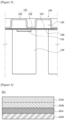
Figure 2 is a perspective diagram of a state where a partial region of a battery module according to one example of the present invention has been cut. -
Figure 3 is a cross-sectional diagram schematically showing a battery module according to one example of the present invention. -
Figure 4 schematically illustrates a cross section of a composite material constituting a heat dissipation case. -
Figure 5 schematically illustrates various examples of a heat dissipation case. -
Figure 6 schematically illustrates a cross section of a heat dissipation film. -
Figure 7 is a schematic cross-sectional diagram for explaining one coupling structure of an inflow port and a heat sink. -
Figure 8 is schematic diagrams showing a sealing member. -
Figure 9 is a schematic cross-sectional diagram for explaining a coupling structure of an inflow port and a heat sink. -
Figure 10 is a diagram for explaining an operation in which cooling water is discharged from a heat sink upon inside ignition of a battery cell. - Hereinafter, a battery module according to one example of the present invention will be described in detail with reference to the drawings.
- In addition, regardless of the reference numerals, the same or corresponding components are given by the same or similar reference numerals, duplicate descriptions thereof will be omitted, and for convenience of explanation, the size and shape of each component member as shown can be exaggerated or reduced.
-
Figure 2 is a perspective diagram of a state where a partial region of a battery module according to one example of the present invention has been cut, andFigure 3 is a cross-sectional diagram schematically showing a battery module according to one example of the present invention. - Referring to
Figure 2 , a battery module (100) according to one example of the present invention comprises a plurality of battery cells (110) and a heat sink (120). - Upon inside ignition of the battery cell (110), the heat dissipation film (124) of the heat sink (120) is torn by the pressure to open the vent part (111) of the battery cell (110), and simultaneously cooling water flows down to the battery cell (110) through the torn portion of the heat dissipation film. As a result, it is for preventing the continuous ignition of the battery cell (110) by early extinguishing the flame of the ignited battery cell (110).
- As one example, the battery cell (110) is a cylindrical battery cell (110), where an electrode assembly (positive electrode, negative electrode, separator, etc.) may be embedded therein. A vent part (111) is provided in the battery cell (110). Since the battery cell (110) is a well-known technology, the description thereof will be omitted in this example.
- Referring to
Figures 2 and3 , the heat sink (120) is coupled to the plurality of battery cells (110) so that a partial region of the vent part (111) in the battery cell (110) is positioned to be overlapped on the cooling flow path (125). In addition, the heat sink (120) may be coupled to the battery cell (110) by an adhesive (130). - At this time, the battery cell (110) is preferably coupled to the heat sink (120) such that an area located on a film coupling surface (122) is minimized. This is to allow the vent part (111) of the battery cell (110) to be opened more easily upon inside ignition of the battery cell (110).
- The heat sink (120) may comprise a heat dissipation case (121), a heat dissipation film (124), an inflow port (128) and an outflow port (129). The heat sink (120) is coupled to the battery cell (110) to perform a function of dissipating heat from the battery cell (110).
- The heat dissipation case (121) is combined with the heat dissipation film (124) to form a cooling flow path (125) through which cooling water flows. As one example, the heat dissipation case (121) is vacuum-molded so that the flow path groove (123) forming the cooling flow path (125) is provided.
- The heat dissipation case (121) may comprise a film coupling surface (122), a flow path groove (123), an inflow opening (126) and an outflow opening (127).
- The flow path groove (123) is provided stepwise with respect to the film coupling surface (122). The flow path groove (123) may be provided so that cooling water is flowable over the entire area of the heat dissipation case (121) in a zigzag shape. The flow path groove (123) guides the flow of cooling water from the inflow port (128) to the outflow port (129) along the longitudinal direction (L) of the heat dissipation case.
- An inflow opening (126) and an outflow opening (127) are provided in the flow path groove (123). The inlet opening (126) may be provided at the front end (the upstream side when the cooling water flows) of the flow path groove (123), and the outflow opening (127) may be provided at the rear end (the downstream side when the cooling water flows) of the flow path groove (123) on the opposite side of the inflow opening (126).
- In addition, the heat dissipation case (121) is made of a composite material including metal.
-
Figure 4 schematically illustrates a cross section of a composite material constituting a heat dissipation case, andFigure 5 schematically illustrates various examples of a heat dissipation case. Reference symbol M inFigure 5 shows a metal layer. - Referring to
Figure 4 , the composite material comprises a metal material, where the metal layer may be surface-treated with a resin material. As one example, the composite material comprises a metal layer (121c), a first resin layer (121a), and a second resin layer (121d). - The metal layer (121c) may comprise one or more selected from the group consisting of aluminum, stainless steel, or steel plate. In the metal layer (121c), at least one side of the metal layer (121c) is insulated by the resin layer (121a, 121d).
- The first resin layer (121a) may be provided on one side of the metal layer (121c). As one example, the first resin layer (121a) may comprise one or more selected from the group consisting of a polyvinyl chloride (PVC)-based resin, a polypropylene (PP)-based resin, and a polybutyl terephthalate (PBT)-based resin. In addition, the first resin layer (121a) may be bonded to the metal layer (121c) by an adhesive (121b).
- In addition, the resin layer (121a, 121d) may be formed in a multilayer structure in which two or more layers are laminated. As one example, the resin layer (121a, 121d) may be provided on one side of the metal layer as a double layer structure.
- The resin layer (121a, 121d) may be provided on both sides of the metal layer (121c), respectively. Alternatively, the resin layer (121a, 121d) may be provided on any one side of the metal layer (121c) in a laminated form, that is, in a double layer form.
- In this document, for convenience of description, the resin layer (121a, 121d) may be separately referred to as "a first resin layer (121a) and a second resin layer (121d)". The first resin layer (121a) and/or the second resin layer (121d) may each be bonded to the metal layer (121c) by an adhesive (121b).
- The first resin layer (121a) and the second resin layer (121d) may be formed of the same or different resin materials. As one example, the first resin layer (121a) and the second resin layer (121d) may each comprise one or more selected from the group consisting of a PVC-based resin, a PP-based resin, and a PBT-based resin.
- The PVC (polyvinyl chloride)-based resin is inexpensive. The PP (poly propylene)-based resin has excellent chemical resistance and balance. The PBT (polybutylene terephthalate)-based resin has excellent heat resistance. Depending on the intended use of the composite material, the types of resins are variable in various ways.
- Referring to
Figure 5 , the first resin layer (121a) and the second resin layer (121d) may be provided on one side or both sides of the metal layer (121c) in various combinations. - The first resin layer (121a) may be a double layer in which one side is provided with any one of the PVC-based resin, PP-based resin, and PBT-based resin, and the other side is provided with another resin. For example, when the PVC-based resin constitutes one side of the first resin layer (121a) and the PP-based resin constitutes the other side of the first resin layer (121a), the molecular structure of the PVC-based resin and the molecular structure of the PP-based resin are different from each other, whereby the first resin layer (121a) can prevent pinholes.
- The second resin layer (121d) may be provided on the other side of the metal layer (121c). The second resin layer (121d) comprises one or more selected from the group consisting of a PVC-based resin, a PP-based resin, and a PBT-based resin.
- The second resin layer (121d) may have a double layer in which any one of the PVC-based resin, PP-based resin, and PBT-based resin constitutes one side and another resin constitutes the other side.
- In such a structure, the heat dissipation case (121) may have structural rigidity and heat dissipation due to the metal layer (121c), and may secure insulation properties due to the first resin layer (121a) and the second resin layer (121d).
-
Figure 6 schematically illustrates a cross section of a heat dissipation film. - The heat dissipation film (124) is a thin film. The heat dissipation film (124) has a thickness ranging from 10µm to 990µm. The heat dissipation film (124) has heat dissipation and insulation properties.
- The heat dissipation film (124) is provided to be torn by the force that upon inside ignition of the battery cell (110), the vent part (111) of the battery cell (110) is opened, and simultaneously the vent part (111) pushes up the heat dissipation film (124). Depending on the specification and size of the battery cell (110), the structure of the vent part (111), and the like, the pressure at which the vent part (111) is opened may be determined upon inside ignition. Similarly, when the vent part (111) is opened, the pressure applied to the heat dissipation film (124) may be measured or calculated. The heat dissipation film (124) may be provided to be damaged according to the pressure applied while the vent part (111) is opened, and to this end, the thickness, material, or physical properties, and the like of the heat dissipation film (124) may be adjusted.
- As one example, the heat dissipation film (124) may be a film that a polymer resin film is compressed on a metal film. The metal film may comprise an aluminum film. Referring to
Figure 6 , the heat dissipation film (124) is a film that a polypropylene (PP) film (124a), an aluminum film (124b), a nylon film (124c), and a polyethylene terephthalate (PET) film (124d) are laminated and compressed. - The heat dissipation film (124) may be coupled to the film coupling surface (122) of the heat dissipation case (121) in a thermal compression method. The heat dissipation film (124) may be coupled to the film coupling surface (122) to cover the flow path groove (123), thereby forming a cooling flow path (125).
-
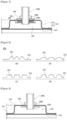
Figure 7 is a schematic cross-sectional diagram for explaining one coupling structure of an inflow port and a heat sink,Figure 8 is schematic diagrams showing a sealing member, andFigure 9 is a schematic cross-sectional diagram for explaining a coupling structure of an inflow port and a heat sink. - Also,
Figure 10 is a diagram for explaining an operation in which cooling water is discharged from a heat sink upon inside ignition of a battery cell. - The inflow port (128) is a passage through which the cooling water (W) flows into the cooling flow path (125). The inflow port (128) is coupled to the heat dissipation case (121) so as to communicate with the flow path groove (123) by penetrating the inflow opening (126).
- The outflow port (129) is a passage through which the cooling water (W) is discharged from the cooling flow path (125). The outflow port (129) is coupled to the heat dissipation case (121) so as to communicate with the flow path groove (123) by penetrating the outflow opening (127). The outflow port (129) is coupled to the heat dissipation case (121) on the side opposite to the inflow port (128) along the longitudinal direction (L) of the heat dissipation case (121).
- The inflow port (128) and the outflow port (129) have the same structure. Accordingly, in this example, it will be described based on the inflow port (128).
- The inflow port (128) comprises a port body (128a) and a port protrusion part (128b).
- The port body (128a) has a form with a hollow inside. The port protrusion part (128b) is provided at the lower end (128c) of the port body. The port protrusion part (128b) is provided to protrude outward from the port body (128a). The port protrusion part (128b) may be integrally provided with the port body (128a).
- The inflow port (128) may be coupled to the heat dissipation case so that the lower end (128c) of the port body is inserted into the flow path groove (123) by passing through the inflow opening (126), and the port protrusion part (128b) is caught on the outer surface of the heat dissipation case (121).
- As one example, referring to
Figure 7 , the inflow port (128) may be coupled to the heat dissipation case (121) through a washer member (140), a sealing member (150), and a coupling member (160). - Also, the washer member (140) may be installed between the heat dissipation case (121) and the port protrusion part (128b) so that the port protrusion part (128b) is caught by penetrating the lower end (128c) of the port body.
- In addition, the sealing member (150) may be coupled to the port body (128a) on the inside of the flow path groove (123) to penetrate the lower end (128c) of the pot body between the inner surface of the heat dissipation case (121) and the coupling member (160). The sealing member (150) performs a function of sealing a gap between the heat dissipation case (121) and the pot body (128a). The sealing member (150) may be made of a material having predetermined elasticity.
- Referring to
Figure 8 , the sealing member (150) may have a plurality of sealing protrusions (152) protruding from the reference surface (151). The sealing protrusion (152) may have any one of a triangular section, a quadrangular section, a semicircular section, a loud section, or a sharp polygonal section. - Referring to
Figure 7 , the coupling member (160) penetrates the lower end (128c) of the port body on the inside of the flow path groove (123), but may be screw-coupled along a screw thread provided at the lower end (128c) of the port body. - Also, in a state where the washer member (140) is fitted to the lower end (128c) of the port body so as to be caught by the port protrusion part (128b), the inflow port (128) may be coupled so that the lower end (128c) of the port body penetrates the inflow opening (126), and thus the washer member (140) surrounds the inflow opening (126) on the outer circumferential surface of the heat dissipation case (121).
- In addition, the sealing protrusion (152) of the sealing member (150) contacts the inner surface of the heat dissipation case (121), and the coupling member (160) is screw-coupled to the lower end (128c) of the port body while being in contact with the reference surface (151) of the sealing member (150), whereby the inflow port (128) may be coupled to the heat dissipation case (121) on the inside of the flow path groove (123).
- As another example, referring to
Figure 9 , the port protrusion part (128b) may be coupled to the outer surface of the heat dissipation case (121) by thermal fusion. In addition, the lower end (128c) of the port body may be coupled to the inner surface of the heat dissipation case (121) by the washer member (140) on the inside of the flow path groove (123). The washer member (140) may be coupled to the inner surface of the heat dissipation case (121) by an adhesive by penetrating the lower end (128c) of the pot body. - Referring to
Figure 10 , the heat dissipation film (124) is torn by the force that upon inside ignition of the battery cell (110), the vent part (111) of the battery cell (110) is opened, and simultaneously the vent part (111) pushes up the heat dissipation film (124). At this time, the cooling water (W) flowing through the cooling flow path (125) flows down to the ignited battery cell (110). - Accordingly, the present invention can secure the safety of the battery module (100) by early extinguishing the flame of the ignited battery cell (110) to suppress the temperature rise of the ignited battery cell (110) and the adjacent battery cells (110).
- The preferred examples of the present invention as described above have been disclosed for illustrative purposes, and those skilled in the art having ordinary knowledge of the present invention will be able to make various modifications, changes, and additions within the spirit and scope of the present invention, and such modifications, changes, and additions should be regarded as falling within the scope of the following claims.
- According to the battery module in accordance with one example of the present invention, upon inside ignition of the battery cell, the heat dissipation film opposing the vent part of the battery cell is torn by the pressure that the vent part of the battery cell is opened, and simultaneously the cooling water flowing inside the heat sink flows down to the battery cell, whereby it is possible to early extinguish the flame of the ignited battery cell.
Claims (15)
- A battery module comprising: a plurality of battery cells having vent parts; anda heat sink disposed to face the vent parts and provided to dissipate heat from the plurality of battery cells, whereinthe heat sink comprises a heat dissipation case having a metal material and a resinous material and having a flow path groove forming a cooling flow path through which cooling water flows, and a heat dissipation film disposed to face the vent parts and coupled to the heat dissipation case to surround the flow path groove.
- The battery module according to claim 1, provided so that
upon inside ignition of the battery cell, the cooling water flowing through the cooling flow path flows into the battery cell while the heat dissipation film facing the vent part is damaged. - The battery module according to claim 1, whereinthe heat dissipation case comprises a metal layer; anda resin layer provided on one side of the metal layer.
- The battery module according to claim 3, whereintwo or more layers of the resin layer are laminated, andthe respective layers are formed of the same or different resins.
- The battery module according to claim 3, wherein the resin layer comprisesa first resin layer provided on one side of the metal layer and a second resin layer provided on the other side of the metal layer, andthe first resin layer and the second resin layer are formed of the same or different resin materials.
- The battery module according to claim 3, wherein the resin layer comprisesa first resin layer provided on one side of the metal layer and a second resin layer provided on the first resin layer, andthe first resin layer and the second resin layer are formed of the same or different resin materials.
- The battery module according to claim 3, wherein
the metal layer comprises one or more selected from the group consisting of aluminum, stainless steel, and steel plate. - The battery module according to claim 1, wherein
the heat sink further comprises an inflow port provided on one side of the flow path groove and an outflow port on the other side of the flow path groove. - The battery module according to claim 8, whereinthe inflow port and the outflow port each have a port body with a hollow inside and a port protrusion part protruding outward from the port body, andthe port body is inserted into the flow path groove, and the port protrusion part is supported on the heat dissipation case.
- The battery module according to claim 9, wherein
in the inflow port and the outflow port, the port protrusion parts are each coupled to an outer circumferential surface of the heat dissipation case. - The battery module according to claim 10, further comprising
a washer member disposed between the port protrusion part and the heat dissipation case. - The battery module according to claim 11, further comprising
a coupling member screw-coupled to the port body inside the flow path groove, and a sealing member disposed between the coupling member and the heat dissipation case inside the flow path groove. - The battery module according to claim 12, wherein
the sealing member has a plurality of sealing protrusions arranged to contact the heat dissipation case. - The battery module according to claim 1, wherein
the heat dissipation case is vacuum-molded so that the flow path groove is provided. - The battery module according to claim 1, whereinthe heat dissipation film has a thickness of 10µm to 300µm, andthe heat dissipation case has a thickness of 0.3mm to 20mm.
Applications Claiming Priority (2)
| Application Number | Priority Date | Filing Date | Title |
|---|---|---|---|
| KR1020220033660A KR20230135998A (en) | 2022-03-17 | 2022-03-17 | Heat sink, manufacturing method thereof, and battery module |
| PCT/KR2023/003435 WO2023177196A1 (en) | 2022-03-17 | 2023-03-15 | Battery module |
Publications (2)
| Publication Number | Publication Date |
|---|---|
| EP4395011A1 true EP4395011A1 (en) | 2024-07-03 |
| EP4395011A4 EP4395011A4 (en) | 2025-01-29 |
Family
ID=88024043
Family Applications (1)
| Application Number | Title | Priority Date | Filing Date |
|---|---|---|---|
| EP23771075.1A Pending EP4395011A4 (en) | 2022-03-17 | 2023-03-15 | Battery module |
Country Status (6)
| Country | Link |
|---|---|
| US (1) | US20250140964A1 (en) |
| EP (1) | EP4395011A4 (en) |
| JP (1) | JP7668418B2 (en) |
| KR (1) | KR20230135998A (en) |
| CN (1) | CN118056315A (en) |
| WO (1) | WO2023177196A1 (en) |
Family Cites Families (14)
| Publication number | Priority date | Publication date | Assignee | Title |
|---|---|---|---|---|
| US9093726B2 (en) | 2009-09-12 | 2015-07-28 | Tesla Motors, Inc. | Active thermal runaway mitigation system for use within a battery pack |
| JP2013131428A (en) | 2011-12-22 | 2013-07-04 | Panasonic Corp | Battery with cooling part |
| KR101446956B1 (en) * | 2012-12-13 | 2014-11-04 | 대한칼소닉주식회사 | Battery heat sink having structure stacked fluid path |
| US9912021B2 (en) * | 2013-05-17 | 2018-03-06 | Hamilton Sundstrand Corporation | Electrical storage device thermal management systems |
| KR102445835B1 (en) | 2017-10-13 | 2022-09-20 | 에스케이온 주식회사 | Battery module with fire extinguishing device |
| KR102523702B1 (en) * | 2018-07-03 | 2023-04-19 | 주식회사 엘지에너지솔루션 | Battery module |
| KR102330377B1 (en) * | 2018-10-12 | 2021-11-22 | 주식회사 엘지에너지솔루션 | Battery module, battery rack comprising the battery module, and energy storage system comprising the battery rack |
| JP2020088108A (en) * | 2018-11-21 | 2020-06-04 | 三井化学株式会社 | Cooler and structure |
| JP7381247B2 (en) * | 2019-08-09 | 2023-11-15 | 株式会社レゾナック・パッケージング | Heat exchange module and heat exchange equipment |
| KR102825129B1 (en) * | 2020-06-02 | 2025-06-24 | 주식회사 엘지에너지솔루션 | Battery module configured to multiple cooling, battery pack and vehicle comprising the same |
| KR102690299B1 (en) * | 2020-06-29 | 2024-08-01 | 주식회사 엘지에너지솔루션 | Battery Module Comprising Heat Dissipation Member and Method for Preparing the Heat Dissipation Member |
| ES2943267T3 (en) * | 2020-07-10 | 2023-06-12 | Contemporary Amperex Technology Co Ltd | battery and electrical device |
| CN212700167U (en) * | 2020-07-16 | 2021-03-16 | 哲弗智能系统(上海)有限公司 | Passive fire extinguishing device and battery pack |
| KR20220033660A (en) | 2020-09-09 | 2022-03-17 | 주식회사 팝스라인 | System for augmented reality-based celebrity calling event and method thereof |
-
2022
- 2022-03-17 KR KR1020220033660A patent/KR20230135998A/en active Pending
-
2023
- 2023-03-15 US US18/693,668 patent/US20250140964A1/en active Pending
- 2023-03-15 WO PCT/KR2023/003435 patent/WO2023177196A1/en not_active Ceased
- 2023-03-15 EP EP23771075.1A patent/EP4395011A4/en active Pending
- 2023-03-15 CN CN202380013903.0A patent/CN118056315A/en active Pending
- 2023-03-15 JP JP2024516954A patent/JP7668418B2/en active Active
Also Published As
| Publication number | Publication date |
|---|---|
| JP7668418B2 (en) | 2025-04-24 |
| KR20230135998A (en) | 2023-09-26 |
| US20250140964A1 (en) | 2025-05-01 |
| CN118056315A (en) | 2024-05-17 |
| WO2023177196A1 (en) | 2023-09-21 |
| JP2024534451A (en) | 2024-09-20 |
| EP4395011A4 (en) | 2025-01-29 |
Similar Documents
| Publication | Publication Date | Title |
|---|---|---|
| EP4009432B1 (en) | Pouch-shaped battery cell having venting portion attached thereto and method of manufacturing the same | |
| JP6452059B2 (en) | Pouch-type secondary battery including electrode lead with current limiting function | |
| JP7546932B2 (en) | Sealing film, tab lead and secondary battery using same | |
| US20100291423A1 (en) | Electric storage device | |
| US20230361378A1 (en) | Cooling device, battery module and energy storage system and vehicle comprising the battery module | |
| KR102341465B1 (en) | The Apparatus For Venting And The Method For Manufacturing Thereof | |
| KR20170046725A (en) | Packaging material for battery | |
| KR20240076787A (en) | Adhesive film, method for producing adhesive film, power storage device, and method for producing power storage device | |
| WO2021246177A1 (en) | Sealing film, and tab lead and secondary battery which use same | |
| KR20220163090A (en) | Pouch-type battery cell comprising sealing-part venting control means | |
| JP2004327047A (en) | Polymer battery and polymer battery pack | |
| US20250140964A1 (en) | Battery Module | |
| JP4069565B2 (en) | Sealed battery | |
| JP5926643B2 (en) | Container with lid | |
| KR101460637B1 (en) | Sealant for, and battery using the same | |
| JP5673135B2 (en) | Laminated battery | |
| KR20200024808A (en) | Outer casing material for battery and battery | |
| US20240120610A1 (en) | Module cover for a battery module, battery module and method for producing a module cover | |
| EP4366064A1 (en) | Battery module and manufacturing method thereof | |
| JP5786344B2 (en) | Packaging bag | |
| KR20090079020A (en) | Laminate sheet for secondary battery package and secondary battery comprising same | |
| JP2001229911A (en) | Sealed battery | |
| CN218731170U (en) | Aluminum-plastic composite film capable of reducing glue overflow | |
| KR102964089B1 (en) | Battery module and method thereof | |
| JP6469759B2 (en) | battery |
Legal Events
| Date | Code | Title | Description |
|---|---|---|---|
| STAA | Information on the status of an ep patent application or granted ep patent |
Free format text: STATUS: THE INTERNATIONAL PUBLICATION HAS BEEN MADE |
|
| PUAI | Public reference made under article 153(3) epc to a published international application that has entered the european phase |
Free format text: ORIGINAL CODE: 0009012 |
|
| STAA | Information on the status of an ep patent application or granted ep patent |
Free format text: STATUS: REQUEST FOR EXAMINATION WAS MADE |
|
| 17P | Request for examination filed |
Effective date: 20240325 |
|
| AK | Designated contracting states |
Kind code of ref document: A1 Designated state(s): AL AT BE BG CH CY CZ DE DK EE ES FI FR GB GR HR HU IE IS IT LI LT LU LV MC ME MK MT NL NO PL PT RO RS SE SI SK SM TR |
|
| REG | Reference to a national code |
Ref country code: DE Ref legal event code: R079 Free format text: PREVIOUS MAIN CLASS: H01M0010655100 Ipc: A62C0003160000 |
|
| A4 | Supplementary search report drawn up and despatched |
Effective date: 20250107 |
|
| RIC1 | Information provided on ipc code assigned before grant |
Ipc: H01M 10/647 20140101ALI20241220BHEP Ipc: H01M 10/625 20140101ALI20241220BHEP Ipc: H01M 10/6554 20140101ALI20241220BHEP Ipc: H01M 50/224 20210101ALI20241220BHEP Ipc: H01M 50/30 20210101ALI20241220BHEP Ipc: H01M 50/383 20210101ALI20241220BHEP Ipc: H01M 50/375 20210101ALI20241220BHEP Ipc: H01M 50/342 20210101ALI20241220BHEP Ipc: H01M 50/213 20210101ALI20241220BHEP Ipc: H01M 10/42 20060101ALI20241220BHEP Ipc: H01M 10/613 20140101ALI20241220BHEP Ipc: H01M 10/6567 20140101ALI20241220BHEP Ipc: H01M 10/653 20140101ALI20241220BHEP Ipc: H01M 10/6556 20140101ALI20241220BHEP Ipc: H01M 10/6551 20140101ALI20241220BHEP Ipc: A62C 35/10 20060101ALI20241220BHEP Ipc: A62C 3/16 20060101AFI20241220BHEP |
|
| STAA | Information on the status of an ep patent application or granted ep patent |
Free format text: STATUS: EXAMINATION IS IN PROGRESS |
|
| DAV | Request for validation of the european patent (deleted) | ||
| DAX | Request for extension of the european patent (deleted) | ||
| 17Q | First examination report despatched |
Effective date: 20250603 |
|
| GRAP | Despatch of communication of intention to grant a patent |
Free format text: ORIGINAL CODE: EPIDOSNIGR1 |
|
| STAA | Information on the status of an ep patent application or granted ep patent |
Free format text: STATUS: GRANT OF PATENT IS INTENDED |
|
| INTG | Intention to grant announced |
Effective date: 20251211 |
|
| P01 | Opt-out of the competence of the unified patent court (upc) registered |
Free format text: CASE NUMBER: UPC_APP_0000293_4395011/2026 Effective date: 20260106 |
|
| GRAS | Grant fee paid |
Free format text: ORIGINAL CODE: EPIDOSNIGR3 |
|
| GRAA | (expected) grant |
Free format text: ORIGINAL CODE: 0009210 |
|
| STAA | Information on the status of an ep patent application or granted ep patent |
Free format text: STATUS: THE PATENT HAS BEEN GRANTED |