EP4394805A1 - Transposed electrical conductor and bushing - Google Patents
Transposed electrical conductor and bushing Download PDFInfo
- Publication number
- EP4394805A1 EP4394805A1 EP22217101.9A EP22217101A EP4394805A1 EP 4394805 A1 EP4394805 A1 EP 4394805A1 EP 22217101 A EP22217101 A EP 22217101A EP 4394805 A1 EP4394805 A1 EP 4394805A1
- Authority
- EP
- European Patent Office
- Prior art keywords
- conductor
- partial
- electrical
- electrical conductor
- transposed
- Prior art date
- Legal status (The legal status is an assumption and is not a legal conclusion. Google has not performed a legal analysis and makes no representation as to the accuracy of the status listed.)
- Pending
Links
Images


Classifications
-
- H—ELECTRICITY
- H01—ELECTRIC ELEMENTS
- H01B—CABLES; CONDUCTORS; INSULATORS; SELECTION OF MATERIALS FOR THEIR CONDUCTIVE, INSULATING OR DIELECTRIC PROPERTIES
- H01B7/00—Insulated conductors or cables characterised by their form
- H01B7/30—Insulated conductors or cables characterised by their form with arrangements for reducing conductor losses when carrying alternating current, e.g. due to skin effect
- H01B7/306—Transposed conductors
-
- H—ELECTRICITY
- H01—ELECTRIC ELEMENTS
- H01B—CABLES; CONDUCTORS; INSULATORS; SELECTION OF MATERIALS FOR THEIR CONDUCTIVE, INSULATING OR DIELECTRIC PROPERTIES
- H01B9/00—Power cables
- H01B9/04—Concentric cables
-
- H—ELECTRICITY
- H01—ELECTRIC ELEMENTS
- H01B—CABLES; CONDUCTORS; INSULATORS; SELECTION OF MATERIALS FOR THEIR CONDUCTIVE, INSULATING OR DIELECTRIC PROPERTIES
- H01B11/00—Communication cables or conductors
- H01B11/18—Coaxial cables; Analogous cables having more than one inner conductor within a common outer conductor
- H01B11/1895—Particular features or applications
Definitions
- a shell of the hollow cylinder is formed by the corresponding partial conductor, in particular the second partial conductor.
- the shell of the hollow cylinder comprises, exemplarily, an inner side surface corresponding to the inner radius and an outer side surface corresponding to the outer radius.
- the inner side surface and the outer side surface extend along the common cylinder axis, in particular completely, along the height.
- the inner side surface faces the common cylinder axis and the outer side surfaces faces away from the common cylinder axis.
- the inner side surface and the outer side surface surround the common cylinder axis in particular completely thereby enclosing a hollow space.
- the shell of the second partial conductor completely surrounds the first partial conductor, for example.
- an outer side surface of the first partial conductor faces the inner side surface of the second partial conductor.
- the first electrical conductor and the second electrical conductor are electrically connected by a junction.
- the junction is configured to transmit the electric current from the first electric conductor to the second electric conductor.
- the junction comprises an electrical conducting material.
- the electrical conducting material comprises or consists of a non-magnetic metal, such as at least one of the following materials: copper, aluminium, aluminium alloy.
- the junction can be the same material than the electrical conductors or can comprises or consists of a different material than the electrical conductors.
- Each of the partial conductors of the transposed electrical conductor is configured to transmit an alternating electric current, AC, and/or a direct electric current, DC, with an AC component.
- such a method can provide, inter alia, the following advantages.
- a thickness of the second partial conductor being at most 90 % of the corresponding skin depth
- current ratings can be increased with respect to conventional transposed electrical conductors having typically larger wall thicknesses.
- a second partial conductor with a thickness being at most 90 % of the corresponding skin depth - by having the same current ratings of a conventional transposed electrical conductor - can have a smaller size due to the reduced thickness. This advantageously reduces material costs.
- a replacement of partial conductors formed of copper by aluminium without changing a diameter can be performed.
- each of the two electrical conductors comprises at least two partial conductors which are electrically insulated from each other.
- the partial conductors are typically made as a concentric arrangement, so that there is an innermost partial conductor being the first partial conductor, and an outermost partial conductor being the second partial conductor.
- the junction commutes the currents of the partial conductors, so that the current from the innermost partial conductor of the first conductor flows to the outermost partial conductor of the second conductor and the current from the outermost partial conductor of the first conductor flows to the innermost partial conductor of the second conductor.
- all the partial conductors are electrically connected with each other, so that the total current flowing into the transposed conductor can be divided between all the partial conductors.
- junctions and the electrical conductors are arranged exemplarily in such a way that the current, when flowing from one end of the transposed electrical conductor to its other end, flows an approximately same distance through differently positioned partial conductors.
- the current flowing into the innermost partial conductor of the first electrical conductor commutes to the outermost partial conductor of the second electrical conductor and vice versa.
- the part of the current entering the innermost partial conductor at the first end flows a half of the length of the transposed electrical conductor through the innermost partial conductor and another half of the length through the outermost partial conductor.
- the total current flowing through the transposed electrical conductor is divided into two approximately equal parts, one current path comprising the innermost partial conductor of the first electrical conductor and the outermost partial conductor of the second electrical conductor, and the second path vice versa.
- transposed electrical conductor described herein approximately 30 % more current can be transmitted with respect to conventional transposed electrical conductors due to the specified wall thicknesses. Further, an overload capability of transposed electrical conductors described herein is further improved.
- thicknesses of more than 90 % of the corresponding skin depth lead to a significant increase of the losses, and at the same time to an increase of the material weight and consumption.
- the first partial conductor is a solid cylinder.
- the solid cylinder does not have a hollow space.
- the solid cylinder is a bulk cylinder.
- the solid cylinder is defined by a radius and a height.
- the height of the solid cylinder corresponds to the length of the first partial conductor, wherein the height extends along the common cylinder axis.
- the solid cylinder further comprises a first base and a second base being arranged opposite to one another along the common cylinder axis.
- the first base and the second base are perpendicular to the common cylinder axis.
- the first partial conductor can deviate from a shape of a solid cylinder due to production tolerances. This is to say that a cross section perpendicular to the common cylinder axis of the first partial conductor is approximately circular.
- a bulk of the solid cylinder is formed by the first partial conductor, comprising an outer side surface corresponding to the radius.
- the outer side surface of the solid cylinder extends along the common cylinder axis, in particular completely, along the height.
- the outer side surface of the solid cylinder of the first partial conductor faces the inner side surface of the hollow cylinder of the second partial conductor.
- the outer side surface of the solid cylinder of the first partial conductor is spaced apart in radial direction from the inner side surface of the hollow cylinder of the second partial conductor by a first gap.
- the first partial conductor is a hollow cylinder.
- the outer side surface of the hollow cylinder of the first partial conductor faces the inner side surface of the hollow cylinder of the second partial conductor.
- the outer side surface of the hollow cylinder of the first partial conductor is spaced apart in radial direction from the inner side surface of the hollow cylinder of the second partial conductor by the first gap.
- the first gap is, exemplarily, configured to electrically insulate the first partial conductor from the second partial conductor.
- the first gap can comprise an electrically insulating material.
- the electrically insulating material is completely arranged in the first gap.
- the first electrical conductor and the second electrical conductor have approximately the same length.
- approximately the same length means here and in the following that the electrical conductors, in particular all electrical conductors, have the same length, wherein the lengths do not deviate by more than 1 % from one another. Due to such lengths, a current distribution within each of the electrical conductors is equal to one another.
- An AC resistance can be calculated for a virtual second partial conductor being a hollow cylinder dependent on a thickness of the virtual second partial conductor.
- the calculated AC resistance has, exemplarily, a local minimum.
- the minimum in AC resistance corresponds to a thickness of the virtual second partial conductor of around 80 % of the skin depth.
- Such a thickness of the virtual second partial conductor is, exemplarily, equivalent to an AC resistance factor of the virtual second partial conductor of less than around 1.3.
- the AC resistance factor is understood as a ratio of losses of the AC current flowing within a partial conductor and losses of a DC current of the magnitude equal to the effective magnitude of that AC current and flowing within that partial conductor.
- the results concerning the calculated virtual second partial conductor can be applied one to one to the second partial conductor. In this way significant gain in decreasing of the losses can be obtained in a transposed electrical conductor advantageously having a reduced mass and a reduced material consumption.
- the thickness of the second partial conductor is at least 50 % of the skin depth at the operating frequency of the transposed electrical conductor.
- an application of a smaller thickness of the second partial conductor when maintaining the same cross section area of the second partial conductor, requires an increase of the outer diameter of the conductor.
- the benefits from the very slightly lower AC-resistance factor do not compensate disadvantages related to an increase of the diameter, of the material consumption and of the mass for the whole transposed electrical conductor.
- the thickness of the second partial conductor being at least 50 %, the above listed disadvantages are advantageously mitigated.
- the AC losses are advantageously surprisingly low in combination with saving material costs.
- the innermost, i.e. the first partial conductor, the intermediate, i.e. the second partial conductor, and the outermost partial conductor, i.e. the third partial conductor consists of at least three electrical conductors of approximately equal length and two junctions connecting the electrical conductors.
- three current paths are formed, one comprising the innermost partial conductor of the first electrical conductor, the intermediate partial conductor of the second electrical conductor, and the outermost partial conductor of the third electrical conductor.
- the other two current paths comprise the two different permutations of the partial conductors.
- the current is divided into three approximately equal parts, so that approximately one third of the current flows through each of the current paths.
- the third partial conductor is a hollow cylinder, and the second partial conductor is arranged within the hollow cylinder of the third partial conductor.
- a shell of the third partial conductor completely surrounds the first partial conductor and the second partial conductor, for example.
- the outer side surface of the second partial conductor faces an inner side surface of the third partial conductor.
- the outer side surface of the second partial conductor is spaced apart in radial direction from the inner side surface of the third partial conductor by a second gap.
- the second gap is, exemplarily, configured to electrically insulate the second partial conductor from the third partial conductor.
- the second gap can comprise the electrically insulating material.
- the electrically insulating material is completely arranged in the second gap.
- the AC losses are advantageously surprisingly low in combination with saving material costs.
- a transposed electrical conductor comprising four electrical conductors each comprising four partial conductors and being connected by three junctions, typically four current paths are formed and approximately one fourth of the total current flows through each of the parts.
- additional losses caused by the proximity effect in the second partial conductor are generated by the current flowing in the innermost partial conductor, i.e., by a current which is approximately equal to the value of its own current.
- the additional losses in the third partial conductor are generated by a current which is approximately twice the value of its own current.
- the additional losses are generated by a current of approximately three times the value of its own current. Because of that, the contribution of those additional losses are the larger, the more outer position of the partial conductor is. However, such losses are additionally reduced with the proposed thicknesses of the partial conductors.
- the fourth partial conductor is a hollow cylinder
- the third partial conductor is arranged within the hollow cylinder of the fourth partial conductor.
- a shell of the fourth partial conductor completely surrounds the first partial conductor, the second partial conductor and the third partial conductor, for example.
- an outer side surface of the third partial conductor faces an inner side surface of the fourth partial conductor.
- the outer side surface of the third partial conductor is spaced apart in radial direction from the inner side surface of the fourth partial conductor by a third gap.
- the third gap is, exemplarily, configured to electrically insulate the third partial conductor from the fourth partial conductor.
- the third gap can comprise the electrically insulating material.
- the electrically insulating material is completely arranged in the third gap.
- the junction electrically connects the first partial conductor of the first electrical conductor to the second partial conductor of the second electrical conductor, the junction electrically connects the second partial conductor of the first electrical conductor to the third partial conductor of the second electrical conductor, and the junction electrically connects the third partial conductor of the first electrical conductor to the first partial conductor of the second electrical conductor.
- the junction electrically connects the first partial conductor of the first electrical conductor to the second partial conductor of the second electrical conductor, the junction electrically connects the second partial conductor of the first electrical conductor to the third partial conductor of the second electrical conductor, the junction electrically connects the third partial conductor of the first electrical conductor to the fourth partial conductor of the second electrical conductor, and the junction electrically connects the fourth partial conductor of the first electrical conductor to the first partial conductor of the second electrical conductor.
- the junction has four parts, for example.
- a first part of the junction electrically connects the first partial conductor of the first electrical conductor to the second partial conductor of the second electrical conductor
- a second part of the junction electrically connects the second partial conductor of the first electrical conductor to the third partial conductor of the second electrical conductor
- a third part of the junction electrically connects the third partial conductor of the first electrical conductor to the fourth partial conductor of the second electrical conductor
- a fourth part of the junction electrically connects the fourth partial conductor of the first electrical conductor to the first partial conductor of the second electrical conductor.
- a transposing portion of each part has a length along the main extension direction of at most 300 % and/or at least 30 % of the skin depth at an operating frequency of the transposed electrical conductor.
- each part of the junction is, for example, a portion of the junction which leads the current form a radial position of one of the partial conductors to a radial position of the respective outer or respective inner partial conductor.
- the transposing portion is the portion of the junction through which the current flows in a substantially radial direction from a radial position of one of the partial conductors to a radial position of the respective outer or respective inner partial conductor, and thus the transposing portion has a length along the common cylinder axis.
- the length of the transposing portion is the length of the portion of the element of the junction, wherein the very part where the current commutes from the more outer to the more inner layer of the partial conductor.
- a further embodiment relates to a bushing with a transposed electrical conductor described herein above. Therefore, the features as described in connection with the transposed electrical conductor are also applicable for the bushing and vice versa.
- the transposed electrical conductor 2 according to the exemplary embodiment of Figure 1 comprises two electrical conductors 1, in particular a first electrical conductor 6 and a second electrical conductor 7. Each of the electrical conductors 1 have a first partial conductor 3 and a second partial conductor 4.
- the first partial conductor 3 is a solid cylinder and the second partial conductor 4 is a hollow cylinder.
- the first partial conductor 3 is arranged within the hollow cylinder of the second partial conductor 4.
- a thickness in radial direction of the common cylinder axis 5 of the second partial conductor 4 is at most 90 % of the skin depth at the operating frequency of the transposed electrical conductor 2.
- the thickness of the second partial conductor d 2 is at least 50 % of the skin depth at the operating frequency of the transposed electrical conductor 2.
- the second partial conductor 4 of the second electrical conductor 7 protrudes in direction of the common cylinder axis 5 beyond the first partial conductor 3, at the side facing the first electrical conductor 6.
- the second partial conductor 4 of the second electrical conductor 7 has a length along the common cylinder axis 5, which is larger than a length of the first partial conductor 3.
- an annulus base of the second partial conductor 4 is closer to the neighbouring electrical conductor than the annulus base of the first partial conductor 3.
- the annulus base of the second partial conductor 4 is arranged between annulus base of the first partial conductor 3 and the annulus base of the third partial conductor 9 along the common cylinder axis 5.
Landscapes
- Waveguides (AREA)
- Current-Collector Devices For Electrically Propelled Vehicles (AREA)
Abstract
- at least two electrical conductors (1) comprising a first electrical conductor (6) and a second electrical conductor (7), wherein
- each of the at least two electrical conductors (1) comprises at least two partial conductors,
- the at least two partial conductors comprise a first partial conductor (3) and a second partial conductor (4),
- the second partial conductor (4) is a hollow cylinder,
- the first partial conductor (3) is arranged within the hollow cylinder,
- the first electrical conductor (6) and the second electrical conductor (7) are electrically connected by a junction (8), and
- a thickness of the second partial conductor (d2) is at most 90 % of a skin depth at an operating frequency of the transposed electrical conductor (2).
Description
- The present disclosure relates to a transposed electrical conductor for power transmission and a bushing.
- Typically, ohmic losses in an outer partial conductor of an conventional electrical conductor forming a conventional transposed conductor are generated not only by the alternating current, AC, flowing in that partial conductor, and all eddy currents in that partial conductor generated by its own current, contributing to what is called a skin effect, but additional losses are generated by eddy currents induced in that partial conductor by the magnetic field generated by currents flowing in all the partial conductors located inside that partial conductor. This phenomenon is referred to as the proximity effect.
- Such losses reduce a power transmission in such conventional transposed electrical conductors. In particular, an operating current transmitted through a conventional transposed electrical conductor is limited by heat generated by the ohmic losses, which are proportional to the AC electric resistance of the partial conductors.
- Embodiments of the disclosure relate to a transposed electrical conductor, which has an improved power transmission. Further embodiments of the disclosure relate to a bushing comprising such an electrical conductor.
- For example, the transposed electrical conductor is part of bushings, cable terminations, breakers, switches, disconnectors, and the like, or current bars.
- According to an embodiment, the transposed electrical conductor is configured for electric power transmission at voltages of at least 1 kV. Thus, the term "power" here and in the following, for example, refers to power transmissions adapted for processing voltages and currents of more than 1 kV and/or more than 250 A, more than 500 A, exemplary voltages up to 1200 kV and/or currents of more than 1000 A.
- According to an embodiment, the transposed electrical conductor comprises at least two electrical conductors comprising a first electrical conductor and a second electrical conductor. The at least two electrical conductors are, for example, arranged consecutively along a main extension direction of the transposed electrical conductor.
- In particular, the first electrical conductor and the second electrical conductor are arranged next to one another along the main extension direction of the transposed electrical conductor, wherein main extension directions of the respective electrical conductors are arranged on the main extension direction of the transposed electrical conductor.
- According to an embodiment of the transposed electrical conductor, each of the at least two electrical conductors comprises at least two partial conductors. Exemplarily, each of the electrical conductors comprises a plurality of partial conductors. The partial conductors are each configured to transmit a current.
- In particular, the partial conductors are each formed of the same material. The material of the partial conductors comprises an electrically conducting material. In particular, the electrically conducting material comprises or consists of a non-magnetic metal, such as at least one of the following materials: copper, aluminium, aluminium alloy.
- For example, the partial conductors of one electrical conductor each extend along the main extension direction of the one electrical conductor. At least two of the conductors, in particular all conductors, have a same length along the main extension direction.
- According to an embodiment of the transposed electrical conductor, the at least two partial conductors comprise a first partial conductor and a second partial conductor. For example, each electrical conductor comprises only two partial conductors.
- According to an embodiment of the transposed electrical conductor, the second partial conductor is a hollow cylinder. Exemplarily, the hollow cylinder is defined by an inner radius, an outer radius and a height. The height of the hollow cylinder corresponds to the length of a corresponding partial conductor. The inner radius is in particular smaller than the outer radius and the height extends along a common cylinder axis. The common cylinder axis extends along the main extension direction of the electrical conductor.
- For example, a shell of the hollow cylinder is formed by the corresponding partial conductor, in particular the second partial conductor. The shell of the hollow cylinder comprises, exemplarily, an inner side surface corresponding to the inner radius and an outer side surface corresponding to the outer radius. The inner side surface and the outer side surface extend along the common cylinder axis, in particular completely, along the height. The inner side surface faces the common cylinder axis and the outer side surfaces faces away from the common cylinder axis. The inner side surface and the outer side surface surround the common cylinder axis in particular completely thereby enclosing a hollow space.
- For example, the shell of the hollow cylinder further comprises a first annulus base and a second annulus base being arranged opposite to one another along the common cylinder axis. In particular, the first annulus base and the second annulus base are perpendicular to the common cylinder axis. Furthermore, in view along the common cylinder axis, the first annulus base and the second annulus base overlap in particular congruently with one another.
- For example, the corresponding partial conductor being a hollow cylinder can deviate from a shape of a hollow cylinder due to production tolerances. This is to say that a cross section perpendicular to the common cylinder axis of the shell is approximately circular. "Approximately circular" can mean here and in the following that a cross section perpendicular to the common cylinder axis of a partial conductor can deviate by at most 5 % or at most 1 % from a circular shape.
- According to an embodiment of the transposed electrical conductor, the first partial conductor is arranged within the hollow cylinder. This is to say that the first partial conductor is arranged within the hollow space of the second partial conductor.
- The shell of the second partial conductor completely surrounds the first partial conductor, for example. In particular, an outer side surface of the first partial conductor faces the inner side surface of the second partial conductor.
- According to the embodiment of the transposed electrical conductor arrangement, the first electrical conductor and the second electrical conductor are electrically connected by a junction. In particular, the junction is configured to transmit the electric current from the first electric conductor to the second electric conductor.
- In particular, the junction comprises an electrical conducting material. Exemplarily, the electrical conducting material comprises or consists of a non-magnetic metal, such as at least one of the following materials: copper, aluminium, aluminium alloy. The junction can be the same material than the electrical conductors or can comprises or consists of a different material than the electrical conductors.
- According to an embodiment of the transposed electrical conductor, a thickness of the second partial conductor is at most 90 % of a skin depth at an operating frequency of the transposed electrical conductor.
- Each of the partial conductors of the transposed electrical conductor is configured to transmit an alternating electric current, AC, and/or a direct electric current, DC, with an AC component. The skin depth δs is defined as follows:

- In particular, the thickness is defined in radial direction of the common cylinder axis.
- In summary, such a method can provide, inter alia, the following advantages. With a thickness of the second partial conductor being at most 90 % of the corresponding skin depth, current ratings can be increased with respect to conventional transposed electrical conductors having typically larger wall thicknesses. Additionally or alternatively a second partial conductor with a thickness being at most 90 % of the corresponding skin depth - by having the same current ratings of a conventional transposed electrical conductor - can have a smaller size due to the reduced thickness. This advantageously reduces material costs. Further, with such a second partial conductor, a replacement of partial conductors formed of copper by aluminium without changing a diameter can be performed.
- Exemplarily, within such a transposed electrical conductor comprising the at least two electrical conductors, exemplarily of equal length, are connected by the junction. Each of the two electrical conductors comprises at least two partial conductors which are electrically insulated from each other. The partial conductors are typically made as a concentric arrangement, so that there is an innermost partial conductor being the first partial conductor, and an outermost partial conductor being the second partial conductor.
- The junction commutes the currents of the partial conductors, so that the current from the innermost partial conductor of the first conductor flows to the outermost partial conductor of the second conductor and the current from the outermost partial conductor of the first conductor flows to the innermost partial conductor of the second conductor. For example, at each of the two ends of the transposed electrical conductor all the partial conductors are electrically connected with each other, so that the total current flowing into the transposed conductor can be divided between all the partial conductors.
- The junctions and the electrical conductors are arranged exemplarily in such a way that the current, when flowing from one end of the transposed electrical conductor to its other end, flows an approximately same distance through differently positioned partial conductors. For example, for a transposed conductor having two partial conductors and consisting of two electrical conductors of equal length connected by the junction, the current flowing into the innermost partial conductor of the first electrical conductor commutes to the outermost partial conductor of the second electrical conductor and vice versa. In such a way, the part of the current entering the innermost partial conductor at the first end, flows a half of the length of the transposed electrical conductor through the innermost partial conductor and another half of the length through the outermost partial conductor. The same occurs with the current entering the outermost partial conductor of the first electrical conductor. Because of equal nature of these two current paths, the total current flowing through the transposed electrical conductor is divided into two approximately equal parts, one current path comprising the innermost partial conductor of the first electrical conductor and the outermost partial conductor of the second electrical conductor, and the second path vice versa.
- with a transposed electrical conductor described herein, approximately 30 % more current can be transmitted with respect to conventional transposed electrical conductors due to the specified wall thicknesses. Further, an overload capability of transposed electrical conductors described herein is further improved.
- In turn, thicknesses of more than 90 % of the corresponding skin depth, as typically used in conventional transposed electrical conductors, lead to a significant increase of the losses, and at the same time to an increase of the material weight and consumption.
- According to a further embodiment of the transposed electrical conductor, the first partial conductor is a solid cylinder. In contrast to a hollow cylinder described herein above, the solid cylinder does not have a hollow space. In particular, the solid cylinder is a bulk cylinder.
- Exemplarily, the solid cylinder is defined by a radius and a height. The height of the solid cylinder corresponds to the length of the first partial conductor, wherein the height extends along the common cylinder axis.
- For example, the solid cylinder further comprises a first base and a second base being arranged opposite to one another along the common cylinder axis. In particular, the first base and the second base are perpendicular to the common cylinder axis.
- For example, the first partial conductor can deviate from a shape of a solid cylinder due to production tolerances. This is to say that a cross section perpendicular to the common cylinder axis of the first partial conductor is approximately circular.
- For example, a bulk of the solid cylinder is formed by the first partial conductor, comprising an outer side surface corresponding to the radius. The outer side surface of the solid cylinder extends along the common cylinder axis, in particular completely, along the height.
- In particular, the outer side surface of the solid cylinder of the first partial conductor faces the inner side surface of the hollow cylinder of the second partial conductor. In particular, the outer side surface of the solid cylinder of the first partial conductor is spaced apart in radial direction from the inner side surface of the hollow cylinder of the second partial conductor by a first gap.
- According to a further embodiment of the transposed electrical conductor, the first partial conductor is a hollow cylinder. In particular, the outer side surface of the hollow cylinder of the first partial conductor faces the inner side surface of the hollow cylinder of the second partial conductor. In particular, the outer side surface of the hollow cylinder of the first partial conductor is spaced apart in radial direction from the inner side surface of the hollow cylinder of the second partial conductor by the first gap.
- The first gap is, exemplarily, configured to electrically insulate the first partial conductor from the second partial conductor. For example, the first gap can comprise an electrically insulating material. In particular, the electrically insulating material is completely arranged in the first gap.
- According to a further embodiment of the transposed electrical conductor, the first electrical conductor and the second electrical conductor have approximately the same length. "Approximately the same length" means here and in the following that the electrical conductors, in particular all electrical conductors, have the same length, wherein the lengths do not deviate by more than 1 % from one another. Due to such lengths, a current distribution within each of the electrical conductors is equal to one another.
- According to a further embodiment of the transposed electrical conductor, the thickness of the second partial conductor is at most 80 % of the skin depth at the operating frequency of the transposed electrical conductor.
- An AC resistance can be calculated for a virtual second partial conductor being a hollow cylinder dependent on a thickness of the virtual second partial conductor. The calculated AC resistance has, exemplarily, a local minimum. In particular, the minimum in AC resistance corresponds to a thickness of the virtual second partial conductor of around 80 % of the skin depth. Such a thickness of the virtual second partial conductor is, exemplarily, equivalent to an AC resistance factor of the virtual second partial conductor of less than around 1.3. The AC resistance factor is understood as a ratio of losses of the AC current flowing within a partial conductor and losses of a DC current of the magnitude equal to the effective magnitude of that AC current and flowing within that partial conductor. The results concerning the calculated virtual second partial conductor can be applied one to one to the second partial conductor. In this way significant gain in decreasing of the losses can be obtained in a transposed electrical conductor advantageously having a reduced mass and a reduced material consumption.
- According to a further embodiment of the transposed electrical conductor, the thickness of the second partial conductor is at least 50 % of the skin depth at the operating frequency of the transposed electrical conductor.
- Typically, an application of a smaller thickness of the second partial conductor, when maintaining the same cross section area of the second partial conductor, requires an increase of the outer diameter of the conductor. However, the benefits from the very slightly lower AC-resistance factor do not compensate disadvantages related to an increase of the diameter, of the material consumption and of the mass for the whole transposed electrical conductor. However, with the thickness of the second partial conductor being at least 50 %, the above listed disadvantages are advantageously mitigated.
- This is to say that for thicknesses of the second partial conductor being at least 50 % and at most 90 %, in particular 80 % of the skin depth at the operating frequency of the transposed electrical conductor, the AC losses are advantageously surprisingly low in combination with saving material costs.
- According to a further embodiment of the transposed electrical conductor, each of the at least two electrical conductors comprises at least three partial conductors, wherein the at least three partial conductors comprise additionally a third partial conductor. This is to say that the each electrical conductor comprises the first partial conductor, the second partial conductor and the third partial conductor.
- For a transposed electrical conductor having three partial conductors, the innermost, i.e. the first partial conductor, the intermediate, i.e. the second partial conductor, and the outermost partial conductor, i.e. the third partial conductor, consists of at least three electrical conductors of approximately equal length and two junctions connecting the electrical conductors. In such electrical conductors, three current paths are formed, one comprising the innermost partial conductor of the first electrical conductor, the intermediate partial conductor of the second electrical conductor, and the outermost partial conductor of the third electrical conductor. The other two current paths comprise the two different permutations of the partial conductors. At the end of the transposed electrical conductor, the current is divided into three approximately equal parts, so that approximately one third of the current flows through each of the current paths.
- According to a further embodiment of the transposed electrical conductor, the third partial conductor is a hollow cylinder, and the second partial conductor is arranged within the hollow cylinder of the third partial conductor.
- A shell of the third partial conductor completely surrounds the first partial conductor and the second partial conductor, for example. In particular, the outer side surface of the second partial conductor faces an inner side surface of the third partial conductor. In particular, the outer side surface of the second partial conductor is spaced apart in radial direction from the inner side surface of the third partial conductor by a second gap.
- The second gap is, exemplarily, configured to electrically insulate the second partial conductor from the third partial conductor. For example, the second gap can comprise the electrically insulating material. In particular, the electrically insulating material is completely arranged in the second gap.
- According to a further embodiment of the transposed electrical conductor, a thickness of the third partial conductor is at most 75 % or at most 65 % and/or at least 40 % of a skin depth at an operating frequency of the transposed electrical conductor.
- With such a combination of thicknesses of the second partial conductor and the third partial conductor, the AC losses are advantageously surprisingly low in combination with saving material costs.
- According to a further embodiment of the transposed electrical conductor, each of the at least two electrical conductors comprises at least four partial conductors, wherein the at least four partial conductors comprise additionally a fourth partial conductor. This is to say that each electrical conductor comprises the first partial conductor, the second partial conductor, the third partial conductor and the fourth partial conductor.
- Analogously to the transposed electrical conductor with three partial conductors, for a transposed electrical conductor comprising four electrical conductors each comprising four partial conductors and being connected by three junctions, typically four current paths are formed and approximately one fourth of the total current flows through each of the parts.
- In particular, additional losses caused by the proximity effect in the second partial conductor are generated by the current flowing in the innermost partial conductor, i.e., by a current which is approximately equal to the value of its own current. Similarly, the additional losses in the third partial conductor are generated by a current which is approximately twice the value of its own current. For a fourth partial conductor, the additional losses are generated by a current of approximately three times the value of its own current. Because of that, the contribution of those additional losses are the larger, the more outer position of the partial conductor is. However, such losses are additionally reduced with the proposed thicknesses of the partial conductors.
- According to a further embodiment of the transposed electrical conductor, the fourth partial conductor is a hollow cylinder, and the third partial conductor is arranged within the hollow cylinder of the fourth partial conductor.
- A shell of the fourth partial conductor completely surrounds the first partial conductor, the second partial conductor and the third partial conductor, for example. In particular, an outer side surface of the third partial conductor faces an inner side surface of the fourth partial conductor. In particular, the outer side surface of the third partial conductor is spaced apart in radial direction from the inner side surface of the fourth partial conductor by a third gap.
- The third gap is, exemplarily, configured to electrically insulate the third partial conductor from the fourth partial conductor. For example, the third gap can comprise the electrically insulating material. In particular, the electrically insulating material is completely arranged in the third gap.
- According to a further embodiment of the transposed electrical conductor, a thickness of the fourth partial conductor is at most 65 % or at most 55 % and/or at least 30 % of a skin depth at an operating frequency of the transposed electrical conductor.
- With such a combination of thicknesses of the second partial conductor, the third partial conductor and the fourth partial conductor, the AC losses are advantageously surprisingly even lower in combination with saving material costs.
- According to a further embodiment of the transposed electrical conductor, the junction electrically connects the first partial conductor of the first electrical conductor to the second partial conductor of the second electrical conductor, and the junction electrically connects the second partial conductor of the first electrical conductor to the first partial conductor of the second electrical conductor.
- According to a further embodiment of the transposed electrical conductor, the junction electrically connects the first partial conductor of the first electrical conductor to the second partial conductor of the second electrical conductor, the junction electrically connects the second partial conductor of the first electrical conductor to the third partial conductor of the second electrical conductor, and the junction electrically connects the third partial conductor of the first electrical conductor to the first partial conductor of the second electrical conductor.
- According to a further embodiment of the transposed electrical conductor, the junction electrically connects the first partial conductor of the first electrical conductor to the second partial conductor of the second electrical conductor, the junction electrically connects the second partial conductor of the first electrical conductor to the third partial conductor of the second electrical conductor, the junction electrically connects the third partial conductor of the first electrical conductor to the fourth partial conductor of the second electrical conductor, and the junction electrically connects the fourth partial conductor of the first electrical conductor to the first partial conductor of the second electrical conductor.
- In particular, the transposed electrical conductor can comprise a plurality of electrical conductors, wherein directly neighbouring electrical conductors are electrically connected by the junction.
- According to a further embodiment of the transposed electrical conductor, the junction comprises at least two parts being electrically insulated from one another. In particular, an amount of parts of the junction is the amount of partial conductors of one of the electrical conductors. Exemplarily, all parts of the junction are electrically insulated from one another.
- Exemplarily, if each of the electrical conductors comprises the first partial conductor and the second partial conductor, the junction has two parts. In this case, a first part of the junction electrically connects the first partial conductor of the first electrical conductor to the second partial conductor of the second electrical conductor and a second part of the junction electrically connects the second partial conductor of the first electrical conductor to the first partial conductor of the second electrical conductor.
- If each of the electrical conductors comprises the first partial conductor, the second partial conductor and the third partial conductor, the junction has three parts, for example. In this case, a first part of the junction electrically connects the first partial conductor of the first electrical conductor to the second partial conductor of the second electrical conductor, a second part of the junction electrically connects the second partial conductor of the first electrical conductor to the third partial conductor of the second electrical conductor and a third part of the junction electrically connects the third partial conductor of the first electrical conductor to the first partial conductor of the second electrical conductor.
- If each of the electrical conductors comprises the first partial conductor, the second partial conductor, the third partial conductor and the fourth partial conductor, the junction has four parts, for example. In this case, a first part of the junction electrically connects the first partial conductor of the first electrical conductor to the second partial conductor of the second electrical conductor, a second part of the junction electrically connects the second partial conductor of the first electrical conductor to the third partial conductor of the second electrical conductor, a third part of the junction electrically connects the third partial conductor of the first electrical conductor to the fourth partial conductor of the second electrical conductor and a fourth part of the junction electrically connects the fourth partial conductor of the first electrical conductor to the first partial conductor of the second electrical conductor.
- According to a further embodiment of the transposed electrical conductor, at least one part of the at least two parts comprises at least two sub-parts being formed in one piece. Thereby, the sub-parts form a mechanically stable and electrically conductive connection.
- According to a further embodiment of the transposed electrical conductor, a transposing portion of each part has a length along the main extension direction of at most 300 % and/or at least 30 % of the skin depth at an operating frequency of the transposed electrical conductor.
- Exemplarily, the lengths of different parts can be different to one another in the main extension direction.
- The transposing portion of each part of the junction is, for example, a portion of the junction which leads the current form a radial position of one of the partial conductors to a radial position of the respective outer or respective inner partial conductor. Exemplarily, the transposing portion is the portion of the junction through which the current flows in a substantially radial direction from a radial position of one of the partial conductors to a radial position of the respective outer or respective inner partial conductor, and thus the transposing portion has a length along the common cylinder axis. In particular, the length of the transposing portion is the length of the portion of the element of the junction, wherein the very part where the current commutes from the more outer to the more inner layer of the partial conductor.
- Typically, if the part is too short, a large local current density occurs in a region of the junction. Furthermore, if the part is too long, large circulating currents are induced in the region of the junction. These effects lead to large losses in the region of the junction. However, with the part or the parts having the indicated length dependent on the skin depth, the stated disadvantages are advantageously mitigated.
- A further embodiment relates to a bushing with a transposed electrical conductor described herein above. Therefore, the features as described in connection with the transposed electrical conductor are also applicable for the bushing and vice versa.
- The accompanying Figures are included to provide a further understanding. In the Figures, elements of the same structure and/or functionality may be referenced by the same reference signs. It is to be understood that the embodiments shown in the Figures are illustrative representations and are not necessarily drawn to scale.
-
Figure 1 is a schematic view of a transposed electrical conductor with electrical conductors according to an exemplary embodiment, -
Figures 2 and 3 are a schematic view of a transposed electrical conductor with electrical conductors according to an exemplary embodiment, -
Figures 4 and 5 are a schematic view of a transposed electrical conductor with electrical conductors each according to an exemplary embodiment, -
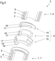
Figure 6 is a schematic view of an transposed electrical conductor with electrical conductors and the junction according to an exemplary embodiment, and -
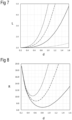
Figures 7 and 8 are exemplary diagrams. - The transposed
electrical conductor 2 according to the exemplary embodiment ofFigure 1 comprises two electrical conductors 1, in particular a first electrical conductor 6 and a second electrical conductor 7. Each of the electrical conductors 1 have a firstpartial conductor 3 and a secondpartial conductor 4. - The first
partial conductor 3 is a solid cylinder and the secondpartial conductor 4 is a hollow cylinder. The firstpartial conductor 3 is arranged within the hollow cylinder of the secondpartial conductor 4. - The solid cylinder as well as the hollow cylinder both extend along a
common cylinder axis 5. Anouter side surface 12 of the solid cylinder being the firstpartial conductor 3 faces aninner side surface 11 of the hollow cylinder being the secondpartial conductor 4. Theouter side surface 12 of the firstpartial conductor 3 and theinner side surface 11 of the secondpartial conductor 4 are separated in space via afirst gap 20. Thefirst gap 20 is further configured to electrically insulate the firstpartial conductor 3 from the secondpartial conductor 4. - The first
partial conductor 3 of the first electrical conductor 6 is electrically connected to the secondpartial conductor 4 of the second electrical conductor 7 via ajunction 8, in particular afirst part 13 of thejunction 8. Further, the secondpartial conductor 4 of the first electrical conductor 6 is electrically connected to the firstpartial conductor 3 of the second electrical conductor 7 via thejunction 8, in particular asecond part 14 of thejunction 8. - A transposing portion of each part of the junction, i.e. a portion through which the current flows in the substantially radial direction from the radial position of one partial conductor to the radial position of the other one, has a length LTP along the
common cylinder axis 5. The length of the transposing portion LTP along thecommon cylinder axis 5, which is a main extension direction of the electrical conductors 1, is at most 300 % and/or at least 30 % of a skin depth at an operating frequency of the transposedelectrical conductor 2. - Furthermore, a thickness in radial direction of the
common cylinder axis 5 of the secondpartial conductor 4 is at most 90 % of the skin depth at the operating frequency of the transposedelectrical conductor 2. The thickness of the second partial conductor d2 is at least 50 % of the skin depth at the operating frequency of the transposedelectrical conductor 2. - Such a maximal and minimal thickness for electrical conductors 1 in a transposed
electrical conductor 2 provide AC losses, which are advantageously surprisingly low in combination with saving material costs. - The transposed
electrical conductor 2 according to the exemplary embodiment ofFigure 2 is a cross sectional view in radial direction, which is rotated by 90° with respect to the transposedelectrical conductor 2 according to the exemplary embodiment ofFigure 3 . - The transposed
electrical conductor 2 according to the exemplary embodiment ofFigure 4 comprises in comparison to one of the electrical conductors 1 ofFigures 1, 2 or 3 electrical conductors 1 with a firstpartial conductor 3, a secondpartial conductor 4 and a thirdpartial conductor 9. - Each of the partial conductors are formed of a hollow cylinder. The first
partial conductor 3 is arranged within the secondpartial conductor 4. Further, the firstpartial conductor 3 and the secondpartial conductor 4 are arranged within the thirdpartial conductor 9. This is that the firstpartial conductor 3 has a diameter which is smaller than a diameter of the secondpartial conductor 4 and the diameter of the secondpartial conductor 4 is smaller than a diameter of the thirdpartial conductor 9. - Furthermore, a thickness in radial direction of the
common cylinder axis 5 of the secondpartial conductor 4 is at most 90 % of the skin depth at the operating frequency of the transposed electrical conductor 2and a thickness in radial direction of thecommon cylinder axis 5 of the thirdpartial conductor 9 is at most 75 % of the skin depth at the operating frequency of the transposedelectrical conductor 2. The thickness of the second partial conductor d2 is at least 50 % of the skin depth at the operating frequency of transposed electrical conductor 2and the thickness of the third partial conductor d3 is at least 40 % of the skin depth at the operating frequency of the transposedelectrical conductor 2. - The length of the transposing portion LTP corresponds to the lengths described in connection with
Figure 1 . - In particular, the first
partial conductor 3 of the first electrical conductor 6 is electrically connected to the secondpartial conductor 4 of the second electrical conductor 7. Further, the secondpartial conductor 4 of the first electrical conductor 6 is electrically connected to the thirdpartial conductor 9 of the second electrical conductor 7. The thirdpartial conductor 9 of the first electrical conductor 6 is electrically connected to the firstpartial conductor 3 of the second electrical conductor 7. - The transposed
electrical conductor 2 according to the exemplary embodiment ofFigure 5 comprises in comparison to the exemplary embodiment ofFigure 4 a firstpartial conductor 3, which is a solid cylinder, as described in connection withFigure 1 . - The transposed
electrical conductor 2 according to the exemplary embodiment ofFigure 6 comprises, as shown inFigure 4 , a first electrical conductor 6 and a second electrical conductor 7 each having a firstpartial conductor 3, a secondpartial conductor 4 and a thirdpartial conductor 9, each being a hollow cylinder. - The third
partial conductor 9 of the second electrical conductor 7 protrudes in direction of thecommon cylinder axis 5 beyond the firstpartial conductor 3 and the secondpartial conductor 4, on a side of the second electrical conductor 7 facing the first electrical conductor 6. This is to say that the thirdpartial conductor 9 of the second electrical conductor 7 has a length along thecommon cylinder axis 5, which is larger than a length of the firstpartial conductor 3 and the secondpartial conductor 4. Thus, an annulus base of the thirdpartial conductor 9 is closer to the neighbouring electrical conductor than the annulus bases of the firstpartial conductor 3 and/or the secondpartial conductor 4. - It is conceivable that the second
partial conductor 4 of the second electrical conductor 7 protrudes in direction of thecommon cylinder axis 5 beyond the firstpartial conductor 3, at the side facing the first electrical conductor 6. This is to say that the secondpartial conductor 4 of the second electrical conductor 7 has a length along thecommon cylinder axis 5, which is larger than a length of the firstpartial conductor 3. Thus, an annulus base of the secondpartial conductor 4 is closer to the neighbouring electrical conductor than the annulus base of the firstpartial conductor 3. The annulus base of the secondpartial conductor 4 is arranged between annulus base of the firstpartial conductor 3 and the annulus base of the thirdpartial conductor 9 along thecommon cylinder axis 5. - The
junction 8 has afirst part 13 electrically connecting the firstpartial conductor 3 of the first electrical conductor 6 with the secondpartial conductor 4 of the second electrical conductor 7. Thefirst part 13 has afirst sub-part 17 and asecond sub-part 18. Thefirst sub-part 17 is in direct and immediate contact to the annulus base of the firstpartial conductor 3 of the first electrical conductor 6. Further, thesecond sub-part 18 is in direct and immediate contact to the annulus base of the secondpartial conductor 4 of the second electrical conductor 7. The first sub-part and the second sub-part are formed in one piece. Further, thefirst sub-part 17 is exemplarily brazed to the firstpartial conductor 3 of the first electrical conductor 6 and thesecond sub-part 18 is exemplarily brazed to the secondpartial conductor 4 of the second electrical conductor 7. - The
junction 8 further has asecond part 14 electrically connecting the secondpartial conductor 4 of the first electrical conductor 6 with the thirdpartial conductor 9 of the second electrical conductor 7. Thesecond part 14 has afirst sub-part 17 and asecond sub-part 18. Thefirst sub-part 17 is in direct and immediate contact to the annulus base of the secondpartial conductor 4 of the first electrical conductor 6. Further, thesecond sub-part 18 is in direct and immediate contact to the annulus base of the thirdpartial conductor 9 of the second electrical conductor 7. The first sub-part and the second sub-part are formed in one piece. Further, thefirst sub-part 17 is exemplarily brazed to the secondpartial conductor 4 of the first electrical conductor 6 and thesecond sub-part 18 is exemplarily brazed to the thirdpartial conductor 9 of the second electrical conductor 7. - The
junction 8 additionally has athird part 15 electrically connecting the thirdpartial conductor 9 of the first electrical conductor 6 with the firstpartial conductor 3 of the second electrical conductor 7. Thethird part 15 has afirst sub-part 17, asecond sub-part 18 and athird sub-part 19. Thefirst sub-part 17 is in direct and immediate contact to the annulus base of the thirdpartial conductor 9 of the first electrical conductor 6. Further, thesecond sub-part 18 is in direct and immediate contact to the annulus base of the firstpartial conductor 3 of the second electrical conductor 7. The third sub-part 19 electrically connects the first sub-part 17 with thesecond sub-part 18. - The first sub-part and the third sub-part as well as the third sub-part and the second sub-part are formed in one piece. Further, the
first sub-part 17 is exemplarily brazed to the thirdpartial conductor 9 of the first electrical conductor 6 and thesecond sub-part 18 is exemplarily brazed to the firstpartial conductor 3 of the second electrical conductor 7. - For example, the sub-parts being in direct and immediate contact to the annulus bases, cover the respective annulus bases by at least 30 % or at least 40 %. Due to such a comparatively large interface of annulus base and sub-parts, the transmission of power is advantageously effective.
- The exemplary diagram of
Figure 7 shows an AC-resistance factor L on the y-axis, being representative for losses of and AC current flowing within a partial conductor divided by losses of a DC current of the magnitude equal to the effective magnitude of the AC current when flowing within that partial conductor, dependent on the thickness d of the partial conductor, as shown on the x-axis. The thickness d is indicated in the units of the skin depth. The solid line is characteristic for a secondpartial conductor 4, the dashed line with wide gaps is characteristic for a thirdpartial conductor 9 and the dashed line with small gaps is characteristic for a fourth partial conductor 10. The dotted line is characteristic for a firstpartial conductor 3, which is a hollow cylinder. - The exemplary diagram of
Figure 8 shows an AC-resistance R per unit length in µΩ/m on the y-axis dependent on the thickness d of the partial conductor, as shown on the x-axis. The thickness d is indicated in the units of the skin depth. The solid line is characteristic for a secondpartial conductor 4, the dashed line with wide gaps is characteristic for a thirdpartial conductor 9 and the dashed line with small gaps is characteristic for a fourth partial conductor 10. -
- 1
- Electrical conductor
- 2
- Transposed electrical conductor
- 3
- first partial conductor
- 4
- second partial conductor
- 5
- common cylinder axis
- 6
- first electrical conductor
- 7
- second electrical conductor
- 8
- junction
- 9
- third partial conductor
- 10
- fourth partial conductor
- 11
- inner side surface
- 12
- outer side surface
- 13
- first part
- 14
- second part
- 15
- third part
- 16
- fourth part
- 17
- first sub-part
- 18
- second sub-part
- 19
- third sub-part
- 20
- gap
- d2
- thickness of the second partial conductor
- d3
- thickness of the third partial conductor
- d4
- thickness of the fourth partial conductor
- LTP
- length of the transposing portion
- d
- thickness
- L
- AC resistance factor
- R
- AC resistance
Claims (14)
- Transposed electrical conductor (2) for electric power transmission at voltages of at least 1 kV, with- at least two electrical conductors (1) comprising a first electrical conductor (6) and a second electrical conductor (7), wherein- each of the at least two electrical conductors (1) comprises at least two partial conductors,- the at least two partial conductors comprise a first partial conductor (3) and a second partial conductor (4),- the second partial conductor (4) is a hollow cylinder,- the first partial conductor (3) is arranged within the hollow cylinder,- the first electrical conductor (6) and the second electrical conductor (7) are electrically connected by a junction (8), and- a thickness of the second partial conductor (d2) is at most 90 % of a skin depth at an operating frequency of the transposed electrical conductor (2).
- Transposed electrical conductor (2) according to claim 1, wherein- the first partial conductor (3) is a solid cylinder, or- the first partial conductor (3) is a hollow cylinder.
- Transposed electrical conductor (2) according to one of claims 1 or 2, wherein the first electrical conductor (6) and the second electrical conductor (7) have approximately the same length.
- Transposed electrical conductor (2) according to one of claims 1 to 3, wherein the thickness of the second partial conductor (d2) is at most 80 % of the skin depth at the operating frequency of the transposed electrical conductor (2) .
- Transposed electrical conductor (2) according to one of claims 1 to 4, wherein the thickness of the second partial conductor (d2) is at least 50 % of the skin depth at the operating frequency of the transposed electrical conductor (2) .
- Transposed electrical conductor (2) according to one of claims 1 to 5, wherein- each of the at least two electrical conductors (1) comprises at least three partial conductors, wherein- the at least three partial conductors comprise additionally a third partial conductor (9),- the third partial conductor (9) is a hollow cylinder,- the second partial conductor (4) is arranged within the hollow cylinder of the third partial conductor (9), and- a thickness of the third partial conductor (d3) is at most 75 % or at most 65 % and/or at least 40 % of a skin depth at an operating frequency of the transposed electrical conductor (2) .
- Transposed electrical conductor (2) according to claim 6, wherein- each of the at least two electrical conductors (1) comprises at least four partial conductors, wherein- the at least four partial conductors comprise additionally a fourth partial conductor (10),- the fourth partial conductor (10) is a hollow cylinder,- the third partial conductor (9) is arranged within the hollow cylinder of the fourth partial conductor (10), and- a thickness of the fourth partial conductor (d4) is at most 65 % or at most 55 % and/or at least 30 % of a skin depth at an operating frequency of the transposed electrical conductor (2) .
- Transposed electrical conductor (2) according to one of claims 1 to 7, wherein- the junction (8) electrically connects the first partial conductor (3) of the first electrical conductor (6) to the second partial conductor (4) of the second electrical conductor (7), and- the junction (8) electrically connects the second partial conductor (4) of the first electrical conductor (6) to the first partial conductor (3) of the second electrical conductor (7).
- Transposed electrical conductor (2) according to one of claims 1 to 7, wherein- the junction (8) electrically connects the first partial conductor (3) of the first electrical conductor (6) to the second partial conductor (4) of the second electrical conductor (7),- the junction (8) electrically connects the second partial conductor (4) of the first electrical conductor (6) to the third partial conductor (9) of the second electrical conductor (7), and- the junction (8) electrically connects the third partial conductor (9) of the first electrical conductor (6) to the first partial conductor (3) of the second electrical conductor (7).
- Transposed electrical conductor (2) according to one of claims 1 to 7, wherein- the junction (8) electrically connects the first partial conductor (3) of the first electrical conductor (6) to the second partial conductor (4) of the second electrical conductor (7),- the junction (8) electrically connects the second partial conductor (4) of the first electrical conductor (6) to the third partial conductor (9) of the second electrical conductor (7),- the junction (8) electrically connects the third partial conductor (9) of the first electrical conductor (6) to the fourth partial conductor (10) of the second electrical conductor (7), and- the junction (8) electrically connects the fourth partial conductor (10) of the first electrical conductor (6) to the first partial conductor (3) of the second electrical conductor (7).
- Transposed electrical conductor (2) according to one of claims 1 to 10, wherein the junction (8) comprises at least two parts being electrically insulated from one another.
- Transposed electrical conductor (2) according claim 11, wherein at least one part of the at least two parts comprises at least two sub-parts being formed in one piece.
- Transposed electrical conductor (2) according to one of claims 1 to 12, wherein a transposing portion of each part has a length (LTP) along the main extension direction of at most 300 % and/or at least 30 % of the skin depth at an operating frequency of the transposed electrical conductor (2) .
- Bushing comprising the transposed electrical conductor (2) comprising electrical conductors (1) according to one of claims 1 to 12.
Priority Applications (3)
| Application Number | Priority Date | Filing Date | Title |
|---|---|---|---|
| EP22217101.9A EP4394805A1 (en) | 2022-12-29 | 2022-12-29 | Transposed electrical conductor and bushing |
| PCT/EP2023/076056 WO2024141187A1 (en) | 2022-12-29 | 2023-09-21 | Transposed electrical conductor and bushing |
| CN202380089241.5A CN120500730A (en) | 2022-12-29 | 2023-09-21 | Transposed conductors and bushings |
Applications Claiming Priority (1)
| Application Number | Priority Date | Filing Date | Title |
|---|---|---|---|
| EP22217101.9A EP4394805A1 (en) | 2022-12-29 | 2022-12-29 | Transposed electrical conductor and bushing |
Publications (1)
| Publication Number | Publication Date |
|---|---|
| EP4394805A1 true EP4394805A1 (en) | 2024-07-03 |
Family
ID=84689037
Family Applications (1)
| Application Number | Title | Priority Date | Filing Date |
|---|---|---|---|
| EP22217101.9A Pending EP4394805A1 (en) | 2022-12-29 | 2022-12-29 | Transposed electrical conductor and bushing |
Country Status (3)
| Country | Link |
|---|---|
| EP (1) | EP4394805A1 (en) |
| CN (1) | CN120500730A (en) |
| WO (1) | WO2024141187A1 (en) |
Citations (3)
| Publication number | Priority date | Publication date | Assignee | Title |
|---|---|---|---|---|
| GB821009A (en) * | 1956-11-26 | 1959-09-30 | Western Electric Co | Improvements in or relating to electrical transmission lines |
| EP0022269A1 (en) * | 1979-07-10 | 1981-01-14 | Paul Prof. Dr.-Ing. Weiss | Current conductor with transposed partial conductors |
| EP4044200A1 (en) * | 2021-02-16 | 2022-08-17 | Hitachi Energy Switzerland AG | Conductor for electric current, method of manufacturing the conductor and use of conductor for conducting electric current with ac component |
-
2022
- 2022-12-29 EP EP22217101.9A patent/EP4394805A1/en active Pending
-
2023
- 2023-09-21 CN CN202380089241.5A patent/CN120500730A/en active Pending
- 2023-09-21 WO PCT/EP2023/076056 patent/WO2024141187A1/en not_active Ceased
Patent Citations (3)
| Publication number | Priority date | Publication date | Assignee | Title |
|---|---|---|---|---|
| GB821009A (en) * | 1956-11-26 | 1959-09-30 | Western Electric Co | Improvements in or relating to electrical transmission lines |
| EP0022269A1 (en) * | 1979-07-10 | 1981-01-14 | Paul Prof. Dr.-Ing. Weiss | Current conductor with transposed partial conductors |
| EP4044200A1 (en) * | 2021-02-16 | 2022-08-17 | Hitachi Energy Switzerland AG | Conductor for electric current, method of manufacturing the conductor and use of conductor for conducting electric current with ac component |
Also Published As
| Publication number | Publication date |
|---|---|
| WO2024141187A1 (en) | 2024-07-04 |
| CN120500730A (en) | 2025-08-15 |
Similar Documents
| Publication | Publication Date | Title |
|---|---|---|
| EP0888628B1 (en) | Transformer/reactor | |
| EP2214191B1 (en) | Gas-insulated equipment | |
| US7474030B2 (en) | Magnetic coils for electrical machines | |
| CA2390335C (en) | Electrical machine with a winding | |
| US2788456A (en) | Conductor-ventilated generators | |
| CN107851987B (en) | Apparatus for establishing multiphase electrical connections and equipment with corresponding apparatus | |
| US12494303B2 (en) | Conductor for electric current, method of manufacturing the conductor and use of conductor for conducting electric current with AC component | |
| KR102840873B1 (en) | Sinusoidal tubular conductive busbar | |
| WO2024141187A1 (en) | Transposed electrical conductor and bushing | |
| US1292659A (en) | Conductor. | |
| EP3973604B1 (en) | Shielded busbar | |
| KR100742499B1 (en) | Magnetically shielded superconducting cable core and superconducting cable having the same | |
| RU2444076C1 (en) | Transformer | |
| US20060044100A1 (en) | Windings for electrical machines | |
| JP4805688B2 (en) | Superconducting wire and superconducting device using the same | |
| US12294261B2 (en) | Strip conductor device and cable which contains the strip conductor device | |
| CN113056862B (en) | Multi-layer neutral bus | |
| US4712033A (en) | Acyclic generator with liquid metal current collectors having circulating current barriers | |
| EP2117014B1 (en) | High voltage bushing contact, high voltage bushing comprising such contact and high voltage device comprising bushing with such contact | |
| JP2000260636A (en) | Stationary guidance equipment | |
| KR20260053750A (en) | Busbar for transformer | |
| Edwards | Field distortion parameters for a nonaxisymmetric cylindrical transmission line | |
| JPS58218845A (en) | Armature coil for rotary electric machine | |
| KR860001587Y1 (en) | Carbon brush | |
| JP2022080949A (en) | Switch gear |
Legal Events
| Date | Code | Title | Description |
|---|---|---|---|
| PUAI | Public reference made under article 153(3) epc to a published international application that has entered the european phase |
Free format text: ORIGINAL CODE: 0009012 |
|
| STAA | Information on the status of an ep patent application or granted ep patent |
Free format text: STATUS: THE APPLICATION HAS BEEN PUBLISHED |
|
| AK | Designated contracting states |
Kind code of ref document: A1 Designated state(s): AL AT BE BG CH CY CZ DE DK EE ES FI FR GB GR HR HU IE IS IT LI LT LU LV MC ME MK MT NL NO PL PT RO RS SE SI SK SM TR |
|
| STAA | Information on the status of an ep patent application or granted ep patent |
Free format text: STATUS: REQUEST FOR EXAMINATION WAS MADE |
|
| 17P | Request for examination filed |
Effective date: 20241111 |
|
| RBV | Designated contracting states (corrected) |
Designated state(s): AL AT BE BG CH CY CZ DE DK EE ES FI FR GB GR HR HU IE IS IT LI LT LU LV MC ME MK MT NL NO PL PT RO RS SE SI SK SM TR |