EP4394744A1 - Human body simulation device - Google Patents
Human body simulation device Download PDFInfo
- Publication number
- EP4394744A1 EP4394744A1 EP22861026.7A EP22861026A EP4394744A1 EP 4394744 A1 EP4394744 A1 EP 4394744A1 EP 22861026 A EP22861026 A EP 22861026A EP 4394744 A1 EP4394744 A1 EP 4394744A1
- Authority
- EP
- European Patent Office
- Prior art keywords
- gas
- liquid
- separation tank
- liquid separation
- model
- Prior art date
- Legal status (The legal status is an assumption and is not a legal conclusion. Google has not performed a legal analysis and makes no representation as to the accuracy of the status listed.)
- Pending
Links
Images





Classifications
-
- G—PHYSICS
- G09—EDUCATION; CRYPTOGRAPHY; DISPLAY; ADVERTISING; SEALS
- G09B—EDUCATIONAL OR DEMONSTRATION APPLIANCES; APPLIANCES FOR TEACHING, OR COMMUNICATING WITH, THE BLIND, DEAF OR MUTE; MODELS; PLANETARIA; GLOBES; MAPS; DIAGRAMS
- G09B23/00—Models for scientific, medical, or mathematical purposes, e.g. full-sized devices for demonstration purposes
- G09B23/28—Models for scientific, medical, or mathematical purposes, e.g. full-sized devices for demonstration purposes for medicine
- G09B23/30—Anatomical models
- G09B23/32—Anatomical models with moving parts
-
- G—PHYSICS
- G09—EDUCATION; CRYPTOGRAPHY; DISPLAY; ADVERTISING; SEALS
- G09B—EDUCATIONAL OR DEMONSTRATION APPLIANCES; APPLIANCES FOR TEACHING, OR COMMUNICATING WITH, THE BLIND, DEAF OR MUTE; MODELS; PLANETARIA; GLOBES; MAPS; DIAGRAMS
- G09B23/00—Models for scientific, medical, or mathematical purposes, e.g. full-sized devices for demonstration purposes
- G09B23/28—Models for scientific, medical, or mathematical purposes, e.g. full-sized devices for demonstration purposes for medicine
-
- G—PHYSICS
- G09—EDUCATION; CRYPTOGRAPHY; DISPLAY; ADVERTISING; SEALS
- G09B—EDUCATIONAL OR DEMONSTRATION APPLIANCES; APPLIANCES FOR TEACHING, OR COMMUNICATING WITH, THE BLIND, DEAF OR MUTE; MODELS; PLANETARIA; GLOBES; MAPS; DIAGRAMS
- G09B23/00—Models for scientific, medical, or mathematical purposes, e.g. full-sized devices for demonstration purposes
- G09B23/28—Models for scientific, medical, or mathematical purposes, e.g. full-sized devices for demonstration purposes for medicine
- G09B23/288—Models for scientific, medical, or mathematical purposes, e.g. full-sized devices for demonstration purposes for medicine for artificial respiration or heart massage
-
- G—PHYSICS
- G09—EDUCATION; CRYPTOGRAPHY; DISPLAY; ADVERTISING; SEALS
- G09B—EDUCATIONAL OR DEMONSTRATION APPLIANCES; APPLIANCES FOR TEACHING, OR COMMUNICATING WITH, THE BLIND, DEAF OR MUTE; MODELS; PLANETARIA; GLOBES; MAPS; DIAGRAMS
- G09B23/00—Models for scientific, medical, or mathematical purposes, e.g. full-sized devices for demonstration purposes
- G09B23/28—Models for scientific, medical, or mathematical purposes, e.g. full-sized devices for demonstration purposes for medicine
- G09B23/30—Anatomical models
-
- G—PHYSICS
- G09—EDUCATION; CRYPTOGRAPHY; DISPLAY; ADVERTISING; SEALS
- G09B—EDUCATIONAL OR DEMONSTRATION APPLIANCES; APPLIANCES FOR TEACHING, OR COMMUNICATING WITH, THE BLIND, DEAF OR MUTE; MODELS; PLANETARIA; GLOBES; MAPS; DIAGRAMS
- G09B23/00—Models for scientific, medical, or mathematical purposes, e.g. full-sized devices for demonstration purposes
- G09B23/28—Models for scientific, medical, or mathematical purposes, e.g. full-sized devices for demonstration purposes for medicine
- G09B23/30—Anatomical models
- G09B23/303—Anatomical models specially adapted to simulate circulation of bodily fluids
Definitions
- Patent Literature 1 discloses a heart simulator that allows an operator, such as a doctor, to simulate a procedure using such a medical device.
- the heart simulator described in Patent Literature 1 includes a heart model having a plurality of mutually independent ventricles and a fluid supply/discharge device that supplies and discharges a fluid to and from the heart model, and causes the heart model to beat by supplying and discharging the fluid to and from each of the ventricles of the heart model.
- Patent Literature 2 discloses a liquid container capable of suppressing mixing of gas into a liquid to be accommodated.
- the present invention has been made to solve the above-described problems, and an object thereof is to make an X-ray image of an organ model closer to an actual clinical image, and to improve the operability of a human body simulation device.
- the organ model is expanded by supplying the liquid from the gas-liquid separation tank to the liquid accommodating part, and the organ model is contracted by sucking the liquid from the liquid accommodating part to the gas-liquid separation tank.
- the liquid accommodating part of the organ model is filled with liquid such as water or physiological saline due to expansion and contraction of the organ model, it is possible to suppress white appearance on the X-ray image and to make the X-ray image of the organ model closer to an actual clinical image, compared to a case where the liquid accommodating part is filled with gas such as air.
- the gas-liquid separation tank may include a partition member that partitions the internal space of the gas-liquid separation tank into a first space for accommodating a gas and a second space for accommodating a liquid, the second space being located below the first space in a vertical direction, and may have a first opening that connects the first space with an outside and a second opening that connects the second space with the outside, and may be connected to the gas supply/suction device via the first opening and connected to the liquid accommodating part of the organ model via the second opening.
- the gas-liquid separation tank includes the partition member that partitions the internal space of the gas-liquid separation tank into the first space for accommodating the gas and the second space for accommodating the liquid, and the gas-liquid separation tank is connected to the gas supply/suction device via the first opening that connects the first space with the outside and is connected to the liquid accommodating part of the organ model via the second opening that connects the second space with the outside. Therefore, when the gas is supplied from the gas supply/suction device into the first space, and therefore, it is possible to suppress an occurrence of cavitation in the liquid in the second space due to the presence of the partition member between the first and second spaces.
- the gas in the first space is sucked by the gas supply/suction device, it is possible to suppress entry of the liquid into the first space due to the presence of the partition member between the first and second spaces. As a result, the operability of the human body simulation device can be further improved.
- the partition member may have a flat plate shape having a first main surface facing the first space and a second main surface facing the second space, and the partition member may further include a through-hole penetrating the first main surface and the second main surface formed therein.
- the control device since the control device repeats the motion of causing the gas supply/suction device to supply the first predetermined amount of gas to the gas-liquid separation tank for the first predetermined time and then causing the gas supply/suction device to suck the second predetermined amount of gas from the gas-liquid separation tank for the second predetermined time, it is possible to regularly expand and contract the organ model.
- the control device when the gas supply/suction device supplies the gas to the gas-liquid separation tank for the first time after the control device is started, the control device causes the first predetermined amount of gas to be supplied to the gas-liquid separation tank for the third predetermined time that is longer than the first predetermined time. Therefore, it is possible to suppress damage to the organ model due to rapid expansion.
- a human body simulation device having a beating heart model can be provided.
- the organ model may be a diaphragm model simulating an outer shape of a diaphragm
- the gas supply/suction device and the gas-liquid separation tank may function as a respiratory motion portion that simulates a movement of the diaphragm model associated with a respiratory motion by expanding and contracting the diaphragm model.
- a portion through which a liquid 22 (simulated blood) flows is indicated by dot hatching, and a portion through which a liquid for expansion/contraction of the heart model 110 and the diaphragm model 170 flows is indicated by oblique hatching.
- Fig. 9 is an explanatory diagram illustrating a configuration of a gas-liquid separation tank 420A according to a second embodiment.
- a human body simulation device 1 according to the second embodiment includes the gas-liquid separation tank 420A to be illustrated in Fig. 9 , instead of the gas-liquid separation tank 420 described with reference to Fig. 4 .
- the gas-liquid separation tank 420A does not include the partition member 4211 in the configuration described in Fig. 4 , and has a single internal space R. As described with reference to Fig.
- the configuration of the gas-liquid separation tank 420A can be variously changed, and the gas-liquid separation tank 420A may be configured to have a single internal space R.
- Such a human body simulation device 1 having the gas-liquid separation tank 420A according to the second embodiment can also exhibit similar effects to those of the first embodiment described above.
Landscapes
- Engineering & Computer Science (AREA)
- Physics & Mathematics (AREA)
- General Physics & Mathematics (AREA)
- Health & Medical Sciences (AREA)
- Mathematical Analysis (AREA)
- Pure & Applied Mathematics (AREA)
- Medical Informatics (AREA)
- Algebra (AREA)
- Computational Mathematics (AREA)
- General Health & Medical Sciences (AREA)
- Chemical & Material Sciences (AREA)
- Mathematical Optimization (AREA)
- Mathematical Physics (AREA)
- Medicinal Chemistry (AREA)
- Business, Economics & Management (AREA)
- Educational Administration (AREA)
- Educational Technology (AREA)
- Theoretical Computer Science (AREA)
- Cardiology (AREA)
- Heart & Thoracic Surgery (AREA)
- Instructional Devices (AREA)
Abstract
Description
- The present invention relates to a human body simulation device.
- A medical device such as a catheter is used for minimally invasive treatment or examination inside a living body lumen such as a circulatory system or a digestive system. For example, Patent Literature 1 discloses a heart simulator that allows an operator, such as a doctor, to simulate a procedure using such a medical device. The heart simulator described in Patent Literature 1 includes a heart model having a plurality of mutually independent ventricles and a fluid supply/discharge device that supplies and discharges a fluid to and from the heart model, and causes the heart model to beat by supplying and discharging the fluid to and from each of the ventricles of the heart model. In addition, Patent Literature 2 discloses a liquid container capable of suppressing mixing of gas into a liquid to be accommodated.
-
- Patent Literature 1:
JP 2006-276258 A - Patent Literature 2:
JP 2019-1542 A - Herein, in order to perform a procedure while checking a behavior of a heart model or a medical device in the heart model, an operator such as a doctor acquires an X-ray image of the heart model and performs the procedure while checking the X-ray image. However, in the heart simulator described in Patent Literature 1, when a gas such as air is used as the fluid, there is a problem that air filled in the heart model appears white on the X-ray image and an X-ray image very different from an actual clinical image is acquired. In addition, in the heart simulator described in Patent Literature 1, when a liquid such as water is used as the fluid, an X-ray image close to an actual clinical image is acquired, but it is not easy to control the liquid in the fluid supply/discharge device without water leakage, and there is a problem in that operability is poor.
- Further, in the technique described in Patent Literature 2, no consideration is given on using a liquid for beating of the heart model. Such a problem is not limited to a case of reproducing the beating of the heart model, but is a problem common to organ models of the human body, such as a case of simulating a movement of a diaphragm model associated with a respiratory motion, a case of simulating a movement of a lung model associated with the respiratory motion, and the like.
- The present invention has been made to solve the above-described problems, and an object thereof is to make an X-ray image of an organ model closer to an actual clinical image, and to improve the operability of a human body simulation device.
- The present invention has been made to solve at least a part of the above-described problems, and can be implemented as the following aspects.
-
- (1) According to one aspect of the present invention, a human body simulation device is provided. The human body simulation device includes an organ model simulating an outer shape of an organ and having a liquid accommodating part, which is a space capable of accommodating a liquid therein, a gas-liquid separation tank having an internal space for accommodating a gas and a liquid in a separated state, and a gas supply/suction device that supplies a gas to the internal space of the gas-liquid separation tank or sucking the gas accommodated in the internal space of the gas-liquid separation tank. The internal space of the gas-liquid separation tank and the liquid accommodating part of the organ model are connected to each other by a communication member through which the liquid accommodated in the gas-liquid separation tank flows, and when a gas is supplied from the gas supply/suction device to the gas-liquid separation tank, a liquid in an amount corresponding to an amount of the supplied gas is supplied from the gas-liquid separation tank to the liquid accommodating part, whereby the organ model expands, and when a gas is sucked from the gas-liquid separation tank by the gas supply/suction device, a liquid in an amount corresponding to an amount of the sucked gas is sucked from the liquid accommodating part to the gas-liquid separation tank, whereby the organ model contracts.
- According to this configuration, the organ model is expanded by supplying the liquid from the gas-liquid separation tank to the liquid accommodating part, and the organ model is contracted by sucking the liquid from the liquid accommodating part to the gas-liquid separation tank. Namely, since the liquid accommodating part of the organ model is filled with liquid such as water or physiological saline due to expansion and contraction of the organ model, it is possible to suppress white appearance on the X-ray image and to make the X-ray image of the organ model closer to an actual clinical image, compared to a case where the liquid accommodating part is filled with gas such as air. Further, when a gas is supplied from the gas supply/suction device to the gas-liquid separation tank, a liquid in an amount corresponding to an amount of the supplied gas is supplied from the gas-liquid separation tank to the liquid accommodating part, and when a gas is sucked from the gas-liquid separation tank by the gas supply/suction device, a liquid in an amount corresponding to an amount of the sucked gas is sucked from the liquid accommodating part to the gas-liquid separation tank. Namely, the supply and suction of the liquid by the gas-liquid separation tank are performed in response to the supply and suction of the gas by the gas supply/suction device. Therefore, in the gas supply/suction device, the gas can be controlled without water leakage, and the operability of the human body simulation device can be improved.
- (2) In the human body simulation device according to the above-described aspect, the gas-liquid separation tank may include a partition member that partitions the internal space of the gas-liquid separation tank into a first space for accommodating a gas and a second space for accommodating a liquid, the second space being located below the first space in a vertical direction, and may have a first opening that connects the first space with an outside and a second opening that connects the second space with the outside, and may be connected to the gas supply/suction device via the first opening and connected to the liquid accommodating part of the organ model via the second opening.
- According to this configuration, the gas-liquid separation tank includes the partition member that partitions the internal space of the gas-liquid separation tank into the first space for accommodating the gas and the second space for accommodating the liquid, and the gas-liquid separation tank is connected to the gas supply/suction device via the first opening that connects the first space with the outside and is connected to the liquid accommodating part of the organ model via the second opening that connects the second space with the outside. Therefore, when the gas is supplied from the gas supply/suction device into the first space, and therefore, it is possible to suppress an occurrence of cavitation in the liquid in the second space due to the presence of the partition member between the first and second spaces. Further, when the gas in the first space is sucked by the gas supply/suction device, it is possible to suppress entry of the liquid into the first space due to the presence of the partition member between the first and second spaces. As a result, the operability of the human body simulation device can be further improved.
- (3) In the human body simulation device according to the above-described aspect, the partition member may have a flat plate shape having a first main surface facing the first space and a second main surface facing the second space, and the partition member may further include a through-hole penetrating the first main surface and the second main surface formed therein.
- According to this configuration, since the partition member has a flat plate shape having the first main surface facing the first space and the second main surface facing the second space, it is possible to effectively suppress mixing of air bubbles into the liquid in the second space and entry of the liquid into the first space. In addition, the second space is positioned below the first space in the vertical direction, and a through-hole penetrating the first main surface and the second main surface is formed in the partition member. Therefore, the liquid supplied into the first space can be guided to the second space via the through-hole of the partition member.
- (4) The human body simulation device according to the above-described aspect may further include a control device that controls a supply amount and a supply time of the gas by the gas supply/suction device and a suction amount and a suction time of the gas by the gas supply/suction device, wherein the control device repeats a motion of causing the gas supply/suction device to supply a first predetermined amount of gas to the gas-liquid separation tank for a first predetermined time and then causing the gas supply/suction device to suck a second predetermined amount of gas from the gas-liquid separation tank for a second predetermined time, and when the gas supply/suction device supplies the gas to the gas-liquid separation tank for the first time after the control device is started, the supply of the first predetermined amount of gas to the gas-liquid separation tank may be performed for a third predetermined time that is longer than the first predetermined time.
- According to this configuration, since the control device repeats the motion of causing the gas supply/suction device to supply the first predetermined amount of gas to the gas-liquid separation tank for the first predetermined time and then causing the gas supply/suction device to suck the second predetermined amount of gas from the gas-liquid separation tank for the second predetermined time, it is possible to regularly expand and contract the organ model. In addition, when the gas supply/suction device supplies the gas to the gas-liquid separation tank for the first time after the control device is started, the control device causes the first predetermined amount of gas to be supplied to the gas-liquid separation tank for the third predetermined time that is longer than the first predetermined time. Therefore, it is possible to suppress damage to the organ model due to rapid expansion.
- (5) In the human body simulation device according to the above-described aspect, the organ model may be a heart model simulating an outer shape of a heart, and the gas supply/suction device and the gas-liquid separation tank may function as a heartbeat portion that simulates beating of the heart model by expanding and contracting the heart model.
- According to this configuration, a human body simulation device having a beating heart model can be provided.
- (6) In the human body simulation device according to the above-described aspect, the organ model may be a diaphragm model simulating an outer shape of a diaphragm, and the gas supply/suction device and the gas-liquid separation tank may function as a respiratory motion portion that simulates a movement of the diaphragm model associated with a respiratory motion by expanding and contracting the diaphragm model.
- According to this configuration, it is possible to provide a human body simulation device having a diaphragm model that moves in association with a respiratory motion.
- Note that the present invention can be achieved in various aspects, for example, a human body simulation device, a heart simulator including a heart model, a diaphragm simulator including a diaphragm model, a lung simulator including a lung model, and a method of controlling these devices.
-
-
Fig. 1 is an explanatory diagram illustrating a configuration of a human body simulation device. -
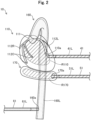
Fig. 2 is an explanatory diagram illustrating a configuration of a model. -
Fig. 3 is an explanatory diagram illustrating a configuration of a heartbeat portion. -
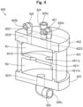
Fig. 4 is an explanatory diagram illustrating a sectional configuration of a gas-liquid separation tank. -
Fig. 5A and Fig. 5B are each a diagram for explaining a motion of expanding and contracting a heart model. -
Fig. 6A and Fig. 6B are each a diagram for explaining a motion of expanding and contracting the heart model. -
Fig. 7A and Fig. 7B are each a diagram for explaining a motion of expanding and contracting the heart model. -
Fig. 8A and Fig. 8B are each a diagram for explaining a motion of expanding and contracting the heart model. -
Fig. 9 is an explanatory diagram illustrating a configuration of a gas-liquid separation tank according to a second embodiment. -
Fig. 10 is an explanatory diagram illustrating a configuration of a gas-liquid separation tank according to a third embodiment. -
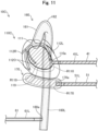
Fig. 11 is an explanatory diagram illustrating a configuration of a model according to a fourth embodiment. -
Fig. 12 is an explanatory diagram illustrating a configuration of a human body simulation device according to a fifth embodiment. -
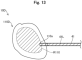
Fig. 13 is an explanatory diagram illustrating a configuration of a model according to the fifth embodiment. -
Fig. 1 is an explanatory diagram illustrating a configuration of a human body simulation device 1. The human body simulation device 1 according to the present embodiment is a device used for simulating a procedure of treatment or examination using medical devices for minimally invasive treatment or examination, such as a catheter and a guide wire, in a living body lumen such as a circulatory system, a digestive system, or a respiratory system of a human body. The human body simulation device 1 includes amodel 10, awater tank 21, afiltration filter 23, apump 24, acontrol device 30, aheartbeat portion 40, arespiratory motion portion 50, and apulsation portion 60. -
Fig. 2 is an explanatory diagram illustrating a configuration of themodel 10. As illustrated inFig. 2 , themodel 10 includes aheart model 110 simulating an outer shape of a heart of a human body, anaorta model 160 simulating an outer shape of an aorta of the human body, and adiaphragm model 170 simulating an outer shape of a diaphragm of the human body. Hereinafter, theheart model 110 and thediaphragm model 170 are also referred to as "organ models". Details of themodel 10 will be described later. InFig. 2 , a portion through which a liquid 22 (simulated blood) flows is indicated by dot hatching, and a portion through which a liquid for expansion/contraction of theheart model 110 and thediaphragm model 170 flows is indicated by oblique hatching. - The
water tank 21 is a substantially rectangular parallelepiped water tank whose upper part is opened. As illustrated inFig. 1 , themodel 10 is submerged in the liquid 22 by placing themodel 10 on a bottom surface of thewater tank 21 in a state where an inside of thewater tank 21 is filled with the liquid 22. As a result, themodel 10 can be maintained in a wet state similarly to the actual human body. Note that water, physiological saline, an aqueous solution of an arbitrary compound, or the like can be adopted as the liquid 22. The liquid 22 filled in thewater tank 21 is taken into theaorta model 160 and functions as simulated blood that simulates blood. Thewater tank 21 may be further provided with a wave-eliminating plate for covering a surface of the liquid 22. When the wave-eliminating plate is used, waving generated on the surface of the liquid 22 can be suppressed, and visibility of themodel 10 can be improved. Thewater tank 21 and the wave-eliminating plate can be formed of a synthetic resin (for example, acrylic resin) having X-ray permeability and high transparency, or an optional material. - The
control device 30 is configured by, for example, a personal computer, and includes a CPU, a ROM, a RAM, a storage portion, and an input/output interface, which are not illustrated. Thecontrol device 30 controls theheartbeat portion 40, therespiratory motion portion 50, thepulsation portion 60, and thepump 24 by loading a computer program stored in the ROM into the RAM and executing the computer program (Fig. 1 : broken line arrows). As the input/output interface of thecontrol device 30, an optional device, for example, a touch panel, a keyboard, an operation button, an operation dial, a foot switch, a microphone, a monitor, an indicator, a speaker, or the like can be used. - The
heartbeat portion 40 simulates the beating of theheart model 110 by expanding and contracting theheart model 110 of themodel 10. Specifically, theheartbeat portion 40 expands theheart model 110 by supplying a liquid into theheart model 110. Further, theheartbeat portion 40 contracts theheart model 110 by sucking the liquid inside theheart model 110. Details will be described later. Therespiratory motion portion 50 expands and contracts thediaphragm model 170 of themodel 10, and thereby simulates a movement of thediaphragm model 170 associated with the respiratory motion. Specifically, therespiratory motion portion 50 expands thediaphragm model 170 by supplying a liquid into thediaphragm model 170. In addition, therespiratory motion portion 50 contracts thediaphragm model 170 by sucking the liquid inside thediaphragm model 170. Details will be described later. - The
filtration filter 23 is connected to anopening 210 provided in thewater tank 21 via a tubular body. Thefiltration filter 23 removes impurities (for example, a contrast medium used in a procedure) in the liquid 22 by filtering the liquid 22 passing through thefiltration filter 23. Thepump 24 is connected downstream of thefiltration filter 23 and circulates the filteredliquid 22 at a constant flow rate. As thepump 24, for example, a non-positive displacement type centrifugal pump can be used. Thepulsation portion 60 has a built-in pulsation pump, and simulates blood flow from theaorta model 160 by delivering the liquid 22 to which pulsation is applied to aninner cavity 160L of the aorta model 160 (Fig. 2 ). As the pulsation pump, for example, a positive displacement reciprocating pump or a rotary pump operated at a low speed can be used. - As illustrated in
Fig. 2 , theheart model 110 of themodel 10 has an outer shape simulating an outer shape of the heart of the human body. A liquid accommodating part R110, which is a space capable of accommodating a liquid, is provided inside theheart model 110. The liquid accommodating part R110 communicates with an outside via anopening 110a provided at an arbitrary position in theheart model 110. The liquid accommodating part R110 is connected to the heartbeat portion 40 (to be specific, a gas-liquid separation tank 420 to be described inFig. 3 ) by afirst communication member 41 attached to a position where theopening 110a is provided in theheart model 110. Thefirst communication member 41 is a tubular member having afirst lumen 41L therein, and is used for allowing the liquid accommodated in the heartbeat portion 40 (to be specific, the gas-liquid separation tank 420) to flow. - A heart
blood vessel model 111 and a coronary artery model 112 are provided on an outer surface of theheart model 110. The heartblood vessel model 111 is a tubular blood vessel model simulating a part of the ascending aorta. A proximal end of the heartblood vessel model 111 is connected in a state in which the lumen thereof is made to communicate with theaorta model 160. The distal end of the heartblood vessel model 111 is connected in a state in which the lumen thereof is made to communicate with the coronary artery model 112. The coronary artery model 112 is a tubular blood vessel model simulating a coronary artery. As illustrated inFig. 2 , the coronary artery model 112 includes a tubular rightcoronary artery model 112R representing the right coronary artery and a tubular leftcoronary artery model 112L representing the left coronary artery. A distal end of each of the rightcoronary artery model 112R and the leftcoronary artery model 112L is provided with adistal end opening 1120 that allows the lumen of each of thecoronary artery models 112R and L to communicate with the outside. - The
aorta model 160 of themodel 10 has an outer shape simulating the outer shape of the aorta of the human body. Theinner cavity 160L through which a fluid is made to flow is provided inside theaorta model 160. Theinner cavity 160L communicates with the outside via anopening 160a provided at an optional position in theaorta model 160. Theinner cavity 160L of theaorta model 160 is connected to the pulsation portion 60 (Fig. 2 ) by athird communication member 61 attached to a position where theopening 160a is provided in theaorta model 160. Thethird communication member 61 is a tubular member having athird lumen 61L therein, and is used for allowing the liquid 22 delivered from thepulsation portion 60 to flow. To be specific, the liquid 22 (simulated blood) delivered from thepulsation portion 60 advances in theinner cavity 160L of theaorta model 160 toward theheart model 110 via thethird lumen 61L, passes through an inner cavity of a heartblood vessel model 111 and inner cavities ofcoronary artery models 112R and L, and is discharged from thedistal end opening 1120 into thewater tank 21. - The
diaphragm model 170 of themodel 10 has an outer shape simulating the outer shape of the diaphragm of the human body. Inside thediaphragm model 170, a liquid accommodating part R170, which is a space capable of accommodating liquid, is provided. The liquid accommodating part R170 communicates with the outside via anopening 170a provided at an arbitrary position in thediaphragm model 170. Thediaphragm model 170 is connected to therespiratory motion portion 50 by asecond communication member 51 attached to a position where theopening 170a is provided in thediaphragm model 170. Thesecond communication member 51 is a tubular member having asecond lumen 51L therein, and is used for allowing the liquid accommodated in therespiratory motion portion 50 to flow. - The
heart model 110, the heartblood vessel model 111, the coronary artery model 112, theaorta model 160, thediaphragm model 170, thefirst communication member 41, thesecond communication member 51, and thethird communication member 61 can be formed of a known material in addition to a soft synthetic resin (for example, silicon, etc.) having X-ray permeability. In addition, thefirst communication member 41, thesecond communication member 51, and thethird communication member 61 may be formed of a synthetic resin having X-ray permeability and a higher rigidity than silicon or the like. Theheart model 110, the heartblood vessel model 111, the coronary artery model 112, theaorta model 160, thediaphragm model 170, thefirst communication member 41, thesecond communication member 51, and thethird communication member 61 may be formed of the same material or may be formed of different materials. -
Fig. 3 is an explanatory diagram illustrating a configuration of theheartbeat portion 40. As illustrated inFig. 3 , theheartbeat portion 40 of the present embodiment is composed of a gas supply/suction device 410 and a gas-liquid separation tank 420. - The gas supply/
suction device 410 is a device that supplies gas to the gas-liquid separation tank 420 or sucks the gas inside the gas-liquid separation tank 420. The gas supply/suction device 410 includes anelectric actuator 411 and anair cylinder 412. Theelectric actuator 411 is a device that electrically drives a piston disposed in an internal space of theair cylinder 412. Theair cylinder 412 is made of metal, and a piston is disposed in an internal space thereof. When theelectric actuator 411 moves the piston in a D1 direction inFig. 3 , the gas compressed by the piston in a housing of theair cylinder 412 is delivered to the outside via acylinder opening 410a of theair cylinder 412. In addition, when theelectric actuator 411 moves the piston in a D2 direction inFig. 3 , a negative pressure is generated in the housing of theair cylinder 412, and external gas is sucked through thecylinder opening 410a of theair cylinder 412. A supply amount and a supply time of the gas by the gas supply/suction device 410, and a suction amount and a suction time of the gas by the gas supply/suction device are controlled by the control device 30 (Fig. 1 ). -
Fig. 4 is an explanatory diagram illustrating a sectional configuration of the gas-liquid separation tank 420. The gas-liquid separation tank 420 is a device having internal spaces R1 and R2 for accommodating gas and liquid in a separated state. As illustrated inFig. 4 , the gas-liquid separation tank 420 of the present embodiment includes amain body part 421, anupper housing 422, alower housing 423, afirst connection portion 424, asecond connection portion 426, athird connection portion 425, afourth connection portion 427, and apartition member 4211. - The
main body part 421 is a cylindrical container. Theupper housing 422 is a lid provided on an upper side of themain body part 421 in a vertical direction, and has a disk shape. In theupper housing 422, three through-holes Fig. 4 : broken lines), which connect an upper surface and a lower surface of theupper housing 422 in the vertical direction, are formed. Thelower housing 423 is a bottom plate provided on a lower side of themain body part 421 in the vertical direction, and has a disk shape. In thelower housing 423, a through-hole 4231 (Fig. 4 : broken line), which connects an upper surface and a lower surface of thelower housing 423 in the vertical direction, is formed. - The
first connection portion 424 is a straight joint, and is attached to theupper housing 422 at a position where the through-hole 4221 is provided. Hereinafter, among openings at both ends of thefirst connection portion 424, the opening exposed to the outside is also referred to as a "first opening 420a". Thefirst opening 420a is an opening through which an internal space (a first space R1) of the gas-liquid separation tank 420 communicates with the outside. Thesecond connection portion 426 is an L-shaped joint, and is attached to thelower housing 423 at a position where the through-hole 4231 is provided. Hereinafter, among openings at both ends of thesecond connection portion 426, the opening exposed to the outside is also referred to as a "second opening 420c". Thesecond opening 420c is an opening through which an internal space (a second space R2) of the gas-liquid separation tank 420 communicates with the outside. - The
third connection portion 425 is an L-shaped joint, and is attached to theupper housing 422 at a position where the through-hole 4222 is provided. Hereinafter, among openings at both ends of thethird connection portion 425, the opening exposed to the outside is also referred to as a "third opening 420b". Thethird opening 420b is an opening that allows the internal space (first space R1) of the gas-liquid separation tank 420 to communicate with the outside. Thefourth connection portion 427 is an L-shaped joint, and is attached to theupper housing 422 at a position where the through-hole 4223 is provided. Hereinafter, among openings at both ends of thefourth connection portion 427, the opening exposed to the outside is also referred to as a "fourth opening 420d". Thefourth opening 420d is an opening that allows the internal space (first space R1) of the gas-liquid separation tank 420 to communicate with the outside. - The
partition member 4211 is a member for partitioning the internal space of the gas-liquid separation tank 420 into a first space R1 and a second space R2, and has a circular flat plate shape along an internal wall of themain body part 421. Herein, the first space R1 means a space for accommodating gas in the internal space of the gas-liquid separation tank 420. The second space R2 means a space for accommodating liquid in the internal space of the gas-liquid separation tank 420. As illustrated, the second space R2 is provided below the first space R1 in the vertical direction (in other words, on a side where thelower housing 423, thesecond connection portion 426, and thesecond opening 420c are provided). Such a positional relationship between the first space R1 and the second space R2 results from a structure in which the gas-liquid separation tank 420 separates gas and liquid from each other by gravity. - Of a pair of
main surfaces partition member 4211, a surface facing the first space R1 is referred to as a firstmain surface 4211a, and a surface facing the second space R2 is referred to as a secondmain surface 4211b. As illustrated inFig. 4 , a through-hole 4212 penetrating the firstmain surface 4211a and the secondmain surface 4211b is formed in thepartition member 4211. In the example of the present embodiment, three circular through-holes 4212 are formed in thepartition member 4211, and the three through-holes 4212 are provided at positions equally spaced apart from the center of the partition member 4211 (note thatFig. 4 is a cross-sectional view, and therefore only two through-holes 4212 are illustrated). Note that the inner diameter, number, and shape of the through-holes 4212 are merely examples, and can be arbitrarily changed. - Note that at least some of the
main body part 421, theupper housing 422, thelower housing 423, thefirst connection portion 424, thesecond connection portion 426, thethird connection portion 425, thefourth connection portion 427, and thepartition member 4211, which are described above, may be integrally configured instead of being separate members. For example, themain body part 421 and thepartition member 4211 may be integrally configured. For example, theupper housing 422, thefirst connection portion 424, thethird connection portion 425, and thefourth connection portion 427 may be integrally configured. Further, at least some of thefirst connection portion 424, thesecond connection portion 426, and thethird connection portion 425 may be omitted. For example, when thefirst connection portion 424 is omitted, an opening of the through-hole 4221 of theupper housing 422, which is exposed to the outside, is equivalent to the "first opening 420a". Similarly, when thethird connection portion 425 is omitted, an opening of the through-hole 4222 of theupper housing 422, which is exposed to the outside, is equivalent to the "third opening 420b". When thesecond connection portion 426 is omitted, an opening of the through-hole 4231 of thelower housing 423, which is exposed to the outside, is equivalent to the "second opening 420c". - Returning to
Fig. 3 , description will be continued. The gas supply/suction device 410 is connected to the first space R1 of the gas-liquid separation tank 420 by thecommunication member 42. Thecommunication member 42 is a tubular member having a lumen therein, and is used for allowing gas between the gas supply/suction device 410 and the gas-liquid separation tank 420 to flow. One end of thecommunication member 42 is attached to the gas supply/suction device 410 via thecylinder opening 410a. Another end of thecommunication member 42 is attached to the gas-liquid separation tank 420 via afirst opening 420a (Fig. 4 : first connection portion 424). A lumen in thecommunication member 42 functions as a flow path through which gas flows between the gas supply/suction device 410 and the gas-liquid separation tank 420. - The second space R2 of the gas-
liquid separation tank 420 is connected to the liquid accommodating part R110 of theheart model 110 by thefirst communication member 41. As described above, thefirst communication member 41 is a tubular member having afirst lumen 41L therein, and is used for allowing liquid between the gas-liquid separation tank 420 and theheart model 110 to flow. One end of thefirst communication member 41 is attached to the gas-liquid separation tank 420 via thesecond opening 420c (Fig. 4 : second connection portion 426). Another end of thefirst communication member 41 is attached to theheart model 110 via theopening 110a. Namely, as indicated by a solid line arrow inFig. 3 , thefirst lumen 41L in thefirst communication member 41 functions as a flow path through which the liquid flows between the gas-liquid separation tank 420 and theheart model 110. -
Figs. 5A to 8B are diagrams for explaining the expansion/contraction motion of theheart model 110.Fig. 5A illustrates a state for preparing the gas-liquid separation tank 420 in advance.Fig. 5B illustrates a state of theheart model 110 at the time ofFig. 5A . First, as an advance preparation, the second space R2 of the gas-liquid separation tank 420 is filled with a liquid (for example, water, physiological saline, etc.). The filling of the liquid can be performed by attaching a hose with an air valve (not illustrated) to each of thethird connection portion 425 and thefourth connection portion 427, supplying the liquid to the first space R1 via thethird opening 420b of thethird connection portion 425, and discharging the internal gas from the first space R1 via thefourth opening 420d of thefourth connection portion 427. The liquid supplied from thethird opening 420b passes through the first space R1 and is filled in the second space R2 via the through-holes 4212 of thepartition member 4211. Herein, a volume of the liquid to be filled is desirably equal to or less than an inner volume of the second space R2. After filling of the liquid is completed, thethird opening 420b and thefourth opening 420d are each sealed by closing the air valve, and leakage of gas and liquid from thethird opening 420b and thefourth opening 420d is suppressed. -
Fig. 6A illustrates a state of the gas-liquid separation tank 420 when a gas is supplied.Fig. 6B illustrates a state of theheart model 110 at the time ofFig. 6A . After filling the second space R2 of the gas-liquid separation tank 420 with liquid, as indicated by an open arrow inFig. 6A , a gas is supplied from the gas supply/suction device 410 to the gas-liquid separation tank 420. Then, as indicated by a black arrow inFigs. 6A and 6B , a liquid in an amount corresponding to an amount of the supplied gas is supplied from the second space R2 of the gas-liquid separation tank 420 to the liquid accommodating part R110 of theheart model 110 via thefirst lumen 41L of thefirst communication member 41.Fig. 7A illustrates a state of the gas-liquid separation tank 420 when a gas is further supplied.Fig. 7B illustrates a state of theheart model 110 at the time ofFig. 7A . When the supply of the gas from the gas supply/suction device 410 to the gas-liquid separation tank 420 is further continued, theheart model 110 formed of a soft raw material expands in accordance with an increase in volume of the liquid in the liquid accommodating part R110 as indicated by an open arrow inFig. 7B . -
Fig. 8A illustrates a state of the gas-liquid separation tank 420 when a gas is sucked.Fig. 8B illustrates a state of theheart model 110 at the time ofFig. 8A . After expansion of theheart model 110, as indicated by an open arrow inFig. 8A , a gas is sucked from the gas-liquid separation tank 420 by the gas supply/suction device 410. Then, as indicated by black arrows inFigs. 8A and 8B , a liquid in an amount corresponding to an amount of the sucked gas is sucked from the liquid accommodating part R110 of theheart model 110 to the second space R2 of the gas-liquid separation tank 420 via thefirst lumen 41L of thefirst communication member 41. As a result, theheart model 110 formed of a soft raw material contracts in accordance with reduction in volume of the liquid in the liquid accommodating part R110, as indicated by an open arrow inFig. 8B . - The control device 30 (
Fig. 1 ) repeats the following processes a1 and a2, thereby regularly expanding/contracting theheart model 110 and simulating the beating of theheart model 110. - (a1) The
control device 30 causes the gas supply/suction device 410 to supply a first predetermined amount of gas to the gas-liquid separation tank 420 for a first predetermined time. - (a2) The
control device 30 causes the gas supply/suction device 410 to suck a second predetermined amount of gas from the gas-liquid separation tank 420 for a second predetermined time. - Herein, the first predetermined amount and the second predetermined amount can be optionally determined depending on a target value of the size of the
heart model 110 at the time of expansion. The first predetermined amount and the second predetermined amount may be or may not be the same. The first predetermined time can be optionally determined depending on a target value of the time required for theheart model 110 to expand. The second predetermined time can be optionally determined depending on a target value of the time required for theheart model 110 to contract. The first predetermined time and the second predetermined time may be or may not be the same. - When the gas supply/
suction device 410 supplies a gas to the gas-liquid separation tank 420 for the first time (in other words, when the process a1 is performed for the first time) after thecontrol device 30 is started, thecontrol device 30 desirably causes the gas supply/suction device 410 to supply the first predetermined amount of gas to the gas-liquid separation tank 420 for a third predetermined time. The third predetermined time is longer than the first predetermined time described above. In this way, thecontrol device 30 can slowly expand theheart model 110 over time only when the process a1 is performed for the first time. - The
respiratory motion portion 50 inFig. 1 also has the same configuration as theheartbeat portion 40 described with reference toFigs. 3 to 8 . Namely, therespiratory motion portion 50 includes a gas supply/suction device and a gas-liquid separation tank. When a gas is supplied from the gas supply/suction device to the gas-liquid separation tank, a liquid in an amount corresponding to an amount of the supplied gas is supplied from the gas-liquid separation tank to a liquid accommodating part R170 of thediaphragm model 170, whereby thediaphragm model 170 expands. Further, when a gas is sucked from the gas-liquid separation tank by the gas supply/suction device, a liquid in an amount corresponding to an amount of the sucked gas is sucked from the liquid accommodating part R170 of thediaphragm model 170 to the gas-liquid separation tank, whereby thediaphragm model 170 contracts. As for therespiratory motion portion 50, thecontrol device 30 also controls the supply amount and the supply time of the gas by the gas supply/suction device and the suction amount and the suction time of the gas by the gas supply/suction device. - As described above, according to the human body simulation device 1 of the first embodiment, the heart model 110 (organ model) is expanded by supplying the liquid from the gas-
liquid separation tank 420 to the liquid accommodating part R110 of theheart model 110 as described with reference toFigs. 6B and7B , and theheart model 110 is contracted by sucking the liquid from the liquid accommodating part R110 of theheart model 110 to the gas-liquid separation tank 420 as described with reference toFig. 8B . Namely, since the liquid accommodating part R110 of theheart model 110 is filled with liquid such as water or physiological saline in order to expand and contract theheart model 110, it is possible to suppress white appearance on the X-ray image and make the X-ray image of theheart model 110 closer to an actual clinical image, compared to a case where the liquid accommodating part R110 is filled with gas such as air. As described with reference toFigs. 6A and7A , when the gas is supplied from the gas supply/suction device 410 to the gas-liquid separation tank 420, the liquid in an amount corresponding to the amount of the supplied gas is supplied from the gas-liquid separation tank 420 to the liquid accommodating part R110 of theheart model 110, and as described with reference toFig. 8A , when the gas is sucked from the gas-liquid separation tank 420 by the gas supply/suction device 410, the liquid in an amount corresponding to the amount of the sucked gas is sucked from the liquid accommodating part R110 of theheart model 110 to the gas-liquid separation tank 420. Namely, the supply and suction of the liquid by the gas-liquid separation tank 420 are performed in accordance with the supply and suction of the gas by the gas supply/suction device 410. Therefore, the gas can be controlled without water leakage in the gas supply/suction device 410 and the operability of the human body simulation device 1 can be improved. - According to the human body simulation device 1 according to the first embodiment, as described with reference to
Fig. 4 , the gas-liquid separation tank 420 includes apartition member 4211 that partitions the internal space of the gas-liquid separation tank 420 into the first space R1 for accommodating gas and the second space R2 for accommodating liquid. In addition, as described with reference toFig. 3 , the gas-liquid separation tank 420 is connected to the gas supply/suction device 410 via thefirst opening 420a that connects the first space R1 with the outside, and is connected to the liquid accommodating part R110 of the heart model 110 (organ model) via thesecond opening 420c that connects the second space R2 with the outside. Therefore, when the gas is supplied from the gas supply/suction device 410 into the first space R1, it is possible to suppress the occurrence of cavitation in the liquid in the second space R2 due to the presence of thepartition member 4211 between the first and second spaces R1 and R2. Further, when the gas in the first space R1 is sucked by the gas supply/suction device 410, it is possible to suppress entry of the liquid into the first space R1 due to the presence of thepartition member 4211 between the first and second spaces R1 and R2. As a result, the operability of the human body simulation device 1 can be further improved. - Furthermore, according to the human body simulation device 1 according to the first embodiment, as described with reference to
Fig. 4 , since thepartition member 4211 of the gas-liquid separation tank 420 has a flat plate shape having a firstmain surface 4211a facing the first space R1 and a secondmain surface 4211b facing the second space R2, it is possible to effectively suppress mixing of air bubbles into the liquid in the second space R2 and entry of the liquid into the first space R1. In addition, the second space R2 is positioned below the first space R1 in the vertical direction, and the through-holes 4212 penetrating the firstmain surface 4211a and the secondmain surface 4211b are formed in thepartition member 4211. Therefore, as described with reference toFig. 5A and Fig. 5B , the liquid supplied into the first space R1 can be guided to the second space R2 via the through-holes 4212 of thepartition member 4211. - Further, according to the human body simulation device 1 according to the first embodiment, the
control device 30 repeats the motion of causing the gas supply/suction device 410 to supply the first predetermined amount of gas to the gas-liquid separation tank 420 for the first predetermined time (process a1) and then causing the gas supply/suction device 410 to suck the second predetermined amount of gas from the gas-liquid separation tank 420 for the second predetermined time (process a2). Therefore, the heart model 110 (organ model) can be regularly expanded and contracted. When the gas supply/suction device 410 supplies the gas to the gas-liquid separation tank 420 for the first time after thecontrol device 30 is started, thecontrol device 30 supplies the first predetermined amount of gas to the gas-liquid separation tank 420 for the third predetermined time that is longer than the first predetermined time. Therefore, it is possible to suppress damage of theheart model 110 due to the rapid expansion. - As described above, according to the configuration of the first embodiment, it is possible to provide the human body simulation device 1 having the beating
heart model 110. In addition, it is possible to provide the human body simulation device 1 including thediaphragm model 170 that moves in association with the respiratory motion. -
Fig. 9 is an explanatory diagram illustrating a configuration of a gas-liquid separation tank 420A according to a second embodiment. A human body simulation device 1 according to the second embodiment includes the gas-liquid separation tank 420A to be illustrated inFig. 9 , instead of the gas-liquid separation tank 420 described with reference toFig. 4 . The gas-liquid separation tank 420A does not include thepartition member 4211 in the configuration described inFig. 4 , and has a single internal space R. As described with reference toFig. 5A , when the liquid is supplied to the gas-liquid separation tank 420A, the liquid is accumulated on a lower side thereof in a vertical direction due to gravity and the gas is accumulated on an upper side thereof in the vertical direction in the internal space R, and thus the gas and the liquid are accommodated in a separated state. Therefore, the gas-liquid separation tank 420A can also expand and contract theheart model 110 by the same motion as described with reference toFigs. 5 to 8 . - As described above, the configuration of the gas-
liquid separation tank 420A can be variously changed, and the gas-liquid separation tank 420A may be configured to have a single internal space R. Such a human body simulation device 1 having the gas-liquid separation tank 420A according to the second embodiment can also exhibit similar effects to those of the first embodiment described above. -
Fig. 10 is an explanatory diagram illustrating a configuration of a gas-liquid separation tank 420B according to a third embodiment. A human body simulation device 1 according to the third embodiment includes a gas-liquid separation tank 420B to be illustrated inFig. 10 instead of the gas-liquid separation tank 420 described with reference toFig. 4 . The gas-liquid separation tank 420B includes apartition 4211B instead of thepartition member 4211 in the configuration described with reference toFig. 4 . As illustrated inFig. 10 , five through-holes 4212B penetrating a firstmain surface 4211a and a secondmain surface 4211b are formed in thepartition member 4211B. These five through-holes 4212B are each linear and are arranged at equal intervals. - As described above, the configuration of the gas-
liquid separation tank 420B can be variously changed, and apartition member 4211B having a different number and shape of through-holes 4212B from those in the first embodiment may be provided. A width, the number, and shape of the through-holes 4212B are merely examples, and can be optionally changed. Further, the through-holes 4212B may not be arranged at equal intervals. Such a human body simulation device 1 having the gas-liquid separation tank 420B according to the third embodiment can also exhibit similar effects to those of the first embodiment described above. -
Fig. 11 is an explanatory diagram illustrating a configuration of a model 10C according to a fourth embodiment. A human body simulation device 1 according to the fourth embodiment includes a model 10C to be illustrated inFig. 11 instead of themodel 10 described with reference toFig. 2 . The model 10C includes aheart model 110C instead of theheart model 110. Theheart model 110C further includes aballoon 119 accommodated in an internal space of theheart model 110C in the configuration described with reference toFig. 2 . Theballoon 119 is formed of a material that is an elastic body such as rubber, or a soft synthetic resin (for example, silicon, etc.) and transmits radiation. Theballoon 119 is connected to the heartbeat portion 40 (Fig. 3 : thefirst opening 420a of the gas-liquid separation tank 420) by thefirst communication member 41. Accordingly, the inside of theballoon 119 functions as a liquid accommodating part R119, which is a space capable of accommodating liquid. - As described above, the configuration of the model 10C can be variously changed, and the
balloon 119 may be accommodated in the internal space of theheart model 110C, and the internal space of theballoon 119 may function as the liquid accommodating part R119. In the example ofFig. 11 , theheart model 110C has theballoon 119 built-in, but thediaphragm model 170 may have the balloon built-in instead of theheart model 110C or together with theheart model 110C. Such a human body simulation device 1 having the model 10C according to the fourth embodiment can also exhibit similar effects to those of the first embodiment described above. In the human body simulation device 1 according to the fourth embodiment, water leakage from theheart model 110C (organ model) can be further suppressed. -
Fig. 12 is an explanatory diagram illustrating a configuration of a humanbody simulation device 1D according to a fifth embodiment. The humanbody simulation device 1D according to the fifth embodiment includes amodel 10D instead of themodel 10 and does not include thefiltration filter 23, thepump 24, therespiratory motion portion 50, and thepulsation portion 60, in the configuration described with reference toFig. 1 . -
Fig. 13 is an explanatory diagram illustrating a configuration of themodel 10D according to the fifth embodiment. Themodel 10D according to the fifth embodiment includes aheart model 110D instead of theheart model 110 and does not include theaorta model 160 and thediaphragm model 170, in the configuration described with reference toFig. 2 . As illustrated inFig. 13 , theheart model 110D does not include the heartblood vessel model 111 and the coronary artery model 112 described with reference toFig. 2 . Namely, in the humanbody simulation device 1D according to the fifth embodiment, only beating of theheart model 110D due to the expansion and suction of theheart model 110D is simulated. - As described above, the configuration of the human
body simulation device 1D can be variously changed, and the simulation of blood flow from theaorta model 160 may be omitted by omitting theaorta model 160, thefiltration filter 23, thepump 24, and thepulsation portion 60. Further, by omitting thediaphragm model 170 and therespiratory motion portion 50, the simulation of the movement of thediaphragm model 170 associated with the respiratory motion may be omitted. In the example ofFig. 13 , both theaorta model 160 and thediaphragm model 170 are omitted, but only one of them may be omitted. Such a humanbody simulation device 1D according to the fifth embodiment can also exhibit similar effects to those of the first embodiment described above. Further, in the humanbody simulation device 1D according to the fifth embodiment, the configuration of the humanbody simulation device 1D can be simplified. - The present invention is not limited to the embodiments described above and can be implemented in various aspects without departing from the spirit thereof, and for example, the following modifications are also possible.
- In the first to fifth embodiments, examples of the configurations of the human
body simulation devices 1 and 1D have been described. However, the configuration of the human body simulation device 1 can be variously changed. For example, in the human body simulation device 1, themodel 10 may not be in a state of being immersed in the liquid 22 in thewater tank 21. In this case, thewater tank 21 can be omitted. For example, the human body simulation device 1 may include other medical apparatuses (for example, an FPD apparatus, a CT apparatus, an MRI apparatus, etc.) which are not illustrated. For example, the human body simulation device 1 may include other medical devices (for example, a catheter, a monorail guide wire, a penetrating guide wire, etc.) which are not illustrated. - In the first to fifth embodiments, examples of the configurations of the
models model 10 can be variously changed. For example, themodel 10 may include other organ models, muscle models, blood vessel models, and the like, which are not described above, such as a lung model simulating an outer shape of a lung of a human body, a brain model simulating an outer shape of a brain of a human body, and a lower limb model simulating an outer shape of a lower limb of a human body. When themodel 10 is configured to include a lung model, a configuration similar to that of thediaphragm model 170 described above can be applied to the lung model, whereby a movement of the lung model associated with the respiratory motion can be simulated. For example, the inside of each of theheart models liquid separation tank 420. - In the first and fifth embodiments, configuration examples of the configuration of the
heartbeat portion 40 have been described. However, the configuration of theheartbeat portion 40 can be variously changed. For example, the gas supply/suction device 410 may be manually operated instead of being electrically operated. For example, at least one of thefirst opening 420a, thethird opening 420b, and thesecond opening 420c of the gas-liquid separation tank 420 may be provided in themain body part 421. For example, the gas supply/suction device 410 and the gas-liquid separation tank 420 may be configured as a single device. - The configurations of the human
body simulation devices 1 and 1D according to the first to fifth embodiments and the configurations according to the first to third modified examples may be appropriately combined. For example, the human body simulation device 1 may be configured by combining the gas-liquid separation tank 420A or B described in any one of the second and third embodiments with the model 10C described in the fourth embodiment. - Although the present aspects have been described based on the embodiments and the modified examples, the embodiments of the above-described aspects are for facilitating understanding of the present aspects, and do not limit the present aspects. The present aspects can be modified and improved without departing from the spirit thereof and the scope of the claims, and include equivalents thereof. Furthermore, unless the technical features are described as essential in the present specification, they can be deleted as appropriate.
-
- 1, 1D
- Human body simulation device
- 10, 10C, 10D
- Model
- 21
- Water tank
- 22
- Liquid
- 23
- Filtration filter
- 24
- Pump
- 30
- Control device
- 40
- Heartbeat portion
- 41
- First communication member
- 42
- Communication member
- 50
- Respiratory motion portion
- 51
- Second communication member
- 60
- Pulsation portion
- 61
- Third communication member
- 110,
-
110C 110D Heart model - 111
- Heart blood vessel model
- 112
- Coronary artery model
- 112L
- Left coronary artery model
- 112R
- Right coronary artery model
- 119
- Balloon
- 160
- Aorta model
- 170
- Diaphragm model
- 410
- Gas supply/suction device
- 411
- Electric actuator
- 412
- Air cylinder
- 420, 420A to 420D
- Gas-liquid separation tank
- 420a
- First opening
- 420b
- Third opening
- 420c
- Second opening
- 420d
- Fourth opening
- 421, 421C, 421D
- Main body part
- 422, 422C, 422D
- Upper housing
- 423
- Lower housing
- 424
- First connection portion
- 425
- Third connection portion
- 426
- Second connection portion
- 427
- Fourth connection portion
- 4211, 4211B, 4211C, 4211D
- Partition member
- 4212,
- 4212B Through-hole
- 4213, 4221, 4222, 4223, 4231
- Through-hole
- R
- Internal space
- R1
- First space
- R110
- Liquid accommodating part
- R2
- Second space
Claims (6)
- A human body simulation device comprising:an organ model that simulates an outer shape of an organ and has a liquid accommodating part being a space capable of accommodating a liquid therein;a gas-liquid separation tank having an internal space for accommodating a gas and a liquid in a separated state; anda gas supply/suction device that supplies a gas to the internal space of the gas-liquid separation tank or sucks a gas accommodated in the internal space of the gas-liquid separation tank,wherein the internal space of the gas-liquid separation tank and the liquid accommodating part of the organ model are connected by a communication member allowing a liquid accommodated in the gas-liquid separation tank to flow through,when a gas is supplied from the gas supply/suction device to the gas-liquid separation tank, a liquid in an amount corresponding to an amount of the supplied gas is supplied from the gas-liquid separation tank to the liquid accommodating part, whereby the organ model expands, andwhen a gas is sucked from the gas-liquid separation tank by the gas supply/suction device, a liquid in an amount corresponding to an amount of the sucked gas is sucked from the liquid accommodating part to the gas-liquid separation tank, whereby the organ model contracts.
- The human body simulation device according to claim 1, wherein the gas-liquid separation tankincludes a partition member that partitions the internal space of the gas-liquid separation tank into a first space for accommodating a gas and a second space for accommodating a liquid, the second space being located below the first space in a vertical direction,has a first opening that connects the first space with an outside and a second opening that connects the second space with an outside, andis connected to the gas supply/suction device via the first opening and to the liquid accommodating part of the organ model via the second opening.
- The human body simulation device according to claim 2, wherein the partition member has a flat plate shape having a first main surface facing the first space and a second main surface facing the second space, and
the partition member further includes a through-hole formed therein, the through-hole penetrating the first main surface and the second main surface. - The human body simulation device according to any one of claims 1 to 3, further comprising a control device that controls a supply amount and a supply time of the gas by the gas supply/suction device and a suction amount and a suction time of the gas by the gas supply/suction device,wherein the control device repeats a motion of causing the gas supply/suction device to supply a first predetermined amount of gas to the gas-liquid separation tank for a first predetermined time and then causing the gas supply/suction device to suck a second predetermined amount of gas from the gas-liquid separation tank for a second predetermined time, andin a case where the gas supply/suction device supplies the gas to the gas-liquid separation tank for the first time after the control device is started, the supply of the first predetermined amount of gas to the gas-liquid separation tank is performed for a third predetermined time that is longer than the first predetermined time.
- The human body simulation device according to any one of claims 1 to 4, wherein the organ model is a heart model simulating an outer shape of a heart, and
the gas supply/suction device and the gas-liquid separation tank function as a heartbeat portion that simulates beating of the heart model by expanding and contracting the heart model. - The human body simulation device according to any one of claims 1 to 4, wherein the organ model is a diaphragm model simulating an outer shape of a diaphragm, and
the gas supply/suction device and the gas-liquid separation tank function as a respiratory motion portion that simulates a movement of the diaphragm model associated with a respiratory motion by expanding and contracting the diaphragm model.
Applications Claiming Priority (2)
| Application Number | Priority Date | Filing Date | Title |
|---|---|---|---|
| JP2021138600A JP7695155B2 (en) | 2021-08-27 | 2021-08-27 | Human Body Simulation Device |
| PCT/JP2022/028454 WO2023026735A1 (en) | 2021-08-27 | 2022-07-22 | Human body simulation device |
Publications (2)
| Publication Number | Publication Date |
|---|---|
| EP4394744A1 true EP4394744A1 (en) | 2024-07-03 |
| EP4394744A4 EP4394744A4 (en) | 2025-07-02 |
Family
ID=85323043
Family Applications (1)
| Application Number | Title | Priority Date | Filing Date |
|---|---|---|---|
| EP22861026.7A Pending EP4394744A4 (en) | 2021-08-27 | 2022-07-22 | Human body simulation device |
Country Status (5)
| Country | Link |
|---|---|
| US (1) | US20240194091A1 (en) |
| EP (1) | EP4394744A4 (en) |
| JP (1) | JP7695155B2 (en) |
| CN (1) | CN117957594A (en) |
| WO (1) | WO2023026735A1 (en) |
Family Cites Families (9)
| Publication number | Priority date | Publication date | Assignee | Title |
|---|---|---|---|---|
| JP2006276258A (en) | 2005-03-28 | 2006-10-12 | Univ Waseda | Heart simulator |
| CN2891918Y (en) * | 2005-11-15 | 2007-04-25 | 董辉 | Pressing water supply device for water drinker |
| US20130081381A1 (en) * | 2011-10-04 | 2013-04-04 | Theodore Ei-Ru Chen | Power device using gas to drive liquid |
| US10229615B2 (en) * | 2012-01-31 | 2019-03-12 | Vascular Simulations Inc. | Cardiac simulation device |
| JP6710027B2 (en) | 2015-08-20 | 2020-06-17 | テルモ株式会社 | Heart simulation device, control method for heart simulation device, and control program for heart simulation device |
| JP6910214B2 (en) | 2017-06-20 | 2021-07-28 | 株式会社ディスコ | Liquid supply device |
| JP7178247B2 (en) | 2018-12-03 | 2022-11-25 | 朝日インテック株式会社 | Blood vessel model and organ simulator |
| CN111749880A (en) | 2020-07-05 | 2020-10-09 | 成都吱吖科技有限公司 | Blood pump data testing system and testing method based on big data |
| CN212434064U (en) | 2020-08-06 | 2021-01-29 | 中国人民解放军空军军医大学 | An ultrasound-guided pericardiocentesis simulator |
-
2021
- 2021-08-27 JP JP2021138600A patent/JP7695155B2/en active Active
-
2022
- 2022-07-22 CN CN202280057472.3A patent/CN117957594A/en active Pending
- 2022-07-22 WO PCT/JP2022/028454 patent/WO2023026735A1/en not_active Ceased
- 2022-07-22 EP EP22861026.7A patent/EP4394744A4/en active Pending
-
2024
- 2024-02-22 US US18/583,900 patent/US20240194091A1/en active Pending
Also Published As
| Publication number | Publication date |
|---|---|
| JP7695155B2 (en) | 2025-06-18 |
| US20240194091A1 (en) | 2024-06-13 |
| JP2023032457A (en) | 2023-03-09 |
| CN117957594A (en) | 2024-04-30 |
| EP4394744A4 (en) | 2025-07-02 |
| WO2023026735A1 (en) | 2023-03-02 |
Similar Documents
| Publication | Publication Date | Title |
|---|---|---|
| CN113168781B (en) | Vascular models and organ simulators | |
| US20240420596A1 (en) | Heart model | |
| US20210043113A1 (en) | Cardiac simulation device | |
| WO2019204499A1 (en) | Airway visualization system | |
| JP7200262B2 (en) | Human body simulation device | |
| CN112233488A (en) | Modularized heart pulsation simulation device and biological simulation esophagus ultrasonic simulation system | |
| JP7170054B2 (en) | Human body simulation device, method for controlling human body simulation device, and computer program | |
| US20210272481A1 (en) | Organ simulator | |
| CN105832425B (en) | Pressure-driven flushing pump | |
| US20240194091A1 (en) | Human body simulation device | |
| CN109966575A (en) | A single-balloon counterpulsation type left ventricular assist device | |
| CN113994411A (en) | heart simulator | |
| CN115671533A (en) | Ventricular external pressing device capable of being implanted through small incision and individual customization method thereof | |
| WO2019024111A1 (en) | Cardiac simulation device | |
| CN115547164A (en) | In vitro simulation system for interventional surgery | |
| JP2025098390A (en) | Heart model device | |
| CN215822127U (en) | External ventricular pressing device capable of being implanted through small incision | |
| JP2002345949A (en) | Cardiac function assist device | |
| Koenig et al. | Hemodynamic and left ventricular pressure-volume responses to counterpulsation in mock circulation and acute large animal models | |
| CN121548851A (en) | Catheter simulator and heart model | |
| WO2012004618A1 (en) | Pressure relief system of the air-chamber of the paraaortic counterpulsation pump |
Legal Events
| Date | Code | Title | Description |
|---|---|---|---|
| STAA | Information on the status of an ep patent application or granted ep patent |
Free format text: STATUS: THE INTERNATIONAL PUBLICATION HAS BEEN MADE |
|
| PUAI | Public reference made under article 153(3) epc to a published international application that has entered the european phase |
Free format text: ORIGINAL CODE: 0009012 |
|
| STAA | Information on the status of an ep patent application or granted ep patent |
Free format text: STATUS: REQUEST FOR EXAMINATION WAS MADE |
|
| 17P | Request for examination filed |
Effective date: 20240223 |
|
| AK | Designated contracting states |
Kind code of ref document: A1 Designated state(s): AL AT BE BG CH CY CZ DE DK EE ES FI FR GB GR HR HU IE IS IT LI LT LU LV MC MK MT NL NO PL PT RO RS SE SI SK SM TR |
|
| DAV | Request for validation of the european patent (deleted) | ||
| DAX | Request for extension of the european patent (deleted) | ||
| A4 | Supplementary search report drawn up and despatched |
Effective date: 20250602 |
|
| RIC1 | Information provided on ipc code assigned before grant |
Ipc: G09B 23/32 20060101ALI20250526BHEP Ipc: G09B 23/30 20060101ALI20250526BHEP Ipc: G09B 23/28 20060101AFI20250526BHEP |