EP4394675A1 - Material management method and apparatus, computer device, and storage medium - Google Patents
Material management method and apparatus, computer device, and storage medium Download PDFInfo
- Publication number
- EP4394675A1 EP4394675A1 EP23733195.4A EP23733195A EP4394675A1 EP 4394675 A1 EP4394675 A1 EP 4394675A1 EP 23733195 A EP23733195 A EP 23733195A EP 4394675 A1 EP4394675 A1 EP 4394675A1
- Authority
- EP
- European Patent Office
- Prior art keywords
- code scanning
- devices
- blocking
- stations
- working state
- Prior art date
- Legal status (The legal status is an assumption and is not a legal conclusion. Google has not performed a legal analysis and makes no representation as to the accuracy of the status listed.)
- Granted
Links
Images






Classifications
-
- G—PHYSICS
- G05—CONTROLLING; REGULATING
- G05B—CONTROL OR REGULATING SYSTEMS IN GENERAL; FUNCTIONAL ELEMENTS OF SUCH SYSTEMS; MONITORING OR TESTING ARRANGEMENTS FOR SUCH SYSTEMS OR ELEMENTS
- G05B19/00—Program-control systems
- G05B19/02—Program-control systems electric
- G05B19/18—Numerical control [NC], i.e. automatically operating machines, in particular machine tools, e.g. in a manufacturing environment, so as to execute positioning, movement or co-ordinated operations by means of program data in numerical form
- G05B19/4155—Numerical control [NC], i.e. automatically operating machines, in particular machine tools, e.g. in a manufacturing environment, so as to execute positioning, movement or co-ordinated operations by means of program data in numerical form characterised by program execution, i.e. part program or machine function execution, e.g. selection of a program
-
- G—PHYSICS
- G06—COMPUTING OR CALCULATING; COUNTING
- G06K—GRAPHICAL DATA READING; PRESENTATION OF DATA; RECORD CARRIERS; HANDLING RECORD CARRIERS
- G06K17/00—Methods or arrangements for effecting co-operative working between equipments covered by two or more of main groups G06K1/00 - G06K15/00, e.g. automatic card files incorporating conveying and reading operations
-
- G—PHYSICS
- G06—COMPUTING OR CALCULATING; COUNTING
- G06K—GRAPHICAL DATA READING; PRESENTATION OF DATA; RECORD CARRIERS; HANDLING RECORD CARRIERS
- G06K7/00—Methods or arrangements for sensing record carriers, e.g. for reading patterns
- G06K7/10—Methods or arrangements for sensing record carriers, e.g. for reading patterns by electromagnetic radiation, e.g. optical sensing; by corpuscular radiation
- G06K7/14—Methods or arrangements for sensing record carriers, e.g. for reading patterns by electromagnetic radiation, e.g. optical sensing; by corpuscular radiation using light without selection of wavelength, e.g. sensing reflected white light
- G06K7/1404—Methods for optical code recognition
- G06K7/1408—Methods for optical code recognition the method being specifically adapted for the type of code
- G06K7/1413—1D bar codes
-
- G—PHYSICS
- G06—COMPUTING OR CALCULATING; COUNTING
- G06K—GRAPHICAL DATA READING; PRESENTATION OF DATA; RECORD CARRIERS; HANDLING RECORD CARRIERS
- G06K7/00—Methods or arrangements for sensing record carriers, e.g. for reading patterns
- G06K7/10—Methods or arrangements for sensing record carriers, e.g. for reading patterns by electromagnetic radiation, e.g. optical sensing; by corpuscular radiation
- G06K7/14—Methods or arrangements for sensing record carriers, e.g. for reading patterns by electromagnetic radiation, e.g. optical sensing; by corpuscular radiation using light without selection of wavelength, e.g. sensing reflected white light
- G06K7/1404—Methods for optical code recognition
- G06K7/1408—Methods for optical code recognition the method being specifically adapted for the type of code
- G06K7/1417—2D bar codes
-
- G—PHYSICS
- G06—COMPUTING OR CALCULATING; COUNTING
- G06Q—INFORMATION AND COMMUNICATION TECHNOLOGY [ICT] SPECIALLY ADAPTED FOR ADMINISTRATIVE, COMMERCIAL, FINANCIAL, MANAGERIAL OR SUPERVISORY PURPOSES; SYSTEMS OR METHODS SPECIALLY ADAPTED FOR ADMINISTRATIVE, COMMERCIAL, FINANCIAL, MANAGERIAL OR SUPERVISORY PURPOSES, NOT OTHERWISE PROVIDED FOR
- G06Q10/00—Administration; Management
- G06Q10/08—Logistics, e.g. warehousing, loading or distribution; Inventory or stock management
-
- G—PHYSICS
- G06—COMPUTING OR CALCULATING; COUNTING
- G06Q—INFORMATION AND COMMUNICATION TECHNOLOGY [ICT] SPECIALLY ADAPTED FOR ADMINISTRATIVE, COMMERCIAL, FINANCIAL, MANAGERIAL OR SUPERVISORY PURPOSES; SYSTEMS OR METHODS SPECIALLY ADAPTED FOR ADMINISTRATIVE, COMMERCIAL, FINANCIAL, MANAGERIAL OR SUPERVISORY PURPOSES, NOT OTHERWISE PROVIDED FOR
- G06Q30/00—Commerce
- G06Q30/018—Certifying business or products
-
- G—PHYSICS
- G06—COMPUTING OR CALCULATING; COUNTING
- G06Q—INFORMATION AND COMMUNICATION TECHNOLOGY [ICT] SPECIALLY ADAPTED FOR ADMINISTRATIVE, COMMERCIAL, FINANCIAL, MANAGERIAL OR SUPERVISORY PURPOSES; SYSTEMS OR METHODS SPECIALLY ADAPTED FOR ADMINISTRATIVE, COMMERCIAL, FINANCIAL, MANAGERIAL OR SUPERVISORY PURPOSES, NOT OTHERWISE PROVIDED FOR
- G06Q50/00—Information and communication technology [ICT] specially adapted for implementation of business processes of specific business sectors, e.g. utilities or tourism
- G06Q50/04—Manufacturing
-
- G—PHYSICS
- G05—CONTROLLING; REGULATING
- G05B—CONTROL OR REGULATING SYSTEMS IN GENERAL; FUNCTIONAL ELEMENTS OF SUCH SYSTEMS; MONITORING OR TESTING ARRANGEMENTS FOR SUCH SYSTEMS OR ELEMENTS
- G05B2219/00—Program-control systems
- G05B2219/30—Nc systems
- G05B2219/32—Operator till task planning
- G05B2219/32082—Planing, material requiring planning MRP, request
Definitions
- the present application relates to the field of batteries, and specifically relates to a material management method, a material management apparatus, a computer device, and a computer readable storage medium.
- each battery station has a corresponding code scanning device, which can be used to register and report the battery station, and then an upper computer will transmit the process information correspondingly according to registration information.
- code scanning devices may be abnormal due to some reasons, resulting in errors in the reported station registration information, which in turn leads to errors in the transmission of the relevant process information.
- the code scanning devices 103 are disposed towards the top walls of the battery cells 200, and the top walls of the battery cells 200 are attached with the identifications, which may be a QR code, a barcode, or the like.
- the identifications When the battery cells 200 move following the production line to the designated code scanning positions, the identifications should be within the field of view of the code scanning devices 103.
- the designated code scanning positions are the positions where the identifications can be recognized by the code scanning devices 103.
- controlling module 301 is configured to:
- controlling module 301 is configured to:
- the alarm prompt can be issued, so that the abnormal situation can be resolved in time to ensure the normal operation of the production line.
- Each module in the above material management apparatus 100 may be implemented entirely or partially through software, hardware, or a combination thereof.
- the modules above may be embedded into or independent of a processor in a computer device in a hardware form, or may be stored in a memory in the computer device in a software form, to facilitate calling of the processor to execute operations corresponding to the modules above.
- the present application further provides a computer device, including a memory and a processor.
- a computer program is stored in the memory, and the processor implements the material management method provided by any embodiment above when executing the computer program.
- a visual design for controlling a detection flow may also be performed, as shown in Fig. 13 .
- a visual interface includes information such as a state of the blocking device of each station, a code scanning result of the code scanning devices, detection start, function shielding, battery cell in-place information, and a detection result, so that relevant staff can conveniently learn the detection process and the state information according to the information in the visual interface.
- the present application further provides a computer readable storage medium 400 containing a computer program 401.
- the computer program 401 When executed by one or more processors 500, the computer program 401 causes the one or more processors 500 to execute the material management method in any one of the above-mentioned embodiments.
- the processor involved in the various embodiments provided in the present application may be a general-purpose processor, a central processing unit, a graphics processor, a digital signal processor, a programmable logic device, a data processing logic device based on quantum computing, and the like, but is not limited thereto.
Landscapes
- Engineering & Computer Science (AREA)
- Physics & Mathematics (AREA)
- General Physics & Mathematics (AREA)
- Theoretical Computer Science (AREA)
- Business, Economics & Management (AREA)
- Health & Medical Sciences (AREA)
- General Health & Medical Sciences (AREA)
- Electromagnetism (AREA)
- Toxicology (AREA)
- Artificial Intelligence (AREA)
- Computer Vision & Pattern Recognition (AREA)
- Economics (AREA)
- Marketing (AREA)
- General Business, Economics & Management (AREA)
- Strategic Management (AREA)
- Manufacturing & Machinery (AREA)
- Human Resources & Organizations (AREA)
- Entrepreneurship & Innovation (AREA)
- Development Economics (AREA)
- Tourism & Hospitality (AREA)
- Human Computer Interaction (AREA)
- Automation & Control Theory (AREA)
- Finance (AREA)
- Accounting & Taxation (AREA)
- Primary Health Care (AREA)
- Operations Research (AREA)
- Quality & Reliability (AREA)
- General Factory Administration (AREA)
Abstract
Description
- This application claims the priority and benefit of the patent application No.
202211386717.5 filed with the China National Intellectual Property Administration on November 07, 2022 - The present application relates to the field of batteries, and specifically relates to a material management method, a material management apparatus, a computer device, and a computer readable storage medium.
- In the battery producing and manufacturing processes, in order to facilitate the traceability of battery-related information in the later stage, it is usually necessary to scan codes of batteries on a production line to transfer relevant process information to relevant identifications of the batteries. On the production line, each battery station has a corresponding code scanning device, which can be used to register and report the battery station, and then an upper computer will transmit the process information correspondingly according to registration information. However, physical addresses or network addresses of the code scanning devices may be abnormal due to some reasons, resulting in errors in the reported station registration information, which in turn leads to errors in the transmission of the relevant process information.
- In view of the above problems, the present application provides a material management method, a material management apparatus, a computer device, and a computer readable storage medium.
- In view of the above problems, the present application provides a material management method, a material management apparatus, a computer device, and a computer readable storage medium.
- The present application provides a material management method, applied to a battery production line, wherein the battery production line is provided with a code scanning system, the production line includes a plurality of stations, the code scanning system is configured with a blocking device corresponding to each station and a code scanning device bound to each station, and the method includes:
- controlling, after a plurality of battery cells placed on the plurality of stations reach designated code scanning positions, each blocking device to work in a first working state according to a predetermined sequence, thereby blocking identifications of the battery cells on the corresponding stations;
- acquiring code scanning results of the code scanning devices corresponding to the blocking devices for the identifications when each blocking device works in the first working state respectively; and
- determining, according to the code scanning results, whether a binding relationship between the code scanning devices and the stations is abnormal.
- In the present application, before the information transmission of the battery cells, position information of the code scanning devices is pre-detected by using the blocking devices on the production line, the code scanning devices are blocked by the blocking devices, and then according to the code scanning results of the code scanning devices in the blocked state, whether the positions of the code scanning devices are exchanged is judged, so that possible abnormalities are found in time and dealt with in time to ensure that the information transmission of the battery cells is correct.
- In some embodiments, the method includes:
controlling, in a case that the plurality of battery cells on the plurality of stations have not reached the designated code scanning positions, all the blocking devices to work in a second working state, wherein, when the blocking devices work in the second working state, the code scanning devices are able to scan the identifications of the battery cells. - In this way, before the battery cells reach the designated code scanning positions, the blocking devices are controlled to work in the second working state, which facilitates operations such as initialization detection of the code scanning devices.
- In some embodiments, the controlling, after a plurality of battery cells placed on the plurality of stations reach designated code scanning positions, each blocking device to work in a first working state according to a predetermined sequence, thereby blocking identifications of the battery cells on the corresponding stations, includes:
- controlling, according to the predetermined sequence, the blocking devices one by one to switch from the second working state to the first working state; and
- controlling other blocking devices other than the blocking devices working in the first working state to maintain the second working state.
- In this way, according to the predetermined sequence, the blocking devices are controlled one by one to switch the working state, so that the code scanning results of the blocked code scanning devices and other code scanning devices are different, and then it is confirmed whether the position information of the code scanning devices is abnormal.
- In some embodiments, the controlling, after a plurality of battery cells placed on the plurality of stations reach designated code scanning positions, each blocking device to work in a first working state according to a predetermined sequence, thereby blocking identifications of the battery cells on the corresponding stations, includes:
- controlling, after the plurality of battery cells placed on the plurality of stations reach the designated code scanning positions, the code scanning devices to perform initial code scanning verification; and
- controlling, after passing the initial code scanning verification, each blocking device to work in the first working state according to the predetermined sequence, thereby blocking the identifications of the battery cells on the corresponding stations.
- In this way, before detecting the binding relationship between the code scanning devices and the stations, initial code scanning verification is performed on the code scanning devices to confirm whether each code scanning device can scan the identifications normally, thereby eliminating the reason of possible faults of the code scanning devices if the code scanning devices cannot scan the identifications after the blocking devices switch the working state subsequently.
- In some embodiments, the determining, according to the code scanning results, whether a binding relationship between the code scanning devices and the stations is abnormal, includes:
confirming, in a case that the code scanning results are a first result, that the binding relationship between the code scanning devices and the stations is abnormal, the first result being a code scanning result that the code scanning devices corresponding to the blocking devices are able to scan codes normally in a case that the blocking devices work in the first working state. - In this way, in a case that the code scanning devices are blocked, but can still return the normal code scanning results, it is confirmed that the binding relationship between the code scanning devices and the stations is abnormal.
- In some embodiments, the determining, according to the code scanning results, whether a binding relationship between the code scanning devices and the stations is abnormal, includes:
confirming, in a case that the code scanning results are a second result, that the binding relationship between the code scanning devices and the stations is normal, the second result being a code scanning result that the code scanning devices corresponding to the blocking devices are not able to scan codes normally in a case that the blocking devices work in the first working state. - In this way, in a case that the code scanning devices are blocked, and return abnormal code scanning results, it is confirmed that the binding relationship between the code scanning devices and the stations is normal.
- In some embodiments, the method further includes:
issuing an alarm prompt in a case that it is determined according to the code scanning results that the binding relationship between the code scanning devices and the stations is abnormal. - In this way, when the binding relationship between the code scanning devices and the stations is abnormal, the alarm prompt can be issued, so that the abnormal situation can be resolved in time to ensure the normal operation of the production line.
- The present application provides a material management apparatus, applied to a battery production line, wherein the battery production line is provided with a code scanning system, the production line includes a plurality of stations, the code scanning system is configured with a blocking device corresponding to each station and a code scanning device bound to each station, and the material management apparatus includes:
- a controlling module, configured to control, after a plurality of battery cells placed on the plurality of stations reach designated code scanning positions, each blocking device to work in a first working state according to a predetermined sequence, thereby blocking identifications of the battery cells on the corresponding stations;
- an acquiring module, configured to acquire code scanning results of the code scanning devices corresponding to the blocking devices for the identifications when each blocking device works in the first working state respectively; and
- a processing module, configured to determine, according to the code scanning results, whether a binding relationship between the code scanning devices and the stations is abnormal.
- The present application further provides a computer device, including a processor and a memory storing a computer program, which, when executed by the processor, implements the above material management method.
- The present application further provides a computer readable storage medium storing a computer program, which, when executed by one or more processors, implements the above material management method.
- Additional aspects and advantages of the embodiments of the present application will be set forth in the description which follows, and in part will be obvious from the following description, or may be learned by practice of the embodiments of the present application.
- Various other advantages and benefits will become apparent to those of ordinary skill in the art upon reading the following detailed description of the preferred embodiments. The drawings are for the purpose of illustrating the preferred embodiments only and are not to be considered a limitation to the present application. Also, the same components are denoted by the same reference numerals throughout the drawings. In the accompanying drawings:
the above and/or additional aspects and advantages of the present application will become apparent and understandable from the description of the embodiments in conjunction with the following drawings, wherein: -
Fig. 1 is a schematic flow diagram of a material management method according to some embodiments of the present application; -
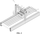
Fig. 2 is a schematic structural diagram of a code scanning system according to some embodiments of the present application; -
Fig. 3 is a schematic structural diagram of a code scanning system according to some embodiments of the present application; -
Fig. 4 is a schematic structural diagram of a code scanning system according to some embodiments of the present application; -
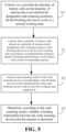
Fig. 5 is a schematic flow diagram of a material management method according to some embodiments of the present application; -
Fig. 6 is a schematic flow diagram of a material management method according to some embodiments of the present application; -
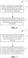
Fig. 7 is a schematic flow diagram of a material management method according to some embodiments of the present application; -
Fig. 8 is a schematic flow diagram of a material management method according to some embodiments of the present application; -
Fig. 9 is a schematic flow diagram of a material management method according to some embodiments of the present application; -
Fig. 10 is a schematic flow diagram of a material management method according to some embodiments of the present application; -
Fig. 11 is a schematic diagram of modules of a material management apparatus according to some embodiments of the present application; -
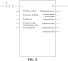
Fig. 12 is a schematic diagram of a program implementation according to some embodiments of the present application; -
Fig. 13 is a schematic diagram of a visual interface according to some embodiments of the present application; and -
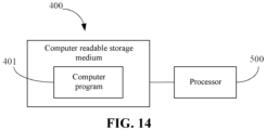
Fig. 14 is a schematic diagram of a connection state of a computer readable storage medium and a processor according to some embodiments of the present application. - Embodiments of the technical solutions of the present application will be described in detail below in conjunction with the drawings. The following embodiments are only used to more clearly illustrate the technical solutions of the present application, and therefore are only used as examples and cannot be used to limit the scope of protection of the present application.
- Unless otherwise defined, all technical and scientific terms used herein have the same meaning as commonly understood by those skilled in the art belonging to the technical field of the present application; the terms used herein are intended only for the purpose of describing specific embodiments and are not intended to limit the present application; the terms "including" and "having" and any variations thereof in the specification and the claims of the present application and in the description of drawings above are intended to cover non-exclusive inclusion.
- In the description of the embodiments of the present application, the technical terms "first", "second", and the like are used only to distinguish between different objects, and are not to be understood as indicating or implying a relative importance or implicitly specifying the number, particular order, or primary and secondary relation of the technical features indicated. In the description of the embodiments of the present application, the meaning of "a plurality of' is two or more, unless otherwise explicitly and specifically defined.
- Reference herein to "an embodiment" means that a particular feature, structure, or characteristic described in connection with the embodiment can be included in at least one embodiment of the present application. The phrase appearing in various positions in the specification does not necessarily refer to the same embodiment, nor is it an independent or alternative embodiment that is mutually exclusive with other embodiments. It is explicitly and implicitly understood by those skilled in the art that the embodiments described herein may be combined with other embodiments.
- In the description of the embodiments of the present application, the term "and/or" is only an association relationship for describing associated objects, indicating that there may be three relationships, for example A and/or B may represent three situations: A exists alone, both A and B exist, and B exists alone. In addition, the character "/" herein generally means that the associated objects before and after it are in an "or" relationship.
- In the description of the embodiments of the present application, the term "a plurality of' refers to two or more (including two), and similarly, "a plurality of groups" refers to two or more (including two) groups, and "a plurality of sheets" refers to two or more (including two) sheets.
- In the description of the embodiments of the present application, unless otherwise expressly specified and limited, the technical terms "mount," "join," "connect," "fix," etc. should be understood in a broad sense, such as, a fixed connection, a detachable connection, or an integral connection; a mechanical connection, or an electrical connection; a direct connection, an indirect connection through an intermediate medium, an internal connection of two elements, or interaction between two elements. For those of ordinary skill in the art, the specific meanings of the above terms in the embodiments of the present application can be understood according to specific situations.
- Batteries are an indispensable power source in daily life and industrial production, and the demand is very high. Therefore, production efficiency is an important factor affecting the profitability of battery manufacturers. In addition, the reliability of battery structures and performance is also a key factor determining whether a battery manufacturer has sustainable competitiveness and benefits. Therefore, in the battery production process, realizing the automatic processing and production of batteries and eliminating the influence of manual incorrect operation is an important way to improve the production efficiency and product reliability of batteries.
- In order to facilitate the traceability of information in follow-up links of batteries, in the production process of battery cells, outer surfaces of the battery cells are often sprayed with identifications such as barcodes and QR codes, and then an upper computer is used to transmit information such as a corresponding manufacturing process to the identifications. On a production line, each battery station has a corresponding code scanning device, which can be used to register and report the battery station, and then an upper computer will transmit process information correspondingly according to registration information. However, physical addresses or network addresses of the code scanning devices may be abnormal due to some reasons, such as manual replacement, resulting in errors in the reported station registration information of battery cells, which in turn leads to errors in the transmission of the relevant process information.
- Based on this, the applicant has designed a material management method for a battery production line after in-depth research. Before assigning information to identifications of battery cells, corresponding relationships between code scanning devices and stations are checked one by one through relevant mechanisms on the production line to ensure that the corresponding relationships between the code scanning devices and the stations are correct, and the station information of the battery cells can be reported accurately, so that it is ensured that an upper computer can transmit relevant process manufacturing information to the corresponding battery cells according to the station information.
- The battery cells disclosed in embodiments of the present application can be used in electrical apparatuses using batteries as power sources or in various energy storage systems using batteries as energy storage elements. The electrical apparatuses may be, but are not limited to, a mobile phone, a tablet, a laptop, an electric toy, an electric tool, a battery vehicle, an electric vehicle, a ship, a spacecraft, and so on. The electric toy may include fixed or mobile electric toys, such as game consoles, electric car toys, electric ship toys, and electric airplane toys. The spacecraft may include airplanes, rockets, space shuttles, spaceships, and the like. In the following embodiments, for the convenience of description, the electrical apparatus is a vehicle. The vehicle may be a fuel vehicle, a gas vehicle, or a new energy vehicle, and the new energy vehicle may be an all-electric vehicle, a hybrid vehicle, or an extended-range electric vehicle. The interior of the vehicle is provided with a battery, and the battery may be provided at the bottom or head or tail of the vehicle. The battery may be used to power the vehicle. For example, the battery may be used as an operating power source of the vehicle. The vehicle may further include a controller and a motor. The controller is used to control the battery to power the motor. For example, the controller is used for meeting the operating power demand when the vehicle is starting, navigating and driving. In addition, the battery may also be used as a driving power source of the vehicle to replace or partially replace fuel or natural gas to provide driving power for the vehicle.
- Referring to
Fig. 1 , the present application provides a material management method for a battery production line, including the following steps: - 01: controlling, after a plurality of battery cells placed on a plurality of stations reach designated code scanning positions, each blocking device to work in a first working state according to a predetermined sequence, thereby blocking identifications of the battery cells on the corresponding stations;
- 02: acquiring code scanning results of the code scanning devices corresponding to the blocking devices for the identifications when each blocking device works in the first working state respectively; and
- 03: determining, according to the code scanning results, whether a binding relationship between the code scanning devices and the stations is abnormal.
- Specifically, referring to
FIGS. 2-4 , the method of the present application is used for the battery production line, and acode scanning system 100 is disposed on the battery production line. The production line includes the plurality ofstations 101, and the code scanning system is configured with theblocking device 102 corresponding to eachstation 101 and thecode scanning device 103 bound to each station. - The code scanning system is tooling installed on the battery production line. The code scanning system includes a
gantry frame 104, a fixedbracket 105 is installed on thegantry frame 104, the fixed bracket includes a plurality of fixed connecting rods, one of the fixed connecting rods is equipped with a mountingsheet metal 106, and the mountingsheet metal 106 is used to install thecode scanning devices 103, wherein the number of thecode scanning devices 103 corresponds to the number of thestations 101, and in one example, eachstation 101 corresponds to onecode scanning device 103. - The
code scanning devices 103 are disposed towards the top walls of thebattery cells 200, and the top walls of thebattery cells 200 are attached with the identifications, which may be a QR code, a barcode, or the like. When thebattery cells 200 move following the production line to the designated code scanning positions, the identifications should be within the field of view of thecode scanning devices 103. The designated code scanning positions are the positions where the identifications can be recognized by thecode scanning devices 103. Thegantry frame 104 in the present application is also equipped with a mountingplate 107, the mountingplate 107 is used to installbattery blocking cylinders 108 and blockingstrips 109, and thebattery blocking cylinders 108 drive the blockingstrips 109 up and down under the drive of corresponding air sources, thereby blocking or releasing thebattery cells 200 on thestations 101. In actual operations, thebattery blocking cylinders 108 are usually in an extended state, and are blocked when thebattery cells 200 move to the positions of the blocking strips 109 along the assembly line. Thecode scanning system 100 may also be equipped with sensors, such as a photoelectric sensor. According to detection signals of the sensors, it can be known that thebattery cells 200 are in place, and thecode scanning devices 103 can perform a code scanning operation. - In the present application, the
blocking device 102 is further configured on the side of eachcode scanning device 103 close to thebattery cell 200, and theblocking device 102 may also be fixedly installed on the mounting sheet metal. Each blockingdevice 102 may include a cylinder and a blocking element. The blockingdevices 102 are communicated with the corresponding air sources, and the air sources drive the cylinders to drive the blocking elements to switch between the first working state and a second working state. When the blocking elements or the blockingdevices 102 are in the first working state, the blocking elements extend out to block thecode scanning devices 103, and thecode scanning devices 103 cannot normally scan the identifications of thebattery cells 200 on thestations 101. When the blocking elements or the blockingdevices 102 are in the second working state, the blocking elements retract and do not block thecode scanning devices 103, and thecode scanning devices 103 can normally scan the identifications of thebattery cells 200 on thestations 101. - It can be understood that the blocking elements are driven by the cylinders, and in order to ensure that the blocking
devices 102 on eachstation 101 can work according to the predetermined sequence, it is necessary to correctly connect the air sources and the cylinders through air pipes. In order to prevent possible replacement of the air pipes, the foolproofing of the air pipes can be realized through the fixed connecting rods. Specifically, arc via holes corresponding to the blockingdevices 102 may be formed in the fixed connecting rods. Each cylinder corresponds to two air pipes, and the two air pipes are connected to an air inlet port and an air outlet port of the cylinder respectively. Each air pipe penetrates through the corresponding arc via hole, one end is connected to the air source, and the other end is connected to the corresponding port on the cylinder. Preferably, the fixed connecting rods may also be sleeved with foolproofing rods, the foolproofing rods are also provided with arc via holes, and the radius of the arc via holes may be slightly smaller than the diameter of the air pipes, so that the air pipes may be clamped through the arc via holes. After the connection of the air pipes is completed, the foolproofing rods and the fixed connecting rods may be locked with screws, and the locking screws may be further sealed as required to prevent the air pipes from being replaced. - In addition, the production line further includes a plurality of guide strips 110, and the guide strips 110 are disposed between the
battery cells 200 of theadjacent stations 101 and used to limit the movement of thebattery cells 200 on the production line. - In the present application, based on the configuration of the tooling of the production line described above, detection is performed before code scanning of the
battery cells 200 to ensure that the reported information of thestations 101 of thebattery cells 200 is correct. In order to improve work efficiency, the production line may divide the plurality ofstations 101 through the guide strips 110, and may transport the plurality ofbattery cells 200 at the same time, and scan codes for the plurality ofbattery cells 200 at one time. - The predetermined sequence is the sequence in which the
code scanning devices 103 are detected, for example, the detection sequence of thecode scanning devices 103 may be determined according to the sequence of thestations 101, of course, may also be determined according to the actual production conditions on thestations 101, for example, thebattery cells 200 are placed on a part of the plurality ofstations 101. - As described above, the first working state refers to that the blocking elements extend out to block the
code scanning devices 103, and when the blockingdevices 102 work in the first working state, thecode scanning devices 103 cannot normally scan the identifications of thebattery cells 200 on thestations 101. - In the conventional state, the blocking elements of all the blocking
devices 102 are in the second working state, namely retraction, the working state of the blockingdevices 102 corresponding to thecode scanning devices 103 currently in the detection state is controlled to switch according to the detection requirements, and the blocking devices are switched from the second working state to the first working state in which the blocking elements extend out. According to the code scanning results of thecode scanning devices 103 when the blockingdevices 102 work in the first working state, whether a binding relationship between thecode scanning devices 103 and thestations 101 is abnormal is confirmed. Subsequent operations may be performed after thecode scanning devices 103 of all thestations 101 have been detected, namely the detection process is ended. - It is understandable that the possible reasons for errors in reported information of the
stations 101 include the following situations: - I. The mechanical positions or real physical addresses of the
code scanning devices 103 bound to thestations 101 are exchanged. For example, if thecode scanning device 103 originally corresponding to thestation 1 is exchanged to thestation 2, then what thecode scanning device 103 scans will be the identification of thebattery cell 200 located at thestation 2, and after the station information is reported to the upper computer, the upper computer still thinks that the information comes from thestation 1 according to the IP address of the station information, so it transmits the process manufacturing information corresponding to thestation 1 to thebattery cell 200 at thestation 2, resulting in information transmission errors of thebattery cell 200. However, if thecode scanning devices 103 on the production line are exchanged irregularly on a large scale, it will result in information abnormalities of thebattery cells 200 in batches. - II. The IP addresses of the
code scanning devices 103 bound to thestations 101 are exchanged. For example, if the IP address of thecode scanning device 103 corresponding to thestation 1 is exchanged to thecode scanning device 103 at thestation 2, then although what thecode scanning device 103 scans is still the identification of thebattery cell 200 located at thestation 1, after the station information is reported to the upper computer, the upper computer will think that the information comes from thestation 2 according to the IP address of the station information, so it transmits the process manufacturing information corresponding to thestation 2 to thebattery cell 200 at thestation 1, resulting in information transmission errors of thebattery cell 200. However, if the IP addresses of thecode scanning devices 103 on the production line are exchanged irregularly on a large scale, it will result in information abnormalities of thebattery cells 200 in batches. - In the present application, the
code scanning devices 103 are blocked by the blockingdevices 102, and then according to the code scanning results of thecode scanning devices 103 in the blocked state, whether the mechanical positions or IP addresses of thecode scanning devices 103 are exchanged is judged. Possible abnormalities can be detected early and processed in time to ensure normal production. - To sum up, in the present application, before the information transmission of the
battery cells 200, the position information of thecode scanning devices 103 is pre-detected by using theblocking devices 102 on the production line, thecode scanning devices 103 are blocked by the blockingdevices 102, and then according to the code scanning results of thecode scanning devices 103 in the blocked state, whether the positions of thecode scanning devices 103 are exchanged is judged, so that possible abnormalities are found in time and dealt with in time to ensure that the information transmission of thebattery cells 200 is correct. - Referring to
Fig. 5 , in some embodiments, the method further includes the following steps:
04: controlling, in a case that the plurality ofbattery cells 200 on the plurality ofstations 101 have not reached the designated code scanning positions, all the blockingdevices 102 to work in the second working state. - Specifically, when the
battery cells 200 have not reached the designated code scanning positions, all the blockingdevices 102 are controlled to work in the second working state, and when the blockingdevices 102 work in the second working state, thecode scanning devices 103 are able to scan the identifications of thebattery cells 200. By controlling the intake and outlet states of the corresponding cylinders, the blocking elements of the blockingdevices 102 are in a retracted state, so that when thebattery cells 200 reach the designated positions, thecode scanning devices 103 can normally scan the two-dimensional identifications on thebattery cells 200, which facilitates initialization verification and other operations before detection. - In this way, before the
battery cells 200 reach the designated code scanning positions, the blockingdevices 102 are controlled to work in the second working state, which facilitates operations such as initialization detection of thecode scanning devices 103. - Referring to
Fig. 6 , in some embodiments,step 01 includes: - 011: controlling, according to the predetermined sequence, the blocking
devices 102 one by one to switch from the second working state to the first working state; and - 012: controlling
other blocking devices 102 other than the blockingdevice 102 working in the first working state to maintain the second working state. - Specifically, taking a control strategy of one
blocking device 102 as an example, when the plurality ofbattery cells 200 reach the designated code scanning positions, the blocking elements of the blockingdevices 102 are driven by the cylinders to extend out to block the correspondingcode scanning devices 103. At the same time, theother blocking devices 102 are controlled to maintain the second working state, so that the code scanning results of the blockedcode scanning device 103 and othercode scanning devices 103 are different. After the code scanning results are reported, thenext blocking device 102 is controlled to switch its working state to the first working state, and at the same time, thecurrent blocking device 102 is controlled to switch from the first working state to the second working state. Further, according to the predetermined sequence, such as the sequence of thestations 101, the blockingdevices 102 are controlled one by one to switch the working states, and the blocking elements are driven by the cylinders to extend out to block the correspondingcode scanning devices 103. - In this way, according to the predetermined sequence, the blocking
devices 102 are controlled one by one to switch the working state, so that the code scanning results of the blockedcode scanning device 103 and othercode scanning devices 103 are different, and then it is confirmed whether the position information of thecode scanning devices 103 is abnormal. - Referring to
Fig. 7 , in some embodiments,step 01 includes: - 013: controlling, after the plurality of
battery cells 200 placed on the plurality ofstations 101 reach the designated code scanning positions, thecode scanning devices 103 to perform initial code scanning verification; and - 014: controlling, after passing the initial code scanning verification, each blocking
device 102 to work in the first working state according to the predetermined sequence, thereby blocking the identifications of thebattery cells 200 on the correspondingstations 101. - Specifically, after the
battery cells 200 reach the designated code scanning positions, and before detection, initial code scanning verification is performed first. The purpose of the initial code scanning verification is to confirm whether eachcode scanning device 103 can work normally. As mentioned above, when thebattery cells 200 have not reached the designated code scanning positions, the blockingdevices 102 are in the second working state, that is, the blocking elements are in the retracted state. Before thebattery cells 200 reach the designated code scanning positions, and the blockingdevices 102 are controlled to switch the working state in sequence, depending on the blockingdevices 102 being in the second working state, the identification of eachbattery cell 200 is in the field of view of the correspondingcode scanning device 103. In this case, thecode scanning devices 103 are controlled to scan the identifications, in the process of initial code scanning verification, the binding relationship of code scanning is not considered, and attention is paid to whether eachcode scanning device 103 can scan the identifications normally, thereby eliminating the reason of possible faults of thecode scanning devices 103 if thecode scanning devices 103 cannot scan the identifications after the blockingdevices 102 switch the working state subsequently. After passing the initial code scanning verification and confirming that thecode scanning devices 103 can work normally, each blockingdevice 102 will be controlled one by one to switch the working state according to the predetermined sequence to detect the positions of thecode scanning devices 103. - In this way, before detecting the binding relationship between the
code scanning devices 103 and thestations 101, initial code scanning verification is performed on thecode scanning devices 103 to confirm whether eachcode scanning device 103 can scan the identifications normally, thereby eliminating the reason of possible faults of thecode scanning devices 103 if thecode scanning devices 103 cannot scan the identifications after the blockingdevices 102 switch the working state subsequently. - Referring to
Fig. 8 , in some embodiments,step 03 includes:
031: confirming, in a case that the code scanning results are a first result, that the binding relationship between thecode scanning devices 103 and thestations 101 is abnormal. - Specifically, the first result is a code scanning result that the
code scanning devices 103 corresponding to the blockingdevices 102 can scan codes normally in a case that the blockingdevices 102 work in the first working state, that is, the blocking elements extend out to block thecode scanning devices 103. It is understandable that, in a normal state, if thecode scanning devices 103 are blocked by thecorresponding blocking devices 102, the code scanning devices cannot scan the identifications on thecorresponding battery cells 200. In one example, when codes can be scanned normally, a code scanning result OK may be returned, and when code scanning is abnormal, a code scanning result NG is returned. That is to say, in the normal state, if thecode scanning devices 103 are blocked by thecorresponding blocking devices 102, the code scanning result returned by thecode scanning devices 103 should be NG. If the result returned at this time is OK, then there may be a situation where thecode scanning devices 103 are exchanged as described above, that is, the binding relationship between thecode scanning devices 103 and thestations 101 is abnormal. - In this way, in a case that the
code scanning devices 103 are blocked, but can still return the normal code scanning results, it is confirmed that the binding relationship between thecode scanning devices 103 and thestations 101 is abnormal. - Referring to
Fig. 9 , in some embodiments,step 03 includes:
032: confirming, in a case that the code scanning results are a second result, that the binding relationship between thecode scanning devices 103 and thestations 101 is normal. - Specifically, the second result is a code scanning result that the
code scanning devices 103 corresponding to the blockingdevices 102 cannot scan codes normally in a case that the blockingdevices 102 work in the first working state. It is understandable that, in a normal state, if thecode scanning devices 103 are blocked by thecorresponding blocking devices 102, the code scanning devices cannot scan the identifications on thecorresponding battery cells 200. In one example, when codes can be scanned normally, a code scanning result OK may be returned, and when code scanning is abnormal, a code scanning result NG is returned. That is to say, in the normal state, if thecode scanning devices 103 are blocked by thecorresponding blocking devices 102, the code scanning result returned by thecode scanning devices 103 should be NG. If the result returned at this time is NG, it can be considered that the binding relationship between thecode scanning devices 103 and thestations 101 is normal. - In this way, in a case that the
code scanning devices 103 are blocked, and return abnormal code scanning results, it is confirmed that the binding relationship between thecode scanning devices 103 and thestations 101 is normal. - Referring to
Fig. 10 , in some embodiments, the method further includes the following steps:
05: issuing an alarm prompt in a case that it is determined according to the code scanning results that the binding relationship between thecode scanning devices 103 and thestations 101 is abnormal. - Specifically, if it is confirmed that there is an abnormality according to the code scanning results, the alarm prompt can be issued and the production line will be suspended. According to the alarm prompt, relevant staff learn that there is an abnormality in the binding relationship between the
code scanning devices 103 and thestations 101, and can conduct related abnormality investigations to solve the abnormal situation in time. After inspection, detection is performed again, and production can resume after normality is confirmed. - In this way, when the binding relationship between the
code scanning devices 103 and thestations 101 is abnormal, the alarm prompt can be issued, so that the abnormal situation can be resolved in time to ensure the normal operation of the production line. - In the following, a 4-
station 101 production line is taken as an example to illustrate the material management method of the present application:
afterbattery cells 200 on fourstations 101 reach designated code scanning positions, initial code scanning verification is performed first, and after passing the initial code scanning verification, binding relationships betweencode scanning devices 103 and thestations 101 are detected one by one. First, ablocking device 102 of thestation 1 is controlled to block thebattery cell 200 at thestation 1, blockingdevices 102 ofother stations 101 remain in a retracted state, and thecode scanning device 103 of each station performs a code scanning operation and reports a code scanning operation result. Whether there is an abnormality is judged according to the code scanning result. Under normal circumstances, the code scanning result of thecode scanning device 103 at thestation 1 is NG, and the code scanning results of othercode scanning devices 103 are OK. If not, the binding relationships between thecode scanning devices 103 and thestations 101 are abnormal, an alarm prompt is issued and relevant staff perform maintenance. - Similarly, after the
code scanning device 103 of thestation 1 is detected, ablocking device 102 of thestation 2 is controlled to block thebattery cell 200 at thestation 2, devices ofother stations 101 remain in the retracted state, and thecode scanning device 103 of each station performs a code scanning operation and reports a code scanning operation result. Whether there is an abnormality is judged according to the code scanning result. Under normal circumstances, the code scanning result of thecode scanning device 103 at thestation 2 is NG, and the code scanning results of othercode scanning devices 103 are OK. - After the
code scanning device 103 of thestation 2 is detected, ablocking device 102 of thestation 3 is controlled to block thebattery cell 200 at thestation 3, devices of other stations remain in the retracted state, and thecode scanning device 103 of eachstation 101 performs a code scanning operation and reports a code scanning operation result. Whether there is an abnormality is judged according to the code scanning result. Under normal circumstances, the code scanning result of thecode scanning device 103 at thestation 3 is NG, and the code scanning results of othercode scanning devices 103 are OK. - After the
code scanning device 103 of thestation 3 is detected, ablocking device 102 of thestation 4 is controlled to block thebattery cell 200 at thestation 4, devices of other stations remain in the retracted state, and thecode scanning device 103 of eachstation 101 performs a code scanning operation and reports a code scanning operation result. Whether there is an abnormality is judged according to the code scanning result. Under normal circumstances, the code scanning result of thecode scanning device 103 at thestation 4 is NG, and the code scanning results of othercode scanning devices 103 are OK. - So far, the detection of all the
code scanning devices 103 is completed. - Referring to
Fig. 11 , the present application further provides amaterial management apparatus 300, including: a controllingmodule 301, an acquiringmodule 302 and aprocessing module 303. Thematerial management apparatus 300 is used for a battery production line. For relevant settings of the battery production line, please refer to the explanation above, which will not be repeated here. - The controlling
module 301 is configured to control, after a plurality of battery cells placed on a plurality of stations reach designated code scanning positions, each blocking device to work in a first working state according to a predetermined sequence, thereby blocking identifications of the battery cells on the corresponding stations. - The acquiring
module 302 is configured to acquire code scanning results of the code scanning devices corresponding to the blocking devices for the identifications when each blocking device works in the first working state respectively. - The
processing module 303 is configured to determine, according to the code scanning results, whether a binding relationship between the code scanning devices and the stations is abnormal. - In this way, in the present application, before the information transmission of the battery cells, position information of the code scanning devices is pre-detected by using the blocking devices on the production line, the code scanning devices are blocked by the blocking devices, and then according to the code scanning results of the code scanning devices in the blocked state, whether the positions of the code scanning devices are exchanged is judged, so that possible abnormalities are found in time and dealt with in time to ensure that the information transmission of the battery cells is correct.
- In some embodiments, the controlling
module 301 is further configured to:
control, in a case that the plurality of battery cells on the plurality of stations have not reached the designated code scanning positions, all the blocking devices to work in a second working state, wherein, when the blocking devices work in the second working state, the code scanning devices are able to scan the identifications of the battery cells. - In this way, before the battery cells reach the designated code scanning positions, the blocking devices are controlled to work in the second working state, which facilitates operations such as initialization detection of the code scanning devices.
- In some embodiments, the controlling
module 301 is configured to: - control, according to the predetermined sequence, the blocking devices one by one to switch from the second working state to the first working state; and
- control other blocking devices other than the blocking devices working in the first working state to maintain the second working state.
- In this way, according to the predetermined sequence, the blocking devices are controlled one by one to switch the working state, so that the code scanning results of the blocked code scanning devices and other code scanning devices are different, and then it is confirmed whether the position information of the code scanning devices is abnormal.
- In some embodiments, the controlling
module 301 is configured to: - control, after the plurality of battery cells placed on the plurality of stations reach the designated code scanning positions, the code scanning devices to perform initial code scanning verification; and
- control, after passing the initial code scanning verification, each blocking device to work in the first working state according to the predetermined sequence, thereby blocking the identifications of the battery cells on the corresponding stations.
- In this way, before detecting the binding relationship between the code scanning devices and the stations, initial code scanning verification is performed on the code scanning devices to confirm whether each code scanning device can scan the identifications normally, thereby eliminating the reason of possible faults of the code scanning devices if the code scanning devices cannot scan the identifications after the blocking devices switch the working state subsequently.
- In some embodiments, the
processing module 303 is configured to:
confirm, in a case that the code scanning results are a first result, that the binding relationship between the code scanning devices and the stations is abnormal, the first result being a code scanning result that the code scanning devices corresponding to the blocking devices are able to scan codes normally in a case that the blocking devices work in the first working state. - In this way, in a case that the code scanning devices are blocked, but can still return the normal code scanning results, it is confirmed that the binding relationship between the code scanning devices and the stations is abnormal.
- In some embodiments, the
processing module 303 is configured to:
confirm, in a case that the code scanning results are a second result, that the binding relationship between the code scanning devices and the stations is normal, the second result being a code scanning result that the code scanning devices corresponding to the blocking devices are not able to scan codes normally in a case that the blocking devices work in the first working state. - In this way, in a case that the code scanning devices are blocked, and return abnormal code scanning results, it is confirmed that the binding relationship between the code scanning devices and the stations is normal.
- In some embodiments, the
apparatus 300 further includes an alarm module, which is configured to:
issue an alarm prompt in a case that it is determined according to the code scanning results that the binding relationship between the code scanning devices and the stations is abnormal. - In this way, when the binding relationship between the code scanning devices and the stations is abnormal, the alarm prompt can be issued, so that the abnormal situation can be resolved in time to ensure the normal operation of the production line.
- Each module in the above
material management apparatus 100 may be implemented entirely or partially through software, hardware, or a combination thereof. The modules above may be embedded into or independent of a processor in a computer device in a hardware form, or may be stored in a memory in the computer device in a software form, to facilitate calling of the processor to execute operations corresponding to the modules above. - The present application further provides a computer device, including a memory and a processor. A computer program is stored in the memory, and the processor implements the material management method provided by any embodiment above when executing the computer program.
- The implementation principle and technical effect of the computer device provided in the foregoing embodiment are similar to those of the foregoing method embodiment, and will not be repeated here.
- As shown in
Fig. 12 , the computer device may be a programmable logic controller, and the above-mentioned material management method may be designed as an implementation form of a functional module, wherein input parameters may include: an enable signal EN, a battery cell in-place signal, a function shielding signal, a fault reset signal, a state signal of a code scanning device at each station, a start detection signal, etc. Output parameters may include: a state of each blocking device, a detection trigger of each code scanning device, a detection state, a detection result, and an abnormality alarm. - In addition, a visual design for controlling a detection flow may also be performed, as shown in
Fig. 13 . A visual interface includes information such as a state of the blocking device of each station, a code scanning result of the code scanning devices, detection start, function shielding, battery cell in-place information, and a detection result, so that relevant staff can conveniently learn the detection process and the state information according to the information in the visual interface. - Referring to
Fig. 14 , the present application further provides a computerreadable storage medium 400 containing acomputer program 401. When executed by one ormore processors 500, thecomputer program 401 causes the one ormore processors 500 to execute the material management method in any one of the above-mentioned embodiments. - The implementation principles and technical effects of the provided computer readable storage medium are similar to those of the above-mentioned method embodiment, and will not be repeated here.
- Those of ordinary skill in the art can understand that all or part of the process in the method of the above embodiments can be implemented by instructing the relevant hardware through a computer program. The computer program can be stored in a non-volatile computer-readable storage medium. When the computer program is executed, the processes of the embodiments of the above methods may be included. Any reference to a memory, a database or other media used in the various embodiments provided in the present application may include at least one of a non-volatile memory and a volatile memory. The non-volatile memory may include a read-only memory (ROM), magnetic tape, a floppy disk, a flash memory, an optical memory, a high-density embedded non-volatile memory, a resistive memory (ReRAM), a magnetoresistive random access memory (MRAM), a ferroelectric random access memory (FRAM), a phase change memory (PCM), a graphene memory, or the like. The volatile memory may include a random access memory (RAM), an external cache memory, or the like. As an explanation rather than limitation, the RAM may take various forms, such as a static random access memory (SRAM) or a dynamic random access memory (DRAM). The processor involved in the various embodiments provided in the present application may be a general-purpose processor, a central processing unit, a graphics processor, a digital signal processor, a programmable logic device, a data processing logic device based on quantum computing, and the like, but is not limited thereto.
- Finally, it should be noted that the above embodiments are merely used for illustrating rather than limiting the technical solutions of the present application. Although the present application has been described in detail with reference to the above various embodiments, those of ordinary skill in the art should understand that the technical solutions specified in the above various embodiments can still be modified, or some or all of the technical features therein can be equivalently substituted; and such modifications or substitutions do not make the essence of the corresponding technical solutions depart from the scope of the technical solutions of the various embodiments of the present application, which shall fall within the scope of the claims and the specification of the present application. In particular, the technical features mentioned in the various embodiments can be combined in any manner as long as there is no structural conflict. The present application is not limited to the specific embodiments disclosed herein, but rather includes all technical solutions falling within the scope of the claims.
Claims (10)
- A material management method, applied to a battery production line, wherein the battery production line is provided with a code scanning system, the production line comprises a plurality of stations, the code scanning system is configured with a blocking device corresponding to each station and a code scanning device bound to each station, and the method comprises:controlling, after a plurality of battery cells placed on the plurality of stations reach designated code scanning positions, each blocking device to work in a first working state according to a predetermined sequence, thereby blocking identifications of the battery cells on the corresponding stations;acquiring code scanning results of the code scanning devices corresponding to the blocking devices for the identifications when each blocking device works in the first working state respectively; anddetermining, according to the code scanning results, whether a binding relationship between the code scanning devices and the stations is abnormal.
- The method according to claim 1, comprising:
controlling, in a case that the plurality of battery cells on the plurality of stations have not reached the designated code scanning positions, all the blocking devices to work in a second working state, wherein, when the blocking devices work in the second working state, the code scanning devices are able to scan the identifications of the battery cells. - The method according to claim 2, wherein the controlling, after a plurality of battery cells placed on the plurality of stations reach designated code scanning positions, each blocking device to work in a first working state according to a predetermined sequence, thereby blocking identifications of the battery cells on the corresponding stations, comprises:controlling, according to the predetermined sequence, the blocking devices one by one to switch from the second working state to the first working state; andcontrolling other blocking devices other than the blocking devices working in the first working state to maintain the second working state.
- The method according to claim 1, wherein the controlling, after a plurality of battery cells placed on the plurality of stations reach designated code scanning positions, each blocking device to work in a first working state according to a predetermined sequence, thereby blocking identifications of the battery cells on the corresponding stations, comprises:controlling, after the plurality of battery cells placed on the plurality of stations reach the designated code scanning positions, the code scanning devices to perform initial code scanning verification; andcontrolling, after passing the initial code scanning verification, each blocking device to work in the first working state according to the predetermined sequence, thereby blocking the identifications of the battery cells on the corresponding stations.
- The method according to claim 1, wherein the determining, according to the code scanning results, whether a binding relationship between the code scanning devices and the stations is abnormal, comprises:
confirming, in a case that the code scanning results are a first result, that the binding relationship between the code scanning devices and the stations is abnormal, the first result being a code scanning result that the code scanning devices corresponding to the blocking devices are able to scan codes normally in a case that the blocking devices work in the first working state. - The method according to claim 5, wherein the determining, according to the code scanning results, whether a binding relationship between the code scanning devices and the stations is abnormal, comprises:
confirming, in a case that the code scanning results are a second result, that the binding relationship between the code scanning devices and the stations is normal, the second result being a code scanning result that the code scanning devices corresponding to the blocking devices are not able to scan codes normally in a case that the blocking devices work in the first working state. - The method according to claim 5, further comprising:
issuing an alarm prompt in a case that it is determined according to the code scanning results that the binding relationship between the code scanning devices and the stations is abnormal. - A material management apparatus, applied to a battery production line, wherein the battery production line is provided with a code scanning system, the production line comprises a plurality of stations, the code scanning system is configured with a blocking device corresponding to each station and a code scanning device bound to each station, and the material management apparatus comprises:a controlling module, configured to control, after a plurality of battery cells placed on the plurality of stations reach designated code scanning positions, each blocking device to work in a first working state according to a predetermined sequence, thereby blocking identifications of the battery cells on the corresponding stations;an acquiring module, configured to acquire code scanning results of the code scanning devices corresponding to the blocking devices for the identifications when each blocking device works in the first working state respectively; anda processing module, configured to determine, according to the code scanning results, whether a binding relationship between the code scanning devices and the stations is abnormal.
- A computer device, comprising a processor and a memory storing a computer program, which, when executed by the processor, implements the method according to any one of claims 1 to 7.
- A computer readable storage medium storing a computer program, which, when executed by one or more processors, implements the method according to any one of claims 1 to 7.
Applications Claiming Priority (2)
| Application Number | Priority Date | Filing Date | Title |
|---|---|---|---|
| CN202211386717.5A CN115841281B (en) | 2022-11-07 | 2022-11-07 | Material management method, device, computer equipment and storage medium |
| PCT/CN2023/081127 WO2024098608A1 (en) | 2022-11-07 | 2023-03-13 | Material management method and apparatus, computer device, and storage medium |
Publications (3)
| Publication Number | Publication Date |
|---|---|
| EP4394675A1 true EP4394675A1 (en) | 2024-07-03 |
| EP4394675A4 EP4394675A4 (en) | 2024-07-17 |
| EP4394675B1 EP4394675B1 (en) | 2025-02-26 |
Family
ID=90927522
Family Applications (1)
| Application Number | Title | Priority Date | Filing Date |
|---|---|---|---|
| EP23733195.4A Active EP4394675B1 (en) | 2022-11-07 | 2023-03-13 | Material management method and apparatus, computer device, and storage medium |
Country Status (3)
| Country | Link |
|---|---|
| US (1) | US12366845B2 (en) |
| EP (1) | EP4394675B1 (en) |
| ES (1) | ES3031886T3 (en) |
Families Citing this family (1)
| Publication number | Priority date | Publication date | Assignee | Title |
|---|---|---|---|---|
| CN118761561B (en) * | 2024-09-04 | 2025-04-25 | 港华能源创科(深圳)有限公司 | A perovskite battery production line control method and system |
Family Cites Families (17)
| Publication number | Priority date | Publication date | Assignee | Title |
|---|---|---|---|---|
| TWI245227B (en) | 2004-02-13 | 2005-12-11 | Hon Hai Prec Ind Co Ltd | System and method for automatically scanning bar code symbols |
| CN101114965A (en) | 2007-08-21 | 2008-01-30 | 当代天启技术(北京)有限公司 | Method and system for binding wireless terminal equipment and gateway in LAN |
| CN107342984A (en) | 2017-06-13 | 2017-11-10 | 浙江大华技术股份有限公司 | A kind of system, method and device for apparatus bound |
| CN107704182B (en) | 2017-09-29 | 2020-03-31 | 维沃移动通信有限公司 | Code scanning method and mobile terminal |
| CN111507434A (en) | 2019-01-31 | 2020-08-07 | 北京骑胜科技有限公司 | Information acquisition method and device, electronic equipment and computer readable storage medium |
| CN110837877A (en) | 2019-10-15 | 2020-02-25 | 格力电器(武汉)有限公司 | Complete machine bar code detection method, equipment and system |
| CN213069837U (en) * | 2020-09-30 | 2021-04-27 | 武汉大雁软件有限公司 | Code module is swept to electric core, yard device and electric core production line are swept to electric core |
| CN114979818A (en) | 2021-02-22 | 2022-08-30 | 罗伯特·博世有限公司 | Monitoring method of detection equipment and server |
| CN112990729B (en) | 2021-03-26 | 2024-04-02 | 重庆烯宇新材料科技有限公司 | Code scanning tracing interception operation system |
| CN113077221A (en) | 2021-04-22 | 2021-07-06 | 杭州银弹科技有限公司 | Transportation information binding method, transportation information binding device and transportation system |
| CN215100508U (en) * | 2021-06-03 | 2021-12-10 | 东莞市威盛自动化设备有限公司 | Quick yard structure of sweeping of cylinder battery |
| CN113407706A (en) | 2021-06-30 | 2021-09-17 | 未鲲(上海)科技服务有限公司 | Abnormal data acquisition method, device, equipment and storage medium |
| CN113688965B (en) | 2021-08-11 | 2023-10-20 | 深圳市佳康捷科技有限公司 | Automatic storage code scanning detection method and cargo management system |
| CN113962234B (en) | 2021-10-21 | 2024-10-18 | 广东电网有限责任公司江门供电局 | An automatic identification and scanning device for electric energy metering device and method thereof |
| CN114192443B (en) | 2021-12-03 | 2023-01-17 | 惠州市德赛电池有限公司 | Battery code spraying and sorting integrated system and method |
| CN114429146B (en) | 2021-12-27 | 2023-11-03 | 华人运通(江苏)技术有限公司 | Error-proofing control system for battery production operation |
| CN115270829B (en) | 2022-09-26 | 2023-01-06 | 中国信息通信研究院 | Code scanning capability determining system of code scanning equipment based on industrial internet identification analysis |
-
2023
- 2023-03-13 ES ES23733195T patent/ES3031886T3/en active Active
- 2023-03-13 EP EP23733195.4A patent/EP4394675B1/en active Active
- 2023-07-04 US US18/346,818 patent/US12366845B2/en active Active
Also Published As
| Publication number | Publication date |
|---|---|
| EP4394675A4 (en) | 2024-07-17 |
| EP4394675B1 (en) | 2025-02-26 |
| US20240152115A1 (en) | 2024-05-09 |
| ES3031886T3 (en) | 2025-07-11 |
| US12366845B2 (en) | 2025-07-22 |
Similar Documents
| Publication | Publication Date | Title |
|---|---|---|
| CN102147607B (en) | Flexible general production line and production method of electronic product | |
| CN115841281B (en) | Material management method, device, computer equipment and storage medium | |
| US12366845B2 (en) | Material management method and apparatus, computer device, and storage medium | |
| CN216286300U (en) | Intelligent automatic production line control system | |
| US12217207B2 (en) | Scheduling method, apparatus, system, electronic device, and storage medium | |
| CN217493325U (en) | Full-automatic screw locking equipment | |
| CN206460293U (en) | A kind of cartridge-type charging and discharging mechanism and its control device | |
| CN113223978A (en) | Wafer cluster failure alarm method and alarm system | |
| US12358129B2 (en) | Transport apparatus and control method thereof | |
| CN111230316A (en) | Full-automatic lithium ion battery coding machine | |
| CN202863408U (en) | Battery exchanging monitoring system of electric car | |
| CN202494765U (en) | Integral tool for scanning and testing lithium ion battery | |
| CN105278441A (en) | Data interaction system | |
| CN114815699B (en) | Systems and methods for testing robot safety boards | |
| CN104309814B (en) | It is applied to control system and the control method thereof of multipoint array-type flexible frock | |
| US20260056535A1 (en) | Battery servicing system for use in battery servicing station and method thereof | |
| WO2024041370A1 (en) | Aircraft state indication method, aircraft, and storage medium | |
| CN115351207A (en) | A control method for strip spring production line equipment | |
| CN107872245A (en) | A kind of unmasked automated detection method and system for concentrator bandwidth carrier module | |
| CN107862854A (en) | A kind of unmasked automated detection method and system for three-phase electric energy meter bandwidth carrier module | |
| CN115743661A (en) | Unmanned aerial vehicle battery replacement airport, unmanned aerial vehicle battery replacement method and storage medium | |
| CN210181448U (en) | State monitoring system for large-scale two-dimensional rotary table | |
| CN108458741B (en) | Self-diagnosis method and system of leakage-proof sensor | |
| CN221891094U (en) | Calibration systems and robotic arc welding equipment | |
| CN118052508B (en) | Cross-library linkage system, method and computer equipment |
Legal Events
| Date | Code | Title | Description |
|---|---|---|---|
| STAA | Information on the status of an ep patent application or granted ep patent |
Free format text: STATUS: UNKNOWN |
|
| STAA | Information on the status of an ep patent application or granted ep patent |
Free format text: STATUS: THE INTERNATIONAL PUBLICATION HAS BEEN MADE |
|
| PUAI | Public reference made under article 153(3) epc to a published international application that has entered the european phase |
Free format text: ORIGINAL CODE: 0009012 |
|
| STAA | Information on the status of an ep patent application or granted ep patent |
Free format text: STATUS: REQUEST FOR EXAMINATION WAS MADE |
|
| 17P | Request for examination filed |
Effective date: 20230630 |
|
| AK | Designated contracting states |
Kind code of ref document: A1 Designated state(s): AL AT BE BG CH CY CZ DE DK EE ES FI FR GB GR HR HU IE IS IT LI LT LU LV MC ME MK MT NL NO PL PT RO RS SE SI SK SM TR |
|
| A4 | Supplementary search report drawn up and despatched |
Effective date: 20240614 |
|
| RIC1 | Information provided on ipc code assigned before grant |
Ipc: G06Q 10/10 20230101ALI20240610BHEP Ipc: G06K 17/00 20060101ALI20240610BHEP Ipc: G06Q 10/08 20240101AFI20240610BHEP |
|
| RAP1 | Party data changed (applicant data changed or rights of an application transferred) |
Owner name: CONTEMPORARY AMPEREX TECHNOLOGY(HONG KONG) LIMITED |
|
| GRAP | Despatch of communication of intention to grant a patent |
Free format text: ORIGINAL CODE: EPIDOSNIGR1 |
|
| STAA | Information on the status of an ep patent application or granted ep patent |
Free format text: STATUS: GRANT OF PATENT IS INTENDED |
|
| DAV | Request for validation of the european patent (deleted) | ||
| DAX | Request for extension of the european patent (deleted) | ||
| INTG | Intention to grant announced |
Effective date: 20241206 |
|
| GRAS | Grant fee paid |
Free format text: ORIGINAL CODE: EPIDOSNIGR3 |
|
| GRAA | (expected) grant |
Free format text: ORIGINAL CODE: 0009210 |
|
| STAA | Information on the status of an ep patent application or granted ep patent |
Free format text: STATUS: THE PATENT HAS BEEN GRANTED |
|
| AK | Designated contracting states |
Kind code of ref document: B1 Designated state(s): AL AT BE BG CH CY CZ DE DK EE ES FI FR GB GR HR HU IE IS IT LI LT LU LV MC ME MK MT NL NO PL PT RO RS SE SI SK SM TR |
|
| REG | Reference to a national code |
Ref country code: GB Ref legal event code: FG4D |
|
| REG | Reference to a national code |
Ref country code: CH Ref legal event code: EP |
|
| REG | Reference to a national code |
Ref country code: DE Ref legal event code: R096 Ref document number: 602023002226 Country of ref document: DE |
|
| REG | Reference to a national code |
Ref country code: IE Ref legal event code: FG4D |
|
| PGFP | Annual fee paid to national office [announced via postgrant information from national office to epo] |
Ref country code: AT Payment date: 20250417 Year of fee payment: 3 |
|
| P01 | Opt-out of the competence of the unified patent court (upc) registered |
Free format text: CASE NUMBER: APP_19234/2025 Effective date: 20250422 |
|
| REG | Reference to a national code |
Ref country code: NL Ref legal event code: MP Effective date: 20250226 |
|
| PG25 | Lapsed in a contracting state [announced via postgrant information from national office to epo] |
Ref country code: RS Free format text: LAPSE BECAUSE OF FAILURE TO SUBMIT A TRANSLATION OF THE DESCRIPTION OR TO PAY THE FEE WITHIN THE PRESCRIBED TIME-LIMIT Effective date: 20250526 |
|
| PG25 | Lapsed in a contracting state [announced via postgrant information from national office to epo] |
Ref country code: FI Free format text: LAPSE BECAUSE OF FAILURE TO SUBMIT A TRANSLATION OF THE DESCRIPTION OR TO PAY THE FEE WITHIN THE PRESCRIBED TIME-LIMIT Effective date: 20250226 |
|
| PG25 | Lapsed in a contracting state [announced via postgrant information from national office to epo] |
Ref country code: PL Free format text: LAPSE BECAUSE OF FAILURE TO SUBMIT A TRANSLATION OF THE DESCRIPTION OR TO PAY THE FEE WITHIN THE PRESCRIBED TIME-LIMIT Effective date: 20250226 |
|
| REG | Reference to a national code |
Ref country code: LT Ref legal event code: MG9D |
|
| REG | Reference to a national code |
Ref country code: ES Ref legal event code: FG2A Ref document number: 3031886 Country of ref document: ES Kind code of ref document: T3 Effective date: 20250711 |
|
| PG25 | Lapsed in a contracting state [announced via postgrant information from national office to epo] |
Ref country code: IS Free format text: LAPSE BECAUSE OF FAILURE TO SUBMIT A TRANSLATION OF THE DESCRIPTION OR TO PAY THE FEE WITHIN THE PRESCRIBED TIME-LIMIT Effective date: 20250626 Ref country code: NO Free format text: LAPSE BECAUSE OF FAILURE TO SUBMIT A TRANSLATION OF THE DESCRIPTION OR TO PAY THE FEE WITHIN THE PRESCRIBED TIME-LIMIT Effective date: 20250526 |
|
| PG25 | Lapsed in a contracting state [announced via postgrant information from national office to epo] |
Ref country code: NL Free format text: LAPSE BECAUSE OF FAILURE TO SUBMIT A TRANSLATION OF THE DESCRIPTION OR TO PAY THE FEE WITHIN THE PRESCRIBED TIME-LIMIT Effective date: 20250226 |
|
| PG25 | Lapsed in a contracting state [announced via postgrant information from national office to epo] |
Ref country code: HR Free format text: LAPSE BECAUSE OF FAILURE TO SUBMIT A TRANSLATION OF THE DESCRIPTION OR TO PAY THE FEE WITHIN THE PRESCRIBED TIME-LIMIT Effective date: 20250226 |
|
| PG25 | Lapsed in a contracting state [announced via postgrant information from national office to epo] |
Ref country code: PT Free format text: LAPSE BECAUSE OF FAILURE TO SUBMIT A TRANSLATION OF THE DESCRIPTION OR TO PAY THE FEE WITHIN THE PRESCRIBED TIME-LIMIT Effective date: 20250626 Ref country code: LV Free format text: LAPSE BECAUSE OF FAILURE TO SUBMIT A TRANSLATION OF THE DESCRIPTION OR TO PAY THE FEE WITHIN THE PRESCRIBED TIME-LIMIT Effective date: 20250226 |
|
| PG25 | Lapsed in a contracting state [announced via postgrant information from national office to epo] |
Ref country code: BG Free format text: LAPSE BECAUSE OF FAILURE TO SUBMIT A TRANSLATION OF THE DESCRIPTION OR TO PAY THE FEE WITHIN THE PRESCRIBED TIME-LIMIT Effective date: 20250226 Ref country code: GR Free format text: LAPSE BECAUSE OF FAILURE TO SUBMIT A TRANSLATION OF THE DESCRIPTION OR TO PAY THE FEE WITHIN THE PRESCRIBED TIME-LIMIT Effective date: 20250527 |
|
| REG | Reference to a national code |
Ref country code: HU Ref legal event code: AG4A Ref document number: E071104 Country of ref document: HU |
|
| PG25 | Lapsed in a contracting state [announced via postgrant information from national office to epo] |
Ref country code: SE Free format text: LAPSE BECAUSE OF FAILURE TO SUBMIT A TRANSLATION OF THE DESCRIPTION OR TO PAY THE FEE WITHIN THE PRESCRIBED TIME-LIMIT Effective date: 20250226 |
|
| PG25 | Lapsed in a contracting state [announced via postgrant information from national office to epo] |
Ref country code: SM Free format text: LAPSE BECAUSE OF FAILURE TO SUBMIT A TRANSLATION OF THE DESCRIPTION OR TO PAY THE FEE WITHIN THE PRESCRIBED TIME-LIMIT Effective date: 20250226 |
|
| PG25 | Lapsed in a contracting state [announced via postgrant information from national office to epo] |
Ref country code: DK Free format text: LAPSE BECAUSE OF FAILURE TO SUBMIT A TRANSLATION OF THE DESCRIPTION OR TO PAY THE FEE WITHIN THE PRESCRIBED TIME-LIMIT Effective date: 20250226 |
|
| PG25 | Lapsed in a contracting state [announced via postgrant information from national office to epo] |
Ref country code: IT Free format text: LAPSE BECAUSE OF FAILURE TO SUBMIT A TRANSLATION OF THE DESCRIPTION OR TO PAY THE FEE WITHIN THE PRESCRIBED TIME-LIMIT Effective date: 20250226 |
|
| PG25 | Lapsed in a contracting state [announced via postgrant information from national office to epo] |
Ref country code: AT Free format text: LAPSE BECAUSE OF FAILURE TO SUBMIT A TRANSLATION OF THE DESCRIPTION OR TO PAY THE FEE WITHIN THE PRESCRIBED TIME-LIMIT Effective date: 20250226 |
|
| PG25 | Lapsed in a contracting state [announced via postgrant information from national office to epo] |
Ref country code: CZ Free format text: LAPSE BECAUSE OF FAILURE TO SUBMIT A TRANSLATION OF THE DESCRIPTION OR TO PAY THE FEE WITHIN THE PRESCRIBED TIME-LIMIT Effective date: 20250226 Ref country code: EE Free format text: LAPSE BECAUSE OF FAILURE TO SUBMIT A TRANSLATION OF THE DESCRIPTION OR TO PAY THE FEE WITHIN THE PRESCRIBED TIME-LIMIT Effective date: 20250226 |
|
| PG25 | Lapsed in a contracting state [announced via postgrant information from national office to epo] |
Ref country code: RO Free format text: LAPSE BECAUSE OF FAILURE TO SUBMIT A TRANSLATION OF THE DESCRIPTION OR TO PAY THE FEE WITHIN THE PRESCRIBED TIME-LIMIT Effective date: 20250226 |
|
| PG25 | Lapsed in a contracting state [announced via postgrant information from national office to epo] |
Ref country code: SK Free format text: LAPSE BECAUSE OF FAILURE TO SUBMIT A TRANSLATION OF THE DESCRIPTION OR TO PAY THE FEE WITHIN THE PRESCRIBED TIME-LIMIT Effective date: 20250226 |
|
| PG25 | Lapsed in a contracting state [announced via postgrant information from national office to epo] |
Ref country code: LU Free format text: LAPSE BECAUSE OF NON-PAYMENT OF DUE FEES Effective date: 20250313 |
|
| REG | Reference to a national code |
Ref country code: DE Ref legal event code: R097 Ref document number: 602023002226 Country of ref document: DE |
|
| REG | Reference to a national code |
Ref country code: BE Ref legal event code: MM Effective date: 20250331 |
|
| PG25 | Lapsed in a contracting state [announced via postgrant information from national office to epo] |
Ref country code: MC Free format text: LAPSE BECAUSE OF FAILURE TO SUBMIT A TRANSLATION OF THE DESCRIPTION OR TO PAY THE FEE WITHIN THE PRESCRIBED TIME-LIMIT Effective date: 20250226 |
|
| PLBE | No opposition filed within time limit |
Free format text: ORIGINAL CODE: 0009261 |
|
| STAA | Information on the status of an ep patent application or granted ep patent |
Free format text: STATUS: NO OPPOSITION FILED WITHIN TIME LIMIT |
|
| PG25 | Lapsed in a contracting state [announced via postgrant information from national office to epo] |
Ref country code: BE Free format text: LAPSE BECAUSE OF NON-PAYMENT OF DUE FEES Effective date: 20250331 |
|
| PG25 | Lapsed in a contracting state [announced via postgrant information from national office to epo] |
Ref country code: IE Free format text: LAPSE BECAUSE OF NON-PAYMENT OF DUE FEES Effective date: 20250313 |
|
| 26N | No opposition filed |
Effective date: 20251127 |
|
| PGFP | Annual fee paid to national office [announced via postgrant information from national office to epo] |
Ref country code: DE Payment date: 20260324 Year of fee payment: 4 |
|
| PGFP | Annual fee paid to national office [announced via postgrant information from national office to epo] |
Ref country code: FR Payment date: 20260330 Year of fee payment: 4 |
|
| PG25 | Lapsed in a contracting state [announced via postgrant information from national office to epo] |
Ref country code: CY Free format text: LAPSE BECAUSE OF FAILURE TO SUBMIT A TRANSLATION OF THE DESCRIPTION OR TO PAY THE FEE WITHIN THE PRESCRIBED TIME-LIMIT Effective date: 20250226 |
|
| PG25 | Lapsed in a contracting state [announced via postgrant information from national office to epo] |
Ref country code: LT Free format text: LAPSE BECAUSE OF FAILURE TO SUBMIT A TRANSLATION OF THE DESCRIPTION OR TO PAY THE FEE WITHIN THE PRESCRIBED TIME-LIMIT Effective date: 20250226 |
|
| PG25 | Lapsed in a contracting state [announced via postgrant information from national office to epo] |
Ref country code: TR Free format text: LAPSE BECAUSE OF FAILURE TO SUBMIT A TRANSLATION OF THE DESCRIPTION OR TO PAY THE FEE WITHIN THE PRESCRIBED TIME-LIMIT Effective date: 20250226 |
|
| PGFP | Annual fee paid to national office [announced via postgrant information from national office to epo] |
Ref country code: ES Payment date: 20260401 Year of fee payment: 4 |