EP4394643A1 - Variable-stroke self-adaptive adjustment quasi-zero stiffness device and parameter checking method - Google Patents
Variable-stroke self-adaptive adjustment quasi-zero stiffness device and parameter checking method Download PDFInfo
- Publication number
- EP4394643A1 EP4394643A1 EP22860314.8A EP22860314A EP4394643A1 EP 4394643 A1 EP4394643 A1 EP 4394643A1 EP 22860314 A EP22860314 A EP 22860314A EP 4394643 A1 EP4394643 A1 EP 4394643A1
- Authority
- EP
- European Patent Office
- Prior art keywords
- quasi
- measuring instrument
- zero stiffness
- adjustment
- stiffness
- Prior art date
- Legal status (The legal status is an assumption and is not a legal conclusion. Google has not performed a legal analysis and makes no representation as to the accuracy of the status listed.)
- Pending
Links
Images

Classifications
-
- G—PHYSICS
- G06—COMPUTING OR CALCULATING; COUNTING
- G06F—ELECTRIC DIGITAL DATA PROCESSING
- G06F30/00—Computer-aided design [CAD]
- G06F30/20—Design optimisation, verification or simulation
-
- B—PERFORMING OPERATIONS; TRANSPORTING
- B64—AIRCRAFT; AVIATION; COSMONAUTICS
- B64G—COSMONAUTICS; VEHICLES OR EQUIPMENT THEREFOR
- B64G7/00—Simulating cosmonautic conditions, e.g. for conditioning crews
-
- G—PHYSICS
- G01—MEASURING; TESTING
- G01C—MEASURING DISTANCES, LEVELS OR BEARINGS; SURVEYING; NAVIGATION; GYROSCOPIC INSTRUMENTS; PHOTOGRAMMETRY OR VIDEOGRAMMETRY
- G01C21/00—Navigation; Navigational instruments not provided for in groups G01C1/00 - G01C19/00
- G01C21/02—Navigation; Navigational instruments not provided for in groups G01C1/00 - G01C19/00 by astronomical means
-
- G—PHYSICS
- G01—MEASURING; TESTING
- G01C—MEASURING DISTANCES, LEVELS OR BEARINGS; SURVEYING; NAVIGATION; GYROSCOPIC INSTRUMENTS; PHOTOGRAMMETRY OR VIDEOGRAMMETRY
- G01C21/00—Navigation; Navigational instruments not provided for in groups G01C1/00 - G01C19/00
- G01C21/24—Navigation; Navigational instruments not provided for in groups G01C1/00 - G01C19/00 specially adapted for cosmonautical navigation
-
- G—PHYSICS
- G01—MEASURING; TESTING
- G01M—TESTING STATIC OR DYNAMIC BALANCE OF MACHINES OR STRUCTURES; TESTING OF STRUCTURES OR APPARATUS, NOT OTHERWISE PROVIDED FOR
- G01M11/00—Testing of optical apparatus; Testing structures by optical methods not otherwise provided for
- G01M11/02—Testing optical properties
- G01M11/04—Optical benches therefor
-
- G—PHYSICS
- G06—COMPUTING OR CALCULATING; COUNTING
- G06F—ELECTRIC DIGITAL DATA PROCESSING
- G06F30/00—Computer-aided design [CAD]
- G06F30/20—Design optimisation, verification or simulation
- G06F30/23—Design optimisation, verification or simulation using finite element methods [FEM] or finite difference methods [FDM]
-
- G—PHYSICS
- G06—COMPUTING OR CALCULATING; COUNTING
- G06F—ELECTRIC DIGITAL DATA PROCESSING
- G06F2119/00—Details relating to the type or aim of the analysis or the optimisation
- G06F2119/14—Force analysis or force optimisation, e.g. static or dynamic forces
-
- Y—GENERAL TAGGING OF NEW TECHNOLOGICAL DEVELOPMENTS; GENERAL TAGGING OF CROSS-SECTIONAL TECHNOLOGIES SPANNING OVER SEVERAL SECTIONS OF THE IPC; TECHNICAL SUBJECTS COVERED BY FORMER USPC CROSS-REFERENCE ART COLLECTIONS [XRACs] AND DIGESTS
- Y02—TECHNOLOGIES OR APPLICATIONS FOR MITIGATION OR ADAPTATION AGAINST CLIMATE CHANGE
- Y02T—CLIMATE CHANGE MITIGATION TECHNOLOGIES RELATED TO TRANSPORTATION
- Y02T90/00—Enabling technologies or technologies with a potential or indirect contribution to GHG emissions mitigation
Definitions
- the spatial pointing measuring instrument can calculate the attitude information of the spacecraft or the pointing information of the spatial target by photoelectric imaging of stars or other spatial targets.
- the high-performance spacecraft requires the precision of the spatial pointing measuring instrument to be higher than 0.1 arc second, and the influence of the platform micro-vibration environment on the spatial pointing measuring instrument, which was neglected in the past, has attracted great attention.
- the sensitive optical element in the pointing measuring instrument with the extremely high precision is slightly disturbed, which will produce a tiny deformation, a rigid body displacement and even a higher-order deformation, thus affecting the pointing accuracy of the optical axis of the pointing measuring instrument.
- it is an effective means of detection and verification to study the micro-vibration problem of the pointing measuring instrument with the extremely high precision in the ground laboratory environment.
- the present disclosure aims at overcoming the defects in the related art, and providing a variable-stroke self-adaptive adjustment quasi-zero stiffness device and a parameter checking method of the same, which can comprehensively evaluate and quantitatively analyze the influence of a platform micro-vibration environment on a spatial pointing measuring instrument with an extremely high precision.
- a variable-stroke self-adaptive adjustment quasi-zero stiffness device includes: an integrating sphere, a target, a collimator, a pointing measuring instrument, a disturbance source, an inertia simulation tooling, a quasi-zero stiffness suspension adjustment device and an optical air-bearing platform.
- the integrating sphere, the target and the collimator are coaxially arranged on the optical air-bearing platform in sequence.
- the integrating sphere provides a light source, the target provides point target information, and the collimator simulates infinity.
- the pointing measuring instrument is an object to be tested, the inertia simulation tooling is a hollow cubic structure, and the pointing measuring instrument is connected and fixed with the inertia simulation tooling through a screw.
- the quasi-zero stiffness suspension adjustment device suspends the inertia simulation tooling to provide a free boundary environment.
- the quasi-zero stiffness suspension adjustment device, the pointing measuring instrument, the disturbance source and the inertia simulation tooling form a set of two-pendulum system as a whole.
- the inertia simulation tooling includes a mounting flange, and is connected with the pointing measuring instrument through the mounting flange, and a counterweight is mounted on a side surface of the inertia simulation tooling opposite to the pointing measuring instrument.
- the quasi-zero stiffness suspension adjustment device performs a direction adjustment of six degrees of freedom such that the pointing measuring instrument faces the collimator, wherein x, y and z are defined to represent three mutually perpendicular coordinate axis directions with a center of mass of the pointing measuring instrument as an origin, z is an optical axis direction, and U,V and W represent directions of degrees of freedom for rotation around the x, y and z axes, respectively.
- three disturbance sources are mounted on three surfaces of the inertia simulation tooling, respectively, and normals of the three disturbance sources are perpendicular to each other.
- the quasi-zero stiffness suspension adjustment device includes: a suspension crown block, high-stiffness suspenders, a -shaped tooling, a high-modulus and high-stiffness spring, a double-stroke bolt assembly and a first suspension point.
- the -shaped tooling is arranged horizontally, with four second suspension points at four corners of its upper end face and four third suspension points at four corners of its lower end face.
- the four second suspension points are respectively connected to the suspension crown block through the high-stiffness suspenders, and the four third suspension points are respectively connected to upper ends of corresponding high-modulus and high-stiffness springs under the -shaped tooling through the high-stiffness suspenders.
- Lower ends of four high-modulus and high-stiffness springs each are connected with the first suspension point through the double-stroke bolt assembly.
- a top of the inertia simulation tooling includes four hooks, which are respectively connected with four first suspension points at a lower end of the quasi-zero stiffness suspension adjustment device; and the double-stroke bolt assembly includes a two-sided nut frame and two M16 high-strength bolts.
- a parameter checking method of a variable-stroke self-adaptive adjustment quasi-zero stiffness device which includes: step 1, checking a quasi-zero stiffness frequency, where according to the two-pendulum system formed by the quasi-zero stiffness suspension adjustment device, the pointing measuring instrument, the disturbance source and the inertia simulation tooling as a whole, a dynamic equation of the two-pendulum system is established and solved to obtain a characteristic frequency of the variable-stroke self-adaptive adjustment quasi-zero stiffness device, i.e.
- the dynamic equation of the two-pendulum system is established by a Lagrangue equation method, and the equation is a second-order implicit differential equation set in two variables, and is solved by a Runge-Kutta numerical solution method to obtain the characteristic frequency of the device, i.e., the stiffness value of the variable-stroke self-adaptive adjustment quasi-zero stiffness device.
- L 1 is a length of a first swing arm of the two-pendulum system
- L 2 is a length of a second swing arm of the two-pendulum system
- m 1 is an equivalent mass point of the first swing arm of the two-pendulum system
- m 2 is an equivalent mass point of the second swing arm of the two-pendulum system
- g is a gravitational acceleration
- ⁇ 1 is an included angle between the first swing arm and the gravitational acceleration g
- ⁇ 2 is an included angle between the second swing arm and the gravitational acceleration g
- two dots on ⁇ 1 and ⁇ 2 represent a second derivative.
- a finite element analysis method is used to further check the quasi-zero stiffness frequency to determine whether its transverse characteristic frequency is consistent with a theoretical calculation result.
- checking the adjustment resolution specifically includes: calculating the adjustment resolution, where the adjustment of the pointing measuring instrument in the U and V directions and the position adjustment of the target on the focal plane of the pointing measuring instrument are realized through the double-stroke bolt assembly.
- Zu represents a pitch
- L ⁇ represents an effective length of the pointing measuring instrument of the two-pendulum system in the optical axis direction
- the adjustment resolution ⁇ u should not be greater than 0.5'.
- the target is adjusted to be within a field of view of the pointing measuring instrument through the double-stroke bolt assembly.
- the present disclosure provides a variable-stroke self-adaptive adjustment quasi-zero stiffness device and a parameter checking method of the same.
- the device is configured as a two-pendulum system, and a quasi-zero stiffness condition of an on-orbit free boundary condition is simulated in a ground laboratory environment through the variable-stroke self-adaptive adjustment quasi-zero stiffness device.
- the adjustment of pitch and yaw attitudes is creatively realized when the pointing measuring instrument is suspended, so that the target is aligned in the focal plane of the pointing measuring instrument.
- the key parameters of the zero stiffness device are effectively checked to ensure that the design of the zero stiffness device meets the requirements and the indexes are reliable.
- the present disclosure can comprehensively evaluate and quantitatively analyze the influence of the platform micro-vibration environment on the spatial pointing measuring instrument with the extremely high precision.
- the integrating sphere 10, the target 20 and the collimator 30 are coaxially mounted on the optical air-bearing platform 80 in sequence.
- the integrating sphere 10 provides a light source
- the target 20 provides point target information
- the collimator 30 simulates infinity.
- the pointing measuring instrument 40 is an object to be tested
- the inertia simulation tooling 60 has a hollow cubic structure
- the pointing measuring instrument 40 is connected and fixed with the inertia simulation tooling 60 through a screw.
- Three disturbance sources 50 are mounted on the inertia simulation tooling 60 to provide small disturbance and inertia for the pointing measuring instrument 40.
- the quasi-zero stiffness suspension adjustment device 70 suspends the inertia simulation tooling 60 to provide a free boundary environment.
- the -shaped tooling 703 is arranged horizontally, with four second suspension points 7031 at four corners of its upper end face and four third suspension points 7032 at four corners of its lower end face.
- the four second suspension points 7031 are respectively connected to the suspension crown block 701 through the high-stiffness suspenders 702, and the four third suspension points 7032 are respectively connected to upper ends of corresponding high-modulus and high-stiffness springs 704 under the -shaped tooling 703 through the high-stiffness suspenders 702.
- Lower ends of the four high-modulus and high-stiffness springs 704 are respectively connected to the first suspension points 706 through the double-stroke bolt assemblies 705.
- the quasi-zero stiffness suspension adjustment device 70 suspends the inertia simulation tooling 60 to provide the free boundary environment.
- the quasi-zero stiffness suspension adjustment device 70, the pointing measuring instrument 40, the disturbance source 50 and the inertia simulation tooling 60 form a set of two-pendulum system as a whole, and the basic characteristic frequencies of the two-pendulum system are 0.114 Hz and 0.295 Hz, respectively.
- the direction adjustment of six degrees of freedom of the pointing measuring instrument 40 is realized by the quasi-zero stiffness suspension adjustment device 70, so that the center of the pointing measuring instrument 40 is aligned with the axis of the collimator 30.
- the parameter checking is divided into quasi-zero stiffness checking and strength checking.
- the quasi-zero stiffness checking is to confirm that the designed device meets the quasi-zero stiffness condition and can meet the test requirements.
- the strength checking is to ensure the safety and reliability of the system, and avoid damages and potential safety hazards.
- a variable-stroke self-adaptive adjustment quasi-zero stiffness device is configured as a two-pendulum system, a dynamic equation of the two-pendulum system is established by the Lagrangue equation method, and the equation is a second-order implicit differential equation set in two variables, and is solved by the Runge-Kutta numerical solution method to obtain the characteristic frequency of the device, that is, the stiffness value of the variable-stroke self-adaptive adjustment quasi-zero stiffness device.
- the strength checking in the present disclosure mainly lies in the strength checking of the high-modulus and high-stiffness spring to ensure safety, and the strength checking mainly uses the strength checking calculation formula of the spring to check the shear stress of the spring wire.
- the adjustment of the pointing measuring instrument in the U and V directions and the position adjustment of the target on the focal plane of the pointing measuring instrument are realized through the double-stroke bolt assembly.
Landscapes
- Engineering & Computer Science (AREA)
- Physics & Mathematics (AREA)
- Remote Sensing (AREA)
- Theoretical Computer Science (AREA)
- General Physics & Mathematics (AREA)
- Radar, Positioning & Navigation (AREA)
- General Engineering & Computer Science (AREA)
- Computer Hardware Design (AREA)
- Evolutionary Computation (AREA)
- Geometry (AREA)
- Aviation & Aerospace Engineering (AREA)
- Automation & Control Theory (AREA)
- Astronomy & Astrophysics (AREA)
- Chemical & Material Sciences (AREA)
- Analytical Chemistry (AREA)
- Testing Of Devices, Machine Parts, Or Other Structures Thereof (AREA)
- Investigating Strength Of Materials By Application Of Mechanical Stress (AREA)
Abstract
Description
- The present disclosure claims the priority of
Chinese patent application No. 202110978217.X filed with China National Intellectual Property Administration on August 23, 2021 - The present disclosure relate to a field of micro-vibration tests and experiments of spatial pointing measuring instruments with extremely high precision, in particular to a variable-stroke self-adaptive adjustment quasi-zero stiffness device and a parameter checking method of the same.
- As the core component for the spacecraft attitude pointing measurement and the spatial target pointing measurement, the spatial pointing measuring instrument can calculate the attitude information of the spacecraft or the pointing information of the spatial target by photoelectric imaging of stars or other spatial targets. The high-performance spacecraft requires the precision of the spatial pointing measuring instrument to be higher than 0.1 arc second, and the influence of the platform micro-vibration environment on the spatial pointing measuring instrument, which was neglected in the past, has attracted great attention.
- The sensitive optical element in the pointing measuring instrument with the extremely high precision is slightly disturbed, which will produce a tiny deformation, a rigid body displacement and even a higher-order deformation, thus affecting the pointing accuracy of the optical axis of the pointing measuring instrument. At present, it is an effective means of detection and verification to study the micro-vibration problem of the pointing measuring instrument with the extremely high precision in the ground laboratory environment.
- The existing low-stiffness micro-vibration test methods mainly include a suspension method and an air bearing method, and the present disclosure belongs to the suspension method. Most of the existing suspension methods use a flexible rope or an elastic rope to obtain the low stiffness environment needed for the micro-vibration test, but its stiffness is still large and it does not have the ability of variable-stroke adjustment and alignment. The closest related arts to the present disclosure are "A new spacecraft on-orbit ultra-clean weightlessness environment simulation test system (
CN106477074 )", "A satellite micro-vibration test multipoint suspension system and its design method (CN103482088A )" and "A device for testing influence of satellite platform micro-vibration on camera imaging (CN105530514A )", all of which provide a suspension device, with all the tested objects being suspended by the flexible rope or the elastic rope, so as to meet the low stiffness environment required by the test. However, the stiffness of these three design methods is still relatively large, these three design methods do not have the ability of displacement adjustment and direction adjustment and alignment, and they do not have the ability of adjustment and alignment and quasi-zero stiffness required by the micro-vibration test of the spatial pointing measuring instrument with the extremely high precision. - Therefore, it is an urgent problem to design a simple, reliable, easy to operate, easy to mount and low-cost variable-stroke self-adaptive adjustment quasi-zero stiffness device and a parameter checking method of the same.
- The present disclosure aims at overcoming the defects in the related art, and providing a variable-stroke self-adaptive adjustment quasi-zero stiffness device and a parameter checking method of the same, which can comprehensively evaluate and quantitatively analyze the influence of a platform micro-vibration environment on a spatial pointing measuring instrument with an extremely high precision.
- The technical solution adopted by the present disclosure is as follows.
- A variable-stroke self-adaptive adjustment quasi-zero stiffness device includes: an integrating sphere, a target, a collimator, a pointing measuring instrument, a disturbance source, an inertia simulation tooling, a quasi-zero stiffness suspension adjustment device and an optical air-bearing platform. The integrating sphere, the target and the collimator are coaxially arranged on the optical air-bearing platform in sequence. The integrating sphere provides a light source, the target provides point target information, and the collimator simulates infinity. The pointing measuring instrument is an object to be tested, the inertia simulation tooling is a hollow cubic structure, and the pointing measuring instrument is connected and fixed with the inertia simulation tooling through a screw. Three disturbance sources are mounted on the inertia simulation tooling to provide small disturbance and inertia for the pointing measuring instrument. The quasi-zero stiffness suspension adjustment device suspends the inertia simulation tooling to provide a free boundary environment. The quasi-zero stiffness suspension adjustment device, the pointing measuring instrument, the disturbance source and the inertia simulation tooling form a set of two-pendulum system as a whole.
- Further, the inertia simulation tooling includes a mounting flange, and is connected with the pointing measuring instrument through the mounting flange, and a counterweight is mounted on a side surface of the inertia simulation tooling opposite to the pointing measuring instrument.
- Further, after the inertia simulation tooling is suspended, the quasi-zero stiffness suspension adjustment device performs a direction adjustment of six degrees of freedom such that the pointing measuring instrument faces the collimator, wherein x, y and z are defined to represent three mutually perpendicular coordinate axis directions with a center of mass of the pointing measuring instrument as an origin, z is an optical axis direction, and U,V and W represent directions of degrees of freedom for rotation around the x, y and z axes, respectively.
- Further, basic characteristic frequencies of the two-pendulum system are 0.114 Hz and 0.295 Hz, respectively.
- Further, three disturbance sources are mounted on three surfaces of the inertia simulation tooling, respectively, and normals of the three disturbance sources are perpendicular to each other.
- Further, the quasi-zero stiffness suspension adjustment device includes: a suspension crown block, high-stiffness suspenders, a-shaped tooling, a high-modulus and high-stiffness spring, a double-stroke bolt assembly and a first suspension point. The
 -shaped tooling is arranged horizontally, with four second suspension points at four corners of its upper end face and four third suspension points at four corners of its lower end face. The four second suspension points are respectively connected to the suspension crown block through the high-stiffness suspenders, and the four third suspension points are respectively connected to upper ends of corresponding high-modulus and high-stiffness springs under the-shaped tooling through the high-stiffness suspenders. Lower ends of four high-modulus and high-stiffness springs each are connected with the first suspension point through the double-stroke bolt assembly.
 - Further, a top of the inertia simulation tooling includes four hooks, which are respectively connected with four first suspension points at a lower end of the quasi-zero stiffness suspension adjustment device; and the double-stroke bolt assembly includes a two-sided nut frame and two M16 high-strength bolts.
- Further, the present disclosure provides a parameter checking method of a variable-stroke self-adaptive adjustment quasi-zero stiffness device, which includes: step 1, checking a quasi-zero stiffness frequency, where according to the two-pendulum system formed by the quasi-zero stiffness suspension adjustment device, the pointing measuring instrument, the disturbance source and the inertia simulation tooling as a whole, a dynamic equation of the two-pendulum system is established and solved to obtain a characteristic frequency of the variable-stroke self-adaptive adjustment quasi-zero stiffness device, i.e. a stiffness value of the variable-stroke self-adaptive adjustment quasi-zero stiffness device;
step 2, checking a strength, where a shear stress of a spring wire is checked by a strength checking calculation formula of the high-modulus and high-stiffness spring; andstep 3, checking an adjustment resolution, where an adjustment of the pointing measuring instrument in the U and V directions and a position adjustment of the target on a focal plane of the pointing measuring instrument are realized through the double-stroke bolt assembly. - Further, the dynamic equation of the two-pendulum system is established by a Lagrangue equation method, and the equation is a second-order implicit differential equation set in two variables, and is solved by a Runge-Kutta numerical solution method to obtain the characteristic frequency of the device, i.e., the stiffness value of the variable-stroke self-adaptive adjustment quasi-zero stiffness device.
- Specifically, the dynamic equation of the two-pendulum system is established by the Lagrangue equation method as follows:

- L1 is a length of a first swing arm of the two-pendulum system, L2 is a length of a second swing arm of the two-pendulum system, m1 is an equivalent mass point of the first swing arm of the two-pendulum system, m2 is an equivalent mass point of the second swing arm of the two-pendulum system, g is a gravitational acceleration, θ1 is an included angle between the first swing arm and the gravitational acceleration g, and θ2 is an included angle between the second swing arm and the gravitational acceleration g; and two dots on θ1 and θ2 represent a second derivative.
- An ode15i function in Matlabr is used to solve the equation, and a result is subjected to a FFT analysis to determine whether the characteristic frequency caused by the two-pendulum system is close to zero stiffness and meets a quasi-zero stiffness condition.
- A finite element analysis method is used to further check the quasi-zero stiffness frequency to determine whether its transverse characteristic frequency is consistent with a theoretical calculation result.
- Further, checking the strength specifically includes:
- the strength checking calculation formula of the spring is:

- K represents a compensation coefficient, C represents a winding ratio, F represents a force borne by the spring, d represents a wire diameter of the spring, τmax represents an actual shear stress borne by the spring, and [τ] represents a maximum allowable shear stress of the spring; when a calculation result is τmax ≤ [τ], it means that the selected spring meets a use requirement.
- Further, checking the adjustment resolution specifically includes:
calculating the adjustment resolution, where the adjustment of the pointing measuring instrument in the U and V directions and the position adjustment of the target on the focal plane of the pointing measuring instrument are realized through the double-stroke bolt assembly. - The adjustment resolution is denoted as:

- Zu represents a pitch, L` represents an effective length of the pointing measuring instrument of the two-pendulum system in the optical axis direction, and the adjustment resolution Θu should not be greater than 0.5'.
- The target is adjusted to be within a field of view of the pointing measuring instrument through the double-stroke bolt assembly.
- Compared with the related art, the present disclosure has the following beneficial effects.
- (1) The method of the present disclosure provides the variable-stroke self-adaptive adjustment quasi-zero stiffness device and the parameter checking method of the same. The device is configured as the two-pendulum system, and the quasi-zero stiffness condition of the on-orbit free boundary condition can be simulated in the ground laboratory environment through the variable-stroke self-adaptive adjustment quasi-zero stiffness device.
- (2) The present disclosure creatively realizes the adjustment of pitch and yaw attitudes when the pointing measuring instrument is suspended through the design of the variable-stroke and double-stroke adjustment bolt assembly, so that the alignment adjustment of the target on the focal plane of the pointing measuring instrument is more convenient, quick and easy to operate.
- (3) The present disclosure checks and calculates the key parameters of the variable-stroke self-adaptive adjustment quasi-zero stiffness device, such as the quasi-zero stiffness, the strength and the adjustment resolution, so as to ensure that the design of the zero-stiffness device meets the requirements and that the index is reliable.
- (4) The present disclosure has the advantages of a simple structure, an easy operation, a low cost and a high safety, and can comprehensively evaluate and quantitatively analyze the influence of the platform micro-vibration environment on the spatial pointing measuring instrument with the extremely high precision. It can lay a foundation for the engineering implementation and experimental verification of the spatial pointing measuring instrument with the extremely high precision.
-
-
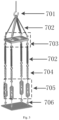
Fig. 1 is a schematic view of the present disclosure; -
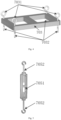
Fig. 2 is a schematic view of an inertia simulation tooling and a disturbance source in the present disclosure; -
Fig. 3 is a schematic view of a variable-stroke self-adaptive adjustment quasi-zero stiffness device in the present disclosure; -
Fig. 4 is a schematic view of a-shaped tooling and a suspension point in the present disclosure; -
Fig. 5 is a schematic view of a double-stroke bolt assembly in the present disclosure; -
Fig. 6 is a schematic view of a parameter definition of a two-pendulum system in the present disclosure; and -
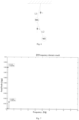
Fig. 7 is a schematic view of a theoretical solution value of a stiffness of a two-pendulum system in the present disclosure. - The present disclosure provides a variable-stroke self-adaptive adjustment quasi-zero stiffness device and a parameter checking method of the same. The device is configured as a two-pendulum system, and a quasi-zero stiffness condition of an on-orbit free boundary condition is simulated in a ground laboratory environment through the variable-stroke self-adaptive adjustment quasi-zero stiffness device. Through the design of a variable-stroke and double-stroke adjustment bolt, the adjustment of pitch and yaw attitudes is creatively realized when the pointing measuring instrument is suspended, so that the target is aligned in the focal plane of the pointing measuring instrument. At the same time, the key parameters of the zero stiffness device are effectively checked to ensure that the design of the zero stiffness device meets the requirements and the indexes are reliable. The present disclosure can comprehensively evaluate and quantitatively analyze the influence of the platform micro-vibration environment on the spatial pointing measuring instrument with the extremely high precision.
- The present disclosure will be described in detail below with reference to
Figs. 1 to 3 and specific embodiments. - As shown in
Fig. 1 , a variable-stroke self-adaptive adjustment quasi-zero stiffness device proposed by the present disclosure includes: an integratingsphere 10, atarget 20, acollimator 30, apointing measuring instrument 40, adisturbance source 50, aninertia simulation tooling 60, a quasi-zero stiffnesssuspension adjustment device 70 and an optical air-bearingplatform 80. - The integrating
sphere 10, thetarget 20 and thecollimator 30 are coaxially mounted on the optical air-bearingplatform 80 in sequence. The integratingsphere 10 provides a light source, thetarget 20 provides point target information, and thecollimator 30 simulates infinity. Thepointing measuring instrument 40 is an object to be tested, theinertia simulation tooling 60 has a hollow cubic structure, and thepointing measuring instrument 40 is connected and fixed with theinertia simulation tooling 60 through a screw. Threedisturbance sources 50 are mounted on theinertia simulation tooling 60 to provide small disturbance and inertia for thepointing measuring instrument 40. The quasi-zero stiffnesssuspension adjustment device 70 suspends theinertia simulation tooling 60 to provide a free boundary environment. The quasi-zero stiffnesssuspension adjustment device 70, thepointing measuring instrument 40, thedisturbance source 50 and theinertia simulation tooling 60 form a set of two-pendulum system as a whole. The basic characteristic frequencies of the two-pendulum system in the present disclosure are 0.114Hz and 0.295Hz, respectively. - As shown in
Fig. 2 , theinertia simulation tooling 60 is provided with a mountingflange 604, and is connected with thepointing measuring instrument 40 through the mountingflange 604, and acounterweight 603 is mounted on a side surface of theinertia simulation tooling 60 opposite to thepointing measuring instrument 40. The threedisturbance sources 50 are respectively mounted on three surfaces of theinertia simulation tooling 60, and the normals of the threedisturbance sources 50 are perpendicular to each other. - After the
inertia simulation tooling 60 is suspended, the direction adjustment of six degrees of freedom of x, y, z, U, V and W is carried out by the quasi-zero stiffnesssuspension adjustment device 70, so that thepointing measuring instrument 40 faces thecollimator 30, where x, y and z are defined to represent three mutually perpendicular coordinate axis directions with a center of mass of the pointing measuring instrument as an origin, z is an optical axis direction, and U, V and W respectively represent directions of degrees of freedom for rotation around the x, y and z axes. - As shown in
Fig. 3 andFig. 4 , the quasi-zero stiffnesssuspension adjustment device 70 includes asuspension crown block 701, high-stiffness suspenders 702, a-shapedtooling 703, a high-modulus and high-stiffness spring 704, a double-stroke bolt assembly 705 and afirst suspension point 706. - The-shaped
tooling 703 is arranged horizontally, with four second suspension points 7031 at four corners of its upper end face and fourthird suspension points 7032 at four corners of its lower end face. The four second suspension points 7031 are respectively connected to thesuspension crown block 701 through the high-stiffness suspenders 702, and the fourthird suspension points 7032 are respectively connected to upper ends of corresponding high-modulus and high-stiffness springs 704 under the-shapedtooling 703 through the high-stiffness suspenders 702. Lower ends of the four high-modulus and high-stiffness springs 704 are respectively connected to the first suspension points 706 through the double-stroke bolt assemblies 705. - The top of the
inertia simulation tooling 60 is provided with fourhooks 601, which are respectively connected with four first suspension points 706 at a lower end of the quasi-zero stiffnesssuspension adjustment device 70. The double-stroke bolt assembly 705 includes a two-sided nut frame 7051 and two M16 high-strength bolts 7052, as shown inFig. 5 . - The rated load of the
suspension crown block 701 is not less than 5 tons, and the effective length of the wire rope of the crown block is not less than 30 meters. The rated load of the high-stiffness suspender 702 is 300 kilograms, and the effective length of the high-stiffness suspender 702 is 3 meters. The rated loads ofsuspension points -shapedtooling 703 are 300 kilograms. The shear modulus of the high-modulus and high-stiffness spring 704 is not less than 78500 N/mm2, and the ultimate tensile strength of the high-modulus and high-stiffness spring 704 is not less than 1500 MPa. The pitch of the threads of the double-stroke bolt assembly is 1 mm, that is, when the two-sided nut frame rotates by one circle, the stroke in the normal direction of the bolt diameter changes by 2 mm. The integratingsphere 10, thetarget 20 and thecollimator 30 are coaxially mounted on the optical air-bearingplatform 80 in sequence, so as to constitute the basic physical environment of the device. The integratingsphere 10 provides a light source, thetarget 20 provides the point target information, and thecollimator 30 simulates the infinity. Thepointing measuring instrument 40 is the object to be tested, theinertia simulation tooling 60 has the hollow cubic structure, and thepointing measuring instrument 40 is connected and fixed with theinertia simulation tooling 60 through the screw. Threedisturbance sources 50 are mounted on theinertia simulation tooling 60 to provide the small disturbance and inertia for thepointing measuring instrument 40. The quasi-zero stiffnesssuspension adjustment device 70 suspends theinertia simulation tooling 60 to provide the free boundary environment. The quasi-zero stiffnesssuspension adjustment device 70, thepointing measuring instrument 40, thedisturbance source 50 and theinertia simulation tooling 60 form a set of two-pendulum system as a whole, and the basic characteristic frequencies of the two-pendulum system are 0.114 Hz and 0.295 Hz, respectively. The direction adjustment of six degrees of freedom of thepointing measuring instrument 40 is realized by the quasi-zero stiffnesssuspension adjustment device 70, so that the center of thepointing measuring instrument 40 is aligned with the axis of thecollimator 30. - The parameters of the high-modulus and high-
stiffness spring 704 are as follows.Name of physical quantity Value Inner Diameter D1 ϕ35mm Middle Diameter D2 cp40mm Outer Diameter D ϕ45mm Wire Diameter d ϕ5mm Total Number of Turns N 80 Pitch p 5mm Free Height H0 400mm Shear Modulus of Carbon Spring Steel G 78500N/mm2 Ultimate Tensile Strength of Carbon ≥1320MPa Spring Steel Wire σb - The parameter checking is divided into quasi-zero stiffness checking and strength checking. The quasi-zero stiffness checking is to confirm that the designed device meets the quasi-zero stiffness condition and can meet the test requirements. The strength checking is to ensure the safety and reliability of the system, and avoid damages and potential safety hazards.
- In the quasi-zero stiffness checking, a variable-stroke self-adaptive adjustment quasi-zero stiffness device is configured as a two-pendulum system, a dynamic equation of the two-pendulum system is established by the Lagrangue equation method, and the equation is a second-order implicit differential equation set in two variables, and is solved by the Runge-Kutta numerical solution method to obtain the characteristic frequency of the device, that is, the stiffness value of the variable-stroke self-adaptive adjustment quasi-zero stiffness device.
- The strength checking in the present disclosure mainly lies in the strength checking of the high-modulus and high-stiffness spring to ensure safety, and the strength checking mainly uses the strength checking calculation formula of the spring to check the shear stress of the spring wire.
- In the adjustment resolution calculation, the adjustment of the pointing measuring instrument in the U and V directions and the position adjustment of the target on the focal plane of the pointing measuring instrument are realized through the double-stroke bolt assembly.
- Specifically, the parameter checking in the present disclosure includes three steps.
- As shown in
Fig. 6 , in the present disclosure, the quasi-zero stiffnesssuspension adjustment device 70, thepointing measuring instrument 40, thedisturbance source 50 and theinertia simulation tooling 60 are integrated into a set of two-pendulum system. If the quasi-zero stiffnesssuspension adjustment device 70 is regarded as a concentrated mass M1, and thepointing measuring instrument 40, thedisturbance source 50 and theinertia simulation tooling 60 are regarded as another object M2, they form a two-pendulum system. - The Lagrangue equation method is used to establish the dynamic equation of the two-pendulum system, and the equation is a second-order implicit differential equation set in two variables, and is solved by the Runge-Kutta numerical solution method to obtain the characteristic frequency of the device, that is, the stiffness value of the variable-stroke self-adaptive adjustment quasi-zero stiffness device.
- The dynamic equation of the two-pendulum system can be obtained by the Lagrangue equation method, as follows:

- L1 is a length of a first swing arm of the two-pendulum system, L2 is a length of a second swing arm of the two-pendulum system, m1 is an equivalent mass point of the first swing arm of the two-pendulum system, m2 is an equivalent mass point of the second swing arm of the two-pendulum system, g is the gravitational acceleration, θ1 is an included angle between the first swing arm and the gravitational acceleration g, and θ2 is an included angle between the second swing arm and the gravitational acceleration g. Two dots on θ1 and θ2 represent a second derivative.
- The ode15i function in Matlab is used to solve the equation, and the result is subjected to a FFT analysis. The characteristic frequencies caused by the two-pendulum system are 0.114 Hz and 0.295 Hz respectively, which are very close to zero stiffness and meet the quasi-zero stiffness condition, as shown in
Fig. 7 . - At the same time, the quasi-zero stiffness frequency is further checked by using the finite element analysis method, and the transverse characteristic frequencies are 0.13 Hz and 0.27 Hz respectively, which are consistent with the theoretical calculation results, thus proving the quasi-zero stiffness characteristics in the present disclosure again.
- The strength checking in the present disclosure mainly lies in the strength checking of the high-modulus and high-stiffness spring to ensure safety, and the strength checking mainly uses the strength checking calculation formula of the spring to check the shear stress of the spring wire.
- Common parameters of a cylindrical helical tension spring mainly include:
- winding ratio:

- effective laps:

- compensation coefficient:

- stiffness coefficient:

- allowable shear stress:

- For the tension spring, the strength checking mainly checks the shear stress of the spring wire, and the calculation formula for the strength checking of the spring is:

- It is assumed that the maximum load of each spring is one quarter of the whole machine mass, and the whole machine mass is not more than 110kg.
- Each parameter is brought into the equation, and the calculation result is:

- The adjustment of the pointing measuring instrument in the U and V directions and the position adjustment of the target in the focal plane of the pointing measuring instrument are realized by the double-stroke bolt assembly.
- The adjustment resolution is denoted as:

- Zu represents the pitch, L` represents an effective length of the pointing measuring instrument of the two-pendulum system in the optical axis direction, and the adjustment resolution Θu should not be greater than 0.5'.
- The target is adjusted to be within the field of view of the pointing measuring instrument through the double-stroke bolt assembly.
- The M16 high-strength bolt is used as the double-stroke bolt, and its pitch is 1mm, that is, when the two-sided nut frame rotates by one circle, a change value at either end of the bolt is 2mm. Based on this, the adjustment resolution of a single turn is calculated as follows:


- That is to say, the two-sided nut frame can move 2mm in the Z direction when rotating by one circle, and a corresponding angle is 0.23°. The resolution during actual operation and adjustment is far better than the above index. If a scale of a single turn is divided into 60 parts, then:


- During the test, the target can be adjusted to be within the field of view of the pointing measuring instrument in a short time through the double-stroke bolt assembly.
- The specific object involved in the present disclosure, i.e. the spatial pointing measuring instrument, may also be specifically space optical instruments, photoelectric instruments, and high-precision pointing measuring instruments, such as high-resolution space cameras and sky survey telescopes, which need to be subjected to the quasi-zero stiffness environment to simulate the micro-vibration test of the space instruments with free boundaries.
- Parts of the present disclosure that are not described in detail belong to the common sense of those skill in the art.
Claims (11)
- A variable-stroke self-adaptive adjustment quasi-zero stiffness device, comprising an integrating sphere (10), a target (20), a collimator (30), a pointing measuring instrument (40), a disturbance source (50), an inertia simulation tooling (60), a quasi-zero stiffness suspension adjustment device (70) and an optical air-bearing platform (80),
wherein the integrating sphere (10), the target (20) and the collimator (30) are coaxially mounted on the optical air-bearing platform (80) in sequence; the integrating sphere (10) provides a light source, the target (20) provides point target information, and the collimator (30) simulates infinity; the pointing measuring instrument (40) is an object to be tested, the inertia simulation tooling (60) is a hollow cubic structure, and the pointing measuring instrument (40) is connected and fixed with the inertia simulation tooling (60) through a screw; three disturbance sources (50) are mounted on the inertia simulation tooling (60) to provide small disturbance and inertia for the pointing measuring instrument (40); the quasi-zero stiffness suspension adjustment device (70) suspends the inertia simulation tooling (60) to provide a free boundary environment; and the quasi-zero stiffness suspension adjustment device (70), the pointing measuring instrument (40), the disturbance source (50) and the inertia simulation tooling (60) form a set of two-pendulum system as a whole. - The variable-stroke self-adaptive adjustment quasi-zero stiffness device according to claim 1, wherein the inertia simulation tooling (60) comprises a mounting flange (604), and is connected with the pointing measuring instrument (40) through the mounting flange (604), and a counterweight (603) is mounted on a side surface of the inertia simulation tooling (60) opposite to the pointing measuring instrument (40).
- The variable-stroke self-adaptive adjustment quasi-zero stiffness device according to claim 1, wherein after the inertia simulation tooling (60) is suspended, the quasi-zero stiffness suspension adjustment device (70) preforms a direction adjustment of six degrees of freedom (x, y, z, U, V, W) such that the pointing measuring instrument (40) faces the collimator (30), wherein x, y and z are defined to represent three mutually perpendicular coordinate axis directions with a center of mass of the pointing measuring instrument as an origin, z is an optical axis direction, and U,V and W represent directions of degrees of freedom for rotation around the x, y and z axes, respectively.
- The variable-stroke self-adaptive adjustment quasi-zero stiffness device according to claim 1, wherein basic characteristic frequencies of the two-pendulum system are 0.114 Hz and 0.295 Hz, respectively.
- The variable-stroke self-adaptive adjustment quasi-zero stiffness device according to claim 1, wherein three disturbance sources (50) are mounted on three surfaces of the inertia simulation tooling (60), respectively, and normals of the three disturbance sources (50) are perpendicular to each other.
- The variable-stroke self-adaptive adjustment quasi-zero stiffness device according to claim 1, wherein the quasi-zero stiffness suspension adjustment device (70) comprises: a suspension crown block (701), high-stiffness suspenders (702), a-shaped tooling (703), a high-modulus and high-stiffness spring (704), a double-stroke bolt assembly (705) and a first suspension point (706);

wherein the-shaped tooling (703) is arranged horizontally, with four second suspension points (7031) at four corners of its upper end face and four third suspension points (7032) at four corners of its lower end face; the four second suspension points (7031) are respectively connected to the suspension crown block (701) through the high-stiffness suspenders (702), and the four third suspension points (7032) are respectively connected to upper ends of corresponding high-modulus and high-stiffness springs (704) under the-shaped tooling (703) through the high-stiffness suspenders (702); and lower ends of four high-modulus and high-stiffness springs (704) each are connected with the first suspension point (706) through the double-stroke bolt assembly (705). - The variable-stroke self-adaptive adjustment quasi-zero stiffness device according to claim 6, wherein a top of the inertia simulation tooling (60) comprises four hooks (601), which are respectively connected with four first suspension points (706) at a lower end of the quasi-zero stiffness suspension adjustment device (70); and the double-stroke bolt assembly (705) comprises a two-sided nut frame (7051) and two M16 high-strength bolts (7052).
- A parameter checking method of a variable-stroke self-adaptive adjustment quasi-zero stiffness device according to claim 1, comprising:step 1, checking a quasi-zero stiffness frequency, wherein according to the two-pendulum system formed by the quasi-zero stiffness suspension adjustment device, the pointing measuring instrument, the disturbance source and the inertia simulation tooling as a whole, a dynamic equation of the two-pendulum system is established and solved to obtain a characteristic frequency of the variable-stroke self-adaptive adjustment quasi-zero stiffness device, i.e. a stiffness value of the variable-stroke self-adaptive adjustment quasi-zero stiffness device;step 2, checking a strength, wherein a shear stress of a spring wire is checked by a strength checking calculation formula of the high-modulus and high-stiffness spring; andstep 3, checking an adjustment resolution, wherein an adjustment of the pointing measuring instrument in the U and V directions and a position adjustment of the target on a focal plane of the pointing measuring instrument are realized through the double-stroke bolt assembly.
- The parameter checking method of the variable-stroke self-adaptive adjustment quasi-zero stiffness device according to claim 8, wherein the dynamic equation of the two-pendulum system is established by a Lagrangue equation method, and the equation is a second-order implicit differential equation set in two variables, and is solved by a Runge-Kutta numerical solution method to obtain the characteristic frequency of the device, i.e., the stiffness value of the variable-stroke self-adaptive adjustment quasi-zero stiffness device,specifically, the dynamic equation of the two-pendulum system is established by the Lagrangue equation method as follows:
 wherein, L1 is a length of a first swing arm of the two-pendulum system, L2 is a length of a second swing arm of the two-pendulum system, m1 is an equivalent mass point of the first swing arm of the two-pendulum system, m2 is an equivalent mass point of the second swing arm of the two-pendulum system, g is a gravitational acceleration, θ1 is an included angle between the first swing arm and the gravitational acceleration g, and θ2 is an included angle between the second swing arm and the gravitational acceleration g; and two dots on θ1 and θ2 represent a second derivative;an ode15i function in Matlabr is used to solve the equation, and a result is subjected to a FFT analysis to determine whether the characteristic frequency caused by the two-pendulum system is close to zero stiffness and meets a quasi-zero stiffness condition; anda finite element analysis method is used to further check the quasi-zero stiffness frequency to determine whether its transverse characteristic frequency is consistent with a theoretical calculation result.
 - The parameter checking method of the variable-stroke self-adaptive adjustment quasi-zero stiffness device according to claim 8, wherein checking the strength specifically comprises:
the strength checking calculation formula of the spring being:
- The parameter checking method of the variable-stroke self-adaptive adjustment quasi-zero stiffness device according to claim 8, wherein checking the adjustment resolution specifically comprises:calculating the adjustment resolution, wherein the adjustment of the pointing measuring instrument in the U and V directions and the position adjustment of the target on the focal plane of the pointing measuring instrument are realized through the double-stroke bolt assembly;wherein the adjustment resolution is denoted as:
 wherein Zu represents a pitch, L` represents an effective length of the pointing measuring instrument of the two-pendulum system in the optical axis direction, and the adjustment resolution Θu should not be greater than 0.5'; andwherein the target is adjusted to be within a field of view of the pointing measuring instrument through the double-stroke bolt assembly.
Applications Claiming Priority (2)
| Application Number | Priority Date | Filing Date | Title |
|---|---|---|---|
| CN202110978217.XA CN113919190B (en) | 2021-08-23 | 2021-08-23 | A quasi-zero stiffness device and parameter checking method for variable stroke adaptive adjustment |
| PCT/CN2022/112709 WO2023024968A1 (en) | 2021-08-23 | 2022-08-16 | Variable-stroke self-adaptive adjustment quasi-zero stiffness device and parameter checking method |
Publications (2)
| Publication Number | Publication Date |
|---|---|
| EP4394643A1 true EP4394643A1 (en) | 2024-07-03 |
| EP4394643A4 EP4394643A4 (en) | 2025-08-20 |
Family
ID=79233160
Family Applications (1)
| Application Number | Title | Priority Date | Filing Date |
|---|---|---|---|
| EP22860314.8A Pending EP4394643A4 (en) | 2021-08-23 | 2022-08-16 | Self-adjusting device with variable stroke adjustment for quasi-zero stiffness and parameter testing method |
Country Status (4)
| Country | Link |
|---|---|
| US (1) | US20240367823A1 (en) |
| EP (1) | EP4394643A4 (en) |
| CN (1) | CN113919190B (en) |
| WO (1) | WO2023024968A1 (en) |
Families Citing this family (8)
| Publication number | Priority date | Publication date | Assignee | Title |
|---|---|---|---|---|
| CN113919190B (en) * | 2021-08-23 | 2022-06-03 | 北京控制工程研究所 | A quasi-zero stiffness device and parameter checking method for variable stroke adaptive adjustment |
| CN114988280B (en) * | 2022-06-02 | 2023-03-17 | 长光卫星技术股份有限公司 | Satellite ground test flexible support zero-stress suspension device and suspension method |
| CN116698369A (en) * | 2023-05-29 | 2023-09-05 | 中国科学院长春光学精密机械与物理研究所 | Multispectral dynamic optical equipment imaging quality degradation evaluation device |
| CN117284506B (en) * | 2023-08-09 | 2024-03-08 | 南京航空航天大学 | Microgravity impact dynamics test platform and test method for aerospace adsorption mechanism |
| CN117944095B (en) * | 2024-03-25 | 2024-08-16 | 中国科学院长春光学精密机械与物理研究所 | Variable torque controllable time-varying stiffness flexible base |
| CN119394562B (en) * | 2024-12-31 | 2025-03-25 | 石家庄铁道大学 | Frequency Modulation Method of Free Vibration Test System |
| CN119808598B (en) * | 2025-03-11 | 2025-06-06 | 中南大学 | Multistage quasi-zero stiffness super-structure design method based on reinforcement learning |
| CN120971074B (en) * | 2025-10-23 | 2026-01-06 | 华中科技大学 | A six-degree-of-freedom ground-based testing apparatus and method for verifying mass release processes. |
Family Cites Families (19)
| Publication number | Priority date | Publication date | Assignee | Title |
|---|---|---|---|---|
| CN101839731B (en) * | 2010-05-18 | 2012-05-23 | 浙江工业大学 | Undisturbed air-flotation magnetomotive suspension device based on double electromagnetic forces |
| CN102650563B (en) * | 2011-12-20 | 2015-04-08 | 北京卫星环境工程研究所 | Ground testing system for on-track micro vibration of spacecraft |
| CN103279595B (en) * | 2013-04-27 | 2016-04-27 | 上海卫星工程研究所 | The non-linear suspension system method for designing of accurate zero stiffness |
| CN103482088B (en) | 2013-08-12 | 2015-07-15 | 上海卫星工程研究所 | Satellite micro-vibration test multi-point suspension system and design method thereof |
| US9920793B1 (en) * | 2013-12-06 | 2018-03-20 | Hrl Laboratories, Llc | Negative stiffness system with variable preload adjustment |
| CN104386267B (en) * | 2014-11-03 | 2016-07-06 | 哈尔滨工业大学 | Control experiment device and method is pointed to suitable in spacecraft high stability |
| CN105253333A (en) * | 2015-11-23 | 2016-01-20 | 上海卫星装备研究所 | Low-rigidity flexible suspension device for ground gravity-free condition simulation of aerospace products |
| CN105530514A (en) * | 2016-01-28 | 2016-04-27 | 长光卫星技术有限公司 | Testing device for affect of satellite platform micro-vibration on camera imaging |
| CN106477074B (en) * | 2016-11-29 | 2019-07-12 | 上海卫星装备研究所 | A kind of in-orbit super quiet weightlessness simulation experiment system of novel spacecraft |
| CN106599480A (en) * | 2016-12-16 | 2017-04-26 | 中国科学院长春光学精密机械与物理研究所 | Modification method of space camera on-orbit micro-vibration simulation model |
| CN107941441B (en) * | 2017-11-14 | 2019-12-03 | 北京卫星环境工程研究所 | Determine the method that in-orbit boundary influences the in-orbit kinetic characteristics of spacecraft of simulating |
| CN108801574B (en) * | 2018-06-15 | 2020-06-05 | 北京卫星环境工程研究所 | Verification system for optical axis jitter performance of spacecraft high-resolution camera |
| CN109540493B (en) * | 2018-12-21 | 2019-10-25 | 东北大学 | A test device for a quasi-zero stiffness vibration isolator |
| CN110929388A (en) * | 2019-11-06 | 2020-03-27 | 中国科学院微小卫星创新研究院 | Aircraft vibration interference analysis method based on fine tracking camera |
| CN111207895B (en) * | 2020-01-13 | 2022-01-07 | 中国科学院微小卫星创新研究院 | Ground micro-vibration experiment system and method for remote sensing micro-nano satellite |
| CN111157208A (en) * | 2020-02-27 | 2020-05-15 | 广州大学 | Satellite micro-vibration isolation simulation measurement system and method |
| CN111638721B (en) * | 2020-04-28 | 2023-08-11 | 北京控制工程研究所 | A verification system and verification method for full-link disturbance transfer of spacecraft three-super-control |
| CN112504595B (en) * | 2020-10-27 | 2022-07-05 | 北京控制工程研究所 | Device and method for measuring the influence of micro-vibration on a spatial pointing measuring instrument |
| CN113919190B (en) * | 2021-08-23 | 2022-06-03 | 北京控制工程研究所 | A quasi-zero stiffness device and parameter checking method for variable stroke adaptive adjustment |
-
2021
- 2021-08-23 CN CN202110978217.XA patent/CN113919190B/en active Active
-
2022
- 2022-08-16 EP EP22860314.8A patent/EP4394643A4/en active Pending
- 2022-08-16 WO PCT/CN2022/112709 patent/WO2023024968A1/en not_active Ceased
- 2022-08-16 US US18/685,965 patent/US20240367823A1/en active Pending
Also Published As
| Publication number | Publication date |
|---|---|
| WO2023024968A1 (en) | 2023-03-02 |
| EP4394643A4 (en) | 2025-08-20 |
| CN113919190A (en) | 2022-01-11 |
| US20240367823A1 (en) | 2024-11-07 |
| CN113919190B (en) | 2022-06-03 |
Similar Documents
| Publication | Publication Date | Title |
|---|---|---|
| EP4394643A1 (en) | Variable-stroke self-adaptive adjustment quasi-zero stiffness device and parameter checking method | |
| US12085474B2 (en) | Apparatus and method for measuring micro-vibration influence of spatial orientation measuring instrument | |
| CN108760150B (en) | Large-scale force value symmetrical loading force and moment decoupling calibration device | |
| CN109141905B (en) | Six-component force test bed and method for measuring vector thrust thereof | |
| EP2613134B1 (en) | System and method for aligning a test article with a load | |
| CN104344804B (en) | Satellite simulation zero gravity state single machine pointing accuracy measurement method | |
| CN101226094A (en) | A calibration method for a six-dimensional force sensor calibration device | |
| CN107238457A (en) | A kind of low thrust measurement apparatus | |
| US2782636A (en) | Internal balances for wind force measurements on aerodynamic objects | |
| CN109115510B (en) | Six-component force test bed and error determination method thereof | |
| CN103616116A (en) | Mechanical decoupling heavy load parallel six-dimension force measuring platform | |
| CN113029415A (en) | Non-interference multi-component solid rocket engine thrust measurement system and installation measurement method | |
| Runyan et al. | Thrust stand design principles | |
| CN107702835A (en) | Restructural parallel connection three-dimensional force/torque sensor | |
| Coppa et al. | Dynamic buckling of shell structures subject to longitudinal impact | |
| CN219302146U (en) | Rail control rack static test device for spacecraft | |
| CN114739833B (en) | Three-way adjustable test loading system | |
| Chai et al. | Development of a multi-component force measurement platform for vector thrust calibration of aviation engines | |
| Trim et al. | Improved Ribbon Bridge structural response validation testing | |
| Hudson et al. | Development of a differential accelerometer to test the equivalence principle in the microscope mission | |
| CN211504588U (en) | Be used for nuclear power station reactor body shock resistance test structure | |
| Bennett et al. | Improved Ribbon Bridge structural response validation testing | |
| US20260092836A1 (en) | Platform balance with a tare assembly having a compression strut | |
| Ni et al. | Research on in-situ calibration technology of multidimensional force for space docking mechanism buffering test-bed | |
| Vann et al. | An Improved High-Capacity Balance Calibration Methodology |
Legal Events
| Date | Code | Title | Description |
|---|---|---|---|
| STAA | Information on the status of an ep patent application or granted ep patent |
Free format text: STATUS: THE INTERNATIONAL PUBLICATION HAS BEEN MADE |
|
| PUAI | Public reference made under article 153(3) epc to a published international application that has entered the european phase |
Free format text: ORIGINAL CODE: 0009012 |
|
| STAA | Information on the status of an ep patent application or granted ep patent |
Free format text: STATUS: REQUEST FOR EXAMINATION WAS MADE |
|
| 17P | Request for examination filed |
Effective date: 20240308 |
|
| AK | Designated contracting states |
Kind code of ref document: A1 Designated state(s): AL AT BE BG CH CY CZ DE DK EE ES FI FR GB GR HR HU IE IS IT LI LT LU LV MC MK MT NL NO PL PT RO RS SE SI SK SM TR |
|
| DAV | Request for validation of the european patent (deleted) | ||
| DAX | Request for extension of the european patent (deleted) | ||
| A4 | Supplementary search report drawn up and despatched |
Effective date: 20250718 |
|
| RIC1 | Information provided on ipc code assigned before grant |
Ipc: G06F 30/23 20200101AFI20250714BHEP Ipc: G01M 13/00 20190101ALI20250714BHEP Ipc: B64G 7/00 20060101ALI20250714BHEP Ipc: F16D 7/00 20060101ALI20250714BHEP Ipc: G01M 11/04 20060101ALI20250714BHEP Ipc: G06F 30/20 20200101ALI20250714BHEP Ipc: G06F 119/14 20200101ALI20250714BHEP |
|
| GRAP | Despatch of communication of intention to grant a patent |
Free format text: ORIGINAL CODE: EPIDOSNIGR1 |
|
| STAA | Information on the status of an ep patent application or granted ep patent |
Free format text: STATUS: GRANT OF PATENT IS INTENDED |