EP4394549A2 - Faltbare anzeigevorrichtung - Google Patents
Faltbare anzeigevorrichtung Download PDFInfo
- Publication number
- EP4394549A2 EP4394549A2 EP23218541.3A EP23218541A EP4394549A2 EP 4394549 A2 EP4394549 A2 EP 4394549A2 EP 23218541 A EP23218541 A EP 23218541A EP 4394549 A2 EP4394549 A2 EP 4394549A2
- Authority
- EP
- European Patent Office
- Prior art keywords
- display apparatus
- folding
- disposed
- heat dissipation
- foldable display
- Prior art date
- Legal status (The legal status is an assumption and is not a legal conclusion. Google has not performed a legal analysis and makes no representation as to the accuracy of the status listed.)
- Pending
Links
Images












Classifications
-
- G—PHYSICS
- G06—COMPUTING OR CALCULATING; COUNTING
- G06F—ELECTRIC DIGITAL DATA PROCESSING
- G06F1/00—Details not covered by groups G06F3/00 - G06F13/00 and G06F21/00
- G06F1/16—Constructional details or arrangements
- G06F1/20—Cooling means
- G06F1/203—Cooling means for portable computers, e.g. for laptops
-
- G—PHYSICS
- G06—COMPUTING OR CALCULATING; COUNTING
- G06F—ELECTRIC DIGITAL DATA PROCESSING
- G06F1/00—Details not covered by groups G06F3/00 - G06F13/00 and G06F21/00
- G06F1/16—Constructional details or arrangements
- G06F1/1613—Constructional details or arrangements for portable computers
- G06F1/1633—Constructional details or arrangements of portable computers not specific to the type of enclosures covered by groups G06F1/1615 - G06F1/1626
- G06F1/1637—Details related to the display arrangement, including those related to the mounting of the display in the housing
- G06F1/1641—Details related to the display arrangement, including those related to the mounting of the display in the housing the display being formed by a plurality of foldable display components
-
- G—PHYSICS
- G09—EDUCATION; CRYPTOGRAPHY; DISPLAY; ADVERTISING; SEALS
- G09F—DISPLAYING; ADVERTISING; SIGNS; LABELS OR NAME-PLATES; SEALS
- G09F9/00—Indicating arrangements for variable information in which the information is built-up on a support by selection or combination of individual elements
- G09F9/30—Indicating arrangements for variable information in which the information is built-up on a support by selection or combination of individual elements in which the desired character or characters are formed by combining individual elements
- G09F9/301—Indicating arrangements for variable information in which the information is built-up on a support by selection or combination of individual elements in which the desired character or characters are formed by combining individual elements flexible foldable or roll-able electronic displays, e.g. thin LCD, OLED
-
- F—MECHANICAL ENGINEERING; LIGHTING; HEATING; WEAPONS; BLASTING
- F16—ENGINEERING ELEMENTS AND UNITS; GENERAL MEASURES FOR PRODUCING AND MAINTAINING EFFECTIVE FUNCTIONING OF MACHINES OR INSTALLATIONS; THERMAL INSULATION IN GENERAL
- F16C—SHAFTS; FLEXIBLE SHAFTS; ELEMENTS OR CRANKSHAFT MECHANISMS; ROTARY BODIES OTHER THAN GEARING ELEMENTS; BEARINGS
- F16C11/00—Pivots; Pivotal connections
- F16C11/04—Pivotal connections
-
- F—MECHANICAL ENGINEERING; LIGHTING; HEATING; WEAPONS; BLASTING
- F16—ENGINEERING ELEMENTS AND UNITS; GENERAL MEASURES FOR PRODUCING AND MAINTAINING EFFECTIVE FUNCTIONING OF MACHINES OR INSTALLATIONS; THERMAL INSULATION IN GENERAL
- F16C—SHAFTS; FLEXIBLE SHAFTS; ELEMENTS OR CRANKSHAFT MECHANISMS; ROTARY BODIES OTHER THAN GEARING ELEMENTS; BEARINGS
- F16C11/00—Pivots; Pivotal connections
- F16C11/04—Pivotal connections
- F16C11/045—Pivotal connections with at least a pair of arms pivoting relatively to at least one other arm, all arms being mounted on one pin
-
- F—MECHANICAL ENGINEERING; LIGHTING; HEATING; WEAPONS; BLASTING
- F16—ENGINEERING ELEMENTS AND UNITS; GENERAL MEASURES FOR PRODUCING AND MAINTAINING EFFECTIVE FUNCTIONING OF MACHINES OR INSTALLATIONS; THERMAL INSULATION IN GENERAL
- F16C—SHAFTS; FLEXIBLE SHAFTS; ELEMENTS OR CRANKSHAFT MECHANISMS; ROTARY BODIES OTHER THAN GEARING ELEMENTS; BEARINGS
- F16C11/00—Pivots; Pivotal connections
- F16C11/04—Pivotal connections
- F16C11/12—Pivotal connections incorporating flexible connections, e.g. leaf springs
-
- G—PHYSICS
- G06—COMPUTING OR CALCULATING; COUNTING
- G06F—ELECTRIC DIGITAL DATA PROCESSING
- G06F1/00—Details not covered by groups G06F3/00 - G06F13/00 and G06F21/00
- G06F1/16—Constructional details or arrangements
- G06F1/1613—Constructional details or arrangements for portable computers
- G06F1/1615—Constructional details or arrangements for portable computers with several enclosures having relative motions, each enclosure supporting at least one I/O or computing function
- G06F1/1616—Constructional details or arrangements for portable computers with several enclosures having relative motions, each enclosure supporting at least one I/O or computing function with folding flat displays, e.g. laptop computers or notebooks having a clamshell configuration, with body parts pivoting to an open position around an axis parallel to the plane they define in closed position
- G06F1/1618—Constructional details or arrangements for portable computers with several enclosures having relative motions, each enclosure supporting at least one I/O or computing function with folding flat displays, e.g. laptop computers or notebooks having a clamshell configuration, with body parts pivoting to an open position around an axis parallel to the plane they define in closed position the display being foldable up to the back of the other housing with a single degree of freedom, e.g. by 360° rotation over the axis defined by the rear edge of the base enclosure
-
- G—PHYSICS
- G06—COMPUTING OR CALCULATING; COUNTING
- G06F—ELECTRIC DIGITAL DATA PROCESSING
- G06F1/00—Details not covered by groups G06F3/00 - G06F13/00 and G06F21/00
- G06F1/16—Constructional details or arrangements
- G06F1/1613—Constructional details or arrangements for portable computers
- G06F1/1633—Constructional details or arrangements of portable computers not specific to the type of enclosures covered by groups G06F1/1615 - G06F1/1626
- G06F1/1637—Details related to the display arrangement, including those related to the mounting of the display in the housing
-
- G—PHYSICS
- G06—COMPUTING OR CALCULATING; COUNTING
- G06F—ELECTRIC DIGITAL DATA PROCESSING
- G06F1/00—Details not covered by groups G06F3/00 - G06F13/00 and G06F21/00
- G06F1/16—Constructional details or arrangements
- G06F1/1613—Constructional details or arrangements for portable computers
- G06F1/1633—Constructional details or arrangements of portable computers not specific to the type of enclosures covered by groups G06F1/1615 - G06F1/1626
- G06F1/1637—Details related to the display arrangement, including those related to the mounting of the display in the housing
- G06F1/1652—Details related to the display arrangement, including those related to the mounting of the display in the housing the display being flexible, e.g. mimicking a sheet of paper, or rollable
-
- G—PHYSICS
- G06—COMPUTING OR CALCULATING; COUNTING
- G06F—ELECTRIC DIGITAL DATA PROCESSING
- G06F1/00—Details not covered by groups G06F3/00 - G06F13/00 and G06F21/00
- G06F1/16—Constructional details or arrangements
- G06F1/1613—Constructional details or arrangements for portable computers
- G06F1/1633—Constructional details or arrangements of portable computers not specific to the type of enclosures covered by groups G06F1/1615 - G06F1/1626
- G06F1/1675—Miscellaneous details related to the relative movement between the different enclosures or enclosure parts
- G06F1/1681—Details related solely to hinges
-
- H—ELECTRICITY
- H04—ELECTRIC COMMUNICATION TECHNIQUE
- H04M—TELEPHONIC COMMUNICATION
- H04M1/00—Substation equipment, e.g. for use by subscribers
- H04M1/02—Constructional features of telephone sets
- H04M1/0202—Portable telephone sets, e.g. cordless phones, mobile phones or bar type handsets
- H04M1/0206—Portable telephones comprising a plurality of mechanically joined movable body parts, e.g. hinged housings
- H04M1/0208—Portable telephones comprising a plurality of mechanically joined movable body parts, e.g. hinged housings characterized by the relative motions of the body parts
- H04M1/0214—Foldable telephones, i.e. with body parts pivoting to an open position around an axis parallel to the plane they define in closed position
- H04M1/0216—Foldable in one direction, i.e. using a one degree of freedom hinge
-
- H—ELECTRICITY
- H04—ELECTRIC COMMUNICATION TECHNIQUE
- H04M—TELEPHONIC COMMUNICATION
- H04M1/00—Substation equipment, e.g. for use by subscribers
- H04M1/02—Constructional features of telephone sets
- H04M1/0202—Portable telephone sets, e.g. cordless phones, mobile phones or bar type handsets
- H04M1/0206—Portable telephones comprising a plurality of mechanically joined movable body parts, e.g. hinged housings
- H04M1/0208—Portable telephones comprising a plurality of mechanically joined movable body parts, e.g. hinged housings characterized by the relative motions of the body parts
- H04M1/0214—Foldable telephones, i.e. with body parts pivoting to an open position around an axis parallel to the plane they define in closed position
- H04M1/0216—Foldable in one direction, i.e. using a one degree of freedom hinge
- H04M1/022—The hinge comprising two parallel pivoting axes
-
- H—ELECTRICITY
- H04—ELECTRIC COMMUNICATION TECHNIQUE
- H04M—TELEPHONIC COMMUNICATION
- H04M1/00—Substation equipment, e.g. for use by subscribers
- H04M1/02—Constructional features of telephone sets
- H04M1/0202—Portable telephone sets, e.g. cordless phones, mobile phones or bar type handsets
- H04M1/0206—Portable telephones comprising a plurality of mechanically joined movable body parts, e.g. hinged housings
- H04M1/0208—Portable telephones comprising a plurality of mechanically joined movable body parts, e.g. hinged housings characterized by the relative motions of the body parts
- H04M1/0235—Slidable or telescopic telephones, i.e. with a relative translation movement of the body parts; Telephones using a combination of translation and other relative motions of the body parts
- H04M1/0237—Sliding mechanism with one degree of freedom
-
- H—ELECTRICITY
- H04—ELECTRIC COMMUNICATION TECHNIQUE
- H04M—TELEPHONIC COMMUNICATION
- H04M1/00—Substation equipment, e.g. for use by subscribers
- H04M1/02—Constructional features of telephone sets
- H04M1/0202—Portable telephone sets, e.g. cordless phones, mobile phones or bar type handsets
- H04M1/026—Details of the structure or mounting of specific components
- H04M1/0266—Details of the structure or mounting of specific components for a display module assembly
- H04M1/0268—Details of the structure or mounting of specific components for a display module assembly including a flexible display panel
-
- H—ELECTRICITY
- H05—ELECTRIC TECHNIQUES NOT OTHERWISE PROVIDED FOR
- H05K—PRINTED CIRCUITS; CASINGS OR CONSTRUCTIONAL DETAILS OF ELECTRIC APPARATUS; MANUFACTURE OF ASSEMBLAGES OF ELECTRICAL COMPONENTS
- H05K7/00—Constructional details common to different types of electric apparatus
- H05K7/20—Modifications to facilitate cooling, ventilating, or heating
- H05K7/20954—Modifications to facilitate cooling, ventilating, or heating for display panels
Definitions
- the foldable display apparatus can be folded or unfolded based on a hinge device.
- the foldable display apparatus is applied to a small display apparatus such as a smart phone and is also applied to a medium display apparatus such as a tablet PC or a laptop computer.
- An object of the present disclosure is to provide a foldable display apparatus that is rigid in an in-folding state.
- An object of the present disclosure is to provide a foldable display apparatus capable of blocking heat generated from an integrated circuit from being transferred to a panel.
- FIG. 1 is a view illustrating an unfolding state of a display apparatus 10 according to various embodiments of the present disclosure.
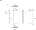
- FIG. 2 is a view illustrating a folding state of the display apparatus 10 according to various embodiments of the present disclosure.
- FIG. 1 the front, upper, lower, right, left, and rear surfaces of the display apparatus 10 in an unfolding state are illustrated.
- FIG. 2 the front, upper, lower, right, left, and rear surfaces of the display apparatus 10 in a folding state are illustrated.
- the side and rear surfaces of the display apparatus 10 may be covered by the cover frame CF.
- the rear surface of the display apparatus 10 is a surface opposite to the front surface, and the side surface refers to a surface between the front and rear surfaces.
- the cover frame CF may include two cover frames CF1 and CF2 physically separated from each other.
- the cover frame CF includes a first cover frame CF1 disposed on one side of the folding axis A1 and a second cover frame CF2 disposed on the other side of the folding axis A1.
- the first cover frame CF1 and the second cover frame CF2 are as illustrated in FIG. 3 .
- the in-folding hinge assembly IHA is disposed close to the rear surface of the display apparatus 10 and is disposed along the folding axis A1.
- the in-folding hinge assembly IHA may be disposed to be covered by the cover frames CF1 and CF2 in an unfolding state. In the unfolding state, the in-folding hinge assembly IHA of the display apparatus 10 may be disposed not to be visible from the outside. Alternatively, in the unfolding state, only a minimum portion of the in-folding hinge assembly IHA of the display apparatus 10 may be visible from the outside.
- the panel PNL is folded so that the first display area DA1 and the second display area DA2 face each other with respect to the folding axis A1.
- the in-folding hinge assembly IHA may be exposed to the outside as the cover frames CF1 and CF2 are rotated and folded.
- the panel PNL is not visible from the outside. Only the cover frames CF and CF2 and in-folding hinge assembly IHA of the display apparatus 10 are visible from the outside.
- the cover frames CF 1 and CF2 are not limited to the shapes and combinations illustrated in FIGS. 1 and 2 , and may be implemented in other shapes or in combination with parts.
- the first cover frame CF1 and the second cover frame CF2 may be disposed on both sides of the folding axis A1 and have a generally symmetrical shape with respect to the folding axis A1.
- the first cover frame CF1 and the second cover frame CF2 may be asymmetrically disposed with respect to the folding axis A1and have an asymmetrical shape.
- the first cover frame CF1 and the second cover frame CF2 may form an inner accommodation space through structural coupling.
- the in-folding hinge assembly IHA and the panel PNL may be accommodated in the inner accommodation space.
- components for driving the display apparatus 10 may be disposed in the inner accommodation space.
- a battery, a control printed circuit board, a flat cable, a flexible printed circuit board, and the like may be disposed in the inner accommodation space.
- the size of the portion exposed to the outside of the in-folding hinge assembly IHA may be different according to the folding angle of the display apparatus 10. For example, in the case where the display apparatus 10 is in a folding state, a large portion of the in-folding hinge assembly IHA may be exposed between the first cover frame CF1 and the second cover frame CF2. In the case where the display apparatus 10 is in an unfolding state, the in-folding hinge assembly IHA may be substantially covered by the first cover frame CF1 and the second cover frame CF2. In the case where the display apparatus 10 is in an intermediate state between the folding state and the unfolding state, a relatively small portion of the in-folding hinge assembly IHA may be exposed between the first cover frame CF1 and the second cover frame CF2.
- an angle formed between the first cover frame CF1 and the second cover frame CF2 may be 180 degrees. Accordingly, an angle formed between the first display area DA1 and the second display area DA2 may be 180 degrees. Thus, the panel PNL may be completely flat.
- the cover frame CF and the top frame TF may be formed of glass or polymer.
- the cover frame CF and the top frame TF may be transparent or opaque.
- the cover frame CF and the top frame TF may be formed of coated or colored glass, ceramic, polymer, aluminum, stainless steel, magnesium, or a combination thereof.
- FIG. 3 is an exploded perspective view of a display apparatus 10 according to various embodiments of the present disclosure.
- a direction along the folding axis A1 in which the display apparatus 10 is folded is defined as an axial direction AD.
- a direction starting from the first display area DA1 and passing through the folding area FA and arriving at the second display area DA2 in the display apparatus 10 is defined as a side direction SD.
- a direction in which the panel PNL of the display apparatus 10 faces is defined as an upward direction UD.
- a direction opposite to the upward direction UD is defined as a downward direction BD.
- the top frame TF is disposed at the top of the display apparatus 10 in the upward direction UD.
- the top frame TF includes a first top frame TF1 disposed on one side and a second top frame TF2 disposed on the other side, based on the folding axis A1.
- the top frame TF is disposed to cover the edge of the panel PNL.
- the top frame TF may protect the panel PNL from external impact.
- the top frame TF may form a bezel of the display apparatus 10.
- a panel assembly PNLA is disposed on the lower portion of the top frame TF.
- the panel assembly PNLA includes a panel PNL and one or more plates PLTs.
- the panel PNL may include a flexible substrate, a circuit element layer disposed on the flexible substrate and including transistors, a light emitting layer disposed on the circuit element layer and including light emitting elements, an encapsulation layer disposed on the light emitting layer, a touch layer disposed on the encapsulation layer or disposed inside the encapsulation layer, a polarizer to reduce reflective visibility on the front surface, a cover glass disposed on the upper portion of the touch layer, and the like.
- the panel PNL may include a first display area DA1, a folding area FA, and a second display area DA2.
- the cover frame CF is disposed on the lower portion of the in-folding hinge assembly IHA.
- An accommodation groove in which a portion of the in-folding hinge assembly IHA may be seated may be formed on the upper surface of the cover frame CF.
- the cover frame CF includes the first cover frame CF1 disposed on one side and the second cover frame CF2 disposed on the other side, based on the folding axis A1.
- the cover frame CF may be a housing defining side and rear surfaces of the display apparatus 10.
- the cover frame CF may protect the display apparatus 10 from external impact.
- the cover frame CF may be coupled to the in-folding hinge assembly IHA.
- the first cover frame CF1 may be coupled to the lever wing HM-1 (see FIG.
- the second cover frame CF2 may be coupled to the other lever wing HM-1 (see FIG. 5A ).
- a pair of lever wings HM-1 may rotate on the basis of axes symmetrical to each other with respect to the folding axis A1. According to the rotation operation of the lever wings HM-1, the cover frames CF1 and CF2 connected to the lever wings may be rotated. Depending on the rotation of the cover frames CF1 and CF2, the folding and unfolding of the display apparatus 10 may be implemented.
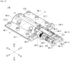
- FIG. 4A is a perspective view of an in-folding hinge assembly IHA viewed from a top surface according to an embodiment of the present disclosure.
- FIG. 4D is a front view of a display apparatus 10 viewed from a front surface according to an embodiment of the present disclosure.
- the in-folding hinge module IHM is accommodated inside the hinge cover HC.
- the lever wing HM-1 (see FIG. 5A ) of the in-folding hinge module IHM rotates according to folding and in-folding.
- the inside of the hinge cover HC may have a half cylinder shape.
- a plurality of partition walls partitioning the inner space of the hinge cover HC may be formed to ensure that the components accommodated in the accommodation space of the hinge cover HC are firmly fixed.
- the components to be accommodated may be firmly fixed by being sandwiched between the portion wall and the partition wall.
- the hinge cover HC may include a plurality of fastening holes.
- the in-folding hinge module IHM may be seated in the accommodation space inside the hinge cover HC. Referring to FIG. 4A , four in-folding hinge modules IHM1, IHM2, IHM3, and IHM4 seated inside the hinge cover HC along the axial direction AD are illustrated. The technical idea of the present disclosure is not limited to the number of in-folding hinge modules IHM1. Some configurations of the in-folding hinge module IHM include configurations that rotate during folding and in-folding and configurations that do not rotate during folding and in-folding. Representatively, the lever wing HM-1 (see FIG. 5A ) may rotate during folding and in-folding. The wing bottom HM-2 (see FIG.
- the in-folding hinge module IHM and the second cover frame CF2 may be coupled to each other through the fastening holes CH10. A detailed description of the in-folding hinge module IHM will be described later with reference to FIG. 5A and the like.
- the up-down plate UDP may have a length along the axial direction AD.
- FIG. 4A illustrates two up-down plates UDP1 and UDP2 as an exemplary number for the in-folding hinge assembly IHA.
- the up-down plate UDP does not rotate during folding and in-folding.
- the up-down plate UDP ascends in the upward direction UD when unfolded.
- the up-down plate UDP descends in the downward direction BD when folded.
- the panel assembly PNLA disposed on the upper portion of the up-down plate UDP may be supported by the up-down plate UDP.
- the folding area FA of the panel PNL may be substantially flat. Accordingly, folding wrinkles that may be formed in the folding area FA of the panel PNL may be removed.
- the up-down plate UDP may be disposed between the in-folding hinge modules IHMs adjacent to each other.
- the up-down plate UDP1 may be disposed between the in-folding hinge module IHM1 and the in-folding hinge module IHM2.
- the up-down plate UDP2 may be disposed between the in-folding hinge module IHM3 and the in-folding hinge module IHM4.
- the up-down plate UDP is coupled to the in-folding hinge module IHM to be able to ascend and descend.
- the up-down plate UDP may include fastening holes CH3. As an exemplary number, two fastening holes CH3 are illustrated.
- the in-folding hinge module IHM1 and the in-folding hinge module IHM2 collectively may include two fastening holes CH4 as an exemplary number.
- the spring Spr1 and the fixing screw SCR are coupled together.
- the up-down plate UDP is coupled to the in-folding hinge module IHM each other so that the up-down plate UDP may be ascended and descended. A detailed description of the up-down plate UDP will be described later with reference to FIG. 7A and the like.
- roller assembly RA and the roller stopper RS A detailed description of the roller assembly RA and the roller stopper RS will be described later with reference to FIG. 7A and the like.
- the pair of lever wings HM-1 and the wing bottom HM-2 are coupled to each other so that the rotation protrusion RB and the rotation guide RG are engaged with each other.
- the pair of lever wings HM-1 rotates to face each other during a folding operation of the display apparatus 10.
- the pair of lever wings HM-1 rotates 180 degrees to each other when the display apparatus 10 is unfolded.
- the wing bottom HM-2 includes an opening OP1.
- the head portion SH of the pair of shafts HM-12 is fastened to the opening OP1.
- the plurality of gear guides HM-4 and the plurality of gears HM-5 are disposed in the upward direction UD of the shaft bottom HM-6.
- the plurality of gear guides HM-4 two may be arranged as an exemplary number along the axial direction AD.
- the plurality of gears HM-5 is disposed between the two gear guides HM-4.
- the plurality of gears HM-5 is illustrated as four.
- the plurality of gear guides HM-4 includes openings OP3.
- the plurality of gears HM-5 includes openings OP4.
- the pair of shafts HM-12 passes through the openings OP3 and OP4. Referring to FIG. 5B , the pair of shafts HM-12 passes through two openings OP3 formed on the outermost side of the openings OP3 formed in the gear guide HM-4 in the side direction SD.
- the pair of shafts HM-12 passes through openings OP4 formed in two outermost gears HM-5 of the plurality of gears HM-5 in the side direction SD.
- the plurality of gears HM-5 rotates.
- the plurality of gear guides HM-4 does not rotate.
- the pair of shafts HM-12 has a length in the axial direction AD.
- the pair of shafts HM-12 is disposed on the upper portion of the shaft bottom HM-6.
- the pair of shafts HM-12 includes a head SH and a tail ST.
- the head SH is fastened to the opening OP1 of the wing bottom HM-2.
- the tail ST is fastened to the opening OP10 of the shaft bottom HM-6.
- FIGS. 6A and 6B the folding and unfolding operation of the display apparatus 10 will also be described in FIG. 6A .
- unnecessary components are omitted.
- a portion of the panel assembly PNLA is additionally illustrated.
- the wing bottom HM-2 is seated in the hinge cover HC.
- the pair of lever wings HM-1 is rotated to face each other. This is because each of the rotation protrusions RB of the pair of lever wings HM-1 rotates in the R1 direction.
- the pair of lever wings HM-1 is connected to the cover frame CF (see FIG. 4D ).
- the fastening hole CH9 is a hole for connecting the first cover frame CF1 (see FIG. 4D ) and one of the pair of lever wings HM-1
- the fastening hole CH10 is a hole for connecting the second cover frame CF2 (see FIG. 4D ) and the other one of the pair of lever wings HM-1.
- FIG. 6C is a perspective view illustrating a folding state of a display apparatus 10 according to an embodiment of the present disclosure.
- the wing bottom HM-2 is seated in the hinge cover HC.
- the fastening hole CH1 formed in the wing bottom HM-2 and the fastening hole CH2 formed in the hinge cover HC are coupled to each other.
- the wing bottom HM-2 may be fixed in the hinge cover HC.
- the cover frame CF (see FIG. 4D ) is connected to the pair of lever wings HM-1 through the fastening hole CH10.
- the pair of lever wings HM-1 is coupled to the pair of wing guides HM-3.
- the wing guide HM-3 includes the sliding protrusion SB, and the lever wing HM-1 includes the sliding guide SG.
- the sliding protrusion SB slides within the sliding guide SG according to the folding and unfolding states.
- the display apparatus 10 according to the present disclosure is folded or unfolded around the folding axis A1.
- the in-folding hinge module IHM according to the present disclosure has two rotational axes by the pair of shafts HM-12.
- the sliding protrusion SB and the sliding guide SG may enable interlocking between the two rotation shafts and the one folding shaft A1 as described above.
- FIG. 7A is a perspective view of a portion of an in-folding hinge assembly IHA according to an embodiment of the present disclosure.
- FIG. 7B is a view illustrating a folding state of an in-folding hinge assembly IHA accordance to an embodiment of the present disclosure, which is a cross-sectional view taken in a direction B-B' in FIG. 7A .
- FIG. 7C is a view illustrating an unfolding state of an in-folding hinge assembly IHA accordance to an embodiment of the present disclosure, which is a cross-sectional view taken in a direction B-B' in FIG. 7A .
- FIGS. 7A to 7E an operation of the up-down plate UDP in the folding and unfolding states of the in-folding hinge assembly IHA according to an embodiment of the present disclosure will be described. For clarity of explanation, unnecessary components are omitted.
- the spring Spr1 may naturally apply a force to lower the up-down plate UDP.
- FIG. 7G is a cross-sectional view illustrating a coupling of an up-down plate UDP, a shaft bottom HM-6, and a hinge cover HC according to an embodiment of the present disclosure.
- the fixing screw SCR may be fastened to the up-down plate UDP.
- a screw thread may be formed on an inner surface of the fastening hole CH3 of the up-down plate UDP, and the fixing screw SCR may be a screw. While being rotated, the fixing screw SCR may be screwed into the fastening hole CH3. Therefore, when the up-down plate UDP ascends and descends, the fixing screw SCR ascends or descends in association with the up-down plate UDP.
- One end of the spring Spr1 is fixed to the shaft bottom HM-6 and the other end of the spring Spr1 is connected to the fixing screw SCR.
- the up-down plate UDP may descend.
- the fixing screw SCR also descends together with the up-down plate UDP. Accordingly, the spring Spr1 is in a relaxed state.
- the up-down plate UDP ascends.
- the fixing screw SCR also ascends together with the up-down plate UDP. Accordingly, the spring Spr1 is in a contracted state.
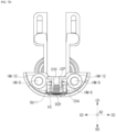
- FIG. 8D is a view illustrating a folding state of an in-folding hinge assembly IHA according to an embodiment of the present disclosure, which is a cross-sectional view taken in a direction D-D' in FIG. 8A .
- FIGS. 8A to 8D operations in the folding and unfolding states of the roller assembly RA and roller stopper RS according to an embodiment of the present disclosure will be described. For clarity of explanation, unnecessary components are omitted.
- the hinge cover HC is illustrated, and the roller stopper RS is seated inside the hinge cover HC.
- the roller stopper RS includes the fastening hole CH5.
- the hinge cover HC includes the fastening hole CH6 (see FIG. 4B ).
- the fastening hole CH5 and the fastening hole CH6 may be coupled to each other, and thus, the roller stopper RS may be fixed in the inner accommodation space of the hinge cover HC.
- each of the fastening hole CH5 and the fastening hole CH6 may be illustratively two.
- the roller R may be a cylindrical roller having a length in the axial direction AD.
- the roller R may rotate about a rolling axis.
- the rolling axis is in the same direction as the axial direction AD.
- the outer circumferential surface of the roller R may contact the side surface of the roller stopper RS in an unfolding state, and may not contact the side surface of the roller stopper RS in a folding state.
- the roller R may be formed of a material having elasticity.
- the roller R may be formed of rubber or elastic foam. If the roller R is formed of a material having elasticity, its adhesive force may be strengthened when the roller R contacts the roller stopper RS.
- a spring holder RSH is disposed inside the inner housing RIH.
- the spring holder RSH may be integral with the inner housing RIH. That is, the spring holder RSH may have a pillar shape from which the inner housing RIH protrudes.
- the spring holder RSH may be a pillar having a long shape in the side direction SD.
- a spring Spr2 is inserted into the spring holder RSH.
- the spring Spr2 is not limited to that term and may be of another type having elasticity.
- the spring Spr2 may be disposed to have a length in the side direction SD.
- One side of the spring Spr2 contacts the outer housing ROH, and the other side of the spring Spr2 contacts the inner housing RIH.
- the length of the inner housing RIH in the side direction SD is shorter than the length of the outer housing ROH in the side direction SD. Accordingly, the inner housing RIH may reciprocate inside the outer housing ROH.
- the respective four spring holders RSH and the respective four springs Spr2 are illustrated as an exemplary number.
- the in-folding hinge assembly IHA is in an unfolding state.
- the first cover frame CF1 and the second cover frame CF2 are disposed to form 180 degrees from each other.
- the outer housing ROH is fixed to the cover frames CF1 and CF2. Therefore, in the unfolding state, the outer housing ROH is fixed without moving in the side direction SD.
- the inner housing RIH is disposed within the outer housing ROH.
- the inner housing RIH may reciprocate in the side direction SD inside the outer housing ROH.
- the roller R is fixed to the inner housing RIH. Accordingly, the roller R reciprocates with the inner housing RIH.
- the spring Spr2 is inserted into the spring holder RSH. One side of the spring Spr2 contacts the outer housing ROH, and the other side of the spring Spr2 contacts the inner housing RIH.
- the spring Spr2 generates a force for the reciprocating motion of the inner housing RIH.
- the roller R When the in-folding hinge assembly IHA is unfolded, the roller R contacts the roller stopper RS while being disposed in the side direction SD of the roller stopper RS. Since the roller stopper RS is fixed while the roller R is movable, the roller R moves in the direction of the outer housing ROH. Thus, the distance D1 between the roller R and the outer housing ROH is reduced. As the roller R moves, the inner housing RIH also moves in the direction of the outer housing ROH. Accordingly, the spring Spr2 contracts. When compared with the distance D2 described later with reference to FIG. 8D , the distance D1 is shorter than the distance D2.
- the repulsive force F1 is a force that compresses the roller R with the roller stopper RS. Due to the repulsive force F 1, the unfolding state of the display apparatus 10 may be more firmly fixed in the unfolding state. Also, the display apparatus 10 may implement a substantially perfect plane in an unfolding state. In addition, the above-described up-down plate UDP (see FIG. 7A ) may be further raised. Accordingly, it is possible to completely remove folding wrinkles that may occur in the folding area FA (see FIG. 3 ).
- the in-folding hinge assembly IHA is in a folding state.
- the first cover frame CF1 and the second cover frame CF2 are disposed to face each other.
- the outer housing ROH is fixed to the cover frames CF1 and CF2. Therefore, in the folding state, the outer housing ROH is fixed without moving in the upward direction UD and the downward direction BD.
- the inner housing RIH is disposed within the outer housing ROH.
- the inner housing RIH may reciprocate in the upward direction UD and the downward direction BD within the outer housing ROH.
- the roller R is fixed to the inner housing RIH. Accordingly, the roller R reciprocates with the inner housing RIH.
- the spring Spr2 is inserted into spring holder RSH. One side of the spring Spr2 contacts the outer housing ROH, and the other side of the spring Spr2 contacts the inner housing RIH.
- the spring Spr2 generates a force for the reciprocating movement of the inner housing RIH.
- the roller R When the in-folding hinge assembly IHA is folded, the roller R is disposed in the upward direction UD of the roller stopper RS and does not contact the roller stopper RS. Thus, the spring Spr2 relaxes. When the spring Spr2 is relaxed, the spring Spr2 moves the inner housing RIH in the downward direction BD. Accordingly, the distance D2 between the outer housing ROH and the roller R is greater than the distance D1 in the unfolding state.
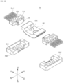
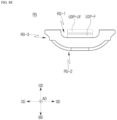
- FIG. 8E is a front view illustrating a roller stopper RS according to an embodiment of the present disclosure. For clarity of explanation, the components illustrated are illustrated in a more enlarged state compared to other figures.
- the roller stopper RS includes a concave portion RS-1 on a surface in the upward direction UD.
- the up-down plates UDF-UF and UDP-F may be disposed in the concave portion RS-1.
- the up-down plates UDP-UF and UDP-F may ascend in the upward direction UD or descend in the downward direction BD from the inside of the concave portion RS-1.
- the height of the concave portion RS-1 may be higher than that of the up-down plates UDP-UF and UDP-F.
- the up-down plate UDP-UF may be positioned relatively high within the concave portion RS-1.
- a surface of the up-down plate UDP-UF in the upward direction UD may be substantially the same as a surface of the roller stopper RS in the upward direction UD.
- the up-down plate UDP-F may be positioned relatively low in the concave portion RS-1.
- the surface of the up-down plate UDP-F in the upward direction UD may be lower than the surface of the roller stopper RS in the upward direction UD.
- the roller stopper RS includes a convex portion RS-2 on the surface in the downward direction BD.
- the convex portion RS-2 may have, for example, a half cylinder shape.
- the convex portion RS-2 may have a shape corresponding to the hinge cover HC (see FIG. 4B ).
- the hinge cover HC may include the fastening hole CH6 (see FIG. 4B ), and the roller stopper RS may include the fastening hole CH5 (see FIG. 4C ).
- the hinge cover HC and the roller stopper RS may be coupled to each other through the fastening holes CH5 and CH6.
- the roller stopper RS may be fixed to the hinge cover HC.
- the roller stopper RS includes an inclined portion RS-3 in the surface in the side direction SD. As described above with reference to FIGS. 8C and 8D , in the folding state, the roller R is disposed in the upward direction UD of the roller stopper RS, but in the unfolding state, the roller R is disposed in the side direction SD of the roller stopper RS. When switching from a folding state to an unfolding state, the roller R may move along the inclined portion. Therefore, natural movement of the roller R is possible. Conversely, natural movement of the roller R is possible even when switching from the unfolding state to the folding state. Due to the natural movement of the roller R, it is possible to smoothly switch between the folding state and unfolding state of the display apparatus 10.
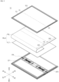
- FIG. 9 is an exploded perspective view of a display apparatus 10 according to another embodiment of the present disclosure.
- a direction along the folding axis A1 in which the display apparatus 10 is folded is defined as an axial direction AD.
- a direction starting from the first display area DA1, passing through the folding area FA and arriving at the second display area DA2 in the display apparatus 10 is defined as a side direction SD.
- a direction in which the panel PNL of the display apparatus 10 faces is defined as an upward direction UD.
- a direction opposite to the upward direction UD is defined as a downward direction BD.
- the top frame TF is disposed at the top of the display apparatus 10 in the upward direction UD.
- the top frame TF includes a first top frame TF1 disposed on one side of the folding axis A1 and a second top frame TF2 disposed on the other side of the folding axis A1.
- the top frame TF is disposed to cover the edge of the panel PNL.
- the top frame TF may protect the panel PNL from external impact.
- the top frame TF may form a bezel of the display apparatus.
- the panel assembly PNLA is disposed on the lower portion of the top frame TF.
- the panel assembly PNLA includes a panel PNL and one or more plates PLTs.
- the panel PNL may include a flexible substrate, a circuit element layer disposed on the flexible substrate and including transistors, a light emitting layer disposed on the circuit element layer and including light emitting elements, an encapsulation layer disposed on the light emitting layer, and a touch layer disposed on the encapsulation layer or disposed inside the encapsulation layer.
- the panel PNL may include a first display area DA1, a folding area FA, and a second display area DA2.
- one or more plates PLTs may include various plates disposed on the lower portion of the panel PNL to support the panel PNL.
- the one or more plates may include a back plate to support the panel PNL, a top plate disposed on the lower portion of the back plate and formed of a SUS material, a bottom plate disposed on the lower portion of the top plate, formed with a pattern on a folding portion and formed of a SUS material, a heat dissipation sheet with heat dissipation function, and a middle plate to cover non-leveled planes due to various configurations of the hinge assembly.
- the in-folding hinge assembly IHA is disposed on the lower portion of the folding area FA.
- the in-folding hinge assembly IHA may have a long shape along the axial direction AD.
- the in-folding hinge assembly IHA may perform folding and unfolding operations based on the folding axis A1.
- the cover frame CF is a frame covering the side surface and lower surface of the display apparatus 10.
- An accommodation groove in which the in-folding hinge assembly IHA may be seated may be formed on the upper surface of the cover frame CF.
- the cover frame CF includes a first cover frame CF1 disposed on one side and a second cover frame CF2 disposed on the other side, based on the folding axis A1.
- the cover frame CF is coupled to the in-folding hinge assembly IHA.
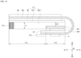
- FIG. 10 is a cross-sectional view of a display apparatus 10 according to another embodiment of the present disclosure.
- the back plate BP may be formed of a relatively hard material to supplement the rigidity of the flexible panel PNL.
- the back plate BP may be formed of a plastic material or a metal material.
- the top plate TPLT is a plate for supplementing the rigidity of the panel PNL while supplementing the foldable characteristics of the display apparatus 10.
- the top plate TPLT may be formed of a plastic or metal material.
- the top plate TPLT may be formed of a SUS material.
- the SUS material may be a stainless steel material.
- the bottom plate BPLT is a plate for supplementing the rigidity of the panel PNL while supplementing the foldable characteristics of the display apparatus 10.
- the bottom plate BPLT may be formed of a plastic or metal material.
- the bottom plate BPLT may be formed of a SUS material.
- the bottom plate BPLT may be formed thicker than that of the top plate TPLT.
- the bottom plate BPLT may include a slit pattern PTN in a portion corresponding to the folding area FA (see FIG. 9 ).
- An adhesive member ADH is disposed on the lower portion of the heat dissipation sheet GST.
- the adhesive member ADH may serve to adhere the heat dissipation sheet GST and the back plate BP to each other.
- the adhesive member ADH may be, for example, a foam tape or a pressure sensitive adhesive PSA, but is not limited thereto.
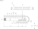
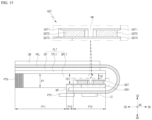
- the integrated circuit IC is disposed on the lower portion of the bent portion of the panel PNL.
- the integrated circuit IC may be formed using a chip on glass (COG) scheme.
- the integrated circuit IC may be, for example, a source driver.
- the integrated circuit IC may be a gate driver or a power control circuit.
- the integrated circuit IC may be positioned on the second part PT2 of the bottom plate BPLT.
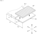
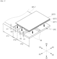
- FIG. 13 is a perspective view of a display apparatus 10 according to an embodiment of the present disclosure.
- a vertical wall VW is disposed on the second part PT2.
- the vertical wall VW may have a first height H1. Accordingly, the accommodation space SPC (see FIGS. 13 and 14 ) formed in the second part PT2 may be divided by the vertical wall VW.
- the first adhesive surface GST1 and the second adhesive surface GST3 may be made of an adhesive material.
- the adhesive material may include, for example, a foam tape or a double-sided tape, but is not limited thereto.
- the first adhesive surface GST1 may attach the heat dissipation sheet GST to the bottom plate BPLT.
- the second adhesive surface GST3 may attach the heat dissipation sheet GST to the adhesive member ADH.
- the vertical wall VW may be formed along the axial direction AD and the side direction SD. Accordingly, a plurality of accommodation spaces SPCs may be formed in a matrix form.
- a heat dissipation sheet GST may be disposed in each of the plurality of accommodation spaces SPCs.
- a plurality of heat dissipation sheets GST may be formed in a matrix form.
- the heat dissipation sheet GST may include a first adhesive surface GST1, a heat dissipation material GST2, and a second adhesive surface GST3.
- FIG. 17 is a perspective view of a display apparatus 10 according to another embodiment of the present disclosure.
- FIGS. 15 to 17 Another embodiment of the present disclosure will be described with reference to FIGS. 15 to 17 .
- the same or similar figures and the same or similar reference numerals may refer to the same or similar configurations as those of the foregoing embodiment.
- the embodiment may be illustrated or described with omission of some components.
- the embodiment may be illustrated or described without addition of some components.
- a cover window CW, a panel PNL, and one or more plates PLTs are disposed from an upward direction UD to a downward direction BD.
- One or more plates PLTs may include a back plate BP, a top plate TPLT, and a bottom plate BPLT.
- the bottom plate BPLT may include a slit pattern PTN in a portion corresponding to the folding area FA (see FIG. 9 ).
- the lift protrusion LB may rotate between a downward direction position and a side direction position.
- the lift protrusion LB When the foldable display apparatus is folded, the lift protrusion LB is positioned in a downward direction, and the lift protrusion LB may not contact the up-down plate UDP.
- the in-folding hinge assembly IHA may further include a shaft bottom HM-6 disposed in a downward direction of the up-down plate UDP and an upward direction of the hinge cover HC.
- the fastening hole CH3 may be disposed to pass through the fastening hole CH4.
- the spring Spr1 When the foldable display apparatus is folded, the spring Spr1 may be relaxed, and the spring Spr1 may lower the up-down plate UDP.
- the roller When the foldable display apparatus is folded, the roller may be disposed in the upward direction of the roller stopper RS.
- the roller stopper RS may include an inclined portion RS-3 on a surface of a side direction.
- the in-folding hinge assembly may include a first in-folding hinge module IHM1 and second in-folding hinge module IHM2 disposed adjacently along the axial direction, and the roller stopper RS may be disposed between the first in-folding hinge module IHM1 and the second in-folding hinge module IHM2.
- a foldable display apparatus comprising a panel assembly including a panel including a first display area, a second display area, and a folding area, and one or more plates disposed on a lower portion of the panel; an in-folding hinge assembly that is disposed in the folding area under the panel assembly and includes a hinge cover; and first and second cover frames that are coupled to the in-folding hinge assembly, wherein the one or more plates include a bottom plate, and wherein the bottom plate includes a first part having a first height and a second part having a second height lower than the first height, is disclosed.
- the bottom plate may be formed of a SUS material.
- the bottom plate may include a slit pattern corresponding to the folding area.
- the foldable display apparatus may further comprise an integrated circuit disposed on a lower portion of the second part.
- the foldable display apparatus may further comprise a heat dissipation sheet disposed in an accommodation space formed in the second part.
- the heat dissipation sheet may include a graphite material.
- the heat dissipation sheet may include a first adhesive surface, a heat dissipation material, and a second adhesive surface.
- the bottom plate may further include a vertical wall formed in the second part.
- the vertical wall may be formed along an axial direction.
- the vertical wall may be formed along an axial direction and a side direction.
- the bottom plate may further include a third part that is formed between the first part and the second part and has a third height lower than the first height and higher than the second height.
- the foldable display apparatus may further comprise an accommodation space formed in the second part and a heat dissipation sheet disposed in the third part.
- the heat dissipation sheet may include a plurality of first adhesive surfaces, a plurality of heat dissipation materials, and a second adhesive surface attached to the plurality of heat dissipation materials.
- the second adhesive surface may be formed in plurality, and each of the second adhesive surfaces may be attached to each of the plurality of heat dissipation materials.
- the second adhesive surface may be integrally formed, and the plurality of heat dissipation materials may be attached to the integral second adhesive surface.
- the in-folding hinge assembly may further include an up-down plate having a length in an axial direction.
- the in-folding hinge assembly may further include a lift washer having a lift protrusion.
- the lift protrusion may rotate between a downward direction position and a side direction position.
- the lift protrusion When the foldable display apparatus is folded, the lift protrusion may be positioned in a downward direction, and the lift protrusion may not contact the up-down plate.
- the lift protrusion When the foldable display apparatus is unfolded, the lift protrusion may be positioned in a side direction, and the lift protrusion may support the up-down plate.
Landscapes
- Engineering & Computer Science (AREA)
- Theoretical Computer Science (AREA)
- Computer Hardware Design (AREA)
- General Engineering & Computer Science (AREA)
- Physics & Mathematics (AREA)
- General Physics & Mathematics (AREA)
- Human Computer Interaction (AREA)
- Signal Processing (AREA)
- Mechanical Engineering (AREA)
- Devices For Indicating Variable Information By Combining Individual Elements (AREA)
- Mathematical Physics (AREA)
- Microelectronics & Electronic Packaging (AREA)
- Thermal Sciences (AREA)
- Pivots And Pivotal Connections (AREA)
- Road Signs Or Road Markings (AREA)
Applications Claiming Priority (1)
| Application Number | Priority Date | Filing Date | Title |
|---|---|---|---|
| KR1020220190198A KR20240107492A (ko) | 2022-12-30 | 2022-12-30 | 폴더블 표시 장치 |
Publications (2)
| Publication Number | Publication Date |
|---|---|
| EP4394549A2 true EP4394549A2 (de) | 2024-07-03 |
| EP4394549A3 EP4394549A3 (de) | 2024-09-11 |
Family
ID=89224175
Family Applications (1)
| Application Number | Title | Priority Date | Filing Date |
|---|---|---|---|
| EP23218541.3A Pending EP4394549A3 (de) | 2022-12-30 | 2023-12-20 | Faltbare anzeigevorrichtung |
Country Status (5)
| Country | Link |
|---|---|
| US (1) | US20240219964A1 (de) |
| EP (1) | EP4394549A3 (de) |
| JP (2) | JP7662761B2 (de) |
| KR (1) | KR20240107492A (de) |
| CN (1) | CN118280212A (de) |
Families Citing this family (4)
| Publication number | Priority date | Publication date | Assignee | Title |
|---|---|---|---|---|
| KR20230097763A (ko) * | 2021-12-24 | 2023-07-03 | 엘지디스플레이 주식회사 | 폴더블 표시 장치 |
| TWI853352B (zh) * | 2022-11-28 | 2024-08-21 | 富世達股份有限公司 | 鉸鏈 |
| KR20240104909A (ko) * | 2022-12-28 | 2024-07-05 | 엘지디스플레이 주식회사 | 표시장치 |
| KR20260023771A (ko) | 2024-08-12 | 2026-02-20 | 현대모비스 주식회사 | 배터리셀 어셈블리 |
Family Cites Families (13)
| Publication number | Priority date | Publication date | Assignee | Title |
|---|---|---|---|---|
| JPH03105880U (de) * | 1990-02-13 | 1991-11-01 | ||
| JP2013174692A (ja) * | 2012-02-24 | 2013-09-05 | Sony Corp | 表示装置 |
| JP6826881B2 (ja) * | 2016-12-22 | 2021-02-10 | 株式会社ジャパンディスプレイ | 保護部材、表示装置および表示装置の製造方法 |
| CN108573656A (zh) * | 2017-03-14 | 2018-09-25 | 昆山工研院新型平板显示技术中心有限公司 | 一种柔性显示屏以及柔性显示装置 |
| KR102540815B1 (ko) * | 2018-06-01 | 2023-06-08 | 삼성전자주식회사 | 폴더블 디스플레이를 포함하는 전자 장치 |
| CN108712535A (zh) * | 2018-06-28 | 2018-10-26 | 努比亚技术有限公司 | 可折叠的移动终端 |
| KR102563626B1 (ko) * | 2019-01-09 | 2023-08-04 | 삼성전자 주식회사 | 플렉서블 디스플레이 및 이를 포함하는 전자장치 |
| KR102375556B1 (ko) * | 2019-04-30 | 2022-03-17 | 삼성전자주식회사 | 힌지 구조물 및 이를 포함하는 전자 장치 |
| KR102751451B1 (ko) * | 2019-10-22 | 2025-01-10 | 삼성전자주식회사 | 디스플레이 보호 구조를 포함하는 폴더블 전자 장치 |
| EP3958092A1 (de) * | 2020-08-21 | 2022-02-23 | Samsung Display Co., Ltd. | Anzeigevorrichtung |
| KR102711319B1 (ko) * | 2020-08-24 | 2024-09-26 | 엘지디스플레이 주식회사 | 디스플레이 모듈 및 디스플레이 장치 |
| EP4254918A4 (de) * | 2021-04-20 | 2024-07-24 | Samsung Electronics Co., Ltd. | Elektronische vorrichtung mit öffnungsstruktur |
| US11907031B2 (en) * | 2021-05-21 | 2024-02-20 | Samsung Display Co., Ltd. | Display device and electronic device including the same |
-
2022
- 2022-12-30 KR KR1020220190198A patent/KR20240107492A/ko active Pending
-
2023
- 2023-12-14 US US18/540,157 patent/US20240219964A1/en active Pending
- 2023-12-20 EP EP23218541.3A patent/EP4394549A3/de active Pending
- 2023-12-22 CN CN202311788804.8A patent/CN118280212A/zh active Pending
- 2023-12-27 JP JP2023220352A patent/JP7662761B2/ja active Active
-
2025
- 2025-04-03 JP JP2025061711A patent/JP2025100960A/ja active Pending
Also Published As
| Publication number | Publication date |
|---|---|
| US20240219964A1 (en) | 2024-07-04 |
| CN118280212A (zh) | 2024-07-02 |
| JP2024096061A (ja) | 2024-07-11 |
| JP7662761B2 (ja) | 2025-04-15 |
| EP4394549A3 (de) | 2024-09-11 |
| KR20240107492A (ko) | 2024-07-09 |
| JP2025100960A (ja) | 2025-07-04 |
Similar Documents
| Publication | Publication Date | Title |
|---|---|---|
| EP4394549A2 (de) | Faltbare anzeigevorrichtung | |
| KR102806807B1 (ko) | 플렉시블 디스플레이 어셈블리 및 이를 포함하는 전자 장치 | |
| EP4358495A1 (de) | Elektronische vorrichtung mit anzeigeträgerstruktur | |
| CN119301937A (zh) | 包括铰链装置的电子装置 | |
| CN102282535A (zh) | 便携式显示装置 | |
| WO2023109549A1 (zh) | 一种电子设备 | |
| JP2023514892A (ja) | シーリング部材を含む電子装置 | |
| WO2020108247A1 (zh) | 移动终端 | |
| CN106371513A (zh) | 智能终端 | |
| KR20250125435A (ko) | 휴대용 표시장치 | |
| KR102884204B1 (ko) | 실링 부재를 포함하는 전자 장치 | |
| KR102637426B1 (ko) | 롤러블 디스플레이 장치 | |
| KR20240107498A (ko) | 폴더블 표시 장치 | |
| EP4668724A2 (de) | Elektronische vorrichtung mit scharniervorrichtung | |
| KR20240107795A (ko) | 폴더블 표시 장치 | |
| KR20240107496A (ko) | 폴더블 표시 장치 | |
| KR20240107494A (ko) | 폴더블 표시 장치 | |
| KR20240107495A (ko) | 폴더블 표시 장치 | |
| KR20240107491A (ko) | 폴더블 표시 장치 | |
| KR20240107493A (ko) | 폴더블 표시 장치 | |
| KR20240107986A (ko) | 폴더블 표시 장치 | |
| EP4083747B1 (de) | Elektronische vorrichtung mit anzeige | |
| KR20240041782A (ko) | 연성 기판을 포함하는 전자 장치 | |
| CN110519426B (zh) | 移动终端 | |
| JP2024504748A (ja) | 破損防止構造を含む電子装置 |
Legal Events
| Date | Code | Title | Description |
|---|---|---|---|
| PUAI | Public reference made under article 153(3) epc to a published international application that has entered the european phase |
Free format text: ORIGINAL CODE: 0009012 |
|
| STAA | Information on the status of an ep patent application or granted ep patent |
Free format text: STATUS: REQUEST FOR EXAMINATION WAS MADE |
|
| 17P | Request for examination filed |
Effective date: 20231220 |
|
| AK | Designated contracting states |
Kind code of ref document: A2 Designated state(s): AL AT BE BG CH CY CZ DE DK EE ES FI FR GB GR HR HU IE IS IT LI LT LU LV MC ME MK MT NL NO PL PT RO RS SE SI SK SM TR |
|
| PUAL | Search report despatched |
Free format text: ORIGINAL CODE: 0009013 |
|
| AK | Designated contracting states |
Kind code of ref document: A3 Designated state(s): AL AT BE BG CH CY CZ DE DK EE ES FI FR GB GR HR HU IE IS IT LI LT LU LV MC ME MK MT NL NO PL PT RO RS SE SI SK SM TR |
|
| RIC1 | Information provided on ipc code assigned before grant |
Ipc: H04M 1/02 20060101ALI20240807BHEP Ipc: G06F 1/20 20060101ALI20240807BHEP Ipc: G06F 1/16 20060101AFI20240807BHEP |
|
| STAA | Information on the status of an ep patent application or granted ep patent |
Free format text: STATUS: EXAMINATION IS IN PROGRESS |
|
| 17Q | First examination report despatched |
Effective date: 20251015 |