EP4394440A1 - Verfahren zur erfassung von installationsanomalien einer erfassungsvorrichtung und erfassungsvorrichtung zur durchführung davon - Google Patents
Verfahren zur erfassung von installationsanomalien einer erfassungsvorrichtung und erfassungsvorrichtung zur durchführung davon Download PDFInfo
- Publication number
- EP4394440A1 EP4394440A1 EP22861629.8A EP22861629A EP4394440A1 EP 4394440 A1 EP4394440 A1 EP 4394440A1 EP 22861629 A EP22861629 A EP 22861629A EP 4394440 A1 EP4394440 A1 EP 4394440A1
- Authority
- EP
- European Patent Office
- Prior art keywords
- static
- sensing device
- object area
- dimensional space
- point
- Prior art date
- Legal status (The legal status is an assumption and is not a legal conclusion. Google has not performed a legal analysis and makes no representation as to the accuracy of the status listed.)
- Pending
Links
Images


Classifications
-
- G—PHYSICS
- G01—MEASURING; TESTING
- G01S—RADIO DIRECTION-FINDING; RADIO NAVIGATION; DETERMINING DISTANCE OR VELOCITY BY USE OF RADIO WAVES; LOCATING OR PRESENCE-DETECTING BY USE OF THE REFLECTION OR RERADIATION OF RADIO WAVES; ANALOGOUS ARRANGEMENTS USING OTHER WAVES
- G01S7/00—Details of systems according to groups G01S13/00, G01S15/00, G01S17/00
- G01S7/48—Details of systems according to groups G01S13/00, G01S15/00, G01S17/00 of systems according to group G01S17/00
- G01S7/497—Means for monitoring or calibrating
-
- G—PHYSICS
- G01—MEASURING; TESTING
- G01S—RADIO DIRECTION-FINDING; RADIO NAVIGATION; DETERMINING DISTANCE OR VELOCITY BY USE OF RADIO WAVES; LOCATING OR PRESENCE-DETECTING BY USE OF THE REFLECTION OR RERADIATION OF RADIO WAVES; ANALOGOUS ARRANGEMENTS USING OTHER WAVES
- G01S17/00—Systems using the reflection or reradiation of electromagnetic waves other than radio waves, e.g. lidar systems
- G01S17/02—Systems using the reflection of electromagnetic waves other than radio waves
- G01S17/06—Systems determining position data of a target
- G01S17/42—Simultaneous measurement of distance and other co-ordinates
-
- G—PHYSICS
- G01—MEASURING; TESTING
- G01S—RADIO DIRECTION-FINDING; RADIO NAVIGATION; DETERMINING DISTANCE OR VELOCITY BY USE OF RADIO WAVES; LOCATING OR PRESENCE-DETECTING BY USE OF THE REFLECTION OR RERADIATION OF RADIO WAVES; ANALOGOUS ARRANGEMENTS USING OTHER WAVES
- G01S17/00—Systems using the reflection or reradiation of electromagnetic waves other than radio waves, e.g. lidar systems
- G01S17/88—Lidar systems specially adapted for specific applications
- G01S17/89—Lidar systems specially adapted for specific applications for mapping or imaging
- G01S17/894—Three-dimensional [3D] imaging with simultaneous measurement of time-of-flight at a two-dimensional [2D] array of receiver pixels, e.g. time-of-flight cameras or flash lidar
-
- G—PHYSICS
- G01—MEASURING; TESTING
- G01S—RADIO DIRECTION-FINDING; RADIO NAVIGATION; DETERMINING DISTANCE OR VELOCITY BY USE OF RADIO WAVES; LOCATING OR PRESENCE-DETECTING BY USE OF THE REFLECTION OR RERADIATION OF RADIO WAVES; ANALOGOUS ARRANGEMENTS USING OTHER WAVES
- G01S17/00—Systems using the reflection or reradiation of electromagnetic waves other than radio waves, e.g. lidar systems
- G01S17/88—Lidar systems specially adapted for specific applications
- G01S17/93—Lidar systems specially adapted for specific applications for anti-collision purposes
- G01S17/931—Lidar systems specially adapted for specific applications for anti-collision purposes of land vehicles
-
- G—PHYSICS
- G01—MEASURING; TESTING
- G01S—RADIO DIRECTION-FINDING; RADIO NAVIGATION; DETERMINING DISTANCE OR VELOCITY BY USE OF RADIO WAVES; LOCATING OR PRESENCE-DETECTING BY USE OF THE REFLECTION OR RERADIATION OF RADIO WAVES; ANALOGOUS ARRANGEMENTS USING OTHER WAVES
- G01S7/00—Details of systems according to groups G01S13/00, G01S15/00, G01S17/00
- G01S7/48—Details of systems according to groups G01S13/00, G01S15/00, G01S17/00 of systems according to group G01S17/00
- G01S7/4808—Evaluating distance, position or velocity data
-
- G—PHYSICS
- G01—MEASURING; TESTING
- G01S—RADIO DIRECTION-FINDING; RADIO NAVIGATION; DETERMINING DISTANCE OR VELOCITY BY USE OF RADIO WAVES; LOCATING OR PRESENCE-DETECTING BY USE OF THE REFLECTION OR RERADIATION OF RADIO WAVES; ANALOGOUS ARRANGEMENTS USING OTHER WAVES
- G01S7/00—Details of systems according to groups G01S13/00, G01S15/00, G01S17/00
- G01S7/48—Details of systems according to groups G01S13/00, G01S15/00, G01S17/00 of systems according to group G01S17/00
- G01S7/497—Means for monitoring or calibrating
- G01S7/4972—Alignment of sensor
-
- G—PHYSICS
- G06—COMPUTING OR CALCULATING; COUNTING
- G06T—IMAGE DATA PROCESSING OR GENERATION, IN GENERAL
- G06T17/00—Three-dimensional [3D] modelling for computer graphics
- G06T17/05—Geographic models
-
- G—PHYSICS
- G06—COMPUTING OR CALCULATING; COUNTING
- G06T—IMAGE DATA PROCESSING OR GENERATION, IN GENERAL
- G06T7/00—Image analysis
- G06T7/10—Segmentation; Edge detection
- G06T7/11—Region-based segmentation
-
- G—PHYSICS
- G06—COMPUTING OR CALCULATING; COUNTING
- G06T—IMAGE DATA PROCESSING OR GENERATION, IN GENERAL
- G06T7/00—Image analysis
- G06T7/70—Determining position or orientation of objects or cameras
- G06T7/73—Determining position or orientation of objects or cameras using feature-based methods
-
- G—PHYSICS
- G06—COMPUTING OR CALCULATING; COUNTING
- G06V—IMAGE OR VIDEO RECOGNITION OR UNDERSTANDING
- G06V10/00—Arrangements for image or video recognition or understanding
- G06V10/40—Extraction of image or video features
- G06V10/62—Extraction of image or video features relating to a temporal dimension, e.g. time-based feature extraction; Pattern tracking
-
- G—PHYSICS
- G06—COMPUTING OR CALCULATING; COUNTING
- G06V—IMAGE OR VIDEO RECOGNITION OR UNDERSTANDING
- G06V20/00—Scenes; Scene-specific elements
- G06V20/50—Context or environment of the image
- G06V20/52—Surveillance or monitoring of activities, e.g. for recognising suspicious objects
-
- G—PHYSICS
- G06—COMPUTING OR CALCULATING; COUNTING
- G06V—IMAGE OR VIDEO RECOGNITION OR UNDERSTANDING
- G06V20/00—Scenes; Scene-specific elements
- G06V20/50—Context or environment of the image
- G06V20/56—Context or environment of the image exterior to a vehicle by using sensors mounted on the vehicle
-
- G—PHYSICS
- G06—COMPUTING OR CALCULATING; COUNTING
- G06V—IMAGE OR VIDEO RECOGNITION OR UNDERSTANDING
- G06V20/00—Scenes; Scene-specific elements
- G06V20/60—Type of objects
- G06V20/64—Three-dimensional [3D] objects
-
- G—PHYSICS
- G06—COMPUTING OR CALCULATING; COUNTING
- G06T—IMAGE DATA PROCESSING OR GENERATION, IN GENERAL
- G06T2207/00—Indexing scheme for image analysis or image enhancement
- G06T2207/10—Image acquisition modality
- G06T2207/10016—Video; Image sequence
-
- G—PHYSICS
- G06—COMPUTING OR CALCULATING; COUNTING
- G06T—IMAGE DATA PROCESSING OR GENERATION, IN GENERAL
- G06T2207/00—Indexing scheme for image analysis or image enhancement
- G06T2207/10—Image acquisition modality
- G06T2207/10028—Range image; Depth image; 3D point clouds
-
- G—PHYSICS
- G06—COMPUTING OR CALCULATING; COUNTING
- G06T—IMAGE DATA PROCESSING OR GENERATION, IN GENERAL
- G06T2207/00—Indexing scheme for image analysis or image enhancement
- G06T2207/30—Subject of image; Context of image processing
- G06T2207/30232—Surveillance
-
- G—PHYSICS
- G06—COMPUTING OR CALCULATING; COUNTING
- G06T—IMAGE DATA PROCESSING OR GENERATION, IN GENERAL
- G06T2207/00—Indexing scheme for image analysis or image enhancement
- G06T2207/30—Subject of image; Context of image processing
- G06T2207/30236—Traffic on road, railway or crossing
-
- G—PHYSICS
- G06—COMPUTING OR CALCULATING; COUNTING
- G06T—IMAGE DATA PROCESSING OR GENERATION, IN GENERAL
- G06T2207/00—Indexing scheme for image analysis or image enhancement
- G06T2207/30—Subject of image; Context of image processing
- G06T2207/30244—Camera pose
Definitions
- the disclosure relates to a method of sensing an installation abnormality of a sensing device and a sensing device for performing the same.
- a computer-readable storage medium having recorded thereon a program to be executed on a computer includes instructions to obtain point clouds over time with respect to a three-dimensional space by using a LiDAR sensor, instructions to determine a static object area of the three-dimensional space, based on instructions based on the obtained point clouds over time with respect to the three-dimensional space, and instructions to determine an installation abnormality of a sensing device based on static point clouds having a certain time difference among static point clouds over time corresponding to the determined static object area.
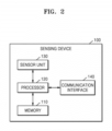
- a sensing device includes a sensor unit configured to obtain point clouds over time with respect to a three-dimensional space by using a LiDAR sensor, a memory storing one or more instructions, and a processor configured to, by executing the one or more instructions, determine the static object area of the three-dimensional space based on the obtained point clouds over time with respect to the three-dimensional space, and determine an installation abnormality of the sensing device based on static point clouds having a certain time difference among static point clouds over time corresponding to the determined static object area.
- the sensing device 100 may include a light detection and ranging (LiDAR) sensor as a 3D sensor for sending a three-dimensional space and may obtain volumetric point cloud data.
- the sensing device 100 may further include, as necessary, various types of sensors, such as a radar sensor, an infrared image sensor, a camera, and the like.
- the sensing device 100 may use a plurality of homogeneous sensors or a combination of heterogeneous sensors, considering a detection range that each type of sensor has or the type of data that can be obtained, and the like.
- the memory 110 may store software and/or a program.
- the memory 110 may store instructions to be executable by the processor 120.
- the point cloud of a three-dimensional space may be obtained by using a LiDAR sensor, and an object in the three-dimensional space may be identified based on the obtained point cloud of a three-dimensional space.
- the processor 120 may identify static objects such as the ground or buildings or dynamic objects such as animals, by applying the point cloud of a three-dimensional space to the object classification model or clustering the point cloud of a three-dimensional space.
- a method of distinguishing a dynamic point cloud corresponding to a dynamic object from a static point cloud corresponding to a static object in space information map, and a method of determining a static object area in a space information map, are described below with reference to FIGS. 3 to 5 .
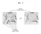
- FIG. 3 is a view for explaining a dynamic point cloud, a static point cloud, and a static object area in the space information map generated by the sensing device 100.
- the space information map of FIG. 3 may be obtained by the sensing device 100 using a LiDAR sensor by installing the sensing device 100 at a position where the intersection through which vehicles move can be observed, and may be used to monitor the traffic information of an intersection that is the area of interest.
- point clouds corresponding to vehicles and pedestrians moving and stopping according to traffic signals at the intersection point clouds corresponding to vehicles and pedestrians moving and stopping according to traffic signals at the intersection.
- the vehicles and pedestrians that move correspond to dynamic objects, and the positions of the dynamic point clouds corresponding to dynamic objects are changed in the space information map so that the dynamic point clouds are not continuously detected in the same area for more than a certain period.
- traffic infrastructure, roads, buildings, and the like of the intersection are not moving correspond to static objects, and these static point clouds corresponding to the static objects may be continuously detected in the same area of the space information map for more than a certain period.
- the point cloud When a point cloud is continuously detected in a specific area corresponding to specific coordinate for more than a certain period, the point cloud may be classified as a static point cloud corresponding to a static object. In contrast, when a point cloud is detected in a specific area less than a certain period, or is generated and then disappears, the point cloud may be classified as a dynamic point cloud corresponding to a dynamic object.
- the processor 120 may distinguish point clouds into a dynamic point cloud corresponding to a dynamic object and a static point cloud corresponding to a static object, based on a period during which a corresponding point cloud for the same area of a space information map is continuously detected.
- the processor 120 by removing a dynamic point cloud corresponding to a dynamic object from a full point cloud corresponding to the three-dimensional space or extracting only a static point cloud corresponding to a static object from a full point cloud corresponding to the three-dimensional space, may determine at least a part or the whole thereof as a static object area.
- the processor 120 may determine a static object area based on the continuity of a point cloud for the same area in frames of the space information map.
- the processor 120 may determine a static object area based on a period during which the point clouds in unit areas at corresponding positions between frames of a space information map is continuously detected to be the number of points greater than or equal to a minimum detection threshold value. Even when a point cloud is continuously detected for the same area, the point cloud may include noise, and thus, a case of classifying a point cloud with noise as a static point could may be filtered by including only a case in which the number of points of a point cloud that is continuously detected maintains the number of points greater than or equal to a minimum detection threshold value.
- the minimum detection threshold value may be set to an appropriate value according to an environment in which the sensing device 100 is installed or a weather condition. In this state, the minimum detection threshold value may be input directly by a user or automatically set to an appropriate value based on information about an external environment or a weather condition, the information being received by the sensing device 100.
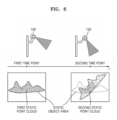
- FIG. 6 is a view for explaining a process of determining the installation abnormality of a sensing device.
- the processor 120 may determine the installation abnormality of the sensing device 100 based on static point clouds having a certain time difference among the static point clouds over time corresponding to a static object area.
- the static object area may be determined from a reference frame of a certain time point at which the sensing device 100 is confirmed to be normally installed.
- the static object area may be determined from a frame of a space information map at a certain time point in the past after the sensing device 100 was normally installed on a structure.
- the processor 120 may extract a first static point cloud at a first time point and a second static point cloud at a second time point having a certain time difference from first time point, from among the static point clouds over time corresponding to the determined static object area.
- the processor 120 may determine whether there is any installation abnormality of the sensing device 100, based on a difference between the first static point cloud and the second static point cloud.
- the processor 120 by executing one or more instructions, may transfer, through the communication interface 140, a result of the determination of the installation abnormality of the sensing device 100 to a server that controls a device or provides a certain service by using the point clouds of the three-dimensional space obtained by the sensing device 100.
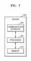
- the server 200 may include a memory 210, a processor 220, and a communication interface 230.
- a memory 210 may be included in addition to the components illustrated in FIG. 7 .
- Other general-purpose components may be included in addition to the components illustrated in FIG. 7 .
- the description of the sensing device 100 presented above may be directly applied to the configuration of the server 200 under the same name, even if the description is omitted below.
- Each component of the block diagram of FIG. 7 may be separated, added, or omitted according to the implementation method of the server 200. In other words, depending on the implementation method, one component may be subdivided into two or more components, two or more components may be combined into one component, or some components may be added or removed.
- the processor 220 may execute the instructions stored in the memory 210.
- the processor 220 may perform the overall control of the server 200.
- the processor 220 may obtain information and requests received through the communication interface 230 and store the received information in a storage (not shown).
- the processor 220 may process the received information.
- the processor 220 may obtain, from the information received from the sensing device 100, information used to control a device or provide a certain service, or perform a processing operation to manage pieces of the received information and store the processed information in the storage.
- the processor 220 may transmit, in response to a request obtained from a manager's terminal, information corresponding to the request to the manager's terminal, through the communication interface 230, by using data or information stored in the storage.
- the communication interface 230 may perform wired/wireless communication with other devices or networks.
- the communication interface 230 may be connected to a device located outside the server 200 to transceive signals or data.
- the server 200 may communicate with the sensing device 100 through the communication interface 230, or may be connected to another server connected via a network.
- the server 200 may obtain the point clouds over time with respect to a three-dimensional space from the sensing device 100 through the communication interface 230, or receive a result of the detection of the installation abnormality of the sensing device 100.
- the server 200 may block or erase the receiving of information or data received from the sensing device 100 where installation abnormality is detected.
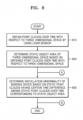
- FIG. 8 is a flowchart for explaining a method of sensing installation abnormality of the sensing device 100, according to an embodiment. Detailed descriptions of the sensing device 100 that are redundant with the descriptions presented above are omitted below.
- the sensing device 100 may obtain point clouds over time with respect to a three-dimensional space by using a LiDAR sensor.
- the sensing device 100 may continuously obtain the point cloud of a three-dimensional space.
- the sensing device 100 may determine a static object area of a three-dimensional space based on the obtained point clouds over time with respect to a three-dimensional space.
- the sensing device 100 may generate a space information map from the obtained point clouds over time with respect to a three-dimensional space.
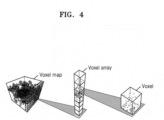
- the space information map may be a normalized map indicating space information, such as a voxel map, a depth map, and the like.
- the sensing device 100 may determine a static object area based on a period during which are continuously detected point clouds in unit areas at corresponding positions between frames of the generated space information map.
- the sensing device 100 may determine a static object area based on a period during which the point clouds in unit areas at corresponding positions between frames of a space information map are continuously detected with the number of points greater than or equal to a minimum detection threshold value.
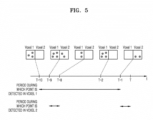
- the sensing device 100 may distinguish, in each frame of the voxel map, a static voxel in which a period during which point clouds in voxels are continuously detected is greater than or equal to a threshold value from a dynamic voxel in which a period during which point clouds in voxels are continuously detected is less than the threshold value, and may determine a static object area formed of static voxels in a reference frame of a specific time point of a voxel map.
- the sensing device 100 may determine a static object area of a three-dimensional space based on a point cloud of an assigned area among the obtained point clouds over time with respect to a three-dimensional space.
- a reference area in which a dynamic point cloud hardly occurs is assigned, instead of using the obtained full point clouds over time with respect to a three-dimensional space, the sensing device 100 may determine a static object area of a three-dimensional space based on a point cloud of the assigned area.
- the reference area may be assigned by a user, or automatically assigned as an area that is determined by the sensing device 100 by using a trained model to be an area of a static point cloud corresponding to a static object corresponding to appropriate height and size.
- the sensing device 100 may determine the installation abnormality of the sensing device 100 based on static point clouds having a certain time difference among the static point clouds over time corresponding to the determined static object area. Operation 830 will be described below in detail with reference to FIG. 9 .
- FIG. 9 is a detailed flowchart for explaining a process of determining the installation abnormality of the sensing device 100. Operation 830 of FIG. 8 described above is described in detail.
- the sensing device 100 may extract a first static point cloud at a first time point and a second static point cloud at a second time point having a certain time difference from the first time point, from among the static point clouds over time corresponding to the determined static object area.
- the sensing device 100 may determine the installation abnormality of the sensing device 100 based on a difference between the first static point cloud and the second static point cloud.
- the sensing device 100 may determine the installation abnormality of the sensing device 100 by comparing a ratio of the number of voxels forming a first static point cloud to the number of all voxels forming the determined static object area with a ratio of the number of voxels forming a second static point cloud to the number of all voxels forming the determined static object area.
- the sensing device 100 may be installed not only on a fixed structure, but also on a moving structure.
- the sensing device 100 when the sensing device 100 is installed on a vehicle or a drone, as a three-dimensional space is changed according to the movement of the vehicle or drone, the position of a static object in the three-dimensional space may be changed in the space information map.
- point clouds of the same space may be obtained based on the position information of the vehicle or drone.
- the above-described embodiments may be implemented in the form of a computer-readable storage medium that stores instructions and data executable by a computer or processor. At least one of the instructions and data may be stored in the form of program code, and when executed by a processor, may generate a certain program module and perform a certain operation.
- the computer-readable storage medium may include read-only memory (ROM), random-access memory (RAM), flash memory, CD-ROMs, CD-Rs, CD+Rs, CD-RWs, CD+RWs, DVD-ROMs, DVD-Rs, DVD+Rs, DVD-RWs, DVD+RWs, DVD-RAMs, BD-ROMs, BD-Rs, BD-R LTHs, BD-REs, magnetic tapes, floppy disks, magneto-optical data storage devices, optical data storage devices, hard disks, solid-state disks (SSDs), and any devices capable of providing instructions or software, associated data, data files, and data structures to a processor or computer so as to execute the instructions.
- ROM read-only memory
- RAM random-access memory
- flash memory CD-ROMs, CD-Rs, CD+Rs, CD-RWs, CD+RWs, DVD-ROMs, DVD-Rs, DVD+Rs, DVD-RWs, DVD+RWs, DVD
Landscapes
- Engineering & Computer Science (AREA)
- Physics & Mathematics (AREA)
- General Physics & Mathematics (AREA)
- Remote Sensing (AREA)
- Computer Networks & Wireless Communication (AREA)
- Radar, Positioning & Navigation (AREA)
- Theoretical Computer Science (AREA)
- Electromagnetism (AREA)
- Multimedia (AREA)
- Computer Vision & Pattern Recognition (AREA)
- Geometry (AREA)
- Software Systems (AREA)
- Computer Graphics (AREA)
- Optical Radar Systems And Details Thereof (AREA)
- Astronomy & Astrophysics (AREA)
- Traffic Control Systems (AREA)
- Measurement Of Optical Distance (AREA)
Applications Claiming Priority (2)
| Application Number | Priority Date | Filing Date | Title |
|---|---|---|---|
| KR1020210113404A KR102656646B1 (ko) | 2021-08-26 | 2021-08-26 | 센싱 장치의 설치 이상을 감지하는 방법 및 이를 수행하는 센싱 장치 |
| PCT/KR2022/012338 WO2023027419A1 (ko) | 2021-08-26 | 2022-08-18 | 센싱 장치의 설치 이상을 감지하는 방법 및 이를 수행하는 센싱 장치 |
Publications (2)
| Publication Number | Publication Date |
|---|---|
| EP4394440A1 true EP4394440A1 (de) | 2024-07-03 |
| EP4394440A4 EP4394440A4 (de) | 2025-10-08 |
Family
ID=85323268
Family Applications (1)
| Application Number | Title | Priority Date | Filing Date |
|---|---|---|---|
| EP22861629.8A Pending EP4394440A4 (de) | 2021-08-26 | 2022-08-18 | Verfahren zur erfassung von installationsanomalien einer erfassungsvorrichtung und erfassungsvorrichtung zur durchführung davon |
Country Status (5)
| Country | Link |
|---|---|
| US (1) | US20240192342A1 (de) |
| EP (1) | EP4394440A4 (de) |
| JP (1) | JP7713624B2 (de) |
| KR (1) | KR102656646B1 (de) |
| WO (1) | WO2023027419A1 (de) |
Families Citing this family (2)
| Publication number | Priority date | Publication date | Assignee | Title |
|---|---|---|---|---|
| JP2023074040A (ja) * | 2021-11-17 | 2023-05-29 | コベルコ建機株式会社 | 監視エリア設定システム |
| DE102023116500A1 (de) * | 2023-06-22 | 2024-12-24 | Intel Corporation | Sensorgestützte objektcharakterisierung als statisch oder dynamisch |
Family Cites Families (20)
| Publication number | Priority date | Publication date | Assignee | Title |
|---|---|---|---|---|
| JP3087606B2 (ja) * | 1995-05-11 | 2000-09-11 | 株式会社日立製作所 | 自動車用車間距離計測装置及び方法 |
| JP5716902B2 (ja) * | 2011-03-09 | 2015-05-13 | 株式会社Ihi | 監視方法及び監視装置 |
| US9110163B2 (en) * | 2013-06-14 | 2015-08-18 | Microsoft Technology Licensing, Llc | Lidar-based classification of object movement |
| US9430822B2 (en) * | 2013-06-14 | 2016-08-30 | Microsoft Technology Licensing, Llc | Mobile imaging platform calibration |
| DE102015205087A1 (de) * | 2015-03-20 | 2016-09-22 | Bayerische Motoren Werke Aktiengesellschaft | Verfahren zum Ermitteln der Dejustage eines Fahrersassistenzsensors |
| CN105184852B (zh) * | 2015-08-04 | 2018-01-30 | 百度在线网络技术(北京)有限公司 | 一种基于激光点云的城市道路识别方法及装置 |
| CN108780154B (zh) * | 2016-03-14 | 2023-06-09 | 亿目朗欧洲股份有限公司 | 3d点云的处理方法 |
| CN107976688A (zh) * | 2016-10-25 | 2018-05-01 | 菜鸟智能物流控股有限公司 | 一种障碍物的检测方法及相关装置 |
| US10444759B2 (en) * | 2017-06-14 | 2019-10-15 | Zoox, Inc. | Voxel based ground plane estimation and object segmentation |
| US11796657B2 (en) * | 2017-10-26 | 2023-10-24 | Pioneer Corporation | Control device, control method, program, and storage medium |
| JP2019144210A (ja) * | 2018-02-23 | 2019-08-29 | コニカミノルタ株式会社 | 物体検出システム |
| US10830871B2 (en) * | 2018-03-21 | 2020-11-10 | Zoox, Inc. | Sensor calibration |
| US11995763B2 (en) * | 2018-07-02 | 2024-05-28 | Vayyar Imaging Ltd. | System and methods for environment mapping |
| KR102647928B1 (ko) * | 2018-11-16 | 2024-03-15 | 현대모비스 주식회사 | 객체 검출 센서의 장착 오차 판단 장치 및 방법 |
| CN111238494B (zh) * | 2018-11-29 | 2022-07-19 | 财团法人工业技术研究院 | 载具、载具定位系统及载具定位方法 |
| KR102140973B1 (ko) * | 2019-03-27 | 2020-09-14 | 주식회사 이에스피 | LiDAR를 이용한 광산 갱내 붕괴 감시 시스템 |
| CN112444283B (zh) * | 2019-09-02 | 2023-12-05 | 华晨宝马汽车有限公司 | 车辆组合件的检测设备和车辆组合件生产系统 |
| KR102238522B1 (ko) * | 2019-09-27 | 2021-04-09 | 주식회사 서울로보틱스 | 3차원 공간에 대응되는 맵을 생성하는 차량 및 방법 |
| DE102019132150A1 (de) * | 2019-11-27 | 2021-05-27 | Bayerische Motoren Werke Aktiengesellschaft | Verfahren zum automatischen Kalibrieren eines Umfeldsensors, insbesondere eines Lidar-Sensors, eines Fahrzeugs auf Grundlage von Belegungskarten sowie Recheneinrichtung |
| KR20210103172A (ko) * | 2020-02-13 | 2021-08-23 | 공주대학교 산학협력단 | 방범 경비 시스템 |
-
2021
- 2021-08-26 KR KR1020210113404A patent/KR102656646B1/ko active Active
-
2022
- 2022-08-18 WO PCT/KR2022/012338 patent/WO2023027419A1/ko not_active Ceased
- 2022-08-18 JP JP2024512021A patent/JP7713624B2/ja active Active
- 2022-08-18 EP EP22861629.8A patent/EP4394440A4/de active Pending
-
2024
- 2024-02-23 US US18/585,611 patent/US20240192342A1/en active Pending
Also Published As
| Publication number | Publication date |
|---|---|
| WO2023027419A1 (ko) | 2023-03-02 |
| KR102656646B1 (ko) | 2024-04-12 |
| JP2024537934A (ja) | 2024-10-17 |
| US20240192342A1 (en) | 2024-06-13 |
| EP4394440A4 (de) | 2025-10-08 |
| JP7713624B2 (ja) | 2025-07-28 |
| KR20230031035A (ko) | 2023-03-07 |
Similar Documents
| Publication | Publication Date | Title |
|---|---|---|
| KR102453933B1 (ko) | 3차원 공간을 추적하는 차량 및 센싱 장치, 그리고 저장매체에 저장된 컴퓨터 프로그램 | |
| US12062286B2 (en) | Method, apparatus, server, and computer program for collision accident prevention | |
| US20240192342A1 (en) | Method for sensing installation abnormality of sensing device, and sensing device for performing same | |
| US20240192366A1 (en) | Method and sensing device for monitoring region of interest in workspace | |
| US11507101B2 (en) | Vehicle using spatial information acquired using sensor, sensing device using spatial information acquired using sensor, and server | |
| CN110471086A (zh) | 一种雷达测障系统及方法 | |
| US20240193898A1 (en) | Method and server for matching point groups in three-dimensional space | |
| KR102255924B1 (ko) | 레인을 검출하는 차량 및 방법 | |
| CN115244362B (zh) | 用于生成环境的数字地图的系统、方法和计算机程序 | |
| WO2019188429A1 (ja) | 動体管理装置、動体管理システム、動体管理方法、及びコンピュータプログラム | |
| KR20230031038A (ko) | 3차원 공간의 관심 영역을 모니터링하는 방법 및 센싱 장치 | |
| JP2021093146A (ja) | 転倒検知及び支援 | |
| US20250371726A1 (en) | Electronic device, control method, and control program | |
| US20230408686A1 (en) | Method and apparatus for detecting static object by means of radar sensor of roadside unit | |
| KR20230105967A (ko) | 작업 현장을 모니터링하는 방법 및 장치 | |
| JP5604893B2 (ja) | 目標物管理装置および目標物管理方法 | |
| KR102587926B1 (ko) | 객체 추적 장치, 객체 추적 방법 및 이를 수행하는 프로그램을 기록한 기록매체 | |
| US20250378565A1 (en) | Electronic device, control method, and control program | |
| JP2024053390A (ja) | 位置分析システム | |
| CN118424304A (zh) | 一种地图构建的回环检测方法、电子设备及存储介质 | |
| CN115876209A (zh) | 地图构建方法、地图构建装置、配送机器人及存储介质 | |
| HK40022826A (en) | Method and system for close loop perception in autonomous driving vehicles |
Legal Events
| Date | Code | Title | Description |
|---|---|---|---|
| STAA | Information on the status of an ep patent application or granted ep patent |
Free format text: STATUS: THE INTERNATIONAL PUBLICATION HAS BEEN MADE |
|
| PUAI | Public reference made under article 153(3) epc to a published international application that has entered the european phase |
Free format text: ORIGINAL CODE: 0009012 |
|
| STAA | Information on the status of an ep patent application or granted ep patent |
Free format text: STATUS: REQUEST FOR EXAMINATION WAS MADE |
|
| 17P | Request for examination filed |
Effective date: 20240221 |
|
| AK | Designated contracting states |
Kind code of ref document: A1 Designated state(s): AL AT BE BG CH CY CZ DE DK EE ES FI FR GB GR HR HU IE IS IT LI LT LU LV MC MK MT NL NO PL PT RO RS SE SI SK SM TR |
|
| DAV | Request for validation of the european patent (deleted) | ||
| DAX | Request for extension of the european patent (deleted) | ||
| A4 | Supplementary search report drawn up and despatched |
Effective date: 20250910 |
|
| RIC1 | Information provided on ipc code assigned before grant |
Ipc: G01S 7/497 20060101AFI20250904BHEP Ipc: G01S 17/894 20200101ALI20250904BHEP Ipc: G06T 7/11 20170101ALI20250904BHEP Ipc: G06T 17/05 20110101ALI20250904BHEP Ipc: G06V 20/13 20220101ALI20250904BHEP Ipc: G01S 7/48 20060101ALI20250904BHEP Ipc: G01S 17/89 20200101ALI20250904BHEP Ipc: G01S 17/931 20200101ALI20250904BHEP Ipc: G01S 17/42 20060101ALI20250904BHEP Ipc: G06V 10/62 20220101ALI20250904BHEP Ipc: G06V 20/52 20220101ALI20250904BHEP Ipc: G06V 20/64 20220101ALI20250904BHEP Ipc: G06T 7/73 20170101ALI20250904BHEP |