EP4394367A1 - Elektronenspinresonanzvorrichtung und verfahren zur beurteilung der verschlechterung - Google Patents
Elektronenspinresonanzvorrichtung und verfahren zur beurteilung der verschlechterung Download PDFInfo
- Publication number
- EP4394367A1 EP4394367A1 EP22917655.7A EP22917655A EP4394367A1 EP 4394367 A1 EP4394367 A1 EP 4394367A1 EP 22917655 A EP22917655 A EP 22917655A EP 4394367 A1 EP4394367 A1 EP 4394367A1
- Authority
- EP
- European Patent Office
- Prior art keywords
- measurement target
- load
- microwave
- electron spin
- spins
- Prior art date
- Legal status (The legal status is an assumption and is not a legal conclusion. Google has not performed a legal analysis and makes no representation as to the accuracy of the status listed.)
- Pending
Links
Images



Classifications
-
- G—PHYSICS
- G01—MEASURING; TESTING
- G01R—MEASURING ELECTRIC VARIABLES; MEASURING MAGNETIC VARIABLES
- G01R33/00—Arrangements or instruments for measuring magnetic variables
- G01R33/20—Arrangements or instruments for measuring magnetic variables involving magnetic resonance
- G01R33/60—Arrangements or instruments for measuring magnetic variables involving magnetic resonance using electron paramagnetic resonance
-
- G—PHYSICS
- G01—MEASURING; TESTING
- G01N—INVESTIGATING OR ANALYSING MATERIALS BY DETERMINING THEIR CHEMICAL OR PHYSICAL PROPERTIES
- G01N22/00—Investigating or analysing materials by the use of microwaves or radio waves, i.e. electromagnetic waves with a wavelength of one millimetre or more
- G01N22/02—Investigating the presence of flaws
-
- G—PHYSICS
- G01—MEASURING; TESTING
- G01N—INVESTIGATING OR ANALYSING MATERIALS BY DETERMINING THEIR CHEMICAL OR PHYSICAL PROPERTIES
- G01N24/00—Investigating or analyzing materials by the use of nuclear magnetic resonance, electron paramagnetic resonance or other spin effects
- G01N24/08—Investigating or analyzing materials by the use of nuclear magnetic resonance, electron paramagnetic resonance or other spin effects by using nuclear magnetic resonance
-
- G—PHYSICS
- G01—MEASURING; TESTING
- G01N—INVESTIGATING OR ANALYSING MATERIALS BY DETERMINING THEIR CHEMICAL OR PHYSICAL PROPERTIES
- G01N24/00—Investigating or analyzing materials by the use of nuclear magnetic resonance, electron paramagnetic resonance or other spin effects
- G01N24/10—Investigating or analyzing materials by the use of nuclear magnetic resonance, electron paramagnetic resonance or other spin effects by using electron paramagnetic resonance
-
- G—PHYSICS
- G01—MEASURING; TESTING
- G01R—MEASURING ELECTRIC VARIABLES; MEASURING MAGNETIC VARIABLES
- G01R33/00—Arrangements or instruments for measuring magnetic variables
- G01R33/20—Arrangements or instruments for measuring magnetic variables involving magnetic resonance
- G01R33/28—Details of apparatus provided for in groups G01R33/44 - G01R33/64
- G01R33/32—Excitation or detection systems, e.g. using radio frequency signals
Definitions
- Patent Document 2 discloses an electron spin resonance device that sweeps the frequency of a microwave while applying a constant magnetic field with a permanent magnet.
- the present disclosure provides the following.
- the electron spin resonance device 10 includes, for example, a microwave oscillator 11, a magnet 12, a modulation coil 13, and a cavity resonator 14.
- the electron spin resonance device 10 is connected to a power supply 15 and a detection device 16 at the time of use.
- the detection device 16 includes a detector 16A, an amplifier 16B, and a calculator 16C.
- the detector 16A detects an electron spin resonance (ESR) signal.
- the detector 16A is, for example, a crystal diode detector.
- the amplifier 16B amplifies an electron spin resonance signal.
- the calculator 16C is, for example, a computer.
- the calculator 16C is used to analyze the electron spin resonance signal.
- the calculator 16C has, for example, a recording area in which the detected data is recorded and a signal processing area in which the detected data is analyzed.
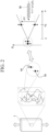
- FIG. 2 is a conceptual diagram showing the measurement principle of the electron spin resonance device 10 according to the first embodiment.
- the state of the measurement target 1 changes.
- a load for example, intermolecular force between polymer chains changes, polymer chains are cut, cross-linked structures are broken, or stress applied to the inter-fiber interface bond changes.
- a polymer chain for example, a radical is generated at the cut surface and thus a spin sp (unpaired electron) is generated in the measurement target 1.
- the spin sp is split into a ⁇ spin parallel to the magnetic field and an ⁇ spin antiparallel to the magnetic field due to the Zeeman effect in the magnetic field.
- the energy difference between the ⁇ spin and the ⁇ spin increases in proportion to the magnetic field intensity.
- the electron spin absorbs the microwave M and transitions to the upper state.
- the electron spin resonance signal is observed at the time of this transition in state.
- the electron spin resonance signal is, for example, an absorption spectrum of the microwave M.
- the electron spin resonance device 10 evaluates the state of the measurement target 1 by this procedure.
- the measurement principle of the electron spin resonance device 10 has been described using case where the microwave M is fixed and the magnetic field intensity is swept by way of example, but the magnetic field intensity may be fixed and the frequency of the microwave M may be swept.
- the measurement target 1 may have a high concentration spin.
- the measurement target 1 includes 10 11 spins/g or more in a permeation region 2 in which the microwave M is irradiated and which the microwave permeates.
- the measurement target 1 preferably includes 10 15 spins/g or more, more preferably includes 10 17 spins/g or more, and further preferably includes 10 20 spins/g or more in the permeation region 2.
- the electron spin resonance device 10 is not required to have high sensitivity.
- the electron spin resonance device 10 according to the present embodiment can be reduced in size and simplified in configuration.
- the permeation region 2 is a range in which the microwave M can permeate.
- the permeation region 2 is represented by the product of "an area irradiated with the microwave M" and "a permeation depth of the microwave M".
- the region irradiated with the microwave M is a region facing the opening 14B.
- the area of the measurement target 1 irradiated with the microwave M substantially matches the area of the opening 14B.
- the area irradiated with the microwave M matches the area of the irradiation surface.
- the permeation depth of the microwave M in the measurement target 1 is, for example, about 1cm. That is, the permeation region 2 is, for example, a region of about 10 cm 3 .
- the measurement target 1 is, for example, a carbon fiber composite material.
- the carbon fiber composite material is, for example, carbon fiber reinforced plastic (CFRP) or carbon fiber reinforced thermoplastic (CFRTP).
- CFRP is a reinforced plastic in which carbon fibers are used as a reinforcing material and a thermosetting resin is used as a base material.
- CFRTP is a reinforced plastic in which carbon fibers are used as a reinforcing material and a thermoplastic resin is used as a base material.
- internal stress is likely to occur at the time of manufacturing due to a difference in thermal shrinkage between the carbon fibers and the resin. Therefore, the carbon fiber composite material has a high concentration spin even in a no-load state before applying a load.
- Carbon fiber composite materials are used in airplanes, automobiles, and the like.
- the electron spin resonance device 10 is small, lightweight, and portable. Additionally, since the electron spin resonance device 10 applies the magnetic field H and the microwave M in the same direction, the measurement target 1 does not need to be sandwiched by generation sources of the magnetic field H and the microwave M. Accordingly, the size and shape of the measurement target 1 are not limited and a measurement target 1 having any shape can be measured. For example, even when the measurement target 1 is an airplane or the like, the state of the measurement target 1 can be evaluated by orienting the opening 14B of the electron spin resonance device 10 toward the measuring location.
- FIG. 3 is a first flowchart of the deterioration evaluation method according to the first embodiment.
- the deterioration evaluation method includes a preparation step S1, a detection step S2, and an evaluation step S3.
- the preparation step S1 is performed in advance before evaluating the actual measurement target 1.
- the actual measurement target 1 is measured in the detection step S2 and the evaluation step S3.
- the preparation step S1 includes a reference specimen preparation step S11, a reference specimen measurement step S12, a load application step S13, a service life measurement step S14, and a critical value calculation step S15.
- the preparation step S1 is performed before the detection step S2.
- a reference specimen having the same configuration as the measurement target 1 is used to find, in advance, the relationship between the deterioration of the reference specimen and the electron spin resonance signal (ESR signal) of the reference specimen.
- ESR signal electron spin resonance signal
- the reference specimen is prepared.
- the reference specimen is made of a substance similar to that of the measurement target 1.
- the reference specimen is a specimen produced under the same conditions as the measurement target 1.
- the reference specimen is, for example, a carbon fiber composite material.
- the size of the reference specimen does not need to be the same as that of the measurement target 1, and may be any size.
- the reference specimen measurement step S12 an electron spin resonance analysis is performed on the reference specimen.
- the reference specimen measurement step S 12 is performed before applying a load to the reference specimen and is performed each time the load is applied a predetermined number of times.
- the reference specimen measurement step S12 may be performed using, for example, the above-described electron spin resonance device 10 or a known electron spin resonance device. Since the size of the reference specimen is not limited, the measurement can be performed using a known electron spin resonance device, in which a specimen is put into a cavity in which microwaves resonate.
- a load is applied to the reference specimen.
- the reference specimen is stretched in one direction.
- the load is applied to the reference specimen a plurality of times.
- the reference specimen measurement step S12 is performed every certain number of load applications.
- the critical value calculation step S 15 at least one of the standardized number of spins at the time when delamination occurs and the standardized number of spins at the time when complete breakage occurs is found.
- N max the number of load applications until breakage
- N' spin (N max ) the number of spins in the reference specimen at that time
- the value obtained by dividing N' spin (N max ) by N' spin (0) is the standardized number of spins at the time when breakage occurs, and is hereinafter referred to as a critical value.
- N' spin (0) is the number of spins in the reference specimen before load application.
- the critical value represents how many times the number of spins increased from the initial state in which the load is applied until the breakage occurs. As an example, delamination may occur when the critical value is 1.85 (the number of spins is 1.85 times), and complete breakage may occur when the critical value is about 2.0 times (the number of spins is about 2 times).
- the detection step S2 includes an actual measurement step S21 of actually measuring the measurement target 1 and a load application step S22 of applying a load to the measurement target 1.
- the actual measurement step S21 may be performed before applying the load to the measurement target 1 and each time the load is applied a predetermined number of times.
- the actual measurement step S21 is performed using, for example, the electron spin resonance device 10 described above.
- the microwave M and the magnetic field H are applied to the measurement target 1, and the electron spin resonance signal of the measurement target 1 is detected by electron spin resonance.
- the microwave M is reflected by the measurement target 1 and detected by the detector 16A of the detection device 16. At the magnetic field intensity at a predetermined time, the microwave M is absorbed by the measurement target 1, and thus an absorption spectrum of the microwave M is obtained.
- Equation (1) A is a constant.
- FIG. 4 is a second flowchart of the deterioration evaluation method according to the first embodiment.
- the deterioration evaluation method based on the second flowchart includes a preparation step S1', a detection step S2', and an evaluation step S3'.
- the preparation step S1' is a preparation step performed in advance before the actual measurement target 1 is evaluated.
- the detection step S2' and the evaluation step S3' are actual measurement steps for measuring the actual measurement target 1.
- the preparation step S1' includes a reference specimen preparation step S11, a reference specimen measurement step S12, a load application step S13, a service life measurement step S14, and an analyzing step S16.
- the reference specimen preparation step S11, the reference specimen measurement step S12, the load application step S13, and the service life measurement step S14 are the same as those in the first flow.
- the evaluation step S3' the data detected in the detection step S2' is analyzed, and the deterioration of the measurement target 1 is evaluated from the detected number of spins in the measurement target 1.
- the evaluation step S3' is performed, for example, by the calculator 16C of the detection device 16.
- the evaluation step S3' includes an estimation step S34 for the number of load applications and a service life estimation step S35.
- the method using the first flow is highly reliable since fitting is performed using actual measurement values. Since the method using the second flow requires only one measurement of the measurement target 1, this method is suitable for a measurement target having an unknown state.
- the electron spin resonance device 10 according to the present embodiment limits the measurement target 1, a high Q value is not required, and thus the size can be reduced and the configuration can be simplified.
- the electron spin resonance device 10 according to the present embodiment applies the magnetic field H and the microwave M toward the measurement target 1 from one direction, measurement can be performed regardless of the shape or size of the measurement target 1.
- the arrangement of the plurality of units U1 is not particularly limited.
- the plurality of units U1 are arranged in, for example, a line or an array.
- the plurality of units U1 are connected to, for example, one power supply 15.
- a high frequency wave generated by the power supply 15 is branched by wiring and propagated to each microwave oscillator 11.
- FIG. 6 is a schematic perspective view of an electron spin resonance device 10B according to a second modification.
- the electron spin resonance device 10B includes a plurality of units U2.
- Each of the plurality of units U2 includes a microwave oscillator 11, a magnet 12, a modulation coil 13, and a cavity resonator 14.
- the microwave oscillator 11, the magnet 12, the modulation coil 13, and the cavity resonator 14 are the same as those described above.
- Some of the units U2 of the plurality of units U2 share at least one of the microwave oscillator 11, the magnet 12, or the modulation coil 13 with other units U2.
- FIG. 6 illustrates an example in which the magnet 12 is shared by the plurality of units U2. In this case, the magnets 12 of the adjacent units U2 are integrated.
- the electron spin resonance device 10B according to the first modification includes the plurality of units U2, measurement of a large area can be performed at one time. In addition, handling is easy because the units U2 are connected to each other.
- FIG. 8 shows the measurement results of the first experimental example. A difference was barely observed in the intensity of the ESR signal, the g-factor, and the ESR line width of sample 1, sample 2, and sample 3.
- the carbon fiber composite material shows that the number of spins contained in the initial state is sufficiently larger than the number of spins generated at the cut surface by cutting or the like. That is, evaluation can be performed regardless of the processing size, and evaluation of the measurement target 1 can be performed based on the reference specimen.
Landscapes
- Physics & Mathematics (AREA)
- General Physics & Mathematics (AREA)
- Biochemistry (AREA)
- Life Sciences & Earth Sciences (AREA)
- Chemical & Material Sciences (AREA)
- Analytical Chemistry (AREA)
- Health & Medical Sciences (AREA)
- General Health & Medical Sciences (AREA)
- Immunology (AREA)
- Pathology (AREA)
- Condensed Matter Physics & Semiconductors (AREA)
- High Energy & Nuclear Physics (AREA)
- Electromagnetism (AREA)
- Analysing Materials By The Use Of Radiation (AREA)
- Measuring Magnetic Variables (AREA)
Applications Claiming Priority (2)
| Application Number | Priority Date | Filing Date | Title |
|---|---|---|---|
| JP2022001004 | 2022-01-06 | ||
| PCT/JP2022/043495 WO2023132149A1 (ja) | 2022-01-06 | 2022-11-25 | 電子スピン共鳴装置及び劣化評価方法 |
Publications (2)
| Publication Number | Publication Date |
|---|---|
| EP4394367A1 true EP4394367A1 (de) | 2024-07-03 |
| EP4394367A4 EP4394367A4 (de) | 2025-11-19 |
Family
ID=87073414
Family Applications (1)
| Application Number | Title | Priority Date | Filing Date |
|---|---|---|---|
| EP22917655.7A Pending EP4394367A4 (de) | 2022-01-06 | 2022-11-25 | Elektronenspinresonanzvorrichtung und verfahren zur beurteilung der verschlechterung |
Country Status (6)
| Country | Link |
|---|---|
| US (1) | US20240393418A1 (de) |
| EP (1) | EP4394367A4 (de) |
| JP (1) | JP7853718B2 (de) |
| KR (1) | KR20240046266A (de) |
| CN (1) | CN118056128A (de) |
| WO (1) | WO2023132149A1 (de) |
Family Cites Families (5)
| Publication number | Priority date | Publication date | Assignee | Title |
|---|---|---|---|---|
| WO2005111645A2 (en) * | 2004-05-07 | 2005-11-24 | Regents Of The University Of Minnesota | Multi-current elements for magnetic resonance radio frequency coils |
| AR070754A1 (es) * | 2007-09-18 | 2010-05-05 | Medichem Sa | Proceso mejorado para preparar clorhidrato de cinacalcet |
| JP5481651B2 (ja) | 2010-07-20 | 2014-04-23 | 公一 中川 | 電子スピン共鳴装置 |
| JP5973397B2 (ja) | 2013-08-30 | 2016-08-23 | 日本電信電話株式会社 | 電子スピン共鳴装置 |
| JP7393306B2 (ja) | 2020-06-19 | 2023-12-06 | 矢崎総業株式会社 | 電線保護チューブの装着方法および電線保護チューブ供給装置 |
-
2022
- 2022-11-25 JP JP2023572372A patent/JP7853718B2/ja active Active
- 2022-11-25 WO PCT/JP2022/043495 patent/WO2023132149A1/ja not_active Ceased
- 2022-11-25 CN CN202280066390.5A patent/CN118056128A/zh active Pending
- 2022-11-25 KR KR1020247009462A patent/KR20240046266A/ko active Pending
- 2022-11-25 US US18/696,741 patent/US20240393418A1/en active Pending
- 2022-11-25 EP EP22917655.7A patent/EP4394367A4/de active Pending
Also Published As
| Publication number | Publication date |
|---|---|
| WO2023132149A1 (ja) | 2023-07-13 |
| US20240393418A1 (en) | 2024-11-28 |
| JPWO2023132149A1 (de) | 2023-07-13 |
| JP7853718B2 (ja) | 2026-04-30 |
| CN118056128A (zh) | 2024-05-17 |
| EP4394367A4 (de) | 2025-11-19 |
| KR20240046266A (ko) | 2024-04-08 |
Similar Documents
| Publication | Publication Date | Title |
|---|---|---|
| CA2167119C (en) | Detection and sorting of materials | |
| GB2489005A (en) | Examination of porosity by NMR and intrusion porosimetry | |
| JP2015004677A5 (de) | ||
| CN1914500A (zh) | 用于芯片上磁共振波谱分析的方法和器件 | |
| US7034550B2 (en) | Ferromagnetic resonance measurement | |
| EP4394367A1 (de) | Elektronenspinresonanzvorrichtung und verfahren zur beurteilung der verschlechterung | |
| Venâncio et al. | Simultaneous measurements of T1 and T2 during fast polymerization reaction using continuous wave‐free precession NMR method | |
| US7176681B2 (en) | Inspection of composite components using magnetic resonance imaging | |
| Bevington et al. | Magnetic induction tomography of structural defects with alkali–metal spin maser | |
| Pagliero et al. | Time-resolved, optically detected NMR of fluids at high magnetic field | |
| US5030914A (en) | Electron paramagnetic resonance instrument with superconductive cavity | |
| RU2654967C1 (ru) | Способ измерения характеристик магнитного поля | |
| Guo et al. | An optimized UMR sensor for non-destructive measurements of moisture in wood | |
| Nandini et al. | Dielectric property investigation of degraded pre-preg and performance prediction of the final composite part | |
| Tarpani et al. | Magnetic resonance imaging of contaminated and damaged core cells in polymer composite sandwich panels | |
| Kawabata et al. | Power spectral density imaging for polymeric films using ex-situ solid-state magnetic resonance with needlelike ferromagnet | |
| RU2358261C1 (ru) | Свч-способ определения влажности органических веществ | |
| Shi et al. | Self-diffusion coefficient of bound water in longleaf pine wood investigated with pulsed-field-gradient 1H-NMR and molecular simulation | |
| Noohi et al. | Portable Nuclear Magnetic Resonance Spectrometer with Birdcage Coil for Non-destructive Testing and Analysis of Metallic Materials | |
| Matytsin et al. | Permittivity measurement using slotted coaxial resonator | |
| Parnell et al. | Measurement of laser heating in spin exchange optical pumping by NMR diffusion sensitization gradients | |
| Kawabata et al. | Static-gradient NMR imaging for depth-resolved molecular diffusion in amorphous regions in semicrystalline poly (tetrafluoroethylene) film | |
| JPWO2023132149A5 (de) | ||
| Ito et al. | Development of simultaneous detection method of millimeter-wave ESR and EDMR signals of phosphorous-doped silicon | |
| Zhou et al. | Nondestructive Testing of Epoxy Resin Subjected to Multi-Factor Aging using Terahertz Waves |
Legal Events
| Date | Code | Title | Description |
|---|---|---|---|
| STAA | Information on the status of an ep patent application or granted ep patent |
Free format text: STATUS: THE INTERNATIONAL PUBLICATION HAS BEEN MADE |
|
| PUAI | Public reference made under article 153(3) epc to a published international application that has entered the european phase |
Free format text: ORIGINAL CODE: 0009012 |
|
| STAA | Information on the status of an ep patent application or granted ep patent |
Free format text: STATUS: REQUEST FOR EXAMINATION WAS MADE |
|
| 17P | Request for examination filed |
Effective date: 20240327 |
|
| AK | Designated contracting states |
Kind code of ref document: A1 Designated state(s): AL AT BE BG CH CY CZ DE DK EE ES FI FR GB GR HR HU IE IS IT LI LT LU LV MC ME MK MT NL NO PL PT RO RS SE SI SK SM TR |
|
| DAV | Request for validation of the european patent (deleted) | ||
| DAX | Request for extension of the european patent (deleted) | ||
| RIC1 | Information provided on ipc code assigned before grant |
Ipc: G01N 24/10 20060101AFI20250723BHEP Ipc: G01N 22/02 20060101ALI20250723BHEP Ipc: G01R 33/32 20060101ALI20250723BHEP Ipc: G01R 33/60 20060101ALI20250723BHEP |
|
| A4 | Supplementary search report drawn up and despatched |
Effective date: 20251020 |
|
| RIC1 | Information provided on ipc code assigned before grant |
Ipc: G01N 24/10 20060101AFI20251014BHEP Ipc: G01N 22/02 20060101ALI20251014BHEP Ipc: G01R 33/32 20060101ALI20251014BHEP Ipc: G01R 33/60 20060101ALI20251014BHEP Ipc: G01N 24/08 20060101ALI20251014BHEP |