EP4394355A1 - Dispositif de mesure, procédé de mesure et programme - Google Patents
Dispositif de mesure, procédé de mesure et programme Download PDFInfo
- Publication number
- EP4394355A1 EP4394355A1 EP22861169.5A EP22861169A EP4394355A1 EP 4394355 A1 EP4394355 A1 EP 4394355A1 EP 22861169 A EP22861169 A EP 22861169A EP 4394355 A1 EP4394355 A1 EP 4394355A1
- Authority
- EP
- European Patent Office
- Prior art keywords
- light
- unit
- vision sensor
- measurement
- measurement device
- Prior art date
- Legal status (The legal status is an assumption and is not a legal conclusion. Google has not performed a legal analysis and makes no representation as to the accuracy of the status listed.)
- Pending
Links
- 238000000034 method Methods 0.000 title description 14
- 238000005259 measurement Methods 0.000 claims abstract description 265
- 238000003384 imaging method Methods 0.000 claims abstract description 158
- 238000005286 illumination Methods 0.000 claims abstract description 129
- 238000012545 processing Methods 0.000 claims description 66
- 239000002245 particle Substances 0.000 claims description 63
- 230000033001 locomotion Effects 0.000 claims description 36
- 238000006243 chemical reaction Methods 0.000 claims description 28
- 230000007246 mechanism Effects 0.000 claims description 13
- 238000000691 measurement method Methods 0.000 claims description 6
- 238000010586 diagram Methods 0.000 description 41
- 238000005516 engineering process Methods 0.000 description 25
- 238000012986 modification Methods 0.000 description 20
- 230000004048 modification Effects 0.000 description 20
- XLYOFNOQVPJJNP-UHFFFAOYSA-N water Substances O XLYOFNOQVPJJNP-UHFFFAOYSA-N 0.000 description 20
- 244000005700 microbiome Species 0.000 description 16
- 238000010801 machine learning Methods 0.000 description 13
- 238000004891 communication Methods 0.000 description 8
- 230000005484 gravity Effects 0.000 description 8
- 238000011835 investigation Methods 0.000 description 8
- 230000005284 excitation Effects 0.000 description 7
- 238000012549 training Methods 0.000 description 7
- 239000003086 colorant Substances 0.000 description 6
- 230000009087 cell motility Effects 0.000 description 5
- OKTJSMMVPCPJKN-UHFFFAOYSA-N Carbon Chemical compound [C] OKTJSMMVPCPJKN-UHFFFAOYSA-N 0.000 description 4
- CURLTUGMZLYLDI-UHFFFAOYSA-N Carbon dioxide Chemical compound O=C=O CURLTUGMZLYLDI-UHFFFAOYSA-N 0.000 description 4
- 229910052799 carbon Inorganic materials 0.000 description 4
- 238000001514 detection method Methods 0.000 description 4
- 230000000694 effects Effects 0.000 description 4
- 239000010410 layer Substances 0.000 description 4
- VNWKTOKETHGBQD-UHFFFAOYSA-N methane Chemical compound C VNWKTOKETHGBQD-UHFFFAOYSA-N 0.000 description 4
- 230000003287 optical effect Effects 0.000 description 4
- 239000000779 smoke Substances 0.000 description 4
- 229920000426 Microplastic Polymers 0.000 description 3
- 230000007613 environmental effect Effects 0.000 description 3
- 239000013535 sea water Substances 0.000 description 3
- XEEYBQQBJWHFJM-UHFFFAOYSA-N Iron Chemical compound [Fe] XEEYBQQBJWHFJM-UHFFFAOYSA-N 0.000 description 2
- 238000009360 aquaculture Methods 0.000 description 2
- 244000144974 aquaculture Species 0.000 description 2
- 238000013528 artificial neural network Methods 0.000 description 2
- 229910002092 carbon dioxide Inorganic materials 0.000 description 2
- 239000001569 carbon dioxide Substances 0.000 description 2
- 238000013135 deep learning Methods 0.000 description 2
- 238000007599 discharging Methods 0.000 description 2
- 238000010191 image analysis Methods 0.000 description 2
- 238000011176 pooling Methods 0.000 description 2
- 230000009467 reduction Effects 0.000 description 2
- 239000004065 semiconductor Substances 0.000 description 2
- RWSOTUBLDIXVET-UHFFFAOYSA-N Dihydrogen sulfide Chemical compound S RWSOTUBLDIXVET-UHFFFAOYSA-N 0.000 description 1
- 230000001133 acceleration Effects 0.000 description 1
- 230000006399 behavior Effects 0.000 description 1
- 230000005540 biological transmission Effects 0.000 description 1
- 230000008859 change Effects 0.000 description 1
- 230000000295 complement effect Effects 0.000 description 1
- 238000011161 development Methods 0.000 description 1
- 239000000284 extract Substances 0.000 description 1
- 230000006870 function Effects 0.000 description 1
- 239000007789 gas Substances 0.000 description 1
- 229910001385 heavy metal Inorganic materials 0.000 description 1
- 229910052734 helium Inorganic materials 0.000 description 1
- 239000001307 helium Substances 0.000 description 1
- SWQJXJOGLNCZEY-UHFFFAOYSA-N helium atom Chemical compound [He] SWQJXJOGLNCZEY-UHFFFAOYSA-N 0.000 description 1
- 239000001257 hydrogen Substances 0.000 description 1
- 229910052739 hydrogen Inorganic materials 0.000 description 1
- 125000004435 hydrogen atom Chemical class [H]* 0.000 description 1
- 229910000037 hydrogen sulfide Inorganic materials 0.000 description 1
- 229910052742 iron Inorganic materials 0.000 description 1
- 230000001678 irradiating effect Effects 0.000 description 1
- WPBNNNQJVZRUHP-UHFFFAOYSA-L manganese(2+);methyl n-[[2-(methoxycarbonylcarbamothioylamino)phenyl]carbamothioyl]carbamate;n-[2-(sulfidocarbothioylamino)ethyl]carbamodithioate Chemical compound [Mn+2].[S-]C(=S)NCCNC([S-])=S.COC(=O)NC(=S)NC1=CC=CC=C1NC(=S)NC(=O)OC WPBNNNQJVZRUHP-UHFFFAOYSA-L 0.000 description 1
- 229910052751 metal Inorganic materials 0.000 description 1
- 239000002184 metal Substances 0.000 description 1
- 150000002739 metals Chemical class 0.000 description 1
- 239000003345 natural gas Substances 0.000 description 1
- 230000004044 response Effects 0.000 description 1
- 239000013049 sediment Substances 0.000 description 1
- 239000000126 substance Substances 0.000 description 1
- 239000002344 surface layer Substances 0.000 description 1
- 230000001360 synchronised effect Effects 0.000 description 1
- 238000010792 warming Methods 0.000 description 1
Images


Classifications
-
- G—PHYSICS
- G01—MEASURING; TESTING
- G01N—INVESTIGATING OR ANALYSING MATERIALS BY DETERMINING THEIR CHEMICAL OR PHYSICAL PROPERTIES
- G01N21/00—Investigating or analysing materials by the use of optical means, i.e. using sub-millimetre waves, infrared, visible or ultraviolet light
- G01N21/17—Systems in which incident light is modified in accordance with the properties of the material investigated
- G01N21/25—Colour; Spectral properties, i.e. comparison of effect of material on the light at two or more different wavelengths or wavelength bands
- G01N21/27—Colour; Spectral properties, i.e. comparison of effect of material on the light at two or more different wavelengths or wavelength bands using photo-electric detection ; circuits for computing concentration
-
- G—PHYSICS
- G01—MEASURING; TESTING
- G01N—INVESTIGATING OR ANALYSING MATERIALS BY DETERMINING THEIR CHEMICAL OR PHYSICAL PROPERTIES
- G01N33/00—Investigating or analysing materials by specific methods not covered by groups G01N1/00 - G01N31/00
- G01N33/18—Water
- G01N33/1893—Water using flow cells
-
- G—PHYSICS
- G01—MEASURING; TESTING
- G01N—INVESTIGATING OR ANALYSING MATERIALS BY DETERMINING THEIR CHEMICAL OR PHYSICAL PROPERTIES
- G01N15/00—Investigating characteristics of particles; Investigating permeability, pore-volume or surface-area of porous materials
- G01N15/02—Investigating particle size or size distribution
- G01N15/0205—Investigating particle size or size distribution by optical means
- G01N15/0227—Investigating particle size or size distribution by optical means using imaging; using holography
-
- G—PHYSICS
- G01—MEASURING; TESTING
- G01N—INVESTIGATING OR ANALYSING MATERIALS BY DETERMINING THEIR CHEMICAL OR PHYSICAL PROPERTIES
- G01N15/00—Investigating characteristics of particles; Investigating permeability, pore-volume or surface-area of porous materials
- G01N15/06—Investigating concentration of particle suspensions
- G01N15/075—Investigating concentration of particle suspensions by optical means
-
- G—PHYSICS
- G01—MEASURING; TESTING
- G01N—INVESTIGATING OR ANALYSING MATERIALS BY DETERMINING THEIR CHEMICAL OR PHYSICAL PROPERTIES
- G01N15/00—Investigating characteristics of particles; Investigating permeability, pore-volume or surface-area of porous materials
- G01N15/10—Investigating individual particles
- G01N15/14—Optical investigation techniques, e.g. flow cytometry
- G01N15/1456—Optical investigation techniques, e.g. flow cytometry without spatial resolution of the texture or inner structure of the particle, e.g. processing of pulse signals
-
- G—PHYSICS
- G01—MEASURING; TESTING
- G01N—INVESTIGATING OR ANALYSING MATERIALS BY DETERMINING THEIR CHEMICAL OR PHYSICAL PROPERTIES
- G01N21/00—Investigating or analysing materials by the use of optical means, i.e. using sub-millimetre waves, infrared, visible or ultraviolet light
- G01N21/84—Systems specially adapted for particular applications
-
- G—PHYSICS
- G01—MEASURING; TESTING
- G01N—INVESTIGATING OR ANALYSING MATERIALS BY DETERMINING THEIR CHEMICAL OR PHYSICAL PROPERTIES
- G01N33/00—Investigating or analysing materials by specific methods not covered by groups G01N1/00 - G01N31/00
- G01N33/18—Water
-
- G—PHYSICS
- G01—MEASURING; TESTING
- G01N—INVESTIGATING OR ANALYSING MATERIALS BY DETERMINING THEIR CHEMICAL OR PHYSICAL PROPERTIES
- G01N15/00—Investigating characteristics of particles; Investigating permeability, pore-volume or surface-area of porous materials
- G01N2015/0003—Determining electric mobility, velocity profile, average speed or velocity of a plurality of particles
-
- G—PHYSICS
- G01—MEASURING; TESTING
- G01N—INVESTIGATING OR ANALYSING MATERIALS BY DETERMINING THEIR CHEMICAL OR PHYSICAL PROPERTIES
- G01N15/00—Investigating characteristics of particles; Investigating permeability, pore-volume or surface-area of porous materials
- G01N2015/0007—Investigating dispersion of gas
- G01N2015/0011—Investigating dispersion of gas in liquids, e.g. bubbles
-
- G—PHYSICS
- G01—MEASURING; TESTING
- G01N—INVESTIGATING OR ANALYSING MATERIALS BY DETERMINING THEIR CHEMICAL OR PHYSICAL PROPERTIES
- G01N15/00—Investigating characteristics of particles; Investigating permeability, pore-volume or surface-area of porous materials
- G01N2015/0042—Investigating dispersion of solids
- G01N2015/0053—Investigating dispersion of solids in liquids, e.g. trouble
-
- G—PHYSICS
- G01—MEASURING; TESTING
- G01N—INVESTIGATING OR ANALYSING MATERIALS BY DETERMINING THEIR CHEMICAL OR PHYSICAL PROPERTIES
- G01N15/00—Investigating characteristics of particles; Investigating permeability, pore-volume or surface-area of porous materials
- G01N15/02—Investigating particle size or size distribution
- G01N2015/0294—Particle shape
-
- G—PHYSICS
- G01—MEASURING; TESTING
- G01N—INVESTIGATING OR ANALYSING MATERIALS BY DETERMINING THEIR CHEMICAL OR PHYSICAL PROPERTIES
- G01N15/00—Investigating characteristics of particles; Investigating permeability, pore-volume or surface-area of porous materials
- G01N15/10—Investigating individual particles
- G01N2015/1027—Determining speed or velocity of a particle
-
- G—PHYSICS
- G01—MEASURING; TESTING
- G01N—INVESTIGATING OR ANALYSING MATERIALS BY DETERMINING THEIR CHEMICAL OR PHYSICAL PROPERTIES
- G01N15/00—Investigating characteristics of particles; Investigating permeability, pore-volume or surface-area of porous materials
- G01N15/10—Investigating individual particles
- G01N15/14—Optical investigation techniques, e.g. flow cytometry
- G01N15/1434—Optical arrangements
- G01N2015/144—Imaging characterised by its optical setup
-
- G—PHYSICS
- G01—MEASURING; TESTING
- G01N—INVESTIGATING OR ANALYSING MATERIALS BY DETERMINING THEIR CHEMICAL OR PHYSICAL PROPERTIES
- G01N15/00—Investigating characteristics of particles; Investigating permeability, pore-volume or surface-area of porous materials
- G01N15/10—Investigating individual particles
- G01N15/14—Optical investigation techniques, e.g. flow cytometry
- G01N2015/1486—Counting the particles
-
- G—PHYSICS
- G01—MEASURING; TESTING
- G01N—INVESTIGATING OR ANALYSING MATERIALS BY DETERMINING THEIR CHEMICAL OR PHYSICAL PROPERTIES
- G01N15/00—Investigating characteristics of particles; Investigating permeability, pore-volume or surface-area of porous materials
- G01N15/10—Investigating individual particles
- G01N15/14—Optical investigation techniques, e.g. flow cytometry
- G01N2015/1493—Particle size
-
- G—PHYSICS
- G01—MEASURING; TESTING
- G01N—INVESTIGATING OR ANALYSING MATERIALS BY DETERMINING THEIR CHEMICAL OR PHYSICAL PROPERTIES
- G01N21/00—Investigating or analysing materials by the use of optical means, i.e. using sub-millimetre waves, infrared, visible or ultraviolet light
- G01N21/17—Systems in which incident light is modified in accordance with the properties of the material investigated
- G01N2021/1765—Method using an image detector and processing of image signal
- G01N2021/177—Detector of the video camera type
-
- Y—GENERAL TAGGING OF NEW TECHNOLOGICAL DEVELOPMENTS; GENERAL TAGGING OF CROSS-SECTIONAL TECHNOLOGIES SPANNING OVER SEVERAL SECTIONS OF THE IPC; TECHNICAL SUBJECTS COVERED BY FORMER USPC CROSS-REFERENCE ART COLLECTIONS [XRACs] AND DIGESTS
- Y02—TECHNOLOGIES OR APPLICATIONS FOR MITIGATION OR ADAPTATION AGAINST CLIMATE CHANGE
- Y02A—TECHNOLOGIES FOR ADAPTATION TO CLIMATE CHANGE
- Y02A40/00—Adaptation technologies in agriculture, forestry, livestock or agroalimentary production
- Y02A40/80—Adaptation technologies in agriculture, forestry, livestock or agroalimentary production in fisheries management
- Y02A40/81—Aquaculture, e.g. of fish
Definitions
- the present technology relates to a measurement device, a measurement method, and a program, and particularly to technology for measuring a target object in water.
- a measurement device includes: a vision sensor that is arranged facing an illumination surface of an illumination unit emitting light, and acquires pixel data asynchronously in accordance with the amount of light incident on each of a plurality of pixels arranged two-dimensionally; an imaging control unit that causes the vision sensor to capture an image; and a measurement unit that measures information related to a target object on the basis of an image captured by the imaging unit.
- the distance between the illumination unit and the vision sensor can be made short.
- the measurement device 1 is a device for measuring information on a target object which is microorganisms or particulates present in water such as sea water, the information being, for example, the number, types, densities, speeds, directions of movement, shape variations and the like of target objects.
- Organisms as a target object are phytoplankton present in water, zooplankton, and aquatic microorganisms such as larvae of aquatic organisms. Further, particulates as a target object are microplastics, dusts, sands, marine snow, air bubbles, and the like. However, these are examples; the target objects may be anything else.
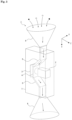
- Fig. 1 is a diagram for explaining a usage example of the measurement device 1.
- the measurement device 1 is used for various purposes such as marine organism investigations, measurement of water quality in aquaculture, selection and investigation of fishing grounds, measurement of microplastics, marine development impact investigations, vessel ballast water investigations, marine resources exploration, measurement of blue carbon, global warming investigations, and carbon content estimation investigations, and examples of the measurement device 1 include measurement devices 1a to 1f shown in Fig. 1 .
- the target objects include microorganisms, marine snow, seabed sands, smoke, and air bubbles.
- Runnability refers to innate behaviors of an organism towards light (external stimuli). Therefore, when a microorganism having runnability is irradiated with light of a specific wavelength, the microorganism moves according to the runnability.
- Fig. 3 is a diagram for explaining a configuration of the measurement device 1 according to the first embodiment.
- Fig. 4 is a diagram in which a part of the measurement device 1 is extracted.
- the main body 2 includes an imaging unit 14 to be described later, the imaging unit 14 being disposed so as to face an illumination surface of the illumination unit 3 via the cell 4.
- the cell 4 has the upper opening 4a and the lower opening 4b connected to the conduction unit 5.
- the conduction unit 5 has openings at the top and bottom and is shaped into a cylinder so as to form therein a flow path stretching from the top to the bottom.
- the flow path of the cell 4 and the flow path of the conduction unit 5 are communicated with each other.
- the conduction unit 5 has one end side connected to have a predetermined angle with respect to the cell 4, and has the other end side extending along a direction in which the cell 4 extends.
- the measurement device 100 can measure the target objects without being affected by water currents.
- the light-shielding unit 7 is provided with a space therein and blocks light from entering inside from the outside.
- the light-shielding unit 7 houses all of the main body 2, the illumination unit 3, and the cell 4, and houses the one end side of the conduction unit 5.
- the control unit 10 is configured to include a microcomputer having, for example, a CPU (Central Processing Unit), a ROM (Read Only Memory), and a RAM (Random Access Memory), and controls the entire measurement device 1.
- the control unit 10 functions as an imaging control unit 21, a class identification unit 22, and a distance/speed measurement unit 23.
- the imaging control unit 21, the class identification unit 22, and the distance/speed measurement unit 23 will be described later in detail.
- the control unit 10 also executes processing of reading data stored in the memory 11, processing of causing the memory 11 to store data, and transmission/reception of various types of data to/from external equipment via the communication unit 12.
- the memory 11 is configured by a nonvolatile memory.
- the communication unit 12 performs wire or wireless data communication with the external equipment.
- the gravity sensor 13 detects a gravitational acceleration (direction of gravity) and outputs the detection result to the control unit 10. Note that the measurement device 1 does not have to include the gravity sensor 13.
- the vision sensor 14a acquires pixel data only when an address event occurs, even when the light emitted from the illumination unit 3 is emitted directly onto a photoelectric conversion element, the vision sensor 14a cannot acquire pixel data, unless the amount of light changes. Therefore, unless the amount or wavelength of light emitted from the illumination unit 3 changes, the illumination unit 3 does not appear on an image captured by the vision sensor 14a.
- the vision sensor 14a and the imaging sensor 14b are arranged so as to capture an image of substantially the same imaging range through the lens 15.
- a half mirror may be arranged between the vision sensor 14a and imaging sensor 14b and the lens 15, so that one of the light beams dispersed by the half mirror is made incident on the vision sensor 14a and the other is made incident on the imaging sensor 14b.
- Target objects are known to reflect or emit light of different wavelengths or intensities with respect to each wavelength of light emitted.
- a target object is irradiated with light of different wavelengths, and an image obtained with the reflected light (or excitation light) is captured, thereby measuring information related to the target object such as the type and size of the target object, the distance of the imaging direction, and the speed of the target object.
- a condition for starting the measurement is designated as the measurement start condition, and, for example, receiving the time to start the measurement or a measurement start command that is input through the communication unit 12 is designated.
- step S1 the control unit 10 reads external environmental information to be described later. Then, in step S2, the control unit 10 determines whether the measurement start condition designated in the measurement settings has been established or not. The control unit 10 repeats step S1 and step S2 until the measurement start condition is established.
- step S4 the imaging control unit 21 creates one image (frame data) on the basis of pixel data input during a predetermined period, detects, as one particle, a pixel group within a predetermined range of the image where a movement is detected, and adds up the detected particles, thereby calculating the number of detected particles.
- the imaging control unit 21 inhibits all of the light-emitting elements 31 of the illumination unit 3 from emitting light (radiating light), as shown in Fig. 8 .
- the imaging control unit 21 also stops driving the imaging unit 14 for the remaining time (e.g., 50 seconds), and shifts the processing to step S9.
- the definition information is provided for each target object and stored in the memory 11.
- the definition information includes the type, movement information, and image information of the target object.
- the movement information is information detected on the basis of an image captured mainly by the vision sensor 14a, and information based on the fact that the target object shown in the lower part of Fig. 2 has moved.
- the movement information is information such as, when the target object is a microorganism, the direction of movement of the microorganism (positive or negative) with respect to the light source and the trajectory of the microorganism.
- the movement information is information such as, when the target object is particulates, the direction of movement and the trajectory of the particulates.
- the image information is information detected on the basis of an image captured mainly by the imaging sensor 14b, and external information of the target object. Note that the image information may be information detected on the basis of an image captured by the vision sensor 14a.
- the definition information may also include the direction of gravity detected by the gravity sensor 13 and external environmental information acquired through the communication unit 12. Depth, position coordinates (latitude, longitude, and plane rectangular coordinates of the measurement spot), electric conductivity, temperatures, ph, concentrations of gases (e.g., methane, hydrogen, helium), concentrations of metals (e.g., manganese, iron), and the like can be considered as the external environmental information.
- gases e.g., methane, hydrogen, helium
- concentrations of metals e.g., manganese, iron
- step S9 the control unit 10 determines whether the measurement end condition is established or not.
- the control unit 10 then repeats steps S3 to S9 until the measurement end condition is established, and when the end condition is established (Yes in step S9), ends the determination processing.
- the measurement device 100 according to the second embodiment performs measurement processing similarly to the measurement device 1 according to the first embodiment.
- the partial light emission operation of step S3 is different from that of the measurement device 1 according to the first embodiment.
- the partial light emission operation of step S3 is now described.
- Fig. 14 and Fig. 15 are diagrams for explaining a light emission operation.
- the imaging control unit 21 performs the partial light emission operation where the light-emitting elements 31 arranged on the outer rim in the illumination unit 3 are caused to emit light but the other light-emitting elements 31 are not caused to emit light.
- the measurement device 200 is different from the measurement device 1 of the first embodiment in being provided with a movement mechanism 201 for moving the cell 4.
- Fig. 17 is a flowchart showing a procedure of cell movement processing.
- the control unit 10 executes the cell movement processing for moving the cell 4.
- the cell 4 is assumed to have moved to the no-cell imaging position.
- the measurement devices 1, 100, 200 measure the number, types, densities, speeds, directions of movement, shape variations and the like of target objects as information on the target objects.
- examples of the information on the target objects may include the sizes and carbon contents of the target objects.
- a measurement device 400 may not include the conduction unit 5, the collection unit 6, and the light-shielding unit 7. That is, the measurement device 400 may include the main body 2, the illumination unit 3, and the cell 4, and the opening 4a and the opening 4b of the cell 4 may be opened.
- FIG. 23 is a diagram for explaining a modification of the measurement device according to the second embodiment.
- a measurement device 600 according to the second embodiment may have the main body 2 housed in a pressure-resistant container 601 for protecting the main body 2 from high water pressure in deep sea.
- the pressure-resistant container 601 may be in any shape.
- Fig. 24 is a diagram for explaining calibration processing according to modification 1.
- Fig. 25 is a flowchart showing a procedure of the calibration processing.
- a measurement device according to modification 1 may have the configuration of any of the measurement devices 1, 100, 200, 300, 400, 500, and 600 according to the first embodiment to the third embodiment and other configuration examples described above, but the measurement device 1 according to the first embodiment will now be described as an example.
- step S22 the imaging control unit 21 causes the illumination unit 3 to emit light having the wavelength set in step S21, and causes the vision sensor 14a to capture an image.
- step S26 the imaging control unit 21 determines a wavelength at which the number of target objects TO counted in step S24 is the highest, as a wavelength to be used in the measurement processing.
- Fig. 26 is a diagram for explaining a configuration of a measurement device 700 according to modification 2.
- modification 1 the color of the background is changed by changing the wavelength of the light emitted from the illumination unit 3, but in modification 2, the color of the background is changed by switching background plates of different colors.
- the measurement device 700 includes a background device 701 in place of the illumination unit 3, and a movement mechanism 702. Note that the illumination unit for emitting light in the imaging range of the imaging unit 14 may be provided separately.
- the background device 701 has a plurality of background plates 710 of different colors connected to each other into a polygon, and a space is formed therein.
- the main body 2, the cell 4 and the like are provided inside of the background device 701.
- the background device 701 is arranged in such a manner that one of the background plate 710 appears as the background of the imaging range of the imaging unit 14.
- control unit 10 drives and controls the movement mechanism 702 in such a manner that the background plates 710 of different colors appear as the background of the imaging range of the imaging unit 14.
- the measurement device 700 can image and measure the target objects TO efficiently as with modification 1 in which the illumination unit 3 emits light of different wavelengths.
- electronic ink may be used as a method for changing the background color.
- the measurement device 1 can also achieve a reduction in overexposure, high-speed imaging, a reduction in power consumption, and low computational cost.
- the illumination unit 3 includes the plurality of light-emitting elements 31, and the imaging control unit 21 is considered to cause some of the light-emitting elements 31 of the illumination unit 3 to emit light.
- the image (pixel data) can be acquired by driving the vision sensor 14a in conjunction with the illumination unit 3, further reducing the power consumption.
- the measurement device 1 can perform an efficient measurement.
- the imaging control unit 21 is considered to drive all of the photoelectric conversion elements of the vision sensor 14a when all of the light-emitting elements 31 of the illumination unit 3 emit light.
- the image (pixel data) can be acquired by driving the vision sensor 14a in conjunction with the illumination unit 3, allowing for an efficient measurement.
- the cell 4 having the openings 4a, 4b through which particles flow in and out is considered to be provided between the illumination unit 3 and the vision sensor 14a, and the imaging control unit 21 is considered to emit light from some of the light-emitting elements 31 corresponding to the openings 4a, 4b of the cell 4.
- the particles flowing in and out of the cell 4 can be measured, and whether to continue the measurement or not can be determined.
- the measurement device 1 can perform an efficient measurement.
- the imaging control unit 21 is considered to emit light of a predetermined wavelength from some of the light-emitting elements 31 of the illumination unit 3, and emit light of a different wavelength from the other light-emitting elements 31.
- microorganisms having runnability can be measured efficiently.
- the cell having the openings 4a, 4b through which particles flow in and out, and the movement mechanism 201 for moving the cell 4 to the first position (cell-present position) between the illumination unit 3 and the vision sensor 14a and the second position (no-cell position) which is away from between the illumination unit 3 and the vision sensor 14a, and the imaging control unit 21 is considered to move the cell 4 to the first position or the second position by driving the movement mechanism 201.
- the measurement device 1 is considered to include the light-shielding unit 7 that houses the illumination unit 3, the vision sensor 14a, and the cell 4 and blocks light from coming in from the outside. Therefore, the impact of the light coming from the outside can be reduced, allowing for a precise measurement.
- the measurement device 1 is considered to include the conduction unit 5 having one end side connected to the openings 4a, 4b of the cell 4 so as to have a predetermined angle, and the light-shielding unit 7 is considered to house one end side of the conduction unit 5.
- one end side of the conduction unit 5 is connected so as to have a predetermined angle with respect to the cell 4, the entry of external light into the cell 4 through the conduction unit 5 can be reduced, allowing for a precise measurement.
- the imaging control unit 21 is considered to calculate the number of target objects at each of a plurality of different wavelengths on the basis of each of the images captured by the vision sensor 14a when light of the plurality of different wavelengths is emitted from the illumination unit 3, and determine a wavelength at which the most target objects are detected, as the wavelength of the light that is emitted from the illumination unit 3 in the measurement by the measurement unit (measurement processing).
- the colors of the target objects and the background color are no longer similar to each other, so the target objects can be measured efficiently.
- the imaging control unit 21 is considered to calculate the number of target objects at each of a plurality of different wavelengths on the basis of each of the images captured by the vision sensor 14a when light of the plurality of different wavelengths is emitted from the illumination unit 3, and determine a wavelength at which a specific number or more of target objects is detected, which is a wavelength with the least amount of power consumption, as the wavelength of the light that is emitted from the illumination unit 3 in the measurement by the measurement unit.
- the target objects can be measured efficiently while reducing power consumption.
- the imaging control unit 21 is considered to calculate the number of target objects at each of a plurality of different wavelengths on the basis of each of the images captured by the vision sensor 14a when light of the plurality of different wavelengths is emitted from the illumination unit 3, and determine a wavelength at which a specific number or more of target objects is detected, which is a wavelength with the least amount of noise, as the wavelength of the light that is emitted from the illumination unit in the measurement by the measurement unit.
- the target objects can be measured efficiently while reducing noise.
- the measurement method causes the vision sensor to acquire pixel data asynchronously in accordance with the amount of light incident on each of a plurality of pixels arranged two-dimensionally, the vision sensor being arranged facing an illumination surface of the illumination unit emitting light, and measures information related to a target object on the basis of the image captured by the vision sensor.
- the program according to the present technology described above causes the vision sensor to acquire pixel data asynchronously in accordance with the amount of light incident on each of a plurality of pixels arranged two-dimensionally, the vision sensor being arranged facing an illumination surface of the illumination unit emitting light, and causes the measurement device to perform the processing of measuring information related to a target object on the basis of the image captured by the vision sensor.
- the program can be recorded in advance in an HDD serving as a recording medium embedded in a device such as a computer device or a ROM or the like in a microcomputer that includes a CPU.
- the program can be installed from the removable recording medium to a personal computer or the like and can also be downloaded from a download site via a network such as a LAN (Local Area Network) or the Internet.
- a network such as a LAN (Local Area Network) or the Internet.
- the present technology can also adopt the following configurations.
Landscapes
- Chemical & Material Sciences (AREA)
- Physics & Mathematics (AREA)
- Life Sciences & Earth Sciences (AREA)
- Health & Medical Sciences (AREA)
- Pathology (AREA)
- Immunology (AREA)
- General Physics & Mathematics (AREA)
- Analytical Chemistry (AREA)
- Biochemistry (AREA)
- General Health & Medical Sciences (AREA)
- Dispersion Chemistry (AREA)
- Engineering & Computer Science (AREA)
- Food Science & Technology (AREA)
- Medicinal Chemistry (AREA)
- Mathematical Physics (AREA)
- Theoretical Computer Science (AREA)
- Spectroscopy & Molecular Physics (AREA)
- Length Measuring Devices By Optical Means (AREA)
Applications Claiming Priority (2)
| Application Number | Priority Date | Filing Date | Title |
|---|---|---|---|
| JP2021138154 | 2021-08-26 | ||
| PCT/JP2022/030816 WO2023026880A1 (fr) | 2021-08-26 | 2022-08-12 | Dispositif de mesure, procédé de mesure et programme |
Publications (1)
| Publication Number | Publication Date |
|---|---|
| EP4394355A1 true EP4394355A1 (fr) | 2024-07-03 |
Family
ID=85322762
Family Applications (1)
| Application Number | Title | Priority Date | Filing Date |
|---|---|---|---|
| EP22861169.5A Pending EP4394355A1 (fr) | 2021-08-26 | 2022-08-12 | Dispositif de mesure, procédé de mesure et programme |
Country Status (5)
| Country | Link |
|---|---|
| EP (1) | EP4394355A1 (fr) |
| JP (1) | JPWO2023026880A1 (fr) |
| KR (1) | KR20240047373A (fr) |
| CN (1) | CN117836608A (fr) |
| WO (1) | WO2023026880A1 (fr) |
Family Cites Families (6)
| Publication number | Priority date | Publication date | Assignee | Title |
|---|---|---|---|---|
| JPWO2012173130A1 (ja) * | 2011-06-17 | 2015-02-23 | 株式会社日立製作所 | 液体分析装置 |
| WO2017145816A1 (fr) * | 2016-02-24 | 2017-08-31 | ソニー株式会社 | Instrument de mesure optique, cytomètre en flux et compteur de rayonnement |
| JP2021044599A (ja) * | 2018-01-05 | 2021-03-18 | 株式会社ニコン | 検出装置およびセンサ |
| JP7007225B2 (ja) | 2018-03-23 | 2022-01-24 | Jfeアドバンテック株式会社 | 特定種の植物プランクトンの存在量の算出方法及び算出装置、及び特定種の植物プランクトンによる赤潮発生の予兆検知方法及び予兆検知装置 |
| JP2021021568A (ja) * | 2019-07-24 | 2021-02-18 | Optech Innovation合同会社 | 光吸収量差分計測装置及び光吸収量差分計測方法、並びに光吸収量差分画像の撮影装置及び光吸収量差分画像の撮影方法 |
| CN114600116A (zh) * | 2019-10-30 | 2022-06-07 | 索尼集团公司 | 对象识别系统、对象识别系统的信号处理方法、以及电子装置 |
-
2022
- 2022-08-12 JP JP2023543812A patent/JPWO2023026880A1/ja active Pending
- 2022-08-12 WO PCT/JP2022/030816 patent/WO2023026880A1/fr active Application Filing
- 2022-08-12 CN CN202280056742.9A patent/CN117836608A/zh active Pending
- 2022-08-12 EP EP22861169.5A patent/EP4394355A1/fr active Pending
- 2022-08-12 KR KR1020247004542A patent/KR20240047373A/ko unknown
Also Published As
| Publication number | Publication date |
|---|---|
| WO2023026880A1 (fr) | 2023-03-02 |
| JPWO2023026880A1 (fr) | 2023-03-02 |
| KR20240047373A (ko) | 2024-04-12 |
| CN117836608A (zh) | 2024-04-05 |
Similar Documents
| Publication | Publication Date | Title |
|---|---|---|
| JP6959614B2 (ja) | 分析装置,及びフローサイトメータ | |
| US10222688B2 (en) | Continuous particle imaging and classification system | |
| Samson et al. | A system for high-resolution zooplankton imaging | |
| EP3611462B1 (fr) | Appareil, système et procédé pour augmenter la précision de mesure dans un dispositif d'imagerie à particules | |
| CN103003683B (zh) | 用于通过使用光分布来提高粒子成像设备中的测量精确度的装置、系统和方法 | |
| CN108520511A (zh) | 一种基于鱼探仪的水下鱼类目标探测与识别方法 | |
| WO2021215173A1 (fr) | Dispositif de mesure et procédé de commande d'imagerie | |
| WO2022137243A1 (fr) | Technique optique pour l'analyse d'insectes, de crevettes et de poissons | |
| Wang et al. | Vision-based in situ monitoring of plankton size spectra via a convolutional neural network | |
| EP4394355A1 (fr) | Dispositif de mesure, procédé de mesure et programme | |
| EP4350284A1 (fr) | Dispositif de mesure, procédé de mesure et programme | |
| KR101631260B1 (ko) | 어장관리 시스템 | |
| KR101268596B1 (ko) | 정사각 코드북과 다중 경계 값이 적용된 텍스쳐 특징을 이용한 전경 검출 장치 및 방법 | |
| Cao et al. | Marine animal classification using UMSLI in HBOI optical test facility | |
| CN110738698A (zh) | 浮水式海底数据测量方法、装置和电子设备 | |
| Marini et al. | GUARD1: An autonomous system for gelatinous zooplankton image-based recognition | |
| KR102141531B1 (ko) | 적조 탐지장치 및 탐지방법 | |
| WO2023026551A1 (fr) | Dispositif de mesure, procédé de mesure et programme | |
| EP4350307A1 (fr) | Dispositif de mesure, procédé de mesure et programme | |
| Kuanysheva et al. | Identification of Bioluminescent Deep Ocean Macro Organisms Using Computer Vision | |
| Monari et al. | UDEEP: Edge-based Computer Vision for In-Situ Underwater Crayfish and Plastic Detection | |
| CN116940948A (zh) | 服务器装置、生成方法、电子装置生成方法、数据库生成方法和电子装置 | |
| WO2023112532A1 (fr) | Dispositif de mesure, procédé de mesure et programme | |
| KR20240076336A (ko) | 수조 내의 특정 개체를 분리하기 위한 시스템, 방법 및 컴퓨터 프로그램 | |
| CN116529388A (zh) | 测量装置、测量方法和测量系统 |
Legal Events
| Date | Code | Title | Description |
|---|---|---|---|
| STAA | Information on the status of an ep patent application or granted ep patent |
Free format text: STATUS: THE INTERNATIONAL PUBLICATION HAS BEEN MADE |
|
| PUAI | Public reference made under article 153(3) epc to a published international application that has entered the european phase |
Free format text: ORIGINAL CODE: 0009012 |
|
| STAA | Information on the status of an ep patent application or granted ep patent |
Free format text: STATUS: REQUEST FOR EXAMINATION WAS MADE |
|
| 17P | Request for examination filed |
Effective date: 20240317 |
|
| AK | Designated contracting states |
Kind code of ref document: A1 Designated state(s): AL AT BE BG CH CY CZ DE DK EE ES FI FR GB GR HR HU IE IS IT LI LT LU LV MC MK MT NL NO PL PT RO RS SE SI SK SM TR |