EP4394353A1 - Coal analyzer, coal analysis method, mixed coal preparation method, and coke production method - Google Patents
Coal analyzer, coal analysis method, mixed coal preparation method, and coke production method Download PDFInfo
- Publication number
- EP4394353A1 EP4394353A1 EP22875935.3A EP22875935A EP4394353A1 EP 4394353 A1 EP4394353 A1 EP 4394353A1 EP 22875935 A EP22875935 A EP 22875935A EP 4394353 A1 EP4394353 A1 EP 4394353A1
- Authority
- EP
- European Patent Office
- Prior art keywords
- coal
- vitrinite
- total inert
- inert amount
- reflectance
- Prior art date
- Legal status (The legal status is an assumption and is not a legal conclusion. Google has not performed a legal analysis and makes no representation as to the accuracy of the status listed.)
- Pending
Links
Images



Classifications
-
- G—PHYSICS
- G01—MEASURING; TESTING
- G01N—INVESTIGATING OR ANALYSING MATERIALS BY DETERMINING THEIR CHEMICAL OR PHYSICAL PROPERTIES
- G01N21/00—Investigating or analysing materials by the use of optical means, i.e. using sub-millimetre waves, infrared, visible or ultraviolet light
- G01N21/17—Systems in which incident light is modified in accordance with the properties of the material investigated
- G01N21/55—Specular reflectivity
-
- C—CHEMISTRY; METALLURGY
- C10—PETROLEUM, GAS OR COKE INDUSTRIES; TECHNICAL GASES CONTAINING CARBON MONOXIDE; FUELS; LUBRICANTS; PEAT
- C10B—DESTRUCTIVE DISTILLATION OF CARBONACEOUS MATERIALS FOR PRODUCTION OF GAS, COKE, TAR, OR SIMILAR MATERIALS
- C10B45/00—Other details
-
- C—CHEMISTRY; METALLURGY
- C10—PETROLEUM, GAS OR COKE INDUSTRIES; TECHNICAL GASES CONTAINING CARBON MONOXIDE; FUELS; LUBRICANTS; PEAT
- C10B—DESTRUCTIVE DISTILLATION OF CARBONACEOUS MATERIALS FOR PRODUCTION OF GAS, COKE, TAR, OR SIMILAR MATERIALS
- C10B57/00—Other carbonising or coking processes; Features of destructive distillation processes in general
- C10B57/04—Other carbonising or coking processes; Features of destructive distillation processes in general using charges of special composition
-
- C—CHEMISTRY; METALLURGY
- C10—PETROLEUM, GAS OR COKE INDUSTRIES; TECHNICAL GASES CONTAINING CARBON MONOXIDE; FUELS; LUBRICANTS; PEAT
- C10L—FUELS NOT OTHERWISE PROVIDED FOR; NATURAL GAS; SYNTHETIC NATURAL GAS OBTAINED BY PROCESSES NOT COVERED BY SUBCLASSES C10G OR C10K; LIQUIFIED PETROLEUM GAS; USE OF ADDITIVES TO FUELS OR FIRES; FIRE-LIGHTERS
- C10L5/00—Solid fuels
- C10L5/02—Solid fuels such as briquettes consisting mainly of carbonaceous materials of mineral or non-mineral origin
- C10L5/04—Raw material of mineral origin to be used; Pretreatment thereof
-
- G—PHYSICS
- G01—MEASURING; TESTING
- G01N—INVESTIGATING OR ANALYSING MATERIALS BY DETERMINING THEIR CHEMICAL OR PHYSICAL PROPERTIES
- G01N21/00—Investigating or analysing materials by the use of optical means, i.e. using sub-millimetre waves, infrared, visible or ultraviolet light
- G01N21/17—Systems in which incident light is modified in accordance with the properties of the material investigated
- G01N21/25—Colour; Spectral properties, i.e. comparison of effect of material on the light at two or more different wavelengths or wavelength bands
- G01N21/27—Colour; Spectral properties, i.e. comparison of effect of material on the light at two or more different wavelengths or wavelength bands using photo-electric detection ; circuits for computing concentration
- G01N21/274—Calibration, base line adjustment, drift correction
-
- G—PHYSICS
- G01—MEASURING; TESTING
- G01N—INVESTIGATING OR ANALYSING MATERIALS BY DETERMINING THEIR CHEMICAL OR PHYSICAL PROPERTIES
- G01N21/00—Investigating or analysing materials by the use of optical means, i.e. using sub-millimetre waves, infrared, visible or ultraviolet light
- G01N21/84—Systems specially adapted for particular applications
-
- G—PHYSICS
- G01—MEASURING; TESTING
- G01N—INVESTIGATING OR ANALYSING MATERIALS BY DETERMINING THEIR CHEMICAL OR PHYSICAL PROPERTIES
- G01N33/00—Investigating or analysing materials by specific methods not covered by groups G01N1/00 - G01N31/00
- G01N33/22—Fuels; Explosives
- G01N33/222—Solid fuels, e.g. coal
-
- C—CHEMISTRY; METALLURGY
- C10—PETROLEUM, GAS OR COKE INDUSTRIES; TECHNICAL GASES CONTAINING CARBON MONOXIDE; FUELS; LUBRICANTS; PEAT
- C10L—FUELS NOT OTHERWISE PROVIDED FOR; NATURAL GAS; SYNTHETIC NATURAL GAS OBTAINED BY PROCESSES NOT COVERED BY SUBCLASSES C10G OR C10K; LIQUIFIED PETROLEUM GAS; USE OF ADDITIVES TO FUELS OR FIRES; FIRE-LIGHTERS
- C10L2290/00—Fuel preparation or upgrading, processes or apparatus therefore, comprising specific process steps or apparatus units
- C10L2290/24—Mixing, stirring of fuel components
-
- C—CHEMISTRY; METALLURGY
- C10—PETROLEUM, GAS OR COKE INDUSTRIES; TECHNICAL GASES CONTAINING CARBON MONOXIDE; FUELS; LUBRICANTS; PEAT
- C10L—FUELS NOT OTHERWISE PROVIDED FOR; NATURAL GAS; SYNTHETIC NATURAL GAS OBTAINED BY PROCESSES NOT COVERED BY SUBCLASSES C10G OR C10K; LIQUIFIED PETROLEUM GAS; USE OF ADDITIVES TO FUELS OR FIRES; FIRE-LIGHTERS
- C10L2290/00—Fuel preparation or upgrading, processes or apparatus therefore, comprising specific process steps or apparatus units
- C10L2290/60—Measuring or analysing fractions, components or impurities or process conditions during preparation or upgrading of a fuel
-
- G—PHYSICS
- G01—MEASURING; TESTING
- G01N—INVESTIGATING OR ANALYSING MATERIALS BY DETERMINING THEIR CHEMICAL OR PHYSICAL PROPERTIES
- G01N1/00—Sampling; Preparing specimens for investigation
- G01N1/28—Preparing specimens for investigation including physical details of (bio-)chemical methods covered elsewhere, e.g. G01N33/50, C12Q
- G01N1/286—Preparing specimens for investigation including physical details of (bio-)chemical methods covered elsewhere, e.g. G01N33/50, C12Q involving mechanical work, e.g. chopping, disintegrating, compacting, homogenising
-
- G—PHYSICS
- G01—MEASURING; TESTING
- G01N—INVESTIGATING OR ANALYSING MATERIALS BY DETERMINING THEIR CHEMICAL OR PHYSICAL PROPERTIES
- G01N1/00—Sampling; Preparing specimens for investigation
- G01N1/28—Preparing specimens for investigation including physical details of (bio-)chemical methods covered elsewhere, e.g. G01N33/50, C12Q
- G01N1/32—Polishing; Etching
-
- G—PHYSICS
- G01—MEASURING; TESTING
- G01N—INVESTIGATING OR ANALYSING MATERIALS BY DETERMINING THEIR CHEMICAL OR PHYSICAL PROPERTIES
- G01N1/00—Sampling; Preparing specimens for investigation
- G01N1/28—Preparing specimens for investigation including physical details of (bio-)chemical methods covered elsewhere, e.g. G01N33/50, C12Q
- G01N1/36—Embedding or analogous mounting of samples
- G01N2001/364—Embedding or analogous mounting of samples using resins, epoxy
-
- G—PHYSICS
- G01—MEASURING; TESTING
- G01N—INVESTIGATING OR ANALYSING MATERIALS BY DETERMINING THEIR CHEMICAL OR PHYSICAL PROPERTIES
- G01N21/00—Investigating or analysing materials by the use of optical means, i.e. using sub-millimetre waves, infrared, visible or ultraviolet light
- G01N21/17—Systems in which incident light is modified in accordance with the properties of the material investigated
- G01N21/55—Specular reflectivity
- G01N2021/559—Determining variation of specular reflection within diffusively reflecting sample
Definitions
- the total inert amount of coal is measured using a microscope in accordance with JIS M 8816-1992 (Solid mineral fuels-Methods of microscopical measurement for the macerals and reflectance).
- the present invention has been made in view of the above points, and an object thereof is to easily obtain a ratio of at least one of the microstructural component groups of coal.
- the present invention provides the following [1] to [16].
- the 12 types of microstructural components are telinite, collinite, degradinite, sporinite, cutinite, alginite, resinite, semi-fusinite, fusinite, micrinite, sclerotinite, and macrinite.
- Microstructural components belonging to exinite are four types: sporinite, cutinite, alginite, and resinite.
- FIG. 1 is a block diagram illustrating a configuration of a coal analyzer 1.
- the coal analyzer 1 includes an image acquisition unit 2, an identification unit 3, a calculation unit 4, and a correction unit 5.
- the microscope 6 captures a surface image of the coal sample 7.
- FIG. 2 is a flowchart illustrating a flow of processing executed by respective units included in the coal analyzer 1.
- the entire surface of the coal sample 7 is imaged to obtain about 2000 individual images, and the obtained individual images are combined to obtain one huge surface image.
- coal particles 9 (coal particle 9a, coal particle 9b, and coal particle 9c) embedded in the resin 10 are partly exposed.
- vitrinite 11 is indicated by a vertical broken line
- inert 12 is indicated by a horizontal broken line.
- the coal particle 9a in the upper part of the surface image 8 is formed of the vitrinite 11.
- the identification unit 3 of the coal analyzer 1 extracts only pixels corresponding to the coal particles 9 from the surface image 8 (step S102).
- the resin 10 takes on a blackish color.
- the surface image 8 is subjected to differential processing, a boundary between the coal particle 9 and the resin 10, which has a large differential value, is detected, and only each pixel inside the boundary (that is, the coal particle 9) is acquired.
- Each pixel constituting the surface image 8 includes luminance information.
- a calibration curve between luminance and reflectance is created in advance using a standard test piece with known reflectance.
- the identification unit 3 of the coal analyzer 1 converts the luminance of each pixel into reflectance based on the created calibration curve. In this manner, the reflectance of each pixel of the coal particle 9 is obtained.
- the identification unit 3 of the coal analyzer 1 collects and aggregates the reflectances of the respective pixels to create an aggregate reflectance histogram of all the coal particles (step S103).
- FIG. 4 is an aggregate reflectance histogram of all the coal particles.
- the horizontal axis represents reflectance (unit: %), and the vertical axis represents frequency (number of cases) (the same applies hereinafter).
- the reflectance distribution of vitrinite is a normal distribution.
- the identification unit 3 of the coal analyzer 1 roughly determines the threshold of a vitrinite reflectance range in the aggregate reflectance histogram of all the coal particles. Specifically, as illustrated in FIG. 4 , a minimum threshold 13 and a maximum threshold 14 of the vitrinite reflectance range are determined (step S104).
- the thresholds it is preferable to determine portions where the reflectance histogram changes rapidly as the thresholds.
- the thresholds can be determined based on the differential value or the curvature of the reflectance histogram.
- the identification unit 3 of the coal analyzer 1 fits a normal distribution to the reflectance histogram of an individual coal particle (refer to FIG. 5 to be described later) on the assumption that the reflectance distribution of vitrinite is a normal distribution (step S105).
- the vitrinite reflectance range of the individual coal particle is thus determined.
- the aggregate reflectance histogram of all the coal particles may be used to determine the vitrinite reflectance range
- the vitrinite reflectance range varies for each individual coal particle in reality. For this reason, determining the vitrinite reflectance range for each individual coal particle can make the finally obtained total inert amount more accurate.
- FIG. 5 illustrates a minimum value 17 and a maximum value 18 of the vitrinite reflectance.
- the minimum value 17 of the vitrinite reflectance is obtained from the formula "u - 3 ⁇ ".
- the maximum value 18 of the vitrinite reflectance is obtained from the formula "u + 3 ⁇ ”.
- FIG. 5 also illustrates the thresholds (minimum threshold 13 and maximum threshold 14) of the previously determined vitrinite reflectance range.
- the identification unit 3 of the coal analyzer 1 determines the vitrinite reflectance and the inert reflectance of the coal particle based on the following formulae (step S109).
- the calculation unit 4 of the coal analyzer 1 calculates the average reflectance Ro (unit:%) of vitrinite based on the following formula (step 5111).
- the "average reflectance Ro of vitrinite” is also simply referred to as "Ro”.
- Ro represents the degree of maturation of coal.
- Ro ⁇ (reflectance of vitrinite pixel) / number of vitrinite pixels
- the "vitrinite pixel” means a pixel identified as vitrinite.
- an “inert pixel” means a pixel identified as inert.
- the microstructural components of coal in the field of view are identified and counted based on a criterion such as a pattern while the stage of a microscope on which the coal sample is placed is manually moved at regular intervals.
- the coefficient a is 1 or 2/3 in consideration of the active component of semi-fusinite.
- the calculation herein uses 1 as the coefficient a, but the present invention is not limited thereto.
- the correction unit 5 of the coal analyzer 1 corrects the total inert amount calculated by the calculation unit 4 (step S113).
- Ro and the total inert amount obtained using the coal analyzer 1 (coal analysis method) of the present embodiment may be referred to as “Ro (automatic)” and the “total inert amount (automatic)", respectively.
- Ro and the total inert amount obtained by the conventional method may be referred to as “Ro (manual)” and the “total inert amount (manual)", respectively.
- FIG. 6 is a relationship diagram between Ro (manual) and Ro (automatic).
- FIG. 8 illustrates a semi-fusinite reflectance 19 (a histogram of the semi-fusinite reflectance).
- the present inventors obtained the ratio (unit:%) of semi-fusinite by the conventional method as in the case of the total inert amount.
- this may be referred to as a "semi-fusinite ratio (manual)".
- FIG. 9 is a relationship diagram between Ro (automatic) and the semi-fusinite ratio (manual).
- FIG. 10 is a relationship diagram between the total inert volume (manual) and the corrected total inert amount (automatic).
- the corrected total inert amount (automatic) obtained by the correction using the multiple regression coefficient is also accurate.
Landscapes
- Chemical & Material Sciences (AREA)
- Life Sciences & Earth Sciences (AREA)
- Physics & Mathematics (AREA)
- Health & Medical Sciences (AREA)
- Pathology (AREA)
- Immunology (AREA)
- Analytical Chemistry (AREA)
- Biochemistry (AREA)
- General Health & Medical Sciences (AREA)
- General Physics & Mathematics (AREA)
- Engineering & Computer Science (AREA)
- Oil, Petroleum & Natural Gas (AREA)
- Organic Chemistry (AREA)
- Materials Engineering (AREA)
- Geochemistry & Mineralogy (AREA)
- Environmental & Geological Engineering (AREA)
- General Life Sciences & Earth Sciences (AREA)
- Geology (AREA)
- Spectroscopy & Molecular Physics (AREA)
- Food Science & Technology (AREA)
- Medicinal Chemistry (AREA)
- Theoretical Computer Science (AREA)
- Mathematical Physics (AREA)
- Investigating Or Analysing Materials By Optical Means (AREA)
- Coke Industry (AREA)
- Analysing Materials By The Use Of Radiation (AREA)
Abstract
Description
- The present invention relates to a coal analyzer, a coal analysis method, a mixed coal preparation method, and a coke production method.
- Coke is produced from coal with various brands blended according to its product indexes.
- Coal used for coke production is analyzed in advance for the structural components (Patent Literature 1).
- Patent Literature 1:
JP S58-35442 A - One of important product indexes of coke is cold coke strength.
- There are three types of microstructural component groups (maceral groups) of coal: vitrinite, exinite, and inertinite. Among them, for example, inertinite is chemically inert and affects the cold coke strength.
- For this reason, the ratio of inertinite (total inert amount) in coal used for coke production is measured.
- Conventionally, the total inert amount of coal is measured using a microscope in accordance with JIS M 8816-1992 (Solid mineral fuels-Methods of microscopical measurement for the macerals and reflectance).
- In this case, it is necessary to individually identify a microstructural component (maceral) belonging to inertinite such as semi-fusinite, thereby making the measurement very complicated. In addition, since the identification is performed based on a criterion such as a pattern, the identification result is largely dependent on a person, and such identification is also time-consuming.
- The same applies to the measurement of the ratios of vitrinite and exinite, which are the other microstructural component groups.
- The present invention has been made in view of the above points, and an object thereof is to easily obtain a ratio of at least one of the microstructural component groups of coal.
- As a result of intensive studies, the present inventors have found that the above object is achieved by adopting the following constitution, and have completed the present invention.
- That is, the present invention provides the following [1] to [16].
- [1] A coal analyzer comprising: an image acquisition unit that acquires a surface image of a coal sample; an identification unit that identifies a microstructural component group included in the surface image; and a calculation unit that calculates a ratio of at least one of the microstructural component groups.
- [2] The coal analyzer according to [1], wherein the identification unit identifies the microstructural component group based on a reflectance of the microstructural component group.
- [3] The coal analyzer according to [1] or [2], wherein the calculation unit calculates an average reflectance Ro of vitrinite, which is one of the microstructural component groups.
- [4] The coal analyzer according to any one of [1] to [3], wherein the calculation unit calculates a total inert amount that is a ratio of inertinite among the microstructural component groups.
- [5] The coal analyzer according to [4], further comprising a correction unit that corrects the total inert amount.
- [6] The coal analyzer according to [5], wherein the calculation unit calculates an average reflectance Ro of vitrinite, which is one of the microstructural component groups, and the correction unit corrects the total inert amount using the total inert amount and the average reflectance Ro of vitrinite.
- [7] The coal analyzer according to [6], wherein the correction unit corrects the total inert amount using a multiple regression coefficient that is determined in advance, with the total inert amount and the average reflectance Ro of vitrinite as variables.
- [8] A coal analysis method comprising: acquiring a surface image of a coal sample; identifying a microstructural component group included in the surface image; and calculating a ratio of at least one of the microstructural component groups.
- [9] The coal analysis method according to [8], further comprising identifying the microstructural component group based on a reflectance of the microstructural component group.
- [10] The coal analysis method according to [8] or [9], further comprising calculating an average reflectance Ro of vitrinite, which is one of the microstructural component groups.
- [11] The coal analysis method according to any one of [8] to [10], further comprising calculating a total inert amount that is a ratio of inertinite among the microstructural component groups.
- [12] The coal analysis method according to [11], further comprising correcting the total inert amount.
- [13] The coal analysis method according to [12], further comprising: calculating an average reflectance Ro of vitrinite, which is one of the microstructural component groups; and correcting the total inert amount using the total inert amount and the average reflectance Ro of vitrinite.
- [14] The coal analysis method according to [13], further comprising correcting the total inert amount using a multiple regression coefficient that is determined in advance, with the total inert amount and the average reflectance Ro of vitrinite as variables.
- [15] A mixed coal preparation method comprising: blending multiple types of coals to prepare mixed coal; and identifying a total inert amount of at least part of the coal using the method according to any one of [8] to [14].
- [16] A coke production method comprising using the mixed coal prepared by the method according to [15] to obtain coke.
- According to the present invention, the ratio of at least one of the microstructural component groups of coal can be easily obtained.
-
- [
FIG. 1] FIG. 1 is a block diagram illustrating a configuration of a coal analyzer. - [
FIG. 2] FIG. 2 is a flowchart illustrating a flow of processing executed by respective units included in the coal analyzer. - [
FIG. 3] FIG. 3 is a view illustrating a surface image of a coal sample. - [
FIG. 4] FIG. 4 is an aggregate reflectance histogram of all coal particles. - [
FIG. 5] FIG. 5 is a reflectance histogram of one coal particle. - [
FIG. 6] FIG. 6 is a relationship diagram between Ro (manual) and Ro (automatic). - [
FIG. 7] FIG. 7 is a relationship diagram between a total inert amount (manual) and a total inert amount (automatic). - [
FIG. 8] FIG. 8 is a reflectance histogram of one coal particle, which histogram illustrates a semi-fusinite reflectance. - [
FIG. 9] FIG. 9 is a relationship diagram between Ro (automatic) and a semi-fusinite ratio (manual). - [
FIG. 10] FIG. 10 is a relationship diagram between the total inert amount (manual) and a corrected total inert amount (automatic). - Coal is composed of microstructural components having different gloss and shape under a microscope.
- A microstructural component (maceral) and a microstructural component group (maceral group) of coal will be described.
- The microstructural component (maceral) of coal is a fine organic component of coal that is classified into 12 types with a microscope.
- Specifically, the 12 types of microstructural components are telinite, collinite, degradinite, sporinite, cutinite, alginite, resinite, semi-fusinite, fusinite, micrinite, sclerotinite, and macrinite.
- The microstructural component group (maceral group) of coal is a component group of microstructural components of coal having similar properties under a microscope, and is classified into three types.
- Specifically, the three types of microstructural component groups are vitrinite, exinite, and inertinite (also referred to as "inert").
- Microstructural components belonging to vitrinite are three types: telinite, collinite, and degradinite.
- Microstructural components belonging to exinite are four types: sporinite, cutinite, alginite, and resinite.
- Microstructural components belonging to inertinite are five types: semi-fusinite, fusinite, micrinite, sclerotinite, and macrinite.
- In general, a total inert amount representing the ratio of inertinite among the three types of microstructural components (vitrinite, exinite, and inertinite) is used for the design of cold coke strength.
- For this reason, the total inert amount of coal is obtained in the present embodiment.
- Hereinafter, a coal analyzer of the present embodiment will be described with reference to
FIGS. 1 to 10 . The following description doubles as a description of the coal analysis method of the present embodiment. -
FIG. 1 is a block diagram illustrating a configuration of acoal analyzer 1. - The
coal analyzer 1 includes animage acquisition unit 2, anidentification unit 3, acalculation unit 4, and acorrection unit 5. - The
image acquisition unit 2, theidentification unit 3, thecalculation unit 4, and thecorrection unit 5 are composed of, for example, a central processing unit (CPU), a main storage device such as a dynamic random access memory (DRAM) connected to the CPU, a mass storage device such as a solid state drive (SSD) or a hard disk drive (HDD) connected to the CPU, and a program for operating the CPU. - Processing executed by these units will be described later.
- The
coal analyzer 1 is connected to amicroscope 6. Acoal sample 7 is placed on a stage (not shown) of themicroscope 6. - The
coal sample 7 is prepared in accordance with JIS M 8816-1992. - More specifically, the
coal sample 7 is obtained by pulverizing the collected coal, embedding the obtained coal particles in a resin, curing the resin, and then polishing the surface of the cured object. - The
microscope 6 captures a surface image of thecoal sample 7. - It is preferable that the
microscope 6 has a function of designating a macro imaging range in advance, capturing a plurality of micro images while automatically moving the stage, and finally combining the captured micro images into a macro image. - In the present embodiment, for example, the size of the micro image is about 800 um in length and 530 um in width, and an oil immersion objective lens (magnification: 20 times) is used as the objective lens.
- However, as long as the surface image of the
coal sample 7 can be captured, themicroscope 6 may not have the above function, and another objective lens may be used. -
FIG. 2 is a flowchart illustrating a flow of processing executed by respective units included in thecoal analyzer 1. - First, the
image acquisition unit 2 of thecoal analyzer 1 causes themicroscope 6 to capture a surface image of thecoal sample 7, and acquires the captured surface image (step S101). - Only one surface image of the
coal sample 7 may be captured to calculate the total inert amount, but only one surface image is merely part of the surface of thecoal sample 7, and is thus less representative. To ensure the representativeness, it is preferable to image a plurality of portions of the surface of thecoal sample 7, and it is more preferable to image all the portions of the surface (entire surface) of thecoal sample 7. - In the present embodiment, the entire surface of the
coal sample 7 is imaged to obtain about 2000 individual images, and the obtained individual images are combined to obtain one huge surface image. -
FIG. 3 is a view illustrating asurface image 8 of thecoal sample 7. InFIG. 3 , for simplification, nine individual images are combined to form onesurface image 8. - In the
surface image 8 ofFIG. 3 , three coal particles 9 (coal particle 9a,coal particle 9b, andcoal particle 9c) embedded in theresin 10 are partly exposed. - In
FIG. 3 ,vitrinite 11 is indicated by a vertical broken line, and inert 12 is indicated by a horizontal broken line. - The
coal particle 9a in the upper part of thesurface image 8 is formed of thevitrinite 11. - The
coal particle 9b in the middle part of thesurface image 8 is formed of the inert 12. - The
coal particle 9c in the lower part of thesurface image 8 is a mixture of thevitrinite 11 and the inert 12. - Next, the
identification unit 3 of thecoal analyzer 1 extracts only pixels corresponding to thecoal particles 9 from the surface image 8 (step S102). - In the
surface image 8, theresin 10 takes on a blackish color. Thus, for example, thesurface image 8 is subjected to differential processing, a boundary between thecoal particle 9 and theresin 10, which has a large differential value, is detected, and only each pixel inside the boundary (that is, the coal particle 9) is acquired. - Each pixel constituting the
surface image 8 includes luminance information. - In the present embodiment, a calibration curve between luminance and reflectance is created in advance using a standard test piece with known reflectance. The
identification unit 3 of thecoal analyzer 1 converts the luminance of each pixel into reflectance based on the created calibration curve. In this manner, the reflectance of each pixel of thecoal particle 9 is obtained. - Next, the
identification unit 3 of thecoal analyzer 1 collects and aggregates the reflectances of the respective pixels to create an aggregate reflectance histogram of all the coal particles (step S103). -
FIG. 4 is an aggregate reflectance histogram of all the coal particles. The horizontal axis represents reflectance (unit: %), and the vertical axis represents frequency (number of cases) (the same applies hereinafter). - The reflectances of vitrinite, exinite, and inert have a magnitude relationship: inert > vitrinite > exinite.
- In general, the reflectance distribution of vitrinite is a normal distribution.
- The histogram of
FIG. 4 is formed by combining a mountain of vitrinite having a normal distribution shape with a mountain of inert having a long skirt in a brighter range (higher reflectance range). - It is assumed that exinite is negligible, since a ratio of exinite present is very low compared to vitrinite and inert.
- In addition, in the present embodiment, the microstructural component group (vitrinite or inert) of the
coal particle 9 included in thesurface image 8 is identified based on the magnitude relationship in reflectance between vitrinite and inert. Specifically, the identification is carried out as follows. - The
identification unit 3 of thecoal analyzer 1 roughly determines the threshold of a vitrinite reflectance range in the aggregate reflectance histogram of all the coal particles. Specifically, as illustrated inFIG. 4 , aminimum threshold 13 and amaximum threshold 14 of the vitrinite reflectance range are determined (step S104). - As a method of determining the thresholds, it is preferable to determine portions where the reflectance histogram changes rapidly as the thresholds. When this method is used, for example, the thresholds can be determined based on the differential value or the curvature of the reflectance histogram.
- Next, the
identification unit 3 of thecoal analyzer 1 fits a normal distribution to the reflectance histogram of an individual coal particle (refer toFIG. 5 to be described later) on the assumption that the reflectance distribution of vitrinite is a normal distribution (step S105). The vitrinite reflectance range of the individual coal particle is thus determined. - Although the aggregate reflectance histogram of all the coal particles (refer to
FIG. 4 ) may be used to determine the vitrinite reflectance range, the vitrinite reflectance range varies for each individual coal particle in reality. For this reason, determining the vitrinite reflectance range for each individual coal particle can make the finally obtained total inert amount more accurate. -
FIG. 5 is a reflectance histogram of one coal particle. - In
FIG. 5 , anormal distribution 16 is fitted to areflectance histogram 15 of one coal particle. Theidentification unit 3 of thecoal analyzer 1 calculates an average u and a standard deviation σ, which are parameters of the normal distribution 16 (step S106). -
FIG. 5 illustrates aminimum value 17 and amaximum value 18 of the vitrinite reflectance. Theminimum value 17 of the vitrinite reflectance is obtained from the formula "u - 3σ". Themaximum value 18 of the vitrinite reflectance is obtained from the formula "u + 3σ". -
FIG. 5 also illustrates the thresholds (minimum threshold 13 and maximum threshold 14) of the previously determined vitrinite reflectance range. - In a case where
minimum threshold 13 < u <maximum threshold 14 is satisfied (Y in step S107), theidentification unit 3 of thecoal analyzer 1 determines the vitrinite reflectance and the inert reflectance of the coal particle based on the following formulae (step S108).

- Then, the microstructural component group (vitrinite or inert) is identified based on the reflectance for each pixel (step S110).
- On the other hand, in a case where
minimum threshold 13 < u <maximum threshold 14 is not satisfied (N in step S107), theidentification unit 3 of thecoal analyzer 1 determines the vitrinite reflectance and the inert reflectance of the coal particle based on the following formulae (step S109). -
Minimum threshold 13 < vitrinite reflectance ≤maximum threshold 14 -
Maximum threshold 14 < inert reflectance - Then, the microstructural component group (vitrinite or inert) is identified based on the reflectance for each pixel (step S110).
- The
identification unit 3 of thecoal analyzer 1 identifies a microstructural component group for each pixel of all thecoal particles 9 included in thesurface image 8 of thecoal sample 7. - Reflectance outside the range of the above formulae is not considered.
- Next, the
calculation unit 4 of thecoal analyzer 1 calculates the average reflectance Ro (unit:%) of vitrinite based on the following formula (step 5111). Hereinafter, the "average reflectance Ro of vitrinite" is also simply referred to as "Ro". Ro represents the degree of maturation of coal.Ro = Σ (reflectance of vitrinite pixel) / number of vitrinite pixels - The "vitrinite pixel" means a pixel identified as vitrinite. In addition, an "inert pixel" means a pixel identified as inert.
- Furthermore, the
calculation unit 4 of thecoal analyzer 1 calculates the total inert amount (unit:%) based on the following formula (step S112).Total inert amount = 100 × (number of inert pixels) / (number of vitrinite pixels + number of inert pixels) - Also, when the ratio of the microstructural component group other than inertinite (for example, vitrinite) is calculated, it is obtained in the same manner as described above.
- Here, a conventional method for obtaining the total inert amount will be described.
- In the conventional method, in accordance with JIS M 8816-1992, the microstructural components of coal in the field of view are identified and counted based on a criterion such as a pattern while the stage of a microscope on which the coal sample is placed is manually moved at regular intervals.
- Then, the total inert amount (unit:%) is obtained based on the following formula.
Total inert amount = 100 × {coefficient a × semi-fusinite (counted number) + fusinite (counted number) + micrinite (counted number) + sclerotinite (counted number) + macrinite (counted number)} / (total of counted numbers) - The coefficient a is 1 or 2/3 in consideration of the active component of semi-fusinite. The calculation herein uses 1 as the coefficient a, but the present invention is not limited thereto.
- In the conventional method, Ro is also manually obtained in the same manner as in the case of the total inert amount.
- That is, in accordance with JIS M 8816-1992, the average reflectance of vitrinite is obtained by manually moving the stage of the microscope and identifying the vitrinite in the field of view.
- In such a conventional method, microstructural components of coal need to be individually identified, thereby making the method very complicated. In addition, since the identification is performed based on a criterion such as a pattern, the identification result is largely dependent on a person, and such identification is also time-consuming.
- Although a "computer" is used in the method described in
Patent Literature 1, microstructural components such as semi-fusinite and fusinite belonging to inertinite are individually identified based on a criterion such as "fluctuation range of reflectance", which also makes the method complicated. - On the other hand, according to the coal analyzer 1 (coal analysis method) of the present embodiment, it is possible to easily obtain the total inert amount, which is the ratio of one type of microstructural components, without individually identifying the microstructural components of coal. At this time, since a criterion such as a pattern is not used, the analyzer can depend less on a person and also reduce the time.
- Next, the
correction unit 5 of thecoal analyzer 1 corrects the total inert amount calculated by the calculation unit 4 (step S113). - Here, the reason for performing the correction will be described.
- Hereinafter, for the sake of convenience, Ro and the total inert amount obtained using the coal analyzer 1 (coal analysis method) of the present embodiment may be referred to as "Ro (automatic)" and the "total inert amount (automatic)", respectively.
- In addition, Ro and the total inert amount obtained by the conventional method may be referred to as "Ro (manual)" and the "total inert amount (manual)", respectively.
- The present inventors compared Ro (automatic) and the total inert amount (automatic) with Ro (manual) and the total inert amount (manual).
- Ro (manual) and the total inert amount (manual) were obtained from observation results of arbitrary 100 fields of view and 250 fields of view, respectively.
-
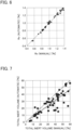
FIG. 6 is a relationship diagram between Ro (manual) and Ro (automatic). The coefficient of determination R2 = 0.95 and the error standard deviation RMSE = 0.03% were found, and thus Ro (automatic) was equivalent to Ro (manual). -
FIG. 7 is a relationship diagram between the total inert amount (manual) and the total inert amount (automatic). The coefficient of determination R2 = 0.2 and the error standard deviation RMSE = 10% were found, and thus the total inert amount (automatic) tended to be underestimated in comparison with the total inert amount (manual). - In general, it is known that semi-fusinite belonging to inertinite has an intermediate property between vitrinite and inertinite.
- Since the reflectance of semi-fusinite also indicates an intermediate value between those of vitrinite and inertinite, it is difficult to strictly classify semi-fusinite only by the magnitude of the reflectance value.
-
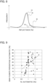
FIG. 8 is a reflectance histogram of one coal particle, which histogram illustrates a semi-fusinite reflectance. InFIG. 8 , thenormal distribution 16 is fitted to thereflectance histogram 15 of one coal particle, and themaximum value 18 of the vitrinite reflectance is also indicated. - Furthermore,
FIG. 8 illustrates a semi-fusinite reflectance 19 (a histogram of the semi-fusinite reflectance). - As illustrated in
FIG. 8 , the vitrinite reflectance range includes many semi-fusinite reflectances. In this case, since semi-fusinite belonging to inertinite is erroneously recognized as vitrinite, the total inert amount (automatic) is underestimated in comparison with the total inert amount (manual), as illustrated inFIG. 7 . The present inventors considered as described above. - Accordingly, the present inventors obtained the ratio (unit:%) of semi-fusinite by the conventional method as in the case of the total inert amount. Hereinafter, this may be referred to as a "semi-fusinite ratio (manual)".
-
FIG. 9 is a relationship diagram between Ro (automatic) and the semi-fusinite ratio (manual). - There is a correlation of the coefficient of determination R2 = 0.3 between Ro (automatic) and the semi-fusinite ratio (manual), and as illustrated in
FIG. 9 , the semi-fusinite ratio (manual) increases as Ro (automatic) rises. - Based on
FIG. 9 as described above, the present inventor considered that the influence of erroneously recognizing semi-fusinite as vitrinite when obtaining the total inert amount (automatic) can be corrected using Ro (automatic). - The present inventors performed multiple regression analysis on the total inert amount (manual) based on the following formula using two explanatory variables, Ro (automatic) and total inert amount (automatic).
Total inert amount (manual) = {a × total inert amount (automatic)} + (b × Ro (automatic)} + c - The multiple regression coefficients were a = 0.92, b = 24.1, and c = -15.9.
- The present inventors corrected the total inert amount (automatic) using the multiple regression coefficients obtained by the multiple regression analysis.
- Specifically, a corrected total inert amount (automatic) was obtained based on the following formula.
Corrected total inert amount (automatic) = {a × total inert amount (automatic)} + {b × Ro (automatic)} + c -
FIG. 10 is a relationship diagram between the total inert volume (manual) and the corrected total inert amount (automatic). The coefficient of determination R2 = 0.9 and the error standard deviation RMSE = 4% were found, and thus the corrected total inert amount (automatic) was equivalent to the total inert amount (manual). - If the total inert amount (manual) is more accurate than the total inert amount (automatic), it can be said that the corrected total inert amount (automatic) obtained by the correction using the multiple regression coefficient is also accurate.
- Therefore, the
correction unit 5 of thecoal analyzer 1 determines and retains the multiple regression coefficient in advance. - Then, the total inert amount is corrected using the multiple regression coefficient as well as Ro (automatic) and the total inert amount (automatic) calculated by the calculation unit 4 (step S113).
- Through such correction, the finally obtained total inert amount can be made more accurate.
- Note that the explanatory variables in the multiple regression analysis are not limited to the two, i.e., Ro (automatic) and the total inert amount (automatic). Other information that can be acquired from the
surface image 8 may be further added as an explanatory variable. - Coke is produced from coal with various brands blended according to its product indexes.
- That is, a plurality of types of coals are blended to prepare mixed coal, and the prepared mixed coal is calcined in a coke oven or the like to obtain coke.
- At this time, it is preferable to identify the total inert amount of at least part of the coal to be blended using the coal analysis method of the present embodiment described above.
- As described above, according to the coal analysis method of the present embodiment, the total inert amount can be easily obtained and the time can be shortened, and thus the preparation of mixed coal and coke production can also be simplified and expedited as a whole. In addition, the obtained total inert amount can be immediately reflected in coal blending calculation or the like.
-
- 1: coal analyzer
- 2: image acquisition unit
- 3: identification unit
- 4: calculation unit
- 5: correction unit
- 6: microscope
- 7: coal sample
- 8: surface image
- 9 (9a, 9b, 9c): coal particle
- 10: resin
- 11: vitrinite
- 12: inert
- 13: minimum threshold in vitrinite reflectance range
- 14: maximum threshold in vitrinite reflectance range
- 15: reflectance histogram of one coal particle
- 16: normal distribution
- 17: minimum value of vitrinite reflectance
- 18: maximum value of vitrinite reflectance
- 19: semi-fusinite reflectance
Claims (16)
- A coal analyzer comprising:an image acquisition unit that acquires a surface image of a coal sample;an identification unit that identifies a microstructural component group included in the surface image; anda calculation unit that calculates a ratio of at least one of the microstructural component groups.
- The coal analyzer according to claim 1, wherein the identification unit identifies the microstructural component group based on a reflectance of the microstructural component group.
- The coal analyzer according to claim 1 or 2, wherein the calculation unit calculates an average reflectance Ro of vitrinite, which is one of the microstructural component groups.
- The coal analyzer according to any one of claims 1 to 3, wherein the calculation unit calculates a total inert amount that is a ratio of inertinite among the microstructural component groups.
- The coal analyzer according to claim 4, further comprising a correction unit that corrects the total inert amount.
- The coal analyzer according to claim 5,wherein the calculation unit calculates an average reflectance Ro of vitrinite, which is one of the microstructural component groups, andthe correction unit corrects the total inert amount using the total inert amount and the average reflectance Ro of vitrinite.
- The coal analyzer according to claim 6, wherein the correction unit corrects the total inert amount using a multiple regression coefficient that is determined in advance, with the total inert amount and the average reflectance Ro of vitrinite as variables.
- A coal analysis method comprising:acquiring a surface image of a coal sample;identifying a microstructural component group included in the surface image; andcalculating a ratio of at least one of the microstructural component groups.
- The coal analysis method according to claim 8, further comprising identifying the microstructural component group based on a reflectance of the microstructural component group.
- The coal analysis method according to claim 8 or 9, further comprising calculating an average reflectance Ro of vitrinite, which is one of the microstructural component groups.
- The coal analysis method according to any one of claims 8 to 10, further comprising calculating a total inert amount that is a ratio of inertinite among the microstructural component groups.
- The coal analysis method according to claim 11, further comprising correcting the total inert amount.
- The coal analysis method according to claim 12, further comprising:calculating an average reflectance Ro of vitrinite, which is one of the microstructural component groups; andcorrecting the total inert amount using the total inert amount and the average reflectance Ro of vitrinite.
- The coal analysis method according to claim 13, further comprising correcting the total inert amount using a multiple regression coefficient that is determined in advance, with the total inert amount and the average reflectance Ro of vitrinite as variables.
- A mixed coal preparation method comprising:blending multiple types of coals to prepare mixed coal; andidentifying a total inert amount of at least part of the coal using the method according to any one of claims 8 to 14.
- A coke production method comprising using the mixed coal prepared by the method according to claim 15 to obtain coke.
Applications Claiming Priority (2)
| Application Number | Priority Date | Filing Date | Title |
|---|---|---|---|
| JP2021161012 | 2021-09-30 | ||
| PCT/JP2022/034999 WO2023054065A1 (en) | 2021-09-30 | 2022-09-20 | Coal analyzer, coal analysis method, mixed coal preparation method, and coke production method |
Publications (2)
| Publication Number | Publication Date |
|---|---|
| EP4394353A1 true EP4394353A1 (en) | 2024-07-03 |
| EP4394353A4 EP4394353A4 (en) | 2025-01-22 |
Family
ID=85782548
Family Applications (1)
| Application Number | Title | Priority Date | Filing Date |
|---|---|---|---|
| EP22875935.3A Pending EP4394353A4 (en) | 2021-09-30 | 2022-09-20 | COAL ANALYSIS DEVICE, COAL ANALYSIS METHOD, MIXED COAL PRODUCTION METHOD AND COKE PRODUCTION METHOD |
Country Status (7)
| Country | Link |
|---|---|
| US (1) | US20250116602A1 (en) |
| EP (1) | EP4394353A4 (en) |
| JP (1) | JP7405303B2 (en) |
| AU (1) | AU2022355586B2 (en) |
| CA (1) | CA3233032A1 (en) |
| TW (1) | TWI828344B (en) |
| WO (1) | WO2023054065A1 (en) |
Families Citing this family (1)
| Publication number | Priority date | Publication date | Assignee | Title |
|---|---|---|---|---|
| CN115950858B (en) * | 2022-12-01 | 2025-06-24 | 中煤科工智能储装技术有限公司 | Water-coal identification method based on multi-line laser radar scanning |
Family Cites Families (15)
| Publication number | Priority date | Publication date | Assignee | Title |
|---|---|---|---|---|
| JPS546237B2 (en) * | 1974-02-05 | 1979-03-26 | ||
| JPS5822940A (en) * | 1981-08-03 | 1983-02-10 | Mitsubishi Chem Ind Ltd | Method and apparatus for analyzing structure of coal |
| JPS5835442A (en) | 1981-08-27 | 1983-03-02 | Sumitomo Metal Ind Ltd | Automatic analyzing method for structure of coal |
| JPS58153144A (en) * | 1982-03-09 | 1983-09-12 | Nippon Kokan Kk <Nkk> | Apparatus for measuring organization composition ratio in massive material having a plurality of organizations with different reflectivities |
| JPH0219715Y2 (en) * | 1987-05-07 | 1990-05-30 | ||
| FR2713779B1 (en) * | 1993-12-10 | 1996-03-08 | Lorraine Laminage | Automatic process of maceral analysis and determination of the reflecting power of vitrinite in coals. |
| JP2005338011A (en) * | 2004-05-31 | 2005-12-08 | Jfe Steel Kk | Coal analysis method and coal quality control method |
| JP4438532B2 (en) * | 2004-06-30 | 2010-03-24 | Jfeスチール株式会社 | Coke and method for producing coke |
| CN102297850B (en) * | 2010-06-22 | 2014-03-19 | 宝山钢铁股份有限公司 | Digital automatic coal rock component measuring method |
| CN102928340A (en) * | 2012-10-19 | 2013-02-13 | 煤炭科学研究总院 | Image analysis-based method and special equipment for simultaneously determining content of maceral and vitrinite reflectance of coal |
| JP6342280B2 (en) * | 2014-09-25 | 2018-06-13 | 関西熱化学株式会社 | Method, apparatus and computer program for identifying high intensity components in coal. |
| CN111160064B (en) * | 2018-11-06 | 2023-05-02 | 煤炭科学技术研究院有限公司 | Identification method of coal rock composition |
| CN111879732B (en) * | 2020-08-17 | 2024-01-12 | 山西阳光焦化集团股份有限公司 | Method for simply and quantitatively measuring vitrinite content in coal |
| CN112132078A (en) * | 2020-09-29 | 2020-12-25 | 三一重型装备有限公司 | A Coal-Rock Interface Recognition System Based on Image and Thermal Imaging Tracking |
| CN112881306A (en) * | 2021-01-15 | 2021-06-01 | 吉林大学 | Hyperspectral image-based method for rapidly detecting ash content of coal |
-
2022
- 2022-09-20 WO PCT/JP2022/034999 patent/WO2023054065A1/en not_active Ceased
- 2022-09-20 CA CA3233032A patent/CA3233032A1/en active Pending
- 2022-09-20 AU AU2022355586A patent/AU2022355586B2/en active Active
- 2022-09-20 US US18/695,923 patent/US20250116602A1/en active Pending
- 2022-09-20 EP EP22875935.3A patent/EP4394353A4/en active Pending
- 2022-09-20 JP JP2023507326A patent/JP7405303B2/en active Active
- 2022-09-29 TW TW111137076A patent/TWI828344B/en active
Also Published As
| Publication number | Publication date |
|---|---|
| CA3233032A1 (en) | 2023-04-06 |
| JP7405303B2 (en) | 2023-12-26 |
| US20250116602A1 (en) | 2025-04-10 |
| EP4394353A4 (en) | 2025-01-22 |
| TWI828344B (en) | 2024-01-01 |
| AU2022355586B2 (en) | 2025-08-28 |
| TW202319745A (en) | 2023-05-16 |
| JPWO2023054065A1 (en) | 2023-04-06 |
| WO2023054065A1 (en) | 2023-04-06 |
| AU2022355586A1 (en) | 2024-04-11 |
Similar Documents
| Publication | Publication Date | Title |
|---|---|---|
| US6697509B2 (en) | Method and apparatus for scoring the uptake of markers in cells | |
| US9275441B2 (en) | Method for preparing quantitative video-microscopy and associated system | |
| US8611620B2 (en) | Advanced digital pathology and provisions for remote diagnostics | |
| US9418414B2 (en) | Image measurement apparatus, image measurement method and image measurement system | |
| CN108445010B (en) | Automatic optical detection method and device | |
| CN108520514A (en) | Printed circuit board electronics member device consistency detecting method based on computer vision | |
| JP7205399B2 (en) | Powder shape analysis method | |
| Van Zwanenberg et al. | Edge detection techniques for quantifying spatial imaging system performance and image quality | |
| CN111368844A (en) | Mineral particle automatic identification method based on BSE (sparse State image) diagram | |
| CN105678734B (en) | A kind of heterologous test image scaling method of image matching system | |
| JPH07253398A (en) | Maceral analysis for measuring content rate of vitrinite of coal | |
| US20250116602A1 (en) | Coal analyzer, coal analysis method, mixed coal preparation method, and coke production method | |
| CN106709501B (en) | Scene matching area selection and reference image optimization method of image matching system | |
| KR102338050B1 (en) | Method for analyzing atomic structure of stem images | |
| Widiastuti et al. | Digital image analysis using flatbed scanning system for purity testing of rice seed and confirmation by grow out test | |
| CN111060540A (en) | Automatic identification method for inclusion particles in automatic inclusion identification system | |
| JP2008268131A (en) | Grain quality evaluation method and grain leveling device used therefor | |
| CN116612331A (en) | Picture quality automatic detection method and device based on image processing and storage medium | |
| CN116642827A (en) | Large-scale fabric staining rating method and system based on hyperspectral imaging technology | |
| Bacus | Cervical cell recognition and morphometric grading by image analysis | |
| RU2797508C2 (en) | Method for automatic determination of resolution of digital optoelectronic systems and a test object of its implementation including line patterns with arcuate structure of elements | |
| CN113436147A (en) | Color resolution detection method of color imaging system based on image processing | |
| KR102613961B1 (en) | Determination method for cell zone of slide sample image smeared with bone-marrow and high magnification imaging method of the same cell zone | |
| Rustia et al. | Rapid tomato DUS trait analysis using an optimized mobile-based coarse-to-fine instance segmentation algorithm | |
| CN116630298A (en) | ISP objective index automatic analysis method and device based on image processing |
Legal Events
| Date | Code | Title | Description |
|---|---|---|---|
| STAA | Information on the status of an ep patent application or granted ep patent |
Free format text: STATUS: THE INTERNATIONAL PUBLICATION HAS BEEN MADE |
|
| PUAI | Public reference made under article 153(3) epc to a published international application that has entered the european phase |
Free format text: ORIGINAL CODE: 0009012 |
|
| STAA | Information on the status of an ep patent application or granted ep patent |
Free format text: STATUS: REQUEST FOR EXAMINATION WAS MADE |
|
| 17P | Request for examination filed |
Effective date: 20240328 |
|
| AK | Designated contracting states |
Kind code of ref document: A1 Designated state(s): AL AT BE BG CH CY CZ DE DK EE ES FI FR GB GR HR HU IE IS IT LI LT LU LV MC MK MT NL NO PL PT RO RS SE SI SK SM TR |
|
| DAV | Request for validation of the european patent (deleted) | ||
| DAX | Request for extension of the european patent (deleted) | ||
| A4 | Supplementary search report drawn up and despatched |
Effective date: 20250102 |
|
| RIC1 | Information provided on ipc code assigned before grant |
Ipc: G01N 1/36 20060101ALI20241218BHEP Ipc: G01N 1/28 20060101ALI20241218BHEP Ipc: G01N 21/27 20060101ALI20241218BHEP Ipc: C10B 45/00 20060101ALI20241218BHEP Ipc: G01N 21/84 20060101ALI20241218BHEP Ipc: G01N 21/55 20140101ALI20241218BHEP Ipc: G01N 1/32 20060101ALI20241218BHEP Ipc: G01N 21/47 20060101ALI20241218BHEP Ipc: C10B 57/04 20060101ALI20241218BHEP Ipc: G01N 21/17 20060101AFI20241218BHEP |