EP4394196A1 - Object holding structure - Google Patents
Object holding structure Download PDFInfo
- Publication number
- EP4394196A1 EP4394196A1 EP22889638.7A EP22889638A EP4394196A1 EP 4394196 A1 EP4394196 A1 EP 4394196A1 EP 22889638 A EP22889638 A EP 22889638A EP 4394196 A1 EP4394196 A1 EP 4394196A1
- Authority
- EP
- European Patent Office
- Prior art keywords
- ring
- end surface
- key plate
- holding structure
- hook portions
- Prior art date
- Legal status (The legal status is an assumption and is not a legal conclusion. Google has not performed a legal analysis and makes no representation as to the accuracy of the status listed.)
- Pending
Links
Images


Classifications
-
- F—MECHANICAL ENGINEERING; LIGHTING; HEATING; WEAPONS; BLASTING
- F16—ENGINEERING ELEMENTS AND UNITS; GENERAL MEASURES FOR PRODUCING AND MAINTAINING EFFECTIVE FUNCTIONING OF MACHINES OR INSTALLATIONS; THERMAL INSULATION IN GENERAL
- F16C—SHAFTS; FLEXIBLE SHAFTS; ELEMENTS OR CRANKSHAFT MECHANISMS; ROTARY BODIES OTHER THAN GEARING ELEMENTS; BEARINGS
- F16C35/00—Rigid support of bearing units; Housings, e.g. caps, covers
- F16C35/04—Rigid support of bearing units; Housings, e.g. caps, covers in the case of ball or roller bearings
- F16C35/06—Mounting or dismounting of ball or roller bearings; Fixing them onto shaft or in housing
- F16C35/063—Fixing them on the shaft
-
- F—MECHANICAL ENGINEERING; LIGHTING; HEATING; WEAPONS; BLASTING
- F16—ENGINEERING ELEMENTS AND UNITS; GENERAL MEASURES FOR PRODUCING AND MAINTAINING EFFECTIVE FUNCTIONING OF MACHINES OR INSTALLATIONS; THERMAL INSULATION IN GENERAL
- F16B—DEVICES FOR FASTENING OR SECURING CONSTRUCTIONAL ELEMENTS OR MACHINE PARTS TOGETHER, e.g. NAILS, BOLTS, CIRCLIPS, CLAMPS, CLIPS OR WEDGES; JOINTS OR JOINTING
- F16B39/00—Locking of screws, bolts or nuts
-
- F—MECHANICAL ENGINEERING; LIGHTING; HEATING; WEAPONS; BLASTING
- F16—ENGINEERING ELEMENTS AND UNITS; GENERAL MEASURES FOR PRODUCING AND MAINTAINING EFFECTIVE FUNCTIONING OF MACHINES OR INSTALLATIONS; THERMAL INSULATION IN GENERAL
- F16C—SHAFTS; FLEXIBLE SHAFTS; ELEMENTS OR CRANKSHAFT MECHANISMS; ROTARY BODIES OTHER THAN GEARING ELEMENTS; BEARINGS
- F16C35/00—Rigid support of bearing units; Housings, e.g. caps, covers
- F16C35/04—Rigid support of bearing units; Housings, e.g. caps, covers in the case of ball or roller bearings
- F16C35/06—Mounting or dismounting of ball or roller bearings; Fixing them onto shaft or in housing
- F16C35/067—Fixing them in a housing
-
- F—MECHANICAL ENGINEERING; LIGHTING; HEATING; WEAPONS; BLASTING
- F16—ENGINEERING ELEMENTS AND UNITS; GENERAL MEASURES FOR PRODUCING AND MAINTAINING EFFECTIVE FUNCTIONING OF MACHINES OR INSTALLATIONS; THERMAL INSULATION IN GENERAL
- F16C—SHAFTS; FLEXIBLE SHAFTS; ELEMENTS OR CRANKSHAFT MECHANISMS; ROTARY BODIES OTHER THAN GEARING ELEMENTS; BEARINGS
- F16C19/00—Bearings with rolling contact, for exclusively rotary movement
- F16C19/02—Bearings with rolling contact, for exclusively rotary movement with bearing balls essentially of the same size in one or more circular rows
- F16C19/04—Bearings with rolling contact, for exclusively rotary movement with bearing balls essentially of the same size in one or more circular rows for radial load mainly
- F16C19/06—Bearings with rolling contact, for exclusively rotary movement with bearing balls essentially of the same size in one or more circular rows for radial load mainly with a single row or balls
-
- F—MECHANICAL ENGINEERING; LIGHTING; HEATING; WEAPONS; BLASTING
- F16—ENGINEERING ELEMENTS AND UNITS; GENERAL MEASURES FOR PRODUCING AND MAINTAINING EFFECTIVE FUNCTIONING OF MACHINES OR INSTALLATIONS; THERMAL INSULATION IN GENERAL
- F16C—SHAFTS; FLEXIBLE SHAFTS; ELEMENTS OR CRANKSHAFT MECHANISMS; ROTARY BODIES OTHER THAN GEARING ELEMENTS; BEARINGS
- F16C2300/00—Application independent of particular apparatuses
- F16C2300/20—Application independent of particular apparatuses related to type of movement
- F16C2300/22—High-speed rotation
-
- F—MECHANICAL ENGINEERING; LIGHTING; HEATING; WEAPONS; BLASTING
- F16—ENGINEERING ELEMENTS AND UNITS; GENERAL MEASURES FOR PRODUCING AND MAINTAINING EFFECTIVE FUNCTIONING OF MACHINES OR INSTALLATIONS; THERMAL INSULATION IN GENERAL
- F16C—SHAFTS; FLEXIBLE SHAFTS; ELEMENTS OR CRANKSHAFT MECHANISMS; ROTARY BODIES OTHER THAN GEARING ELEMENTS; BEARINGS
- F16C2326/00—Articles relating to transporting
- F16C2326/43—Aeroplanes; Helicopters
-
- F—MECHANICAL ENGINEERING; LIGHTING; HEATING; WEAPONS; BLASTING
- F16—ENGINEERING ELEMENTS AND UNITS; GENERAL MEASURES FOR PRODUCING AND MAINTAINING EFFECTIVE FUNCTIONING OF MACHINES OR INSTALLATIONS; THERMAL INSULATION IN GENERAL
- F16C—SHAFTS; FLEXIBLE SHAFTS; ELEMENTS OR CRANKSHAFT MECHANISMS; ROTARY BODIES OTHER THAN GEARING ELEMENTS; BEARINGS
- F16C2360/00—Engines or pumps
- F16C2360/23—Gas turbine engines
Definitions
- the present disclosure relates to a structure for holding an object such as a bearing.
- Patent Literature 1 discloses a bearing holding structure applied in an aircraft jet engine.
- An inner ring of the bearing is installed on an outer peripheral surface of an extension which integrally rotates with a shaft.
- the inner ring is held by being pressed forward with a spanner nut.
- an outer ring of the bearing is installed on an inner peripheral surface of a bearing housing.
- a retainer is provided in front of the outer ring.
- the retainer is screwed into the bearing housing. Thereby, the retainer is moved backward and pushes the outer ring backward.
- the retainer has a hook portion. The retainer is fixed to the bearing housing with a bolt while the hook portion is hung on the bearing housing.
- the retainer is fixed to an outer member such as a bearing housing with a combination of a hook portion and a bolt.
- an outer member such as a bearing housing with a combination of a hook portion and a bolt.
- this mechanism cannot be adopted.
- the bearing holding structure disclosed in Patent Literatures 2 and 3 such an increase in size can be avoided.
- the strength may be reduced due to the hole machining of the inner member, it is not suitable to be applied to a rotating body such as a shaft which is excessively loaded by centrifugal force during operation.
- the present disclosure has been made in view of the above-mentioned circumstances, and is intended to provide an object holding structure capable of preventing misassembly while suppressing excessive increase in the number and weight of parts.
- An object holding structure includes: an inner member extending in an axial direction, including: an end surface, a first clamping surface located radially outward of the end surface when viewed from the axial direction, and hook portions arranged in a circumferential direction at intervals on the end surface and having claw portions extending radially inwardly; an outer member located radially outward of the inner member and movably provided in the axial direction relative to the inner member, the outer member including an end surface and a second clamping surface facing the first clamping surface through an object; a key plate contactable to each of the end surface of the inner member and the end surface of the outer member; a retaining ring held between the key plate and the claw portions of the hook portions; and wherein the key plate includes: a first ring facing the end surface of the outer member; a second ring provided radially inward of the hook portions when viewed from the axial direction; inner tabs located between the hook portions in the circumferential direction and linking the first ring and the
- An object holding structure includes: an outer member extending in an axial direction, including: an end surface, and a first clamping surface located radially inward of the end surface when viewed from the axial direction; an inner member located radially inward of the outer member and movably provided in the axial direction relative to the outer member, the inner member including: an end surface, a second clamping surface facing the first clamping surface through an object, and hook portions arranged in a circumferential direction at intervals on the end surface and having claw portions extending radially inwardly; a key plate contactable to each of the end surface of the inner member and the end surface of the outer member; a retaining ring held between the key plate and the claw portions of the hook portions; and wherein the key plate includes: a first ring facing the end surface of the outer member; a second ring provided radially inward of the hook portions when viewed from the axial direction; inner tabs located between the hook portions in the circumferential direction and linking the first ring
- the second ring may include an inclined portion provided at an inner edge portion located radially inwardly.
- the inclined portion may be formed in an annular shape extending in the circumferential direction, and the inclined portion may be inclined to a side where the retaining ring is located with respect to a virtual plane including the first ring so that a distance from the virtual plane increases as the inclined portion approaches a center of the second ring.
- the inclined portion may be entirely formed in the second ring.
- the second ring may include a tongue portion provided at an inner edge portion located radially inwardly.
- the tongue portion may be formed in an annular shape extending in the circumferential direction, and the tongue portion may protrude from the inner edge portion on a side where the retaining ring is located relative to the virtual plane so that the tongue portion gets away from a virtual plane including the first ring.
- Each of the inner tabs may include a pair of flanges obliquely extending from both sides thereof in the circumferential direction toward the end surface of the outer member.
- the key plate may be formed of a single metal plate.
- Each of the inner tabs may include a pair of flanges obliquely extending from edges on both sides in the circumferential direction to a side opposite to the side where the retaining ring is located relative to the virtual plane including the first ring.
- the outer member may include projections on the end surface of the outer member, located radially outward of the first ring of the key plate.
- the key plate may include outer tabs located radially outward of the first ring.
- the projections may be arranged at intervals in the circumferential direction. Each of the outer tabs may extend radially outward from the first ring at least to a position between the projections.
- the object holding structure 10A is configured to hold an annular or a disk-shaped object by regulating the axial movement of the object.
- the object holding structure 10A is provided at the end of a shaft and is used to hold a bearing 60 that rotatably supports the shaft.
- a Z-axis is defined as a reference axis of the entire object holding structure 10A, and its extension direction is referred to as the axial direction AD.
- a circumferential direction CD and a radial direction RD are defined with reference to the Z-axis.
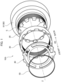
- FIG. 1 is an exploded perspective view showing an example of the object holding structure 10A according to the first embodiment.
- a diagonally forward left side of FIG. 1 is defined as "front”
- a diagonally backward right side of FIG. 1 is defined as "back”.
- a spacer S shown in FIG. 1 can be appropriately omitted depending on the specification.
- the object holding structure 10A holds an inner ring 61 of the bearing 60 as an example of the object to be held.
- the object holding structure 10A includes a shaft 20 as an inner member, a lock nut 30 as an outer member, a key plate 40, and a retaining ring 50.
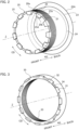
- FIG. 2 is a perspective view showing the shaft 20 as an example of an inner member according to the present embodiment.
- the shaft 20 is a hollow rod-shaped member (i.e., a tubular member) centered on the Z-axis and extends in the axial direction AD.
- the shaft 20 is rotated by a rotary driving device such as a turbine.
- the shaft 20 has an end surface 21 facing forward and an annular projection 22A (stopper).
- the annular projection 22A protrudes radially outward from the outer peripheral surface 24 of the shaft 20 and is formed in an annular shape centered on the Z-axis.
- the annular projection 22A includes a first clamping surface 23 facing forward (i.e., facing the object to be held).
- the first clamping surface 23 is positioned radially outward of the end surface 21 when viewed from the axial direction AD.
- a step may be provided on the outer peripheral surface 24 of the shaft 20 so that the diameter (outer diameter) of the outer peripheral surface 24 of the shaft 20 is decreased at the front end 20a of the shaft 20, and the step may form the first clamping surface 23.
- the inner ring 61 of the bearing 60 is attached to the shaft 20 from the end surface 21 side, the inner ring 61 is restricted in further movement along the Z-axis by abutting on the first clamping surface 23.
- the lock nut 30 is screwed to the end 20a of the shaft 20 in a state where the bearing 60 is attached to the shaft 20.
- the lock nut 30 is positioned radially outward of the shaft 20 and is movably provided in the axial direction AD with respect to the shaft 20 by its own rotation.
- the shaft 20 includes hook portions 25.
- the hook portions 25 are provided on the end surface 21 at intervals in the circumferential direction CD.
- a tip of each hook portion 25 has a shape which is curved radially inwardly.
- each hook portion 25 has a leg portion 25a projecting forward from the end surface 21 and a claw portion 25b extending radially inward from the leg portion 25a (see FIG. 8 ) .
- the length of the leg portion 25a along the axial direction AD has a value such that the distance between the inner surface 25c of the claw portion 25b and the end surface 21 along the axial direction AD is equal to or greater than a thickness of the retaining ring 50 and the inner tab 43 of the key plate 40 that are overlapped (see FIG. 8 ). Since such a length is set to the leg portion 25a, the retaining ring 50 and the key plate 40 can be easily attached to the shaft 20. In addition, excessive pressing by the claw portion 25b against both of them can be avoided to prevent the occurrence of deformation.
- the length of the claw portion 25b along the radial direction RD has a value such that the retaining ring 50 can be accommodated inside the hook portions 25 and the claw portions 25b do not interfere with the second ring 42 of the key plate 40 when the key plate 40 is mounted. Therefore, when viewed from the axial direction AD, the tips 25d of the claw portions 25b are located radially outward of an outer edge 42b of the second ring 42 (see FIG. 7 ).
- FIG. 3 is a perspective view showing an example of the lock nut 30 according to the present embodiment.
- the lock nut 30 is an annular member having an annular cross section centered on the Z-axis and extending in the axial direction AD.
- the lock nut 30 extends in the axial direction AD by a predetermined length so that the inner ring 61 of the bearing 60 is held between the lock nut 30 and the shaft 20 in the axial direction AD.
- the lock nut 30 includes an end surface 31 facing forward and a second clamping surface 33 facing backward (i.e., facing the object to be held). When viewed from the axial direction AD, the end surface 31 and the second clamping surface 33 overlap each other.
- the second clamping surface 33 faces the first clamping surface 23 through an inner ring 61 or the like of the bearing 60.
- the lock nut 30 is provided with an attachment hole 32 into which the shaft 20 is inserted and screwed.
- the attachment hole 32 is formed around the Z-axis as the central axis thereof and extends from the second clamping surface 33 to the end surface 31. That is, the attachment hole 32 penetrates between the end surface 31 and the second clamping surface 33.
- the second clamping surface 33 abuts against the inner ring 61 (or the spacer S if the spacer S is provided) . Thereby, the movement of the inner ring 61 forward and backward is restricted and held.
- the structure such as the spacer S may be positioned between the first clamping surface 23 and the inner ring 61, or between the second clamping surface 33 and the inner ring 61.
- the lock nut 30 may include projections 34.
- the projections 34 are positioned radially outward of the first ring 41 of the key plate 40 on the end surface 21.
- the projections 34 project forward from the end surface 31 and are arranged at intervals in the circumferential direction CD on the same circle centered at a point on the Z-axis. The intervals in the circumferential direction are longer than the widths of the outer tabs 44 along the circumferential direction CD, which are provided on the key plate 40.
- FIG. 6 is a cross-sectional view for explaining the assembly of the object holding structure 10A, wherein (a) shows a state before assembly and (b) shows a state after assembly.
- FIG. 7 is a front view of the object holding structure 10A after assembly.
- FIG. 8(a) is a cross-sectional view along the line A-A in FIG. 7
- FIG. 8(b) is a cross-sectional view along the line B-B in FIG. 7 .
- the retaining ring 50 when viewed from the circumferential CD, the retaining ring 50 is positioned between the claw portions 25b of the hook portions 25 and the key plate 40, and is held by the hook portions 25. Consequently, the key plate 40 is prevented from falling off.
- FIG. 10 is a cross-sectional view for explaining the assembly of the object holding structure 10B according to the second embodiment of the present disclosure, wherein (a) shows a state before assembly and (b) shows a state after assembly.
- FIG. 11 is a cross-sectional view showing a modification of the object holding structure 10B according to the second embodiment, wherein (a) shows a state before assembly and (b) shows a state after assembly.
- the object holding structure 10B according to the present embodiment holds the outer ring 62 of the bearing 60 as an example of an object to be held.
- the object holding structure 10B includes a shaft 20 as an outer member, a lock nut 30 as an inner member, a key plate 40, and a retaining ring 50.
- the shaft 20 is a rod-shaped member (i.e., a tubular member) extending with the Z-axis as the central axis.
- an attachment hole 26 is formed at the end 20a of the shaft 20.
- An outer ring 62 of a bearing 60 as an object to be held is fitted with the attachment hole 26, and a lock nut 30 is screwed into the attachment hole 26.
- the lock nut 30 With the bearing 60 attached to the shaft 20, the lock nut 30 is screwed into the attachment hole 26 of the shaft 20.
- the lock nut 30 is positioned radially inward of the shaft 20 and is provided movably in the axial direction AD with respect to the shaft 20.
- the key plate 40 according to the present embodiment also has a second ring 42 provided radially inward of the hook portions 35 when viewed from the axial direction AD. Therefore, as described above, when the retaining ring 50 is attached, even if a part of the retaining ring enters an area surrounded by the second ring 42, the second ring 42 immediately contacts the retaining ring 50 and further entry is restricted. Therefore, it is possible to prevent mis-attachment of the retaining ring 50 and stably hold the inner ring 61 of the bearing 60 as an object to be held while suppressing the looseness of the lock nut 30.
- FIG. 12 is a view showing several modified examples of the key plate 40 according to each embodiment, wherein (a) is a cross-sectional view of the first modified example along the axial direction, (b) is a cross-sectional view of the second modified example along the axial direction, (c) is a front view showing a part of the third modified example, and (d) is a cross-sectional view of the third modified example along the circumferential direction.
Landscapes
- Engineering & Computer Science (AREA)
- General Engineering & Computer Science (AREA)
- Mechanical Engineering (AREA)
- Snaps, Bayonet Connections, Set Pins, And Snap Rings (AREA)
- Support Of The Bearing (AREA)
- Mounting Of Bearings Or Others (AREA)
Abstract
Description
- The present disclosure relates to a structure for holding an object such as a bearing.
-
Patent Literature 1 discloses a bearing holding structure applied in an aircraft jet engine. An inner ring of the bearing is installed on an outer peripheral surface of an extension which integrally rotates with a shaft. The inner ring is held by being pressed forward with a spanner nut. On the other hand, an outer ring of the bearing is installed on an inner peripheral surface of a bearing housing. - A retainer is provided in front of the outer ring. The retainer is screwed into the bearing housing. Thereby, the retainer is moved backward and pushes the outer ring backward. The retainer has a hook portion. The retainer is fixed to the bearing housing with a bolt while the hook portion is hung on the bearing housing.
-
- Patent Literature 1:
US 2009/0034896 A1 - Patent Literature 2:
US 2021/0048065 A1 - Patent Literature 3:
US 2018/0283456 A1 - Generally speaking, as shown in
Patent Literature 1, the retainer is fixed to an outer member such as a bearing housing with a combination of a hook portion and a bolt. In order to provide the hook portion to the retainer, it is necessary to partially increase the diameter of the outer member. However, if it is impossible to increase the sizes of the retainer and the outer member due to the influence of peripheral components, this mechanism cannot be adopted. In the bearing holding structure disclosed in Patent Literatures 2 and 3, such an increase in size can be avoided. However, since the number of parts increases instead, an increase in weight and cumbersome assembly are concerned. In addition, since the strength may be reduced due to the hole machining of the inner member, it is not suitable to be applied to a rotating body such as a shaft which is excessively loaded by centrifugal force during operation. - The present disclosure has been made in view of the above-mentioned circumstances, and is intended to provide an object holding structure capable of preventing misassembly while suppressing excessive increase in the number and weight of parts.
- An object holding structure according to the first aspect of the present disclosure includes: an inner member extending in an axial direction, including: an end surface, a first clamping surface located radially outward of the end surface when viewed from the axial direction, and hook portions arranged in a circumferential direction at intervals on the end surface and having claw portions extending radially inwardly; an outer member located radially outward of the inner member and movably provided in the axial direction relative to the inner member, the outer member including an end surface and a second clamping surface facing the first clamping surface through an object; a key plate contactable to each of the end surface of the inner member and the end surface of the outer member; a retaining ring held between the key plate and the claw portions of the hook portions; and wherein the key plate includes: a first ring facing the end surface of the outer member; a second ring provided radially inward of the hook portions when viewed from the axial direction; inner tabs located between the hook portions in the circumferential direction and linking the first ring and the second ring.
- An object holding structure according to the second aspect of the present disclosure includes: an outer member extending in an axial direction, including: an end surface, and a first clamping surface located radially inward of the end surface when viewed from the axial direction; an inner member located radially inward of the outer member and movably provided in the axial direction relative to the outer member, the inner member including: an end surface, a second clamping surface facing the first clamping surface through an object, and hook portions arranged in a circumferential direction at intervals on the end surface and having claw portions extending radially inwardly; a key plate contactable to each of the end surface of the inner member and the end surface of the outer member; a retaining ring held between the key plate and the claw portions of the hook portions; and wherein the key plate includes: a first ring facing the end surface of the outer member; a second ring provided radially inward of the hook portions when viewed from the axial direction; inner tabs located between the hook portions in the circumferential direction and linking the first ring and the second ring.
- The second ring may include an inclined portion provided at an inner edge portion located radially inwardly. The inclined portion may be formed in an annular shape extending in the circumferential direction, and the inclined portion may be inclined to a side where the retaining ring is located with respect to a virtual plane including the first ring so that a distance from the virtual plane increases as the inclined portion approaches a center of the second ring. The inclined portion may be entirely formed in the second ring.
- The second ring may include a tongue portion provided at an inner edge portion located radially inwardly. The tongue portion may be formed in an annular shape extending in the circumferential direction, and the tongue portion may protrude from the inner edge portion on a side where the retaining ring is located relative to the virtual plane so that the tongue portion gets away from a virtual plane including the first ring.
- Each of the inner tabs may include a pair of flanges obliquely extending from both sides thereof in the circumferential direction toward the end surface of the outer member. The key plate may be formed of a single metal plate. Each of the inner tabs may include a pair of flanges obliquely extending from edges on both sides in the circumferential direction to a side opposite to the side where the retaining ring is located relative to the virtual plane including the first ring.
- The outer member may include projections on the end surface of the outer member, located radially outward of the first ring of the key plate. The key plate may include outer tabs located radially outward of the first ring. The projections may be arranged at intervals in the circumferential direction. Each of the outer tabs may extend radially outward from the first ring at least to a position between the projections.
- According to the present disclosure, it is possible to provide an object holding structure capable of preventing misassembly while suppressing excessive increase in the number and weight of parts.
-
-
FIG. 1 is an exploded perspective view showing an example of an object holding structure according to the first embodiment of the present disclosure. -
FIG. 2 is a perspective view showing a shaft as an example of an inner member according to the first embodiment of the present disclosure. -
FIG. 3 is a perspective view showing an example of a lock nut according to the first embodiment of the present disclosure. -
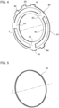
FIG. 4 is a perspective view showing an example of a key plate according to the first embodiment of the present disclosure. -
FIG. 5 is a perspective view showing an example of a retaining ring according to the first embodiment of the present disclosure. -
FIG. 6 is a cross-sectional view for explaining an assembly of the object holding structure according to the first embodiment of the present disclosure, wherein (a) shows a state before assembly and (b) shows a state after assembly. -
FIG. 7 is a front view of the object holding structure according to the first embodiment of the present disclosure after assembly. -
FIG. 8 is a partial cross-sectional view of the object holding structure shown inFIG. 7 , wherein (a) is a cross-sectional view along the line A-A inFIG. 7 and (b) is a cross-sectional view along the line B-B inFIG. 7 . -
FIG. 9 is a view showing the positional relationship between the retaining ring and the key plate in the hook portion when viewed from the radial direction, wherein (a) shows a state in which the retaining ring is properly assembled and (b) shows a state in which the retaining ring wound be improperly assembled. -
FIG. 10 is a cross-sectional view for explaining the assembly of the object holding structure according to the second embodiment of the present disclosure, wherein (a) shows a state before assembly and (b) shows a state after assembly. -
FIG. 11 is a cross-sectional view showing a modified example of the object holding structure according to the second embodiment, wherein (a) shows a state before assembly and (b) shows a state after assembly. -
FIG. 12 is a view showing several modified examples of the key plate according to the embodiments of the present disclosure, wherein (a) is a cross-sectional view of the first modified example along the axial direction, (b) is a cross-sectional view of the second modified example along the axial direction, (c) is a front view showing a part of the third modified example, and (d) is a cross-sectional view of the third modified example along the circumferential direction. - Hereinafter, an
object holding structure 10A according to embodiments of the present disclosure will be described. The same reference numerals will be used for common parts in each figure, and duplicate descriptions therefor will be omitted. Theobject holding structure 10A is configured to hold an annular or a disk-shaped object by regulating the axial movement of the object. For example, as described below, theobject holding structure 10A is provided at the end of a shaft and is used to hold abearing 60 that rotatably supports the shaft. Hereinafter, for convenience of explanation, a Z-axis is defined as a reference axis of the entireobject holding structure 10A, and its extension direction is referred to as the axial direction AD. Further, a circumferential direction CD and a radial direction RD are defined with reference to the Z-axis. - The
object holding structure 10A according to the first embodiment will be described below.FIG. 1 is an exploded perspective view showing an example of theobject holding structure 10A according to the first embodiment. For convenience of explanation, a diagonally forward left side ofFIG. 1 is defined as "front", and a diagonally backward right side ofFIG. 1 is defined as "back". Note that a spacer S shown inFIG. 1 can be appropriately omitted depending on the specification. - The
object holding structure 10A according to the present embodiment holds aninner ring 61 of thebearing 60 as an example of the object to be held. As shown inFIG. 1 , theobject holding structure 10A includes ashaft 20 as an inner member, alock nut 30 as an outer member, akey plate 40, and a retainingring 50. -
FIG. 2 is a perspective view showing theshaft 20 as an example of an inner member according to the present embodiment. Theshaft 20 is a hollow rod-shaped member (i.e., a tubular member) centered on the Z-axis and extends in the axial direction AD. Theshaft 20 is rotated by a rotary driving device such as a turbine. Theshaft 20 has anend surface 21 facing forward and anannular projection 22A (stopper). Theannular projection 22A protrudes radially outward from the outerperipheral surface 24 of theshaft 20 and is formed in an annular shape centered on the Z-axis. - The
annular projection 22A includes afirst clamping surface 23 facing forward (i.e., facing the object to be held). Thefirst clamping surface 23 is positioned radially outward of theend surface 21 when viewed from the axial direction AD. Instead of providing theannular projection 22A, a step may be provided on the outerperipheral surface 24 of theshaft 20 so that the diameter (outer diameter) of the outerperipheral surface 24 of theshaft 20 is decreased at thefront end 20a of theshaft 20, and the step may form thefirst clamping surface 23. In either case, after theinner ring 61 of thebearing 60 is attached to theshaft 20 from theend surface 21 side, theinner ring 61 is restricted in further movement along the Z-axis by abutting on thefirst clamping surface 23. - The
lock nut 30 is screwed to theend 20a of theshaft 20 in a state where thebearing 60 is attached to theshaft 20. Thelock nut 30 is positioned radially outward of theshaft 20 and is movably provided in the axial direction AD with respect to theshaft 20 by its own rotation. - As shown in
FIG. 2 , theshaft 20 includeshook portions 25. Thehook portions 25 are provided on theend surface 21 at intervals in the circumferential direction CD. A tip of eachhook portion 25 has a shape which is curved radially inwardly. Specifically, eachhook portion 25 has aleg portion 25a projecting forward from theend surface 21 and aclaw portion 25b extending radially inward from theleg portion 25a (seeFIG. 8 ) . - The length of the
leg portion 25a along the axial direction AD has a value such that the distance between theinner surface 25c of theclaw portion 25b and theend surface 21 along the axial direction AD is equal to or greater than a thickness of the retainingring 50 and theinner tab 43 of thekey plate 40 that are overlapped (seeFIG. 8 ). Since such a length is set to theleg portion 25a, the retainingring 50 and thekey plate 40 can be easily attached to theshaft 20. In addition, excessive pressing by theclaw portion 25b against both of them can be avoided to prevent the occurrence of deformation. - The length of the
claw portion 25b along the radial direction RD has a value such that the retainingring 50 can be accommodated inside thehook portions 25 and theclaw portions 25b do not interfere with thesecond ring 42 of thekey plate 40 when thekey plate 40 is mounted. Therefore, when viewed from the axial direction AD, thetips 25d of theclaw portions 25b are located radially outward of anouter edge 42b of the second ring 42 (seeFIG. 7 ). -
FIG. 3 is a perspective view showing an example of thelock nut 30 according to the present embodiment. Thelock nut 30 is an annular member having an annular cross section centered on the Z-axis and extending in the axial direction AD. Thelock nut 30 extends in the axial direction AD by a predetermined length so that theinner ring 61 of thebearing 60 is held between thelock nut 30 and theshaft 20 in the axial direction AD. Thelock nut 30 includes anend surface 31 facing forward and asecond clamping surface 33 facing backward (i.e., facing the object to be held). When viewed from the axial direction AD, theend surface 31 and thesecond clamping surface 33 overlap each other. Thesecond clamping surface 33 faces thefirst clamping surface 23 through aninner ring 61 or the like of thebearing 60. - The
lock nut 30 is provided with anattachment hole 32 into which theshaft 20 is inserted and screwed. Theattachment hole 32 is formed around the Z-axis as the central axis thereof and extends from thesecond clamping surface 33 to theend surface 31. That is, theattachment hole 32 penetrates between theend surface 31 and thesecond clamping surface 33. - When the
lock nut 30 moves backward, thesecond clamping surface 33 abuts against the inner ring 61 (or the spacer S if the spacer S is provided) . Thereby, the movement of theinner ring 61 forward and backward is restricted and held. The structure such as the spacer S may be positioned between thefirst clamping surface 23 and theinner ring 61, or between thesecond clamping surface 33 and theinner ring 61. - The
lock nut 30 may includeprojections 34. Theprojections 34 are positioned radially outward of thefirst ring 41 of thekey plate 40 on theend surface 21. Theprojections 34 project forward from theend surface 31 and are arranged at intervals in the circumferential direction CD on the same circle centered at a point on the Z-axis. The intervals in the circumferential direction are longer than the widths of theouter tabs 44 along the circumferential direction CD, which are provided on thekey plate 40. -
FIG. 4 is a perspective view showing an example of thekey plate 40 according to the present embodiment. Thekey plate 40 is provided to be contactable with theend surface 21 of theshaft 20 and theend surface 31 of the lock nut 30 (seeFIG. 6 ). Thekey plate 40 includes afirst ring 41, asecond ring 42, andinner tabs 43. Thefirst ring 41, thesecond ring 42, and theinner tabs 43 all have the same thickness and are arranged on the same plane. Thus, thekey plate 40 may be formed of, for example, a single metal plate. In this case, a joining process such as welding between the components is not required, and easy manufacturing is possible. - The
first ring 41 faces theend surface 31 of thelock nut 30. Thesecond ring 42 is provided radially inward of thehook portions 25 when viewed from the axial direction AD. Theinner tabs 43 are located between thehook portions 25 in the circumferential direction CD and connect thefirst ring 41 and thesecond ring 42. The number ofinner tabs 43 is arbitrary as long as it does not affect the maintenance of the overall shape of thekey plate 40. - The
key plate 40 may includeouter tabs 44 disposed radially outward of thefirst ring 41. Theouter tabs 44 extend from the outer edge of thekey plate 40 to positions between mutually adjacent two of theprojections 34. The number ofouter tabs 44 is arbitrary. -
FIG. 5 is a perspective view showing an example of the retainingring 50 according to the present embodiment. The retainingring 50 is held between theclaw portions 25b ofhook portions 25 and thekey plate 40. Accordingly, the outer diameter and the inner diameter of the retainingring 50 are set so that the retainingring 50 overlaps theclaw portion 25b when viewed from the axial direction AD. The retainingring 50 is formed of a long and thin metal bar wire or the like from the viewpoint of weight reduction and allowing deformation of the radial direction RD during assembly. The retainingring 50 may be continuous to the circumferential direction CD as a so-called O-ring or may be interrupted in the middle thereof in the circumferential direction CD as a so-called C-ring. - Next, the assembly of the
object holding structure 10A will be described.FIG. 6 is a cross-sectional view for explaining the assembly of theobject holding structure 10A, wherein (a) shows a state before assembly and (b) shows a state after assembly.FIG. 7 is a front view of theobject holding structure 10A after assembly.FIG. 8(a) is a cross-sectional view along the line A-A inFIG. 7 , andFIG. 8(b) is a cross-sectional view along the line B-B inFIG. 7 . - First, the
inner ring 61 of thebearing 60 is attached to theshaft 20 and moved backward until it comes into contact with thefirst clamping surface 23. Next, thelock nut 30 is attached to theshaft 20 and screwed into theshaft 20. When thelock nut 30 is rotated, thelock nut 30 moves backward. Thelock nut 30 is rotated until thesecond clamping surface 33 of thelock nut 30 comes into contact with theinner ring 61 of thebearing 60. - Next, the posture of the
key plate 40 is adjusted so that thekey plate 40 faces each of theend surface 21 of theshaft 20 and theend surface 31 of thelock nut 30. In addition, the phase of thekey plate 40 with respect to the arrangement of thehook portions 25 is adjusted so that eachinner tab 43 of thekey plate 40 is positioned between two adjacent to each other among thehook portions 25. Thereafter, thekey plate 40 approaches until it comes into contact with each end surface. - When the
projections 34 are provided on theend surface 21 of thelock nut 30 and theouter tabs 44 are provided to thekey plate 40, thelock nut 30 may be slightly rotated such that theouter tabs 44 are located between mutually adjacent two of theprojections 34 during the phase adjustment described above. - Next, the retaining
ring 50 is attached to be housed inside thehook portions 25, and thereby the assembly is completed. At this time, as shown inFIG. 7 , thehook portions 25 penetrate thekey plate 40 through thefirst ring 41 and thesecond ring 42 of thekey plate 40. Further, eachinner tab 43 of thekey plate 40 is positioned between mutually adjacent two of thehook portions 25. Accordingly, thekey plate 40 is properly positioned relative to the arrangement of thehook portions 25, and the rotation of the circumferential CD of thekey plate 40 is restricted. - Further, as shown in
FIG. 8 , when viewed from the circumferential CD, the retainingring 50 is positioned between theclaw portions 25b of thehook portions 25 and thekey plate 40, and is held by thehook portions 25. Consequently, thekey plate 40 is prevented from falling off. -
FIG. 9 is a view showing the positional relationship between the retainingring 50 and thekey plate 40 in thehook portion 25 when viewed from the radial direction RD, wherein (a) shows a state in which the retainingring 50 is properly assembled and (b) shows a state in which the retainingring 50 wound be improperly assembled. - If the
lock nut 30 is loosened and moved forward due to a disturbance such as rotation or vibration of theshaft 20, thelock nut 30 comes in contact with thekey plate 40. The reaction force from thekey plate 40 caused by this contact suppresses the rotation of thelock nut 30 in the direction in which thelock nut 30 is loosened, and the unexpected movement of theinner ring 61 of thebearing 60 is also restricted. That is, thebearing 60 is stably held at theend 20a of theshaft 20. - When the
projections 34 are provided on theend surface 31 of thelock nut 30 and theouter tabs 44 are provided on thekey plate 40, any of theprojections 34 of thelock nut 30 come into contact with theouter tab 44 when thelock nut 30 is rotated in the loosening direction. The rotation of thekey plate 40 in the circumferential CD is restricted by thehook portions 25 of theshaft 20 penetrating thekey plate 40. Therefore, the rotation of thelock nut 30 in contact with theouter tab 44 is also restricted. Accordingly, the rotation of thelock nut 30 can be more firmly restricted by the introduction of theprojections 34 and theouter tabs 44. - The restriction of rotation of the
lock nut 30 described above assumes that thekey plate 40 is properly attached. In other words, it is essential that the retainingring 50 is positioned between thehook portions 25 and thekey plate 40 in a state where thekey plate 40 faces theend surface 21 of theshaft 20. - However, the retaining
ring 50 is formed of a long and thin metal bar wire or the like from the viewpoint of weight reduction and allowing radial deformation. Therefore, when attaching the retainingring 50, there is a possibility that a part of the retainingring 50 gets between thekey plate 40 and theend surface 21 of theshaft 20 through a space radially inside the key plate 40 (seeFIG. 9(b) ) . In this case, the pressing of the retainingring 50 to thekey plate 40 is partially weakened, and there is a concern that thelock nut 30 is easily loosened by vibration or the like. - Therefore, the
key plate 40 according to the present embodiment has asecond ring 42 provided radially inward of thehook portions 25 when viewed from the axial direction AD. Thesecond ring 42 is continuously extended in the circumferential direction CD. That is, the inner diameter of thesecond ring 42 is sufficiently smaller than the outer diameter of the retainingring 50. Therefore, when attaching the retainingring 50, even if a part of the retainingring 50 enters a region surrounded by thesecond ring 42, thesecond ring 42 immediately contacts the retainingring 50 and further entry is restricted. Moreover, thekey plate 40 and the retainingring 50 are finally arranged substantially in parallel. Therefore, even if a part of the retainingring 50 temporarily enters the region surrounded by thesecond ring 42, the retainingring 50 is guided to take the posture parallel with thekey plate 40 due to the contact with thesecond ring 42. Accordingly, it is possible to prevent the occurrence of a state in which a part of the retainingring 50 gets between thekey plate 40 and theend surface 21 of theshaft 20, as shown inFIG. 9(b) . In other words, it is possible to prevent the mis-attachment of the retainingring 50 and stably hold theinner ring 61 of thebearing 60 as an object to be hold while suppressing the looseness of thelock nut 30. - As described above, the
hook portions 25 and theshaft 20 are integrally formed of the same base material. Also, when theprojections 34 are provided in thelock nut 30, theprojections 34 and thelock nut 30 are integrally formed of the same base material. Therefore, it is possible to suppress excessive increase in the number of parts and the weight. In addition, it is possible to suppress excessive expansion of the occupied space of theobject holding structure 10A. - The
object holding structure 10B according to the second embodiment will be described below.FIG. 10 is a cross-sectional view for explaining the assembly of theobject holding structure 10B according to the second embodiment of the present disclosure, wherein (a) shows a state before assembly and (b) shows a state after assembly.FIG. 11 is a cross-sectional view showing a modification of theobject holding structure 10B according to the second embodiment, wherein (a) shows a state before assembly and (b) shows a state after assembly. Theobject holding structure 10B according to the present embodiment holds theouter ring 62 of thebearing 60 as an example of an object to be held. - As shown in
FIG. 10(a) , theobject holding structure 10B includes ashaft 20 as an outer member, alock nut 30 as an inner member, akey plate 40, and a retainingring 50. Theshaft 20 is a rod-shaped member (i.e., a tubular member) extending with the Z-axis as the central axis. At least, anattachment hole 26 is formed at theend 20a of theshaft 20. Anouter ring 62 of abearing 60 as an object to be held is fitted with theattachment hole 26, and alock nut 30 is screwed into theattachment hole 26. - The
shaft 20 has anend surface 21 and anannular projection 22B (stopper) including afirst clamping surface 23 positioned radially inward of theend surface 21 when viewed from the axial direction AD. Theannular projection 22B projects radially inward from an innerperipheral surface 27 of theshaft 20, which forms theattachment hole 26, and is formed in an annular shape with the Z-axis as the center. Instead of providing theannular projection 22B, a step may be provided so that the diameter (inner diameter) of the innerperipheral surface 27 of theshaft 20 increases at thefront end 20a of theshaft 20, and thefirst clamping surface 23 may be formed by the step. In either case, after theouter ring 62 of thebearing 60 is attached to theshaft 20 from theend surface 21 side, further movement along the Z-axis is restricted by abutting on thefirst clamping surface 23. - With the bearing 60 attached to the
shaft 20, thelock nut 30 is screwed into theattachment hole 26 of theshaft 20. Thelock nut 30 is positioned radially inward of theshaft 20 and is provided movably in the axial direction AD with respect to theshaft 20. - As in the first embodiment, the
lock nut 30 includes anend surface 31 and asecond clamping surface 33 opposed to thefirst clamping surface 23 via anouter ring 62 of thebearing 60. In addition, thelock nut 30 includeshook portions 35 provided at intervals in the circumferential direction CD on theend surface 31. Thehook portions 35 haveclaw portions 35b extending radially inwardly. When thelock nut 30 moves backward, thesecond clamping surface 33 abuts against theouter ring 62. Thereby, the movement of theouter ring 62 forward and backward is restricted and held. A structure such as a spacer may be sandwiched between thefirst clamping surface 23 and theinner ring 61. Similarly, a structure such as a spacer may be sandwiched between thesecond clamping surface 33 and theinner ring 61. - In the second embodiment, the
key plate 40 and the retainingring 50 are also installed. The configurations of thekey plate 40 and the retainingring 50 according to the second embodiment are the same as the configurations of thekey plate 40 and the retainingring 50 according to the first embodiment. - The
key plate 40 is positioned by thehook portions 35 provided on theend surface 31 of thelock nut 30. Thehook portions 35 are integrally formed with thelock nut 30. The configuration of eachhook portion 35 is the same as that of thehook portion 25 according to the first embodiment. Accordingly, the retainingring 50 is held between theclaw portions 35b (seeFIG. 10 ) of thehook portions 35 and thekey plate 40, wherein theclaw portions 35b have the same shapes as theclaw portions 25b. - In the second embodiment, the
end surface 21 of theshaft 20 is provided withprojections 28, and thekey plate 40 is provided withouter tabs 44 projecting radially outwardly. Theprojections 28 have the same function as theprojections 34 of the first embodiment. Theprojections 28 are formed integrally with theshaft 20 and are arranged at intervals on theend surface 21 of theshaft 20. On the other hand, theouter tabs 44 extend from the outer edge of thekey plate 40 to positions between mutually adjacent two of theprojections 28. The actions and effects of theprojections 28 and theouter tab 44 are the same as those of the first embodiment. That is, it is possible to restrict the rotation of thelock nut 30. - As shown in
FIG. 11(a) , instead of providingprojections 28, recesses 29 may be provided on theend surface 21 of theshaft 20. Theouter tabs 44 may be protruded from thefirst ring 41 toward therecesses 29 such that they are inserted into therecesses 29. In this case, therecesses 29 are arranged at predetermined intervals in the circumferential direction CD and extend in the axial direction AD by a predetermined depth. Therecesses 29 may be grooves surrounded by theend surface 21, otherwise may be provided as step portions (notches) on the radially outward edge or radially inward edge of theend surface 21. On the other hand, theouter tabs 44 are formed, for example, by bending with respect to a plane including thefirst ring 41. Theouter tabs 44 have cross-sectional shapes that can be inserted into therecesses 29. Therefore, as shown inFIG. 11(b) , when thekey plate 40 is attached to thelock nut 30, theouter tabs 44 are inserted into therecesses 29, thereby restricting the rotation of thelock nut 30. - Similar to the first embodiment, the
key plate 40 according to the present embodiment also has asecond ring 42 provided radially inward of thehook portions 35 when viewed from the axial direction AD. Therefore, as described above, when the retainingring 50 is attached, even if a part of the retaining ring enters an area surrounded by thesecond ring 42, thesecond ring 42 immediately contacts the retainingring 50 and further entry is restricted. Therefore, it is possible to prevent mis-attachment of the retainingring 50 and stably hold theinner ring 61 of thebearing 60 as an object to be held while suppressing the looseness of thelock nut 30. - The
hook portions 35 and thelock nut 30 are integrally formed from the same base material. In addition, when theprojections 28 are provided in theshaft 20, theprojections 28 and theshaft 20 are integrally formed from the same base material. Therefore, it is possible to suppress excessive increase in the number of parts and the weight. In addition, it is possible to suppress excessive expansion of the occupied space of theobject holding structure 10B. - Some modified examples of the key plate described above will be described.
FIG. 12 is a view showing several modified examples of thekey plate 40 according to each embodiment, wherein (a) is a cross-sectional view of the first modified example along the axial direction, (b) is a cross-sectional view of the second modified example along the axial direction, (c) is a front view showing a part of the third modified example, and (d) is a cross-sectional view of the third modified example along the circumferential direction. - As shown in
FIG. 12(a) , thesecond ring 42 of thekey plate 40 may include an inclined portion (inclined plane) 45 provided at theinner edge portion 42a radially inward of thesecond ring 42. Theinclined portion 45 is formed in an annular shape extending in the circumferential direction CD. Theinclined portion 45 is inclined to a side where the retainingring 50 is located with respect to a virtual plane VP (i.e., to the virtual plane VP as a reference) including thefirst ring 41 in the axial direction AD so that a distance from the virtual plane VP increases as theinclined portion 45 approaches theinclined portion 45. That is, theinclined portion 45 is a part of a side surface (cone surface) when a conical body with the Z-axis as the center line and the apex thereof positioned in front of the virtual plane VP is assumed. As shown by the dashed line inFIG. 12(a) , theinclined portion 45 may be formed as the whole of thesecond ring 42. In other words, theinclined portion 45 may constitute the whole of thesecond ring 42. Both cases can guide the retainingring 50 to the inside of thehook portions 35 by the contact of theinclined portion 45 with the retainingring 50 when the retainingring 50 is attached. Accordingly, it is possible to improve workability when the retainingring 50 is attached. - As shown in
FIG. 12(b) , thesecond ring 42 may include atongue portion 46 provided radially inward of theinner edge portion 42a. Thetongue portion 46 is formed in an annular shape extending in the circumferential direction. Thetongue portion 46 projects from theinner edge portion 42a on the side where the retainingring 50 is located with respect to the virtual plane VP (i.e., to the virtual plane VP as a reference) including thefirst ring 41 in the axial direction AD so as to be away from the virtual plane VP. In the second modified example, as in the first modified example, the retainingring 50 can be guided to the inside of thehook portions 35 to improve workability when attaching the retainingring 50. - As shown in
FIG. 12(c) , each of theinner tabs 43 may include a pair offlange portions flange portions edges ring 50 is located relative to the virtual plane VP including thefirst ring 41. When the C-ring described above is used as the retainingring 50, by abutting an end portion of the C-ring on theflange portion 43b, it is possible to prevent a portion of the C-ring from being located behind thekey plate 40 and to avoid a condition similar to the mis-attachment condition shown inFIG. 9(b) . - It should be noted that the present disclosure is not limited to the embodiments described above, but is illustrated by the description of the claims and includes all changes within the meaning and scope of the description and equality of the claims.
Claims (8)
- An object holding structure comprises:an inner member extending in an axial direction, including:an end surface,a first clamping surface located radially outward of the end surface when viewed from the axial direction, andhook portions arranged in a circumferential direction at intervals on the end surface and having claw portions extending radially inwardly;an outer member located radially outward of the inner member and movably provided in the axial direction relative to the inner member, the outer member including an end surface and a second clamping surface facing the first clamping surface through an object;a key plate contactable with each of the end surface of the inner member and the end surface of the outer member;a retaining ring held between the key plate and the claw portions of the hook portions; and whereinthe key plate includes:a first ring facing the end surface of the outer member;a second ring provided radially inward of the hook portions when viewed from the axial direction;inner tabs located between the hook portions in the circumferential direction and linking the first ring and the second ring.
- An object holding structure comprises:an outer member extending in an axial direction, including:an end surface, anda first clamping surface located radially inward of the end surface when viewed from the axial direction;an inner member located radially inward of the outer member and movably provided in the axial direction relative to the outer member, the inner member including:an end surface,a second clamping surface facing the first clamping surface through an object, andhook portions arranged in a circumferential direction at intervals on the end surface and having claw portions extending radially inwardly;a key plate contactable with each of the end surface of the inner member and the end surface of the outer member;a retaining ring held between the key plate and the claw portions of the hook portions; and whereinthe key plate includes:a first ring facing the end surface of the outer member;a second ring provided radially inward of the hook portions when viewed from the axial direction;inner tabs located between the hook portions in the circumferential direction and linking the first ring and the second ring.
- The object holding structure according to claim 1 or 2, whereinthe second ring includes an inclined portion provided at an inner edge portion located radially inward,the inclined portion is formed in an annular shape extending in the circumferential direction, andthe inclined portion is inclined to a side where the retaining ring is located with respect to a virtual plane including the first ring so that a distance from the virtual plane increases as the inclined portion approaches a center of the inclined portion.
- The object holding structure according to claim 3, wherein the inclined portion is entirely formed in the second ring.
- The object holding structure according to claim 1 or 2, whereinthe second ring includes a tongue portion provided at an inner edge portion located radially inwardly,the tongue portion is formed in an annular shape extending in the circumferential direction, andthe tongue portion protrudes from the inner edge portion on a side where the retaining ring is located relative to the virtual plane so that the tongue portion gets away from a virtual plane including the first ring.
- The object holding structure according to claim 1 or 2, wherein
each of the inner tabs includes a pair of flanges portions obliquely extending from edges on both sides in the circumferential direction toward a side opposite to the side where the retaining ring is located relative to the virtual plane including the first ring. - The object holding structure according to claim 1 or 2, wherein
the key plate is formed of a single metal plate. - The object holding structure according to claim 1 or 2, whereinthe outer member includes projections on the end surface of the outer member, located radially outward of the first ring of the key plate,the key plate includes outer tabs located radially outward of the first ring,the projections are arranged at intervals in the circumferential direction, andeach of the outer tabs extends radially outward from the first ring at least to a position between the projections.
Applications Claiming Priority (2)
| Application Number | Priority Date | Filing Date | Title |
|---|---|---|---|
| JP2021180148 | 2021-11-04 | ||
| PCT/JP2022/031044 WO2023079813A1 (en) | 2021-11-04 | 2022-08-17 | Object holding structure |
Publications (2)
| Publication Number | Publication Date |
|---|---|
| EP4394196A1 true EP4394196A1 (en) | 2024-07-03 |
| EP4394196A4 EP4394196A4 (en) | 2025-08-27 |
Family
ID=86241205
Family Applications (1)
| Application Number | Title | Priority Date | Filing Date |
|---|---|---|---|
| EP22889638.7A Pending EP4394196A4 (en) | 2021-11-04 | 2022-08-17 | OBJECT HOLDERS STRUCTURE |
Country Status (4)
| Country | Link |
|---|---|
| US (1) | US20240167516A1 (en) |
| EP (1) | EP4394196A4 (en) |
| JP (1) | JP7525075B2 (en) |
| WO (1) | WO2023079813A1 (en) |
Families Citing this family (3)
| Publication number | Priority date | Publication date | Assignee | Title |
|---|---|---|---|---|
| IT202300013110A1 (en) * | 2023-06-26 | 2024-12-26 | Skf Ab | PINION BEARING GROUP |
| DE102024107570A1 (en) * | 2024-03-18 | 2025-09-18 | Bayerische Motoren Werke Aktiengesellschaft | Securing arrangement of a bearing ring on a shaft, in particular of a vehicle, and vehicle |
| US12305521B1 (en) | 2024-08-20 | 2025-05-20 | Pratt & Whitney Canada Corp. | Retaining ring centrifugal growth limiter |
Family Cites Families (21)
| Publication number | Priority date | Publication date | Assignee | Title |
|---|---|---|---|---|
| US3464474A (en) * | 1968-01-29 | 1969-09-02 | Harry B Jansen | Fastener with spring biased lock |
| US3851690A (en) * | 1973-09-24 | 1974-12-03 | Hi Shear Corp | Mechanism for securing a nut against loosening |
| US5795037A (en) * | 1994-03-01 | 1998-08-18 | Hub Nut Corporation | Controlled position axle nut system and method to preload tapered roller bearings |
| EP1400713A3 (en) | 2002-09-20 | 2006-01-25 | Robert Bosch Gmbh | Fitting ring |
| WO2006035836A1 (en) * | 2004-09-30 | 2006-04-06 | Jtekt Corporation | Hub unit, rolling bearing device, producing method for rolling bearing device, and assembling device and assembling method for rolling bearing device |
| US20060222280A1 (en) * | 2005-03-31 | 2006-10-05 | Hirotake Harada | Shaft assembly |
| MX344214B (en) * | 2006-12-22 | 2016-12-07 | Continental Crushing & Conveying Inc | Idler roll bearing assembly and method of making. |
| JP2008303981A (en) * | 2007-06-07 | 2008-12-18 | Aisin Ai Co Ltd | Attaching structure of fixed member fitted to circumference of shaft |
| US20090034896A1 (en) * | 2007-08-03 | 2009-02-05 | Kenneth Lee Fisher | Bearing retainer |
| JP2009127803A (en) * | 2007-11-27 | 2009-06-11 | Jtekt Corp | Shaft device with bearing |
| US7927052B1 (en) | 2009-10-26 | 2011-04-19 | Arnold Varden | Locking axle nut |
| US8979502B2 (en) * | 2011-12-15 | 2015-03-17 | Pratt & Whitney Canada Corp. | Turbine rotor retaining system |
| KR20150042788A (en) * | 2012-08-21 | 2015-04-21 | 아크티에볼라게트 에스케이에프 | Wind turbine rotor shaft arrangement with expanding attachment portion |
| US9121429B2 (en) * | 2013-04-04 | 2015-09-01 | Honeywell International Inc. | Threaded fastener positive anti-rotation locking device |
| DE102014213505B4 (en) * | 2014-07-11 | 2022-05-12 | Robert Bosch Gmbh | Electric cylinder, the spindle bearing of which has a support device with a transversely movable rotary bearing |
| US10274016B2 (en) | 2017-03-28 | 2019-04-30 | General Electric Company | Turbine engine bearing assembly and method for assembling the same |
| US11454273B2 (en) | 2017-10-19 | 2022-09-27 | Security Locknut, LLC | Fastener systems and methods |
| FR3080657B1 (en) * | 2018-04-26 | 2020-05-22 | Ntn-Snr Roulements | ROLLING BEARING |
| DE102019121755A1 (en) | 2019-08-13 | 2021-02-18 | Wto Vermögensverwaltung Gmbh | Multi-part actuator |
| BE1028066B9 (en) * | 2020-02-18 | 2021-10-18 | Punch Powertrain | Shaft composition, retaining element and methods |
| CN111878512B (en) | 2020-07-30 | 2022-06-03 | 中国航发湖南动力机械研究所 | Bearing nut locking structure |
-
2022
- 2022-08-17 JP JP2023557629A patent/JP7525075B2/en active Active
- 2022-08-17 EP EP22889638.7A patent/EP4394196A4/en active Pending
- 2022-08-17 WO PCT/JP2022/031044 patent/WO2023079813A1/en not_active Ceased
-
2024
- 2024-01-29 US US18/424,974 patent/US20240167516A1/en active Pending
Also Published As
| Publication number | Publication date |
|---|---|
| JP7525075B2 (en) | 2024-07-30 |
| US20240167516A1 (en) | 2024-05-23 |
| WO2023079813A1 (en) | 2023-05-11 |
| JPWO2023079813A1 (en) | 2023-05-11 |
| EP4394196A4 (en) | 2025-08-27 |
Similar Documents
| Publication | Publication Date | Title |
|---|---|---|
| US20240167516A1 (en) | Object holding structure | |
| US6305748B1 (en) | Seat recliner | |
| US5618161A (en) | Apparatus for restraining motion of a turbo-machine stationary vane | |
| US5112193A (en) | Fan blade axial retention device | |
| EP2000694B1 (en) | Insert and retainer for securing same to an aircraft brake disk | |
| JP4612946B2 (en) | Interstage seal holding device and assembly | |
| US20030123986A1 (en) | Device for immobilizing blades in a slot of a disk | |
| RU2361100C2 (en) | Turbojet engine with fan fixed to driving shaft retained between first and second bearings | |
| EP2098689B1 (en) | Blade attachment retention device | |
| US7032904B2 (en) | Inner air seal anti-rotation device | |
| US20210062718A1 (en) | Device for centring and rotationally guiding a turbomachine shaft comprising means for an axial retention of outer ring of a bearing | |
| US7708529B2 (en) | Rotor of a turbo engine, e.g., a gas turbine rotor | |
| US10286861B2 (en) | Cable reel | |
| US7488112B2 (en) | Assembly arrangement between a bearing inner race and a journal, race and journal suitable for such an arrangement, and turbomachine fitted therewith | |
| US7082870B2 (en) | Arrangement for the bayonet-fixing and locking of a brake booster | |
| KR20240116972A (en) | Locking assembly for securing a wheel rim to a wheel hub of a vehicle, wheel attachemnt system, and method for attching a wheel rim to a wheel hub of a vehicle | |
| EP0668434A1 (en) | Gas turbine engine component retention | |
| US20240191747A1 (en) | Bearing housing assembly and ring configured to provide multiple modes of operation | |
| US10342349B2 (en) | Recliner mechanism having a pawl spring cartridge | |
| EP1961981A1 (en) | Bearing device for wheel | |
| US10787102B2 (en) | Recliner mechanism | |
| CN112392877A (en) | Guide assembly for disc brake | |
| JP3988447B2 (en) | Rolling bearing mounting structure | |
| CN107044481B (en) | Roller bearing | |
| CN114270001B (en) | Armrest (Armrest) |
Legal Events
| Date | Code | Title | Description |
|---|---|---|---|
| STAA | Information on the status of an ep patent application or granted ep patent |
Free format text: STATUS: THE INTERNATIONAL PUBLICATION HAS BEEN MADE |
|
| PUAI | Public reference made under article 153(3) epc to a published international application that has entered the european phase |
Free format text: ORIGINAL CODE: 0009012 |
|
| STAA | Information on the status of an ep patent application or granted ep patent |
Free format text: STATUS: REQUEST FOR EXAMINATION WAS MADE |
|
| 17P | Request for examination filed |
Effective date: 20240326 |
|
| AK | Designated contracting states |
Kind code of ref document: A1 Designated state(s): AL AT BE BG CH CY CZ DE DK EE ES FI FR GB GR HR HU IE IS IT LI LT LU LV MC MK MT NL NO PL PT RO RS SE SI SK SM TR |
|
| DAV | Request for validation of the european patent (deleted) | ||
| DAX | Request for extension of the european patent (deleted) | ||
| A4 | Supplementary search report drawn up and despatched |
Effective date: 20250725 |
|
| RIC1 | Information provided on ipc code assigned before grant |
Ipc: F16C 23/06 20060101AFI20250721BHEP Ipc: F16C 35/063 20060101ALI20250721BHEP Ipc: F16C 35/067 20060101ALI20250721BHEP Ipc: F16B 39/00 20060101ALI20250721BHEP Ipc: F16C 19/06 20060101ALI20250721BHEP |
|
| STAA | Information on the status of an ep patent application or granted ep patent |
Free format text: STATUS: EXAMINATION IS IN PROGRESS |
|
| 17Q | First examination report despatched |
Effective date: 20251215 |