Detailed Description
< embodiment 1 >
The present inventors have proposed various structures for incorporating rollers having a long axial length dimension into a roller bearing in order to increase the load capacity of the roller bearing. In embodiment 1, an exemplary roller bearing will be described.
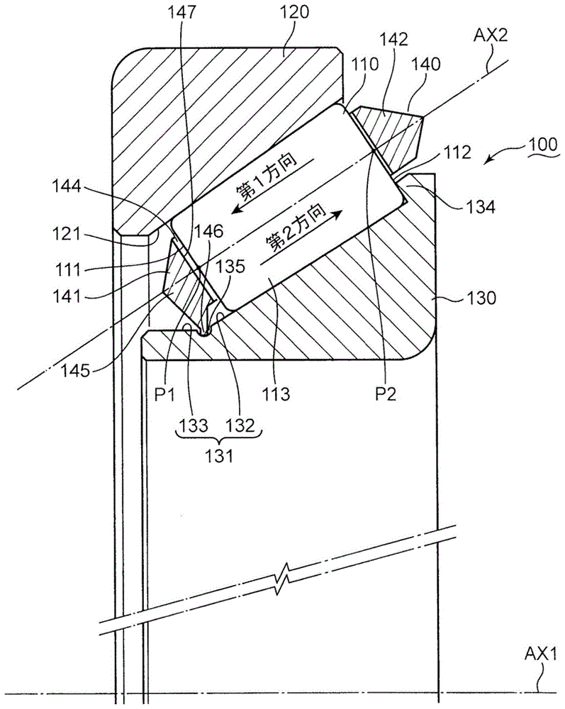
Fig. 1 is a schematic partial sectional view of a tapered roller bearing (roller bearing) 100 according to embodiment 1. The tapered roller bearing 100 is explained with reference to fig. 1.
The tapered roller bearing 100 includes a plurality of tapered rollers (rollers) 110 (fig. 1 shows 1 of the plurality of tapered rollers 110), an outer ring 120, an inner ring 130, and a cage 140. The outer race 120 and the inner race 130 are both annular. The roller 110 exemplifies a tapered roller. The roller 110 may also be a cylindrical roller. The inner race 130 is surrounded by the outer race 120. The outer race 120 and the inner race 130 cooperate to define an axis of rotation AX 1. The outer race 120 and the inner race 130 relatively rotate about the rotation axis AX 1.
The plurality of tapered rollers 110 are arranged in a ring shape between the outer ring 120 and the inner ring 130. The plurality of tapered rollers 110 are respectively rotated about a rotation axis AX2 that is inclined at a predetermined inclination angle (>0 °) with respect to the rotation axis AX 1. In the present embodiment, the roller axis is exemplified by the rotation axis AX 2.
Each of the plurality of tapered rollers 110 has a circular truncated cone shape (a cylindrical shape in the case of a cylindrical roller). Each of the plurality of tapered rollers 110 includes a 1 st end surface 111 having a substantially circular shape, a 2 nd end surface 112 having a substantially circular shape, and a circumferential surface 113 formed between the 1 st end surface 111 and the 2 nd end surface 112. The rotation axis AX2 passes through the center P1 of the 1 st end surface 111 and the center P2 of the 2 nd end surface 112. The 2 nd end surface 112 is larger than the 1 st end surface 111. The center P2 of the 2 nd end surface 112 is farther from the rotation axis AX1 than the center P1 of the 1 st end surface 111. That is, the tapered roller 110 has a 1 st end surface and a 2 nd end surface located on the outer side in the circumferential direction than the 1 st end surface.
The outer race 120 includes a rolling surface 121 inclined with respect to the rotation axis AX 1. The circumferential surface 113 of the tapered roller 110 abuts against the rolling surface 121. The tapered roller 110 rotates about the rotation axis AX2, and rolls on the rolling surface 121. In the present embodiment, the outer scroll surface is exemplified by scroll surface 121.
The inner race 130 includes an opposing surface 131 opposing the rolling surface 121 of the outer race 120. The opposite face 131 includes a rolling face 132 and an elongated face 133. The circumferential surface 113 of the tapered roller 110 also abuts against the rolling surface 132. The tapered roller 110 rotates about the rotation axis AX2, and rolls on the rolling surface 132. An elongated surface 133 extends from the rolling surface 132. The extension surface 133 is located closer to the 1 st end surface 111 than the 2 nd end surface 112 of the tapered roller 110. Unlike the rolling surface 132, which is inclined with respect to the rotation axis AX1, the elongated surface 133 is substantially parallel to the rotation axis AX 1. In the present embodiment, the inner rolling surface is exemplified by rolling surface 132.
The inner race 130 further includes a flange portion 134 that protrudes from the rolling surface 132 toward the outer race 120. The flange portion 134 abuts the 2 nd end surface 112 of the tapered roller 110.
Fig. 1 shows two arrows parallel to the rotation axis AX 2. In the following description, a direction indicated by an arrow indicating a direction from the 2 nd end surface 112 toward the 1 st end surface 111 is referred to as "1 st direction". In the following description, a direction indicated by an arrow indicating a direction from the 1 st end surface 111 toward the 2 nd end surface 112 is referred to as a "2 nd direction". The flange portion 134 restricts displacement of the tapered roller 110 in the 2 nd direction.
Fig. 2 is a schematic plan view of the holder 140. The tapered roller bearing 100 is further explained with reference to fig. 1 and 2.
As shown in fig. 1, the cage 140 is disposed between the outer ring 120 and the inner ring 130. The retainer 140 is used to restrict the displacement of the tapered rollers 110 in the 1 st direction and the 2 nd direction.
As shown in fig. 2, the holder 140 includes a 1 st restriction ring 141, a 2 nd restriction ring 142, and a plurality of coupling pieces 143. The 1 st restricting ring 141 is an annular portion adjacent to the 1 st end surface 111 of the tapered roller 110. The 2 nd restricting ring 142 is an annular portion adjacent to the 2 nd end surface 112 of the tapered roller 110. The 2 nd restriction ring 142 has a diameter larger than that of the 1 st restriction ring 141. The plurality of coupling pieces 143 are arranged at substantially equal intervals around the rotation axis AX1, and couple the 1 st restriction ring 141 and the 2 nd restriction ring 142. Thus, the holder 140 is circular truncated cone-shaped as a whole.
Substantially trapezoidal groove portions 144 are formed between the adjacent coupling pieces 143. The plurality of tapered rollers 110 are respectively accommodated in the plurality of groove portions 144 formed in the retainer 140.
As shown in fig. 1, the 1 st restriction ring 141 includes a main ring 145 and a protruding ring 146. The main ring 145 is an annular portion including a restricting surface 147 facing the 1 st end surface 111 of each of the plurality of tapered rollers 110. The projecting ring 146 is an annular portion projecting from the inner periphery of the main ring 145 toward the rotation axis AX 1. The restricting surface 147 abuts on the 1 st end surface 111 to restrict the displacement of the tapered roller 110 in the 1 st direction. In the present embodiment, the regulation loop is exemplified by the 1 st regulation loop 141.
A groove ring 135 is recessed in the opposing surface 131. The groove ring 135 is wound around the rotation axis AX1 over the entire circumference. The grommets 135 have a generally semi-circular cross-section. A groove ring 135 is formed along the boundary between the rolling surface 132 and the extension surface 133. The groove ring 135 is easily formed by the relief processing (japanese: ぬすみ加工) performed when the inner ring 130 is formed. The bead 146 of the 1 st restriction ring 141 engages with the groove ring 135. The retainer 140 is firmly fixed to the opposing surface 131 by the engagement between the bead 146 and the groove ring 135, and therefore the tapered roller 110 does not fall off. In this embodiment, the recess is exemplified by a bezel 135. The protrusion is exemplified by a bead 146.
< embodiment 2 >
The recess for engaging with the retainer may be formed in the extension surface. In this case, the overlapping length between the 1 st restriction turn and the rolling surface becomes short. As a result, the long tapered roller can be incorporated into the tapered roller bearing. In embodiment 2, an exemplary tapered roller bearing having a concave portion formed in an extended surface will be described.
Fig. 3 is a schematic partial sectional view of a tapered roller bearing 100A according to embodiment 2. The tapered roller bearing 100A is explained with reference to fig. 3. The description of embodiment 1 refers to elements denoted by the same reference numerals as those of embodiment 1.
As in embodiment 1, the tapered roller bearing 100A includes a plurality of tapered rollers 110 (fig. 3 shows 1 of the plurality of tapered rollers 110) and an outer ring 120. The description of embodiment 1 refers to these elements.
The tapered roller bearing 100A further includes an inner ring 130A and a cage 140A. As in embodiment 1, the inner race 130A includes a rolling surface 132 and a flange portion 134. The description of embodiment 1 refers to these elements.
Inner race 130A also includes an elongated surface 133A. An elongated surface 133A extends from the rolling surface 132. The extended surface 133A is located closer to the 1 st end surface 111 than the 2 nd end surface 112 of the tapered roller 110. Unlike the rolling surface 132 inclined with respect to the rotation axis AX1, the elongated surface 133A is substantially parallel to the rotation axis AX 1.
As in embodiment 1, the retainer 140A includes a 2 nd restricting ring 142 and a plurality of coupling pieces 143 (fig. 3 shows 1 of the plurality of coupling pieces 143). The description of embodiment 1 refers to these elements.
The holder 140A further includes a 1 st restriction ring 141A. The 1 st restricting ring 141A is an annular portion adjacent to the 1 st end surface 111 of the tapered roller 110. The 1 st restriction ring 141A includes a main ring 145, as in embodiment 1. The description of embodiment 1 is referred to the main ring 145.
The retainer 140A includes at least 3 protrusions 146A (fig. 3 shows 1 of the at least 3 protrusions 146A). The protrusion 146A is a nubby portion protruding from the inner periphery of the main ring 145 toward the rotation axis AX 1.
Unlike embodiment 1, the recess 135A, with which the protrusion 146A of the holder 140 engages, is recessed in the extended surface 133A. The recess 135A is formed corresponding to the protrusion 146A. The recess 135A has a substantially rectangular longitudinal section. The protrusion 146A has a rectangular shape in cross section complementary to the recess 135A. Thus, the protrusion 146A is firmly fitted into the recess 135A.
< embodiment 3 >
The recess portion that engages with the retainer may be formed on the rolling surface. In this case, the inner ring may not have an extension surface. As a result, the tapered roller bearing is reduced in weight. In embodiment 3, an exemplary tapered roller bearing having a concave portion formed on a rolling surface will be described.
Fig. 4 is a schematic partial sectional view of a tapered roller bearing 100B according to embodiment 3. The tapered roller bearing 100B is explained with reference to fig. 4. The description of embodiment 2 refers to elements denoted by the same reference numerals as embodiment 2.
As in embodiment 2, the tapered roller bearing 100B includes a plurality of tapered rollers 110 (fig. 4 shows 1 of the plurality of tapered rollers 110), an outer ring 120, and a retainer 140. The description of embodiment 2 refers to these elements.
The tapered roller bearing 100B further includes an inner ring 130B. As in embodiment 2, the inner race 130B includes a flange portion 134. The description of embodiment 2 is referred to the flange portion 134.
Inner race 130B also includes rolling surface 132B. The circumferential surface 113 of the tapered roller 110 abuts against the rolling surface 132B. The tapered roller 110 rotates about the rotation axis AX2, and rolls on the rolling surface 132B. Flange portion 134 protrudes from rolling surface 132B toward outer ring 120. In the present embodiment, the inner rolling surface is exemplified by rolling surface 132B.
Rolling surface 132B includes a base end edge 136 and a tip end edge 137 on the side opposite base end edge 136. The rolling surface 132B is inclined with respect to the rotation axis AX1 in a section from the base end edge 136 to the tip end edge 137.
Inner race 130B includes a top end face 138. The tip surface 138 forms an annular band region on an imaginary plane (not shown) that is perpendicular to the rotation axis AX1 and is defined so as to include the tip edge 137.
Unlike embodiment 2, a recess 135B, with which the protrusion 146A of the holder 140 engages, is recessed in a portion of the rolling surface 132B located near the distal end edge 137. The recess 135B is formed corresponding to the protrusion 146A. The recess 135B has a substantially rectangular longitudinal section. The protrusion 146A has a rectangular shape in cross section complementary to the recess 135B. Thus, the protrusion 146A is firmly fitted into the recess 135B.
The projection 146A is substantially perpendicular to the extending direction of the rotation axis AX1 with respect to the projecting direction of the main ring 145. Similarly, the recessed direction of the recessed portion 135B with respect to the rolling surface 132B is also substantially perpendicular to the extending direction of the rotation axis AX 1. Thus, the protrusion 146A is properly fitted into the recess 135B.
< embodiment 4 >
The concave direction of the concave portion recessed in the rolling surface may be perpendicular to the rotation axis of the tapered roller. In this case, the projection direction of the projection engaging with the recess is also set to be perpendicular to the rotation axis of the tapered roller. In embodiment 4, an exemplary tapered roller bearing having an engaging structure that is recessed and projected in a direction perpendicular to the rotation axis of the tapered roller will be described.
Fig. 5 is a schematic partial sectional view of a tapered roller bearing 100C according to embodiment 4. The tapered roller bearing 100C is explained with reference to fig. 5. The description of embodiment 3 refers to elements denoted by the same reference numerals as those of embodiment 3.
As in embodiment 3, the tapered roller bearing 100C includes a plurality of tapered rollers 110 (fig. 5 shows 1 of the plurality of tapered rollers 110) and an outer ring 120. The description of embodiment 3 refers to these elements.
The tapered roller bearing 100C further includes an inner ring 130C and a cage 140C. As in embodiment 3, the inner race 130C includes a flange portion 134 and a tip end surface 138. The description of embodiment 3 refers to these elements. As in embodiment 3, the retainer 140C includes a 2 nd restricting ring 142 and a plurality of coupling pieces 143 (fig. 5 shows 1 of the plurality of coupling pieces 143). The description of embodiment 3 refers to these elements.
Inner race 130C also includes rolling surface 132C. As in embodiment 3, rolling surface 132C includes a base edge 136 and a tip edge 137. The description of embodiment 3 refers to these elements.
The rolling surface 132C is inclined with respect to the rotation axis AX1 in a range from the base end edge 136 to the tip end edge 137. The circumferential surface 113 of the tapered roller 110 abuts against the rolling surface 132C. The tapered roller 110 rotates about the rotation axis AX2, and rolls on the rolling surface 132C. Flange 134 protrudes from rolling surface 132C toward outer ring 120. In the present embodiment, the inner rolling surface is exemplified by rolling surface 132C.
The recess 135C is recessed in a portion of the rolling surface 132C in the vicinity of the tip edge 137. The recess 135C has a substantially rectangular cross section. The recessed direction of the recess 135C with respect to the rolling surface 132C is substantially perpendicular to the extending direction of the rotation axis AX 2.
The holder 140C includes a 1 st restriction ring 141C. The 1 st restriction ring 141C includes a main ring 145, as in embodiment 3. The description of embodiment 3 is referred to the main ring 145.
The 1 st confinement ring 141C further includes at least 3 protrusions 146C (fig. 5 shows 1 of the at least 3 protrusions 146C). The protrusion 146C protrudes from the inner periphery of the main ring 145 in a direction at right angles to the rotation axis AX 2. The recess 135C is formed corresponding to the protrusion 146C. Thus, the protrusion 146C is properly fitted into the recess 135C. Further, the protrusion 146C has a rectangular-shaped longitudinal section complementary to the recess 135C. Thus, the protrusion 146C is firmly fitted into the recess 135C.
The design principle explained in association with the various embodiments described above can be applied to various tapered roller bearings. Some of the various features described in connection with one of the various embodiments described above may also be applied to a tapered roller bearing described in connection with another embodiment.
In the above embodiment, the cage is attached to the inner race. However, the same mounting configuration may also be applied to the outer race. The retainer 140 restricts displacement of the tapered roller 110 in the 1 st direction and the 2 nd direction only during assembly, and the 1 st restricting ring 141 and the 2 nd restricting ring 142 may be brought into a non-contact state after assembly. Similarly, after assembly, the recess and the projection may be in a non-contact state. Further, the assembling work can be performed in a state where the roller is directly hooked on the inner ring or the outer ring by the engagement of the protrusion and the recess and the retainer. The bottom surface of the concave portion shown in fig. 1 may be formed to have an arc-shaped cross section, or the convex portion may be formed to have a shape conforming to the arc-shaped cross section.
The roller bearing described in connection with the above-described embodiment mainly has the following features.
A roller bearing according to one aspect of the above embodiment has rollers that rotate about roller axes that are inclined with respect to the rotation axis. The roller bearing is provided with: an outer ring having an outer rolling surface on which the rollers roll; an inner ring surrounded by the outer ring and defining the axis of rotation; a retainer disposed between the outer ring and the inner ring so as to restrict displacement of the roller in an extending direction of the roller axis when assembled. The roller includes a 1 st end surface and a 2 nd end surface located on the outer side in the circumferential direction than the 1 st end surface. The retainer includes a restricting ring that can abut the 1 st end surface when assembled and restrict the displacement of the roller. The retainer is coupled to a portion of at least one of the inner ring and the outer ring on the 1 st end surface side.
According to the above configuration, since the retainer ring of the retainer abuts on the 1 st end surface, the retainer can properly restrict the displacement of the roller. Since the flange portion on the 1 st end surface side of the general roller bearing is not required, the roller can have a large dimension in the extending direction of the roller axis. Since the cage abutting on the 1 st end surface and restricting the displacement of the roller is coupled to at least one of the inner ring and the outer ring, the cage is appropriately fixed in the space surrounded by the outer ring and/or the inner ring without increasing the axial length dimension of the outer ring and/or the inner ring. Therefore, the long rollers can be incorporated into the roller bearing without increasing the axial length dimension of the roller bearing itself.
With the above configuration, the inner race may include an opposing surface opposing the outer rolling surface. The retainer may include a projection that engages with a recess recessed in the opposing surface.
According to the above configuration, the cage includes the protrusion that engages with the recess formed in the facing surface of the inner race that faces the outer rolling surface, and therefore the cage is appropriately held on the facing surface. Since the engagement structure formed by the recess and the projection is constructed in the space surrounded by the outer ring and/or the inner ring, the long roller is incorporated into the roller bearing without increasing the axial length of the roller bearing itself. Even if the recess is formed, the end portion of the inner ring on the 1 st end surface side is located on the 2 nd end surface side in the axial direction with respect to the end portion of the outer ring on the 1 st end surface side. Even if the recess is formed, the end portion of the inner ring on the 1 st end surface side does not fly out, and the axial length dimension of the roller bearing itself does not become long.
In the above configuration, the recess may be a groove ring formed on the opposing surface so as to surround the rotation axis. The protrusion may be a protruding ring that engages with the groove ring.
According to the above configuration, the protrusion is a protruding ring that engages with a groove ring formed on the opposing surface around the rotation axis, and therefore, the retainer is firmly fixed to the opposing surface. Therefore, the retainer can appropriately restrict the displacement of the roller to the small diameter side.
In the above configuration, the opposing surface may include an inner rolling surface on which the roller rolls and an elongated surface extending from the inner rolling surface in the extending direction of the rotation axis. The grove ring may be formed along a boundary between the inner rolling surface and the extension surface.
According to the above configuration, since the grooved ring is formed along the boundary between the inner rolling surface and the extended surface, a manufacturer who manufactures the inner ring can form the grooved ring by performing the relief processing. Thus, the roller bearing is formed without additional and/or special machining for forming the race.
In the above configuration, the opposing surface may include an inner rolling surface on which the roller rolls and an elongated surface extending from the inner rolling surface in the extending direction of the rotation axis. The recess may be formed in the extension surface.
According to the above configuration, since the recess is formed in the extension surface, the retainer can be easily attached to the inner ring.
In the above configuration, the opposing surface may be an inner rolling surface on which the roller rolls. The concave portion may be formed on the inner rolling surface.
According to the above configuration, since the concave portion is formed on the inner rolling surface, the above-described extension surface is not required. Thus, the roller bearing is lightened.
In the above configuration, the restricting ring may include a main ring including a restricting surface facing the 1 st end surface. The protrusion may be a protrusion protruding from the main ring in a direction perpendicular to the roller axis.
According to the above configuration, the protrusion protrudes from the main ring in the direction at right angles to the roller axis, and therefore, the retainer can have a simple shape around the protruding ring.
In the above configuration, the restricting ring may include a main ring including a restricting surface facing the 1 st end surface. The protrusion may be a protrusion protruding from the main ring in a direction perpendicular to the rotation axis.
According to the above configuration, since the projection projects from the main ring in the direction perpendicular to the rotation axis inclined with respect to the roller axis, a component force of a force acting in the extending direction of the roller axis acts in a direction of reinforcing the engagement between the bead ring and the groove ring. Thus, the projection is hard to fall off the bezel.
Industrial applicability
The principles of the above-described embodiments can be suitably applied to various technical fields using tapered roller bearings.