EP2000694B1 - Insert and retainer for securing same to an aircraft brake disk - Google Patents
Insert and retainer for securing same to an aircraft brake disk Download PDFInfo
- Publication number
- EP2000694B1 EP2000694B1 EP08157375A EP08157375A EP2000694B1 EP 2000694 B1 EP2000694 B1 EP 2000694B1 EP 08157375 A EP08157375 A EP 08157375A EP 08157375 A EP08157375 A EP 08157375A EP 2000694 B1 EP2000694 B1 EP 2000694B1
- Authority
- EP
- European Patent Office
- Prior art keywords
- insert
- notch
- retainer
- walls
- rotor
- Prior art date
- Legal status (The legal status is an assumption and is not a legal conclusion. Google has not performed a legal analysis and makes no representation as to the accuracy of the status listed.)
- Expired - Fee Related
Links
Images


Classifications
-
- F—MECHANICAL ENGINEERING; LIGHTING; HEATING; WEAPONS; BLASTING
- F16—ENGINEERING ELEMENTS AND UNITS; GENERAL MEASURES FOR PRODUCING AND MAINTAINING EFFECTIVE FUNCTIONING OF MACHINES OR INSTALLATIONS; THERMAL INSULATION IN GENERAL
- F16D—COUPLINGS FOR TRANSMITTING ROTATION; CLUTCHES; BRAKES
- F16D65/00—Parts or details
- F16D65/02—Braking members; Mounting thereof
- F16D65/12—Discs; Drums for disc brakes
- F16D65/125—Discs; Drums for disc brakes characterised by the material used for the disc body
- F16D65/126—Discs; Drums for disc brakes characterised by the material used for the disc body the material being of low mechanical strength, e.g. carbon, beryllium; Torque transmitting members therefor
-
- F—MECHANICAL ENGINEERING; LIGHTING; HEATING; WEAPONS; BLASTING
- F16—ENGINEERING ELEMENTS AND UNITS; GENERAL MEASURES FOR PRODUCING AND MAINTAINING EFFECTIVE FUNCTIONING OF MACHINES OR INSTALLATIONS; THERMAL INSULATION IN GENERAL
- F16D—COUPLINGS FOR TRANSMITTING ROTATION; CLUTCHES; BRAKES
- F16D55/00—Brakes with substantially-radial braking surfaces pressed together in axial direction, e.g. disc brakes
- F16D2055/0004—Parts or details of disc brakes
- F16D2055/0058—Fully lined, i.e. braking surface extending over the entire disc circumference
-
- F—MECHANICAL ENGINEERING; LIGHTING; HEATING; WEAPONS; BLASTING
- F16—ENGINEERING ELEMENTS AND UNITS; GENERAL MEASURES FOR PRODUCING AND MAINTAINING EFFECTIVE FUNCTIONING OF MACHINES OR INSTALLATIONS; THERMAL INSULATION IN GENERAL
- F16D—COUPLINGS FOR TRANSMITTING ROTATION; CLUTCHES; BRAKES
- F16D65/00—Parts or details
- F16D65/02—Braking members; Mounting thereof
- F16D2065/13—Parts or details of discs or drums
- F16D2065/134—Connection
- F16D2065/1356—Connection interlocking
- F16D2065/1364—Connection interlocking with relative movement axially
-
- F—MECHANICAL ENGINEERING; LIGHTING; HEATING; WEAPONS; BLASTING
- F16—ENGINEERING ELEMENTS AND UNITS; GENERAL MEASURES FOR PRODUCING AND MAINTAINING EFFECTIVE FUNCTIONING OF MACHINES OR INSTALLATIONS; THERMAL INSULATION IN GENERAL
- F16D—COUPLINGS FOR TRANSMITTING ROTATION; CLUTCHES; BRAKES
- F16D2200/00—Materials; Production methods therefor
- F16D2200/0034—Materials; Production methods therefor non-metallic
- F16D2200/0039—Ceramics
Definitions
- the present invention is directed toward an aircraft brake disk having one or more load distributing inserts and retainers for securing the inserts to the brake disk, and, more specifically, toward an aircraft brake disk having one or more load distributing inserts which inserts are radially retained by engagement with the brake disk and axially retained by a retainer which arrangement reduces or eliminates the need to rivet the retainer to the brake disk.
- Brake rotors and stators are sometimes formed from steel.
- carbon materials may comprise, for example, carbon embedded in a carbon fiber matrix, which material may be referred to generically as "carbon” or "carbon-carbon.”
- Carbon brake disks may also include notches in their outer peripheral walls for accommodating drive keys and in their inner peripheral walls for accommodating torque tube splines.
- these notches also typically include inserts to better distribute the load from the drive keys and/or splines to the rotor or stator and to reduce wear on the carbon brake disks. These inserts are typically formed from steel.
- EP-A-0 161 200 discloses a friction brake disk having a plurality of T-shape slots at a peripheral edge of the brake disk and each slot carries a metallic insert member.
- the insert member has the same T-shape and is configured to be inserted in the slot in the axial direction of the disk but restrained from being removed in the radial direction.
- a retaining clip is fastened to the insert member using fasteners for preventing movement in the axial direction by the insert member.
- GB-A-2 139 300 discloses a brake disk having an outer periphery with slots. Each slot receives a reinforcing insert. The inserts are U-shaped and are retained in their respective slots by clips secured to the disk adjacent to the slots.
- Inserts and retainers such as those described above perform in an acceptable manner.
- a typical rotor disk may have eight to twelve outer peripheral notches, and each retainer often requires about three rivets to secure. It is therefore necessary, in some cases, to drill about 36 openings, align those openings with openings in the retainers, and secure rivets in each of the openings. Similar difficulties are presented when installing inserts in stator inner peripheral walls. Such procedures add to the cost and complexity of rotor and stator assembly. It would therefore be desirable to reduce or eliminate the use of rivets when connecting inserts to rotor or stator disks.
- Figure 2 is a top plan view of the rotor insert of Figure 1 ;
- Figure 3 is a side elevational view of a retainer for holding an insert according to an embodiment of the present invention in a rotor;
- Figure 5 illustrates the retainer of Figure 3 being connected to the insert of Figure 1 after the insert of Figure 1 has been inserted into a notch in a rotor disk;
- Figure 6 is a side elevational view of the insert of Figure 1 mounted in a peripheral notch in a rotor disk and secured to the disk with the retainer of Figure 3 ;
- Figure 8 is a side elevational view of a rotor, insert and retainer according to another embodiment of the present invention.
- Figure 9 is a side elevational view of a rotor, insert and retainer according to another embodiment of the present invention.
- Figure 10 is a side elevational view of the insert of Figure 1 mounted in a peripheral notch of a stator
- Figure 11 illustrates a conventional rotor insert and retainer connected to a rotor disk by rivets.
- insert 10 can be axially inserted in notch 66; however, because the body 12 of insert 10 is wider than the portion of insert 10 at the ends 16 of legs 14, the insert cannot be radially inserted or removed.
- the engagement between insert 10 and notch 66 substantially prevents radially relative movement between the insert 10 and the rotor disk 60.
- Retainer 30 is then connected to insert 10 by moving central body portion 34 of the retainer into gap 18 in insert 10 until flaps 46 on the retainer 30 engage the spaced inner walls 20 near distal ends 16 of legs 14. As continued radial pressure is applied, flaps 46 flex toward second central portion side walls 44 to allow central portion 34 to enter gap 18 in insert 10. This process continues until the ends 50 of flaps 46 reach soffits 24 on inner walls 20 of insert legs 14 and are biased outwardly by the energy stored in hinge portions 48 when the flaps 46 were compressed. At this same time, parallel side walls 36 of retainer end portions 30 pass over rotor side walls 62 until top walls 38 of retainer end portions 32 contact peripheral wall portions 68 on either side of notch 66.
- a stator disk 110 is illustrated in Figure 10 and includes first and second side walls 112 (only one of which is illustrated) connected by an inner peripheral wall 114 having a notch 116.
- An insert 10 is mounted in notch 116 in inner peripheral wall 114 and secured in place with a retainer 118.
- Retainer 118 is generally similar to retainer 30 but is curved to fit the concave inner peripheral wall 114 of stator 110 rather than the convex outer peripheral wall 64 of rotor disk 60.
Description
- The present invention is directed toward an aircraft brake disk having one or more load distributing inserts and retainers for securing the inserts to the brake disk, and, more specifically, toward an aircraft brake disk having one or more load distributing inserts which inserts are radially retained by engagement with the brake disk and axially retained by a retainer which arrangement reduces or eliminates the need to rivet the retainer to the brake disk.
- BACKGROUND OF THE INVENTION
- A known type of aircraft brake system comprises a plurality of stator disks mounted to a fixed portion of a wheel support and a plurality of rotor disks connected for rotation with an aircraft wheel which rotors extend into spaces between the stators. When braking is required, a piston mounted next to this stack of disks is extended to compress the stack and force the rotors and stators into contact, thus slowing the rotors and the wheel attached thereto.
- Rotor drive keys are mounted on the interior of the aircraft wheel to engage the rotors and cause the rotors to rotate with the wheel. These drive keys are essentially metal bars that run parallel to the axis of the wheel and perpendicular to the major faces of the rotor disks. Each rotor disk includes a plurality of notches along its outer periphery through which the drive keys extend, and this notch-and-key arrangement circumferentially couples the rotors to the wheel. Similarly, splines are provided on the torque tube supporting the stators that engage notches on the inner peripheries of the stator disk to help fix the stators circumferentially relative to the torque tube.
- Brake rotors and stators are sometimes formed from steel. However, it is becoming common to form the rotor and stator disks from carbon materials. These materials may comprise, for example, carbon embedded in a carbon fiber matrix, which material may be referred to generically as "carbon" or "carbon-carbon." Carbon brake disks may also include notches in their outer peripheral walls for accommodating drive keys and in their inner peripheral walls for accommodating torque tube splines. However, because carbon can be more fragile than steel, these notches also typically include inserts to better distribute the load from the drive keys and/or splines to the rotor or stator and to reduce wear on the carbon brake disks. These inserts are typically formed from steel.
- A conventional rotor and rotor insert are illustrated in
Figure 10 which shows arotor 200 having first andsecond sides 202, only one of which is visible inFigure 10 , and an outerperipheral wall 204 connecting the 5sides 202. Anotch 206 extends intoperipheral wall 204 for receiving a drive key (not shown). The notch has abottom wall 208 and first andsecond side walls 210 extending away frombottom wall 208. Arotor insert 212 is mounted innotch 206 and includes abottom 214 overlyingnotch bottom wall 208 and first andsecond legs 216 extending frominsert bottom 214 along notch first andsecond side walls 210. Aretainer 218 overliesperipheral wall 204 and projects over the ends and sides ofinsert legs 216 to secureinsert 212 against axial and radial movement with respect to the rotor disk.Rivets 220 pass through openings (not shown) formed inrotor 200 to secure theretainer 218 to bothsides 202 of therotor 200. In use, a drive key (not shown) running throughnotch 206 will contactinsert legs 216 which in turn distribute the load from the drive key over theside walls 210 of thenotch 206. Similar inserts may be provided in an inner peripheral wall of a stator disk and secured to the stator disk in a similar manner. -
EP-A-0 161 200 discloses a friction brake disk having a plurality of T-shape slots at a peripheral edge of the brake disk and each slot carries a metallic insert member. The insert member has the same T-shape and is configured to be inserted in the slot in the axial direction of the disk but restrained from being removed in the radial direction. A retaining clip is fastened to the insert member using fasteners for preventing movement in the axial direction by the insert member. -
GB-A-2 139 300 - Inserts and retainers such as those described above perform in an acceptable manner. However, a typical rotor disk may have eight to twelve outer peripheral notches, and each retainer often requires about three rivets to secure. It is therefore necessary, in some cases, to drill about 36 openings, align those openings with openings in the retainers, and secure rivets in each of the openings. Similar difficulties are presented when installing inserts in stator inner peripheral walls. Such procedures add to the cost and complexity of rotor and stator assembly. It would therefore be desirable to reduce or eliminate the use of rivets when connecting inserts to rotor or stator disks.
- The present invention in its various aspects is as set out in the appended claims.
- BRIEF DESCRIPTION OF THE DRAWINGS
- These aspects and features of the invention and others will be better understood after a reading of the following detailed description together with the attached drawings wherein:
-
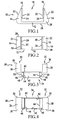
Figure 1 is a side elevational view of a rotor insert according to an embodiment of the present invention; -
Figure 2 is a top plan view of the rotor insert ofFigure 1 ; -
Figure 3 is a side elevational view of a retainer for holding an insert according to an embodiment of the present invention in a rotor; -
Figure 4 is a top plan view of the retainer ofFigure 3 ; -
Figure 5 illustrates the retainer ofFigure 3 being connected to the insert ofFigure 1 after the insert ofFigure 1 has been inserted into a notch in a rotor disk; -
Figure 6 is a side elevational view of the insert ofFigure 1 mounted in a peripheral notch in a rotor disk and secured to the disk with the retainer ofFigure 3 ; -
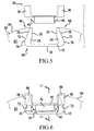
Figure 7 is a perspective view of a portion of the rotor disk ofFigure 5 taken in the direction of line VI-VI; -
Figure 8 is a side elevational view of a rotor, insert and retainer according to another embodiment of the present invention; -
Figure 9 is a side elevational view of a rotor, insert and retainer according to another embodiment of the present invention; -
Figure 10 is a side elevational view of the insert ofFigure 1 mounted in a peripheral notch of a stator; and -
Figure 11 illustrates a conventional rotor insert and retainer connected to a rotor disk by rivets. - DETAILED DESCRIPTION
- Referring now to the drawings, wherein the showings are for purposes of illustrating embodiments of the invention only and not for the purpose of limiting same,
Figures 1 and 2 illustrate aninsert 10 comprising abody 12 and first andsecond legs 14, each havingdistal ends 16, extending away frombody 12 and defining agap 18 therebetween.Legs 14 each have aninner wall 20 and anouter wall 22, and each of theinner walls 20 includes an underhang orsoffit 24. The distance betweeninner walls 20 neardistal ends 16 oflegs 14 is less than the distance between theinner walls 20 nearbody 12 of theinsert 10. Insert 10 further includes abottom 26 and first andsecond sides 28. It should be noted that relative terms such as "top" and "bottom" may occasionally be used herein for convenience. These terms refer to the orientation of various elements illustrated in the accompanying drawings. These descriptions are not intended to be limiting, and the positions of the various elements of the present invention will change when the invention is used. Furthermore, terms such as "radial" and "axial" are used with reference to thecircular rotor disk 60, part of the periphery of which is illustrated inFigures 5-9 . -
Figures 3 and 4 illustrate aretainer 30 comprising first andsecond end portions 32 connected by acentral portion 34.End portions 32 each include first and secondparallel side walls 36 and atop wall 38 connecting the first andsecond side walls 36.Central portion 34 is defined, in part, byflanges 40 comprises extensions of first andsecond side walls 36 twisted 90 degrees so that they are perpendicular to the first andsecond side walls 36. Fromflanges 40 depend a first pair ofcentral body walls 42 whichwalls 42 are connected by a second pair ofcentral body walls 44, forming a somewhat box-like structure between the first andsecond end portions 30. Each wall of the second pair ofcentral body walls 44 includes aflexible flap 46 connected to the second pair ofwalls 44 at ahinge portion 48 and having aterminal edge 50.Openings 52, best illustrated inFigure 7 , are defined by the central body second pair ofwalls 44 and the edges ofparallel side walls 36 andtop walls 38. - A
rotor disk 60 is illustrated inFigure 5 and includes first andsecond side walls 62 connected by an outerperipheral wall 64 having anotch 66 and first andsecond wall portions 68 on theperipheral wall 64 on either side ofnotch 66.Notch 66 has a bottom 70 and first andsecond sides 72 extending away from bottom 70 toward outerperipheral wall 64. According to an aspect of the present invention, first andsecond sides 72 ofnotch 66 can be linear or curved or have a shape formed of various lines and curves. In addition, a spacing between notch first andsecond sides 72 at a first point, such aspoint 76 inFigure 5 , is greater than a spacing between notch first andsecond sides 72 at a point radially outward ofpoint 76 such aspoint 78. This shape helps retain an insert, such asinsert 10, radially innotch 66 as described hereafter. It will be appreciated fromFigure 2 , for example, that the distal portions ofinsert 10 are narrower in the rotor thickness direction thanbody 12 ofinsert 10 to accommodateflanges 40 and to make the thickness ofretainer 30 atflanges 40 no greater than the thickness ofrotor disk 60. - The assembly of
insert 10,rotor disk 60 andretainer 30 will be described in connection withFigure 5 which showsinsert 10 already innotch 66 andretainer 30 being moved toward theinsert 10. As will be appreciated from the shapes ofinsert 10 and notch 66 illustrated inFigure 5 , insert 10 can be axially inserted innotch 66; however, because thebody 12 ofinsert 10 is wider than the portion ofinsert 10 at theends 16 oflegs 14, the insert cannot be radially inserted or removed. Thus the engagement betweeninsert 10 and notch 66 substantially prevents radially relative movement between theinsert 10 and therotor disk 60.Retainer 30 is then connected to insert 10 by movingcentral body portion 34 of the retainer intogap 18 ininsert 10 untilflaps 46 on theretainer 30 engage the spacedinner walls 20 near distal ends 16 oflegs 14. As continued radial pressure is applied, flaps 46 flex toward second centralportion side walls 44 to allowcentral portion 34 to entergap 18 ininsert 10. This process continues until the ends 50 offlaps 46reach soffits 24 oninner walls 20 ofinsert legs 14 and are biased outwardly by the energy stored inhinge portions 48 when theflaps 46 were compressed. At this same time,parallel side walls 36 ofretainer end portions 30 pass overrotor side walls 62 untiltop walls 38 ofretainer end portions 32 contactperipheral wall portions 68 on either side ofnotch 66. The engagement betweeninsert 10 and notch 66 substantially prevents theinsert 10 from being radially removed fromnotch 66, the engagement betweenflaps 46 andsoffits 24 substantially prevents theretainer 30 from being removed fromgap 18 ininsert 10, andretainer side walls 32, overlying portions of insert first andsecond sides 28, substantially preventinsert 10 from moving axially relative torotor 10. With this arrangement, insert 10 is securely retained inrotor disk 60 without the use of rivets. - A
stator disk 110 is illustrated inFigure 10 and includes first and second side walls 112 (only one of which is illustrated) connected by an innerperipheral wall 114 having anotch 116. Aninsert 10 is mounted innotch 116 in innerperipheral wall 114 and secured in place with aretainer 118.Retainer 118 is generally similar toretainer 30 but is curved to fit the concave innerperipheral wall 114 ofstator 110 rather than the convex outerperipheral wall 64 ofrotor disk 60. - A second embodiment of the present invention is illustrated in
Figure 8 and includesrotor disk 60 and insert 10 of the previous embodiment. In this embodiment, adifferent retainer 80 is provided for axially retaininginsert 10 inrotor disk 60.Retainer 80 includes first andsecond end portions 82 and acentral portion 84 between theend portions 82. Theend portions 82 include first and secondparallel side walls 86 overlying theside walls 62 ofrotor 60 and atop wall 88 overlying theperipheral wall portions 68 ofrotor 60.Central portion 84 includes acentral wall 90 generally parallel to the bottom 70 ofnotch 66, and afastener 92, such as a screw or a bolt is threadedly secured to anopening 94 inbody 12 ofinsert 10. In this manner, one connector is used to connect theretainer 80 to theinsert 10, but no connections directly to the rotor disk are required. A similar arrangement may be used to secure aninsert 10 to anotch 116 in the innerperipheral wall 118 ofstator 110. - A third embodiment of the present invention is disclosed in
Figure 9 and uses thesame rotor 60 and insert 10 of the previous embodiments and an alternate retainer 100. Retainer 100 comprises a pair ofbars 102, only one of which is visible inFigure 9 , connected toopposite sides 62 ofrotor 60 acrossnotch 66 withrivets 104.Bars 102retain insert 10 axially innotch 66 while the complementary shapes ofinsert 10 and notch 66 radially retain theinsert 10. While this embodiment uses rivets to connect the retainer 100 to therotor disk 60, it may allow for a reduction in the number of rivets needed as compared with certain prior arrangements. A similar arrangement may be used to secure aninsert 10 to anotch 116 in the innerperipheral wall 118 ofstator 110. - The present invention has been described herein in terms of several embodiments. Obvious modifications and additions to these embodiments will become apparent to those skilled in the relevant art upon a reading of the foregoing disclosure. It is intended that all such modifications and additions comprise a part of the present invention to the extent they fall within the scope of the several claims appended hereto.
Claims (9)
- An aircraft brake element comprising:a circular rotor or stator disk (60, 110) having first and second walls (62, 112) and a peripheral wall (64, 114) connecting said first and second walls (62, 112), said peripheral wall (64, 114) including at least one notch (66, 116) having a bottom (70) and first and second sides (72) extending away from said bottom (70) and first and second edges at said peripheral wall (64, 114),an insert (10) mounted in said notch (66, 116) and having first and second legs (14) extending along said notch first and second sides (72), said first and second legs (14) including inner and outer walls (20, 22);said insert (10) and notch (66, 116) being mutually configured such that said insert (10) is axially but not radially removable from said notch (66, 116), anda retainer (30, 80, 100, 118) overlying said disk first and second walls (62, 112) to limit axial movement of said insert (10) relative to said rotor or stator disk (60, 110) characterised in that said retention means (36, 38, 44, 46) comprises a flexible flap (46) engaging a portion (24) of the insert first side inner wall (20).
- The aircraft brake element of claim 1 wherein
said insert (10) includes a first portion having a first width between said outer walls (22) of said insert first and second legs (14),
a circumferential distance between said notch first side and said notch second side (72) at a position between said notch edge and said insert first portion has a width less than said insert first portion first width. - The aircraft brake element of claim 1 wherein the distance between said notch first and second sides (72) at said notch bottom (70) is greater than the distance between said notch first and second sides (72) at said peripheral wall (64, 114).
- The aircraft brake element of claim 1 wherein said retainer (30, 80, 100, 118) includes retention means (36, 38, 44, 46) holding said retainer (30, 80, 100, 118) on said rotor or stator disk (60, 110).
- The aircraft brake element of claim 1 wherein each of said inner walls (20) includes a soffit (24).
- The aircraft brake element of claim 6 wherein said flexible retainer flap (46) engages said soffits (24) of said inner walls (20).
- The aircraft brake element of claim 1 wherein said retainer (30, 80, 100, 118) is connected to said insert (10).
- A method of securing an insert (10) in a peripheral notch (64, 114) of an aircraft brake element (60, 110) comprising the steps of:providing an aircraft brake disk (60, 110) having first and second sides (62, 112) and a peripheral wall (64, 114) having a notch (66, 116), the notch (66, 116) having side edges (72) converging in a direction toward the peripheral wall (64, 114) having the notch (66, 116);providing an insert (10) comprising a central body (12) and first and second legs (14) projecting from the central body (12), outer portions (22) of the first and second legs (14) converging toward each other;axially inserting the insert (10) into the peripheral notch (66, 116);providing a retainer (30, 80, 100, 118) having a central portion (34) and having first and second parallel walls (36), said retainer (30, 80, 100, 118) including first and second flexible flaps (46) engaging a portion (24) of each of the first and second legs (14);radially inserting the central portion (34) of the retainer (30, 80, 100, 118) into the notch (66, 116) such that the retainer first and second parallel walls (36) overlie the rotor first and second sides (62,112); andsecuring the retainer (30, 80, 100, 118) to the insert (10).
- The method of claim 8 wherein said step of providing a retainer having a central portion comprises the step of providing a retainer (30, 80, 100, 118) having a central portion (34) having said first and second flexible flaps (46) projecting away from the central portion (34) and from each other and wherein the step of radially inserting the central portion (34) into the notch (10) comprises the step of inserting the central portion (34) until the flaps (46) each engage a soffit (24) on the first and second legs (14).
Applications Claiming Priority (1)
| Application Number | Priority Date | Filing Date | Title |
|---|---|---|---|
| US11/806,771 US7766133B2 (en) | 2007-06-04 | 2007-06-04 | Insert and retainer for securing same to an aircraft brake disk |
Publications (2)
| Publication Number | Publication Date |
|---|---|
| EP2000694A1 EP2000694A1 (en) | 2008-12-10 |
| EP2000694B1 true EP2000694B1 (en) | 2009-12-09 |
Family
ID=39683587
Family Applications (1)
| Application Number | Title | Priority Date | Filing Date |
|---|---|---|---|
| EP08157375A Expired - Fee Related EP2000694B1 (en) | 2007-06-04 | 2008-05-30 | Insert and retainer for securing same to an aircraft brake disk |
Country Status (3)
| Country | Link |
|---|---|
| US (1) | US7766133B2 (en) |
| EP (1) | EP2000694B1 (en) |
| DE (1) | DE602008000373D1 (en) |
Families Citing this family (15)
| Publication number | Priority date | Publication date | Assignee | Title |
|---|---|---|---|---|
| US9976612B2 (en) * | 2015-11-11 | 2018-05-22 | Goodrich Corporation | Single fastener brake disk insert retainer |
| US9897153B2 (en) | 2015-11-11 | 2018-02-20 | Goodrich Corporation | Low radial profile brake disk insert retainer |
| FR3049668B1 (en) * | 2016-03-31 | 2019-06-14 | Airbus Operations (S.A.S.) | BRAKE DISC FOR AN AIRCRAFT |
| US10221905B2 (en) * | 2016-11-09 | 2019-03-05 | Goodrich Corporation | Bridged clip retainer for brake system |
| FR3065439B1 (en) * | 2017-04-24 | 2020-08-14 | Safran Landing Systems | PROCESS FOR MITIGATION OF VIBRATIONS OF BRAKED AIRCRAFT WHEELS |
| US10274034B2 (en) | 2017-07-12 | 2019-04-30 | Goodrich Corporation | Wear liner with integrated torque button |
| US10436265B2 (en) * | 2017-08-10 | 2019-10-08 | Goodrich Corporation | Rivet-less rotor clip design |
| US10941823B2 (en) | 2017-11-27 | 2021-03-09 | Goodrich Corporation | Segmented wear liner |
| DE102017129684B4 (en) * | 2017-12-13 | 2024-01-25 | Knorr-Bremse Systeme für Nutzfahrzeuge GmbH | Brake discs/hub connection |
| US10962069B2 (en) | 2019-03-20 | 2021-03-30 | Goodrich Corporation | Segmented rivetless wear liner with structural carbon or ceramic core |
| US11644070B2 (en) | 2020-01-22 | 2023-05-09 | Honeywell International Inc. | Brake disc insert with retainer |
| US11585387B2 (en) | 2020-02-24 | 2023-02-21 | Honeywell International Inc. | Rotor drive key assembly |
| US11346416B2 (en) * | 2020-04-23 | 2022-05-31 | Honeywell International Inc. | Brake disc insert with bridge member |
| US11560930B2 (en) | 2020-10-23 | 2023-01-24 | Honeywell International Inc. | Brake disc insert with retainer |
| EP4155570B1 (en) | 2021-09-24 | 2024-04-17 | Goodrich Corporation | Rotor clip for brake assembly |
Family Cites Families (24)
| Publication number | Priority date | Publication date | Assignee | Title |
|---|---|---|---|---|
| US3550740A (en) | 1968-05-03 | 1970-12-29 | Goodrich Co B F | Segmented friction member for brake or clutch |
| DE2017787A1 (en) | 1969-04-07 | 1971-01-07 | Goodrich Co B F | High-performance brake and brake lining for it |
| US3605967A (en) * | 1969-04-07 | 1971-09-20 | Goodrich Co B F | Protective bearing member for brake or clutch |
| US3670858A (en) | 1971-04-26 | 1972-06-20 | Russell F Van Horn | Segmental friction member for brake or clutch |
| US3907076A (en) | 1971-05-24 | 1975-09-23 | Goodyear Aerospace Corp | Key slot segments for driving brake discs |
| US3972395A (en) | 1974-03-29 | 1976-08-03 | The Bendix Corporation | Oxidation inhibiting caps for carbon friction disc |
| US4007814A (en) | 1976-02-05 | 1977-02-15 | Goodyear Aerospace Corporation | Carbon brake disk with cast keyslot reinforcement members |
| US4155432A (en) | 1977-08-24 | 1979-05-22 | Goodyear Aerospace Corporation | Rigid segmented brake disk |
| US4465165A (en) | 1983-01-28 | 1984-08-14 | The B. F. Goodrich Company | Brake apparatus |
| US4511021A (en) | 1983-04-21 | 1985-04-16 | The B. F. Goodrich Company | Brake apparatus |
| US4557356A (en) | 1984-04-30 | 1985-12-10 | Goodyear Aerospace Corporation | Brake disk and keyslot reinforcements therefor |
| GB8428953D0 (en) | 1984-11-16 | 1984-12-27 | Dunlop Ltd | Bonding of carbon-based components |
| US4747473A (en) | 1986-06-19 | 1988-05-31 | The B. F. Goodrich Company | Segmented friction brake or clutch disc assembly |
| US4784246A (en) * | 1987-02-18 | 1988-11-15 | The B. F. Goodrich Company | Brake apparatus |
| US4863001A (en) | 1987-02-18 | 1989-09-05 | The Bf Goodrich Company | Brake apparatus |
| FR2629888B1 (en) | 1988-04-08 | 1991-02-22 | Messier Hispano Sa | CARBON BRAKE ROTOR DISC EQUIPPED WITH REINFORCEMENT RIDERS |
| US5143184A (en) | 1991-02-14 | 1992-09-01 | Allied-Signal Inc. | Carbon composite brake disc with positive vibration damping |
| US5273140A (en) | 1992-09-25 | 1993-12-28 | Allied-Signal Inc. | Brake disc annular drive insert |
| FR2719879B1 (en) | 1994-05-11 | 1996-06-07 | Messier Bugatti | Reinforcement device for carbon brake discs, and brake disc equipped with such devices. |
| DE19544559C1 (en) | 1995-11-30 | 1997-07-03 | Knorr Bremse Systeme | Two-piece brake disc, especially for commercial vehicle disc brakes |
| ATE284981T1 (en) | 1999-03-12 | 2005-01-15 | Goodrich Corp | FERROUS METAL ARTICLE WITH A COATING OF AN OXIDE OF THE BASE METAL USABLE FOR BRAKE DEVICES ETC. |
| US6464045B2 (en) | 2001-03-15 | 2002-10-15 | Delphi Technologies, Inc. | Rotor retaining clip |
| DE102004062795A1 (en) | 2004-12-20 | 2006-06-29 | Spindelfabrik Süssen Schurr Stahlecker & Grill GmbH | Rotor plate, for an open-end spinner, is an insert with the fiber sliding surface and collection groove to be secured at the rotor base body by a clamping ring |
| US20070193836A1 (en) | 2006-02-23 | 2007-08-23 | Walker Terence B | Method and brake disc with composite insert member |
-
2007
- 2007-06-04 US US11/806,771 patent/US7766133B2/en not_active Expired - Fee Related
-
2008
- 2008-05-30 DE DE602008000373T patent/DE602008000373D1/en active Active
- 2008-05-30 EP EP08157375A patent/EP2000694B1/en not_active Expired - Fee Related
Also Published As
| Publication number | Publication date |
|---|---|
| EP2000694A1 (en) | 2008-12-10 |
| US7766133B2 (en) | 2010-08-03 |
| DE602008000373D1 (en) | 2010-01-21 |
| US20080296109A1 (en) | 2008-12-04 |
Similar Documents
| Publication | Publication Date | Title |
|---|---|---|
| EP2000694B1 (en) | Insert and retainer for securing same to an aircraft brake disk | |
| EP1988305B1 (en) | Load-distributing rotor insert for aircraft brakes | |
| US4478554A (en) | Fan blade axial and radial retention device | |
| US8096776B2 (en) | Turbine blade assembly | |
| US4863001A (en) | Brake apparatus | |
| US7871134B2 (en) | Wheel hub comprising axial recesses formed between the holes for lug bolts | |
| US5584659A (en) | Device for fixing turbine blades and for eliminating rotor balance errors in axially flow-through compressors or turbines of gas turbine drives | |
| US7708529B2 (en) | Rotor of a turbo engine, e.g., a gas turbine rotor | |
| JP4406259B2 (en) | Continuous radial biasing device and method for a reaction bucket of a steam turbine | |
| US4227594A (en) | Backing plate-wheel cylinder retaining clip | |
| CA2498144A1 (en) | Blade retention scheme using a retention tab | |
| US8360221B2 (en) | Segmented support plate for a lamella, and lamella having a segmented support plate of said type | |
| EP1507067B1 (en) | Inner air seal anti-rotation device | |
| US20080029363A1 (en) | Snap-ring with additional loop | |
| JP2009520168A (en) | Clutch attached to the outer edge of the torque converter and method for assembling the clutch into the torque converter | |
| US5267797A (en) | Combined radial/axial friction bearing and method for its manufacture | |
| US4784246A (en) | Brake apparatus | |
| EP1738091B1 (en) | Method and apparatus for protecting a friction brake disc | |
| GB2424314A (en) | Re-tightenable stator body slot wedge system | |
| US6827554B2 (en) | Axial entry turbine bucket dovetail with integral anti-rotation key | |
| EP0200815B1 (en) | Mounting shaft to pulley formed of sheet metal | |
| US4130399A (en) | Dismantling tool | |
| EP1961986B1 (en) | Aircraft brake system | |
| EP1616080B1 (en) | Stacked wheel assembly for the rotor of a rotary machine | |
| CN114483827A (en) | Brake disc lining with retainer |
Legal Events
| Date | Code | Title | Description |
|---|---|---|---|
| PUAI | Public reference made under article 153(3) epc to a published international application that has entered the european phase |
Free format text: ORIGINAL CODE: 0009012 |
|
| 17P | Request for examination filed |
Effective date: 20080530 |
|
| AK | Designated contracting states |
Kind code of ref document: A1 Designated state(s): AT BE BG CH CY CZ DE DK EE ES FI FR GB GR HR HU IE IS IT LI LT LU LV MC MT NL NO PL PT RO SE SI SK TR |
|
| AX | Request for extension of the european patent |
Extension state: AL BA MK RS |
|
| 17Q | First examination report despatched |
Effective date: 20090115 |
|
| GRAP | Despatch of communication of intention to grant a patent |
Free format text: ORIGINAL CODE: EPIDOSNIGR1 |
|
| AKX | Designation fees paid |
Designated state(s): DE FR GB |
|
| GRAS | Grant fee paid |
Free format text: ORIGINAL CODE: EPIDOSNIGR3 |
|
| GRAA | (expected) grant |
Free format text: ORIGINAL CODE: 0009210 |
|
| AK | Designated contracting states |
Kind code of ref document: B1 Designated state(s): DE FR GB |
|
| REG | Reference to a national code |
Ref country code: GB Ref legal event code: FG4D |
|
| REF | Corresponds to: |
Ref document number: 602008000373 Country of ref document: DE Date of ref document: 20100121 Kind code of ref document: P |
|
| PLBE | No opposition filed within time limit |
Free format text: ORIGINAL CODE: 0009261 |
|
| STAA | Information on the status of an ep patent application or granted ep patent |
Free format text: STATUS: NO OPPOSITION FILED WITHIN TIME LIMIT |
|
| 26N | No opposition filed |
Effective date: 20100910 |
|
| PGFP | Annual fee paid to national office [announced via postgrant information from national office to epo] |
Ref country code: DE Payment date: 20120531 Year of fee payment: 5 |
|
| PGFP | Annual fee paid to national office [announced via postgrant information from national office to epo] |
Ref country code: GB Payment date: 20120426 Year of fee payment: 5 Ref country code: FR Payment date: 20120510 Year of fee payment: 5 |
|
| GBPC | Gb: european patent ceased through non-payment of renewal fee |
Effective date: 20130530 |
|
| PG25 | Lapsed in a contracting state [announced via postgrant information from national office to epo] |
Ref country code: DE Free format text: LAPSE BECAUSE OF NON-PAYMENT OF DUE FEES Effective date: 20131203 |
|
| REG | Reference to a national code |
Ref country code: DE Ref legal event code: R119 Ref document number: 602008000373 Country of ref document: DE Effective date: 20131203 |
|
| REG | Reference to a national code |
Ref country code: FR Ref legal event code: ST Effective date: 20140131 |
|
| PG25 | Lapsed in a contracting state [announced via postgrant information from national office to epo] |
Ref country code: GB Free format text: LAPSE BECAUSE OF NON-PAYMENT OF DUE FEES Effective date: 20130530 |
|
| PG25 | Lapsed in a contracting state [announced via postgrant information from national office to epo] |
Ref country code: FR Free format text: LAPSE BECAUSE OF NON-PAYMENT OF DUE FEES Effective date: 20130531 |
|
| P01 | Opt-out of the competence of the unified patent court (upc) registered |
Effective date: 20230525 |