EP4394161A2 - Electric compressor with modular stator assembly - Google Patents
Electric compressor with modular stator assembly Download PDFInfo
- Publication number
- EP4394161A2 EP4394161A2 EP23214102.8A EP23214102A EP4394161A2 EP 4394161 A2 EP4394161 A2 EP 4394161A2 EP 23214102 A EP23214102 A EP 23214102A EP 4394161 A2 EP4394161 A2 EP 4394161A2
- Authority
- EP
- European Patent Office
- Prior art keywords
- motor
- housing
- refrigerant
- drive shaft
- electric compressor
- Prior art date
- Legal status (The legal status is an assumption and is not a legal conclusion. Google has not performed a legal analysis and makes no representation as to the accuracy of the status listed.)
- Pending
Links
Images
























Classifications
-
- F—MECHANICAL ENGINEERING; LIGHTING; HEATING; WEAPONS; BLASTING
- F04—POSITIVE - DISPLACEMENT MACHINES FOR LIQUIDS; PUMPS FOR LIQUIDS OR ELASTIC FLUIDS
- F04C—ROTARY-PISTON, OR OSCILLATING-PISTON, POSITIVE-DISPLACEMENT MACHINES FOR LIQUIDS; ROTARY-PISTON, OR OSCILLATING-PISTON, POSITIVE-DISPLACEMENT PUMPS
- F04C23/00—Combinations of two or more pumps, each being of rotary-piston or oscillating-piston type, specially adapted for elastic fluids; Pumping installations specially adapted for elastic fluids; Multi-stage pumps specially adapted for elastic fluids
- F04C23/008—Hermetic pumps
-
- F—MECHANICAL ENGINEERING; LIGHTING; HEATING; WEAPONS; BLASTING
- F01—MACHINES OR ENGINES IN GENERAL; ENGINE PLANTS IN GENERAL; STEAM ENGINES
- F01C—ROTARY-PISTON OR OSCILLATING-PISTON MACHINES OR ENGINES
- F01C21/00—Component parts, details or accessories not provided for in groups F01C1/00 - F01C20/00
- F01C21/10—Outer members for co-operation with rotary pistons; Casings
-
- F—MECHANICAL ENGINEERING; LIGHTING; HEATING; WEAPONS; BLASTING
- F04—POSITIVE - DISPLACEMENT MACHINES FOR LIQUIDS; PUMPS FOR LIQUIDS OR ELASTIC FLUIDS
- F04B—POSITIVE-DISPLACEMENT MACHINES FOR LIQUIDS; PUMPS
- F04B35/00—Piston pumps specially adapted for elastic fluids and characterised by the driving means to their working members, or by combination with, or adaptation to, specific driving engines or motors, not otherwise provided for
- F04B35/04—Piston pumps specially adapted for elastic fluids and characterised by the driving means to their working members, or by combination with, or adaptation to, specific driving engines or motors, not otherwise provided for the means being electric
-
- F—MECHANICAL ENGINEERING; LIGHTING; HEATING; WEAPONS; BLASTING
- F04—POSITIVE - DISPLACEMENT MACHINES FOR LIQUIDS; PUMPS FOR LIQUIDS OR ELASTIC FLUIDS
- F04C—ROTARY-PISTON, OR OSCILLATING-PISTON, POSITIVE-DISPLACEMENT MACHINES FOR LIQUIDS; ROTARY-PISTON, OR OSCILLATING-PISTON, POSITIVE-DISPLACEMENT PUMPS
- F04C18/00—Rotary-piston pumps specially adapted for elastic fluids
- F04C18/02—Rotary-piston pumps specially adapted for elastic fluids of arcuate-engagement type, i.e. with circular translatory movement of co-operating members, each member having the same number of teeth or tooth-equivalents
- F04C18/0207—Rotary-piston pumps specially adapted for elastic fluids of arcuate-engagement type, i.e. with circular translatory movement of co-operating members, each member having the same number of teeth or tooth-equivalents both members having co-operating elements in spiral form
- F04C18/0215—Rotary-piston pumps specially adapted for elastic fluids of arcuate-engagement type, i.e. with circular translatory movement of co-operating members, each member having the same number of teeth or tooth-equivalents both members having co-operating elements in spiral form where only one member is moving
-
- F—MECHANICAL ENGINEERING; LIGHTING; HEATING; WEAPONS; BLASTING
- F04—POSITIVE - DISPLACEMENT MACHINES FOR LIQUIDS; PUMPS FOR LIQUIDS OR ELASTIC FLUIDS
- F04C—ROTARY-PISTON, OR OSCILLATING-PISTON, POSITIVE-DISPLACEMENT MACHINES FOR LIQUIDS; ROTARY-PISTON, OR OSCILLATING-PISTON, POSITIVE-DISPLACEMENT PUMPS
- F04C18/00—Rotary-piston pumps specially adapted for elastic fluids
- F04C18/02—Rotary-piston pumps specially adapted for elastic fluids of arcuate-engagement type, i.e. with circular translatory movement of co-operating members, each member having the same number of teeth or tooth-equivalents
- F04C18/0207—Rotary-piston pumps specially adapted for elastic fluids of arcuate-engagement type, i.e. with circular translatory movement of co-operating members, each member having the same number of teeth or tooth-equivalents both members having co-operating elements in spiral form
- F04C18/0246—Details concerning the involute wraps or their base, e.g. geometry
- F04C18/0269—Details concerning the involute wraps
- F04C18/0284—Details of the wrap tips
-
- F—MECHANICAL ENGINEERING; LIGHTING; HEATING; WEAPONS; BLASTING
- F04—POSITIVE - DISPLACEMENT MACHINES FOR LIQUIDS; PUMPS FOR LIQUIDS OR ELASTIC FLUIDS
- F04C—ROTARY-PISTON, OR OSCILLATING-PISTON, POSITIVE-DISPLACEMENT MACHINES FOR LIQUIDS; ROTARY-PISTON, OR OSCILLATING-PISTON, POSITIVE-DISPLACEMENT PUMPS
- F04C23/00—Combinations of two or more pumps, each being of rotary-piston or oscillating-piston type, specially adapted for elastic fluids; Pumping installations specially adapted for elastic fluids; Multi-stage pumps specially adapted for elastic fluids
- F04C23/02—Pumps characterised by combination with, or adaptation to, specific driving engines or motors
-
- F—MECHANICAL ENGINEERING; LIGHTING; HEATING; WEAPONS; BLASTING
- F04—POSITIVE - DISPLACEMENT MACHINES FOR LIQUIDS; PUMPS FOR LIQUIDS OR ELASTIC FLUIDS
- F04C—ROTARY-PISTON, OR OSCILLATING-PISTON, POSITIVE-DISPLACEMENT MACHINES FOR LIQUIDS; ROTARY-PISTON, OR OSCILLATING-PISTON, POSITIVE-DISPLACEMENT PUMPS
- F04C27/00—Sealing arrangements in rotary-piston pumps specially adapted for elastic fluids
- F04C27/005—Axial sealings for working fluid
-
- F—MECHANICAL ENGINEERING; LIGHTING; HEATING; WEAPONS; BLASTING
- F04—POSITIVE - DISPLACEMENT MACHINES FOR LIQUIDS; PUMPS FOR LIQUIDS OR ELASTIC FLUIDS
- F04C—ROTARY-PISTON, OR OSCILLATING-PISTON, POSITIVE-DISPLACEMENT MACHINES FOR LIQUIDS; ROTARY-PISTON, OR OSCILLATING-PISTON, POSITIVE-DISPLACEMENT PUMPS
- F04C29/00—Component parts, details or accessories of pumps or pumping installations, not provided for in groups F04C18/00 - F04C28/00
- F04C29/0042—Driving elements, brakes, couplings, transmissions specially adapted for pumps
- F04C29/0085—Prime movers
-
- F—MECHANICAL ENGINEERING; LIGHTING; HEATING; WEAPONS; BLASTING
- F04—POSITIVE - DISPLACEMENT MACHINES FOR LIQUIDS; PUMPS FOR LIQUIDS OR ELASTIC FLUIDS
- F04C—ROTARY-PISTON, OR OSCILLATING-PISTON, POSITIVE-DISPLACEMENT MACHINES FOR LIQUIDS; ROTARY-PISTON, OR OSCILLATING-PISTON, POSITIVE-DISPLACEMENT PUMPS
- F04C29/00—Component parts, details or accessories of pumps or pumping installations, not provided for in groups F04C18/00 - F04C28/00
- F04C29/04—Heating; Cooling; Heat insulation
- F04C29/045—Heating; Cooling; Heat insulation of the electric motor in hermetic pumps
-
- F—MECHANICAL ENGINEERING; LIGHTING; HEATING; WEAPONS; BLASTING
- F04—POSITIVE - DISPLACEMENT MACHINES FOR LIQUIDS; PUMPS FOR LIQUIDS OR ELASTIC FLUIDS
- F04B—POSITIVE-DISPLACEMENT MACHINES FOR LIQUIDS; PUMPS
- F04B53/00—Component parts, details or accessories not provided for in, or of interest apart from, groups F04B1/00 - F04B23/00 or F04B39/00 - F04B47/00
- F04B53/22—Arrangements for enabling ready assembly or disassembly
-
- F—MECHANICAL ENGINEERING; LIGHTING; HEATING; WEAPONS; BLASTING
- F04—POSITIVE - DISPLACEMENT MACHINES FOR LIQUIDS; PUMPS FOR LIQUIDS OR ELASTIC FLUIDS
- F04C—ROTARY-PISTON, OR OSCILLATING-PISTON, POSITIVE-DISPLACEMENT MACHINES FOR LIQUIDS; ROTARY-PISTON, OR OSCILLATING-PISTON, POSITIVE-DISPLACEMENT PUMPS
- F04C18/00—Rotary-piston pumps specially adapted for elastic fluids
- F04C18/02—Rotary-piston pumps specially adapted for elastic fluids of arcuate-engagement type, i.e. with circular translatory movement of co-operating members, each member having the same number of teeth or tooth-equivalents
-
- F—MECHANICAL ENGINEERING; LIGHTING; HEATING; WEAPONS; BLASTING
- F04—POSITIVE - DISPLACEMENT MACHINES FOR LIQUIDS; PUMPS FOR LIQUIDS OR ELASTIC FLUIDS
- F04C—ROTARY-PISTON, OR OSCILLATING-PISTON, POSITIVE-DISPLACEMENT MACHINES FOR LIQUIDS; ROTARY-PISTON, OR OSCILLATING-PISTON, POSITIVE-DISPLACEMENT PUMPS
- F04C2240/00—Components
- F04C2240/30—Casings or housings
-
- F—MECHANICAL ENGINEERING; LIGHTING; HEATING; WEAPONS; BLASTING
- F04—POSITIVE - DISPLACEMENT MACHINES FOR LIQUIDS; PUMPS FOR LIQUIDS OR ELASTIC FLUIDS
- F04C—ROTARY-PISTON, OR OSCILLATING-PISTON, POSITIVE-DISPLACEMENT MACHINES FOR LIQUIDS; ROTARY-PISTON, OR OSCILLATING-PISTON, POSITIVE-DISPLACEMENT PUMPS
- F04C2240/00—Components
- F04C2240/40—Electric motor
- F04C2240/403—Electric motor with inverter for speed control
-
- F—MECHANICAL ENGINEERING; LIGHTING; HEATING; WEAPONS; BLASTING
- F04—POSITIVE - DISPLACEMENT MACHINES FOR LIQUIDS; PUMPS FOR LIQUIDS OR ELASTIC FLUIDS
- F04C—ROTARY-PISTON, OR OSCILLATING-PISTON, POSITIVE-DISPLACEMENT MACHINES FOR LIQUIDS; ROTARY-PISTON, OR OSCILLATING-PISTON, POSITIVE-DISPLACEMENT PUMPS
- F04C2240/00—Components
- F04C2240/80—Other components
- F04C2240/803—Electric connectors or cables; Fittings therefor
-
- F—MECHANICAL ENGINEERING; LIGHTING; HEATING; WEAPONS; BLASTING
- F04—POSITIVE - DISPLACEMENT MACHINES FOR LIQUIDS; PUMPS FOR LIQUIDS OR ELASTIC FLUIDS
- F04C—ROTARY-PISTON, OR OSCILLATING-PISTON, POSITIVE-DISPLACEMENT MACHINES FOR LIQUIDS; ROTARY-PISTON, OR OSCILLATING-PISTON, POSITIVE-DISPLACEMENT PUMPS
- F04C2240/00—Components
- F04C2240/80—Other components
- F04C2240/805—Fastening means, e.g. bolts
-
- F—MECHANICAL ENGINEERING; LIGHTING; HEATING; WEAPONS; BLASTING
- F04—POSITIVE - DISPLACEMENT MACHINES FOR LIQUIDS; PUMPS FOR LIQUIDS OR ELASTIC FLUIDS
- F04C—ROTARY-PISTON, OR OSCILLATING-PISTON, POSITIVE-DISPLACEMENT MACHINES FOR LIQUIDS; ROTARY-PISTON, OR OSCILLATING-PISTON, POSITIVE-DISPLACEMENT PUMPS
- F04C2240/00—Components
- F04C2240/80—Other components
- F04C2240/808—Electronic circuits (e.g. inverters) installed inside the machine
-
- F—MECHANICAL ENGINEERING; LIGHTING; HEATING; WEAPONS; BLASTING
- F04—POSITIVE - DISPLACEMENT MACHINES FOR LIQUIDS; PUMPS FOR LIQUIDS OR ELASTIC FLUIDS
- F04C—ROTARY-PISTON, OR OSCILLATING-PISTON, POSITIVE-DISPLACEMENT MACHINES FOR LIQUIDS; ROTARY-PISTON, OR OSCILLATING-PISTON, POSITIVE-DISPLACEMENT PUMPS
- F04C27/00—Sealing arrangements in rotary-piston pumps specially adapted for elastic fluids
- F04C27/008—Sealing arrangements in rotary-piston pumps specially adapted for elastic fluids for other than working fluid, i.e. the sealing arrangements are not between working chambers of the machine
-
- H—ELECTRICITY
- H02—GENERATION; CONVERSION OR DISTRIBUTION OF ELECTRIC POWER
- H02K—DYNAMO-ELECTRIC MACHINES
- H02K11/00—Structural association of dynamo-electric machines with electric components or with devices for shielding, monitoring or protection
- H02K11/30—Structural association with control circuits or drive circuits
-
- H—ELECTRICITY
- H02—GENERATION; CONVERSION OR DISTRIBUTION OF ELECTRIC POWER
- H02K—DYNAMO-ELECTRIC MACHINES
- H02K11/00—Structural association of dynamo-electric machines with electric components or with devices for shielding, monitoring or protection
- H02K11/30—Structural association with control circuits or drive circuits
- H02K11/33—Drive circuits, e.g. power electronics
-
- H—ELECTRICITY
- H02—GENERATION; CONVERSION OR DISTRIBUTION OF ELECTRIC POWER
- H02K—DYNAMO-ELECTRIC MACHINES
- H02K15/00—Processes or apparatus specially adapted for manufacturing, assembling, maintaining or repairing of dynamo-electric machines
- H02K15/14—Casings; Enclosures; Supports
-
- H—ELECTRICITY
- H02—GENERATION; CONVERSION OR DISTRIBUTION OF ELECTRIC POWER
- H02K—DYNAMO-ELECTRIC MACHINES
- H02K5/00—Casings; Enclosures; Supports
- H02K5/04—Casings or enclosures characterised by the shape, form or construction thereof
- H02K5/20—Casings or enclosures characterised by the shape, form or construction thereof with channels or ducts for flow of cooling medium
-
- H—ELECTRICITY
- H02—GENERATION; CONVERSION OR DISTRIBUTION OF ELECTRIC POWER
- H02K—DYNAMO-ELECTRIC MACHINES
- H02K5/00—Casings; Enclosures; Supports
- H02K5/04—Casings or enclosures characterised by the shape, form or construction thereof
- H02K5/22—Auxiliary parts of casings not covered by groups H02K5/06-H02K5/20, e.g. shaped to form connection boxes or terminal boxes
-
- H—ELECTRICITY
- H02—GENERATION; CONVERSION OR DISTRIBUTION OF ELECTRIC POWER
- H02K—DYNAMO-ELECTRIC MACHINES
- H02K5/00—Casings; Enclosures; Supports
- H02K5/04—Casings or enclosures characterised by the shape, form or construction thereof
- H02K5/22—Auxiliary parts of casings not covered by groups H02K5/06-H02K5/20, e.g. shaped to form connection boxes or terminal boxes
- H02K5/225—Terminal boxes or connection arrangements
-
- H—ELECTRICITY
- H02—GENERATION; CONVERSION OR DISTRIBUTION OF ELECTRIC POWER
- H02K—DYNAMO-ELECTRIC MACHINES
- H02K9/00—Arrangements for cooling or ventilating
- H02K9/19—Arrangements for cooling or ventilating for machines with closed casing and closed-circuit cooling using a liquid cooling medium, e.g. oil
-
- H—ELECTRICITY
- H02—GENERATION; CONVERSION OR DISTRIBUTION OF ELECTRIC POWER
- H02K—DYNAMO-ELECTRIC MACHINES
- H02K9/00—Arrangements for cooling or ventilating
- H02K9/19—Arrangements for cooling or ventilating for machines with closed casing and closed-circuit cooling using a liquid cooling medium, e.g. oil
- H02K9/193—Arrangements for cooling or ventilating for machines with closed casing and closed-circuit cooling using a liquid cooling medium, e.g. oil with provision for replenishing the cooling medium; with means for preventing leakage of the cooling medium
Definitions
- Such compressors must be driven or powered by the battery rather than an engine.
- Such compressors may be referred to as electric compressors.
- electric compressors may run at a very high speed, e.g., 2,000 RPM (or higher). Such high speed may generate unwanted levels of noise.
- prior art electric compressors having a housing to contain the components of the compressors including a motor and a compression device driven by the motor to compress a refrigerant.
- the outer housing of the motor which may be the stator of the motor, must be held in place relative to the housing the compressor.
- a radial clamping force is applied along all, or part of, the outer diameter of the stator.
- the radial clamping force may be applied by an interference fit between the outer diameter of the stator and the inner diameter of the housing of 300 microns or more. This high radial clamping force may cause distortion in the geometry of the stator which may increase inefficiency in, and noise generated by, the compressor.
- FIGS. 21A and 22A in which a stator is held in place relative to a compressor housing through a radial clamping force applied by an interference fit.
- the compressor may be assembled, for example, by heating the housing to increase the inner diameter thereof.
- the motor is then inserted within an inner cavity of the housing and the housing is allowed to cool to create the interference fit. As shown in FIGS. 21A-21B , this may cause a distortion or change in the radius or outer diameter of the stator.
- Fig 22A is not to scale.
- the distortions to the radius of the stator have been emphasized for illustration purposes. In the illustrated embodiment, the radius of the stator changed within a range of ⁇ (-91) microns to ⁇ (+49) microns.
- electric power is generally supplied to the motor using a power circuit.
- the motor drives a mechanism to compress the refrigerant.
- the electrical connections providing power to the motor must be electrically insulated from the interior of the compressor.
- an encapsulating insulating material 2 may be applied to the junction between the power terminals of the motor and the electrical leads supplying power to the motor from the power circuit.
- power may be supplied using a plurality of terminals located within a terminal block. This arrangement may require a hermetic seal within the housing that is complex and difficult to assemble (see FIG. 21D ).
- the present invention is aimed at one or more of the problems or advantages identified above.
- the inverter module is mounted inside the housing and is adapted to convert direct current electrical power to alternating current electrical power.
- the motor is mounted inside the housing.
- the drive shaft is coupled to the motor.
- the cylindrical sleeve has a tubular side wall and a top cover defining an interior cavity, The interior cavity has an open end and is configured to receive the motor therein and to constrain the motor within interior cavity.
- the compression device coupled to the drive shaft, receives the refrigerant from the intake volume and compresses the refrigerant as the drive shaft is rotated by the motor.
- an assembly having a housing, a motor, a drive shaft, and a cylindric sleeve.
- the housing has a generally cylindrical shape and has a central axis.
- the motor is mounted inside the housing.
- the drive shaft is coupled to the motor.
- the cylindrical sleeve has a tubular side wall and a top cover defining an interior cavity.
- the interior cavity has an open end.
- the cylindrical sleeve is configured to receive the motor therein and constrain the motor within interior cavity.
- an electric compressor having a central axis and being configured to compress a refrigerant.
- the compressor includes a housing, a refrigerant inlet port, a refrigerant outlet port, an inverter section, a motor section, a compression device and a plurality of clamping mechanisms.
- the housing defines an intake volume and a discharge volume.
- the refrigerant inlet port is coupled to the housing and is configured to introduce the refrigerant to the intake volume.
- the refrigerant outlet port is coupled to the housing and is configured to allow compressed refrigerant to exit the electric compressor from the discharge volume.
- the inverter section includes an inverter housing, an inverter back cover, and an inverter module.
- the inverter back cover is connected to the inverter housing and forms an inverter cavity.
- the inverter module is mounted inside the inverter cavity and is adapted to convert direct current electrical power to alternating current electrical power.
- the compression device is coupled to the drive shaft for receiving the refrigerant from the intake volume and compressing the refrigerant as the drive shaft is rotated by the motor.
- the compression device includes a fixed scroll and an orbiting scroll.
- the fixed scroll is located within, and being fixed relative to, the housing.
- the orbiting scroll is coupled to the drive shaft.
- the orbiting scroll and the fixed scroll form compression chambers for receiving the refrigerant from the intake volume and for compressing the refrigerant as the drive shaft is rotated about the center axis.
- the fixed scroll 26 is mounted within the center housing 24. As shown in FIGS. 9 and 13 , the fixed scroll 26 has a fixed scroll base 26A and a fixed scroll lap 26B extending away from the fixed scroll base 26A towards the orbiting scroll 66. As shown in FIGS. 16A-16B , the orbiting scroll 66 has an orbiting scroll base 66A and an orbiting scroll lap 66B extending from the orbiting scroll base 66A towards the fixed scroll 26.
- the laps 26A, 66A have a tail end 26C, 66C adjacent an outer edge of the respective scroll 26A, 66B and scroll inward towards a respective center end 26D, 66D.
- oil is directed rearward through the motor section 16, providing lubrication and cooling to the rotating components of the electric compressor 10, such as the rotor 60, the drive shaft 90 and all beatings 62, 64, 108.
- Oil is drawn upward towards the top of the motor 54 by the rotation of the rotor 60. From there, oil enters the interior of the motor 54 to lubricate the second ball bearing 64 and the oil by the rotational forces within the motor section 16 may impact against the motor side 22A of the inverter housing 22.
- the oil is further directed by the motor side 22A into the ball bearing 62, further discussed below
- the fixed scroll 26 has a first side 26F defined by fixed scroll base 26A and a second side 26G defined by a top surface of the fixed scroll lap 26B.
- the fixed scroll lap 26B extends from the fixed scroll base 26A towards the second side 26G of the fixed scroll 26.
- the cutout 136 in the floor of the fixed scroll base 26 defines a first portion which has a depth, d 1 , which is greater than a depth, d 2 , of a second portion 138.
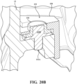
- an isolation and constraint system 148 may be used to isolate the housing 12 from the oscillations and pulsations caused by the orbiting scroll 66.
- the orbiting scroll 66 has a lower surface having a plurality of ring-shaped slots 66G (see above).
- the isolating sleeves 152 are integrally formed with a circular gasket or ring 156.
- each mounting pin 152 is full encapsulated by the flexible material using, for example, an over-molding process.
- the outer surface of the of the isolating sleeves 154 may be rubbed to assist with the isolation.
- a front cover 28 design includes an oil separator 96 and a three-reed reed mechanism 86. As discussed below, the design of the front cover 28, the fixed scroll 26 and the reed mechanism 86 define a multicavity pulsation muffler system.
- the multicavity pulsation muffler system 160 compressed refrigerant is released from the compression device 18 twice during a compression cycle.
- the compression device 18 includes two smaller secondary discharge ports are placed into (adjacent) two secondary discharge chambers, The secondary discharge chambers are downstream (in the discharge head) of the pressure drop from a central discharge port.
- the front cover 28 defines a parallel discharge path for refrigerant exiting the compression device 18 to the refrigerant outlet port 70.
- the compressor 10 includes the housing 12, the inverter module 44, the motor 54, and a compression device 18.
- the housing 12 defines an intake volume 74 and a discharge volume 82.
- the housing 12 has a generally cylindrical shape and a central axis 90C.
- the inverter module 44 is mounted inside the housing 12 and adapted to convert direct current electrical power to alternating current electrical power.
- the motor 54 is mounted inside the housing.
- the compression device 18 is coupled to the motor 54 for receiving the refrigerant from the intake volume 74 and compressing the refrigerant as the motor 54 is rotated.
- the compression device 18 has a central compression device outlet orifice 84A and first and second side compression device outlet orifices 84B for controllably releasing compressed refrigerant into the discharge volume 82 during a compression cycle.
- the compression device 18 is configured to release compressed refrigerant into the discharge volume 82 via the first and second side compression device outlet orifices 84B earlier in the compression cycle than refrigerant is released via the central discharge orifices 84A.
- oil separator 96 utilizes two parallel paths between the compression device 18 and the refrigerant outlet port 70 to reduce the net pressure drop while maintaining the reduction in this pulsation.
- refrigerant is released from the compression device 18 during each cycle, i.e., revolution (or orbit) of the orbiting scroll 66.
- refrigerant leaves the compression device 18 through the central orifice 84A and two side orifices 84B in the fixed scroll 26. Release of the refrigerant through the orifices, 84A, 84B is controlled by the central reed 87A and two side reeds 87B, respectively (see below).
- the side discharge chamber 82B are adjacent respective side reed 87B and receives intermixed pressurized refrigerant and oil from the compression device 18 through the side orifices 84B via respective reeds 87B.
- the pressure of the refrigerant in the chambers is: central discharge chamber 82A > side discharge chambers 82B > upper discharge chamber 82C.
- the oil separator 96 includes the central discharge chamber 82A and a lower baffle 132.
- the lower baffle 132 is chevron-shaped (inverted "v") and is located between the central chamber 82 and the oil reservoir 98.
- the shape of the lower baffle 132 creates an area of low pressure directly underneath. Intermixed oil and refrigerant enter the central discharge chamber 82A and is drawn downward by the low-pressure area. The oil and refrigerant are separated when the intermixed oil and refrigerant comes into contact with the upper surface of the lower baffle 132. The oil drops into the oil reservoir 98.
- Refrigerant may enter the side discharge chambers 82B via the side channels 100 and/or lower discharge channels 104. Refrigerant may then enter the upper discharge chamber 82B and then exit via the refrigerant outlet port 70.
- the reed mechanism 86 includes a discharge reed 86A and a reed retainer 86B which define the reeds 87A, 87B.
- the discharge reed 86A is used to tune the pressure at which the refrigerant is allowed to exit the compression device 18 through the central orifice 84A and two side orifices 84B, respectively.
- the electric compressor 10 includes a cylindrical sleeve 170 configured to constrain the motor section 16 within the outer housing 12.
- the cylindrical sleeve 170 has a tubular side wall 172 and a top cover 174 defining an interior cavity 176.
- the interior cavity 176 has an open end 178.
- the cylindrical sleeve 170 is configured to receive the motor section 16 or motor 54, together create a singular module assembly 210.
- the tubular side wall 172 and the top cover 174 may be composed from aluminum.
- the tubular side wall 172 and the top cover 174 are one piece.
- the cylindrical sleeve 170 may be cast as a single piece and then machined.
- the tubular side wall 172 and the top cover 174 are separate pieces and then fastened together by any suitable methods, such as welding or using clamps or other means.
- the electric compressor 10 is configured to compress a refrigerant.
- the electric compressor 10 includes the housing or outer housing 12, the refrigerant inlet port 68, the refrigerant outlet port 70, the inverter module 44, the motor 54, the drive shaft 90, the cylindrical sleeve 170, and a compression device 18.
- the housing 12 defines an intake volume 74 and a discharge volume 82 and has a generally cylindrical shape and a central axis 90C.
- the refrigerant inlet port 68 is coupled to the housing 12 and configured to introduce the refrigerant to the intake volume 74.
- the refrigerant outlet port 70 is coupled to the housing 12 and is configured to allow compressed refrigerant to exit the electric compressor 10 from the discharge volume 82.
- the inverter module 44 is mounted inside the housing 12 and is adapted to convert direct current electrical power to alternating current electrical power.
- the motor 54 is mounted inside the housing 12.
- the drive shaft 90 is coupled to the motor 54.
- the cylindrical sleeve 170 has a tubular side wall 172 and a top cover 174 defining an interior cavity 176.
- the interior cavity 176 has an open end 178.
- the cylindrical sleeve 170 is configured to receive the motor 54 therein and constrain the motor 54 within the interior cavity 176.
- the compression device 18 is coupled to the drive shaft 90 and receives the refrigerant from the intake volume and compresses the refrigerant as the drive shaft 90 is rotated by the motor 54.
- the clamping mechanisms 170 are discussed in further detail below.
- an assembly 210 includes a housing 12, a motor 54, a drive shaft 90, and a cylindrical sleeve 170.
- the housing 12 has a generally cylindrical shape and has a central axis 90C.
- the motor 54 is mounted inside the housing 12.
- the drive shaft 90 is coupled to the motor 54.
- the cylindrical sleeve 170 has a tubular side wall 172 and a top cover 174 defining an interior cavity 176.
- the interior cavity 176 has an open end 178.
- the cylindrical sleeve 170 is configured to receive the motor 54 therein and constrain the motor 54 within the interior cavity 176.
- the housing 12 defines an intake volume 74 and a discharge volume 82.
- the refrigerant inlet port 68 is coupled to the housing 12 and is configured to introduce the refrigerant to the intake volume 74.
- the refrigerant outlet port 70 is coupled to the housing 12 and is configured to allow compressed refrigerant to exit the electric compressor 12 from the discharge volume 82.
- the inverter section 14 includes an inverter housing 22, an inverter back cover 20, and an inverter module 44.
- the inverter back cover 20 is connected to the inverter housing 22 and forms an inverter cavity 30.
- the inverter module 44 is mounted inside the inverter cavity 30 and is adapted to convert direct current electrical power to alternating current electrical power.
- the cylindrical sleeve 170 includes a tubular side wall 172 and a top cover 174 forming an interior cavity 176 and an open end 178.
- the cylindrical sleeve 170 encloses the motor section 16 or motor 54.
- the cylindrical sleeve 170 constrains the motor 54 therein.
- the cylindrical sleeve 170 is constrained within the housing 22 of the electric compressor 10.
- the motor 54 includes a stator 58 having an outer diameter 180.
- the interior cavity 176 of the cylindrical sleeve 170 has an inner diameter 182.
- the outer diameter 180 of the stator 58 and the inner diameter 176 of the cylindrical sleeve 170 are configured to establish an interference fit therebetween.
- the interference between the outer diameter 180 of the stator 58 and the inner diameter 176 cylindrical sleeve 170 may be between 100 and 300 microns. In one embodiment, the interference may be approximately 200 microns.
- the slot 198 is configured to receive the at least one tab 196 to position the cylindrical sleeve 170 and motor 54 or motor section 16 to be positioned correctly within the housing 12.
- the slot 198 may be machined within the housing 12 to provide a tight or press-fit relationship between the at least one tab 196 and the corresponding slot 198.
- the housing 12 defines a cavity or inverter cavity 30.
- An inverter circuit 46 is located within the inverter cavity 30 and provides power to the motor 54 to control the rotational speed and direction of the motor 54 and the electric compressor 10 via a plurality of power terminals 188.
- the power terminals 188 extend from the motor cavity 56 to the circuit cavity 30 through apertures 190 in the top cover 174.
- Grommets or o-rings 192 may provide sealing around the power terminals 188.
- the pin 214 provides for easier assembly and rotational relationship between the motor section 16 within the housing 12.
- the rotational feature 194 allows for the cylindrical sleeve 170 to maintain concentricity within the motor 54 and locate and align the mating components of the compressor 10.
- the cylindrical sleeve 170 creates a module that allows for concentrical alignments between the sleeve 170, power terminals 188, and concentric alignment of the stator 60 to the circular drive shaft supporting member 218 for positioning the ball bearing 62 without distortion being created by the commonly used press-fit or shrink fit of the prior art by securing of the stator 60 directly into the housing 12, or additional locating steps as the compressor is being assembled.
- the concentric relationship is simplified by the module, and this further improves the NVH aspects of the compressor 10 or any out of axis rotational misalignments that may be created by the distortions, or assembly misalignments between the motor 54, to the drive shaft 90 and the rotational motion within the compression device 18.
- the first bearing 62 is positioned within the circular drive shaft supporting member 218 or assembled with the cylindrical sleeve 170 and motor section 16 or motor 54.
- the top cover 174 may be a separate component with the first bearing 62 being secured first within circular drive shaft supporting member 218, and the top cover 174 are assembled thereafter, and the motor section 16 secured into the cylindrical sleeve 170, create the integrated module assembly 210, that is then as a single unit mated to and secured within the inner diameter 186 of the motor cavity 56.
- the first bearing 62 within the circular drive shaft supporting member 218, combined and concentrically aligned with the cylindrical sleeve 170 and the motor section 16 or motor 54 may then be placed in the housing 12 and positioned at the correct orientation using the rotational feature 194. This arrangement ensures that all components are positioned for alignment within the housing and concentrically located within the housing 12 and correctly aligned for mating the other components of the compressor 10.
- the o-ring seal allows the upper surface of the top cover 174 between the inverter housing 22 when mated to remain refrigerant free to avoid any contact or current loses with creep of current into the refrigerant.
- this sealing may also create additional challenges since the inverter circuits 46 creates heat, and a flow or heat sink may be required to be in contact with the refrigerant to dissipate such heat. Alternatively, additional refrigerant flow may have to be directed through the windows 200, 202 in this embodiment.
- the tubular side wall 172 of the cylindrical sleeve 170 may include a refrigerant inlet window 202 to allow refrigerant to enter the intake volume 74.
- the inlet window 206 reduces the flow restrictions to the refrigerant entering into the compressor 10 and allow for additional flow of refrigerant to flow through the inverter electronics 46 and increase flow through the stator and rotor area of the drive motor. This may be advantageous for higher demand applications.
- this arrangement with the inlet windows 206 may allow for the slot 212 for the o-ring to be positioned to function more as a noise and vibration damper at any location along the length of the sleeve 170.
- the motor 54 has an end located adjacent the open end 178 of the cylindrical sleeve 170.
- the lower end of the cylindrical sleeve 170 has a lower concentric locating feature 204 configured to be received within a motor receiving portion of the housing 12 to assist in maintaining the motor and stator are concentric within the housing 12.
- An upper concentric locating feature 208 located at an upper end of the cylindrical sleeve 170 assists in maintaining the concentricity of the motor 54 within the housing 12, as well as the positioning of the bearing 62 within the electric compressor 10.
- the concentric locating features 204, 208 also help increase the isolation between the motor 54 and the housing 12, thereby improving noise, vibration, and harshness (NVH) characteristics of the electric compressor 10.
- NSH noise, vibration, and harshness
- the concentric locating features 204, 208 and the slot or channel 212 may be machined in the sleeve 170, and the length of the cylindrical sleeve 170 may then not impart a radial force and thereby reducing or eliminating the prior art issue with radial distortion.
- the present disclosure presents
- an electric compressor configured to compress a refrigerant, comprising:
- the electric compressor as set forth in embodiment 1, the motor including a stator having an outer diameter, wherein the outer diameter of the stator and an inner diameter inner of the cylindrical sleeve configured to establish an interference therebetween.
- the electric compressor as set forth in any one of embodiments 1 to 3, wherein the housing defines a circuit cavity configured to receive a circuit.
Landscapes
- Engineering & Computer Science (AREA)
- Mechanical Engineering (AREA)
- General Engineering & Computer Science (AREA)
- Applications Or Details Of Rotary Compressors (AREA)
- Compressor (AREA)
- Rotary Pumps (AREA)
Abstract
Description
- The present application is related to
US Patent Application Serial No. 18/147,928 , filed on same day as the present application, the entire contents of which are herein incorporated by reference. - The invention relates generally to an assembly, in particular to an electric compressor, and more particularly to an electric compressor that compresses a refrigerant using a scroll compression device.
- Compressors have long been used in cooling systems. In particular, scroll-type compressors, in which an orbiting scroll is rotated in a circular motion relative to a fixed scroll to compress a refrigerant, have been used in systems designed to provide cooling in specific areas. For example, such scroll-type compressors have long been used in the HVAC systems of motor vehicles, such as automobiles, to providing air-conditioning. Such compressors may also be used, in reverse, in applications requiring a heat pump. Generally, these compressors are driven using rotary motion derived from the automobile's engine.
- With the advent of battery-powered or electric vehicles and/or hybrid vehicles, in which the vehicle may be solely powered by a battery at times, such compressors must be driven or powered by the battery rather than an engine. Such compressors may be referred to as electric compressors.
- In addition to cooling a passenger compart of the motor vehicle, electric compressors may be used to provide heating or cooling to other areas or components of the motor vehicle. For instance, it may be desired to heat or cool the electronic systems and the battery or battery compartment, when the battery is being charged, especially during fast charging modes, as such generate heat which may damage or degrade. the battery and/or other system. It may also be used to cooling the battery during times when the battery is not being charged or used, as heat may damage or degrade the battery. Since the electric compressor may be run at various times, even when the motor vehicle is not in operation, such use, obviously, requires electrical energy from the battery, thus reducing the operating time of the battery.
- Additionally, electric compressors may run at a very high speed, e.g., 2,000 RPM (or higher). Such high speed may generate unwanted levels of noise.
- Generally, prior art electric compressors having a housing to contain the components of the compressors including a motor and a compression device driven by the motor to compress a refrigerant. The outer housing of the motor, which may be the stator of the motor, must be held in place relative to the housing the compressor. In some prior art compressors, a radial clamping force is applied along all, or part of, the outer diameter of the stator. The radial clamping force may be applied by an interference fit between the outer diameter of the stator and the inner diameter of the housing of 300 microns or more. This high radial clamping force may cause distortion in the geometry of the stator which may increase inefficiency in, and noise generated by, the compressor.
- Reference is made to
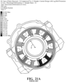
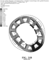
FIGS. 21A and22A , in which a stator is held in place relative to a compressor housing through a radial clamping force applied by an interference fit. The compressor may be assembled, for example, by heating the housing to increase the inner diameter thereof. The motor is then inserted within an inner cavity of the housing and the housing is allowed to cool to create the interference fit. As shown inFIGS. 21A-21B , this may cause a distortion or change in the radius or outer diameter of the stator.Fig 22A is not to scale. The distortions to the radius of the stator have been emphasized for illustration purposes. In the illustrated embodiment, the radius of the stator changed within a range of ~ (-91) microns to ~ (+49) microns. - In addition, electric power is generally supplied to the motor using a power circuit. The motor drives a mechanism to compress the refrigerant. As the refrigerant flows throughout the interior of the compressor including the interior of the motor, the electrical connections providing power to the motor must be electrically insulated from the interior of the compressor. For example, an encapsulating insulating material 2 (see
FIG. 21C ) may be applied to the junction between the power terminals of the motor and the electrical leads supplying power to the motor from the power circuit. Once the compressor is assembled, it may be difficult to access the interior cavity of the compressor in order to apply the encapsulating material. Further, in some embodiments, power may be supplied using a plurality of terminals located within a terminal block. This arrangement may require a hermetic seal within the housing that is complex and difficult to assemble (seeFIG. 21D ). - It is thus desirable to provide an electric compressor having high efficiency, low-noise and maximum operating life. The present invention is aimed at one or more of the problems or advantages identified above.
- In a first embodiment of the present invention, an electric compressor configured to compress a refrigerant is provided. The electric compressor includes a housing, a refrigerant inlet port, a refrigerant outlet port, an inverter module, a motor, a drive shaft, a cylindrical sleeve, and a compression device. The housing defines an intake volume and a discharge volume and has a generally cylindrical shape and a central axis. The refrigerant inlet port is coupled to the housing and configured to introduce the refrigerant to the intake volume. The refrigerant outlet port is coupled to the housing and is configured to allow compressed refrigerant to exit the electric compressor from the discharge volume. The inverter module is mounted inside the housing and is adapted to convert direct current electrical power to alternating current electrical power. The motor is mounted inside the housing. The drive shaft is coupled to the motor. The cylindrical sleeve has a tubular side wall and a top cover defining an interior cavity, The interior cavity has an open end and is configured to receive the motor therein and to constrain the motor within interior cavity. The compression device, coupled to the drive shaft, receives the refrigerant from the intake volume and compresses the refrigerant as the drive shaft is rotated by the motor.
- In a second embodiment of the present invention, an assembly having a housing, a motor, a drive shaft, and a cylindric sleeve is provided. The housing has a generally cylindrical shape and has a central axis. The motor is mounted inside the housing. The drive shaft is coupled to the motor. The cylindrical sleeve has a tubular side wall and a top cover defining an interior cavity. The interior cavity has an open end. The cylindrical sleeve is configured to receive the motor therein and constrain the motor within interior cavity.
- In a third embodiment of the present invention, an electric compressor having a central axis and being configured to compress a refrigerant, is provided. The compressor includes a housing, a refrigerant inlet port, a refrigerant outlet port, an inverter section, a motor section, a compression device and a plurality of clamping mechanisms.
- The housing defines an intake volume and a discharge volume. The refrigerant inlet port is coupled to the housing and is configured to introduce the refrigerant to the intake volume. The refrigerant outlet port is coupled to the housing and is configured to allow compressed refrigerant to exit the electric compressor from the discharge volume.
- The inverter section includes an inverter housing, an inverter back cover, and an inverter module. The inverter back cover is connected to the inverter housing and forms an inverter cavity. The inverter module is mounted inside the inverter cavity and is adapted to convert direct current electrical power to alternating current electrical power.
- The motor section includes a drive shaft and a motor. The drive shaft is located within the housing, has first and second ends, and defines a center axis. The motor is located within the housing to controllably rotate the drive shaft about the center axis.
- The compression device is coupled to the drive shaft for receiving the refrigerant from the intake volume and compressing the refrigerant as the drive shaft is rotated by the motor. The compression device includes a fixed scroll and an orbiting scroll. The fixed scroll is located within, and being fixed relative to, the housing. The orbiting scroll is coupled to the drive shaft. The orbiting scroll and the fixed scroll form compression chambers for receiving the refrigerant from the intake volume and for compressing the refrigerant as the drive shaft is rotated about the center axis.
- The cylindrical sleeve has a tubular side wall and a top cover defining an interior cavity. The interior cavity has an open end. The cylindrical sleeve is configured to receive the motor therein and constrain the motor within interior cavity.
- These and other features and advantages of the present invention will become more readily appreciated when considered in connection with the following detailed description and appended drawings.
-
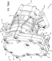
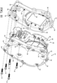
FIG. 1A is first perspective view an electric compressor, according to an embodiment of the present invention. -
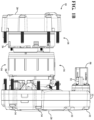
FIG. 1B is a partial view of the electric compressor ofFIG. 1A with a center housing removed. -
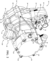
FIG. 2 is a second perspective view of the electric compressor ofFIG. 1A . -
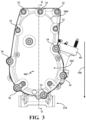
FIG. 3 is a first side view of the electric compressor ofFIG. 1A . -
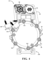
FIG. 4 is a second side view of the electric compressor ofFIG. 1A . -
FIG. 5 is a front view of the electric compressor ofFIG. 1A . -
FIG. 6 is a rear view of the electric compressor ofFIG. 1A . -
FIG. 7 is a top view of the electric compressor ofFIG. 1A . -
FIG. 8 is a bottom view of the electric compressor ofFIG. 1A . -
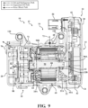
FIG. 9 is a first cross-sectional view of the electric compressor ofFIG. 1A . -
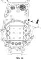
FIG. 10 is a second cross-sectional view of the electric compressor ofFIG. 1A . -
FIG. 11 is an exploded view of an inverter of the electric compressor ofFIG. 1A . -
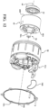
FIG. 12 is an exploded view of a portion of the electric compressor ofFIG. 1 , including a motor and drive shaft. -
FIG. 13 is an exploded view of a compression device of the electric compressor ofFIG. 1A . -
FIG. 14A is a first perspective view of a drive shaft ofFIG. 12 . -
FIG. 14B is a second perspective view of the drive shaft ofFIG. 14A . -
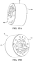
FIG. 15A is a first perspective view of a rotor and counterweights of the motor ofFIG. 12 . -
FIG. 15B is a second perspective view of the rotor and counterweights ofFIG. 15A . -
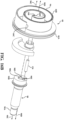
FIG. 16A is a first perspective view of a portion of the electric compressor ofFIG. 1 , including an orbiting scroll, drive pin and swing-link mechanism. -
FIG. 16B is a second perspective view of the portion of the electric compressor ofFIG. 16A . -
FIG. 16C is a perspective view of a plug of the compression device ofFIG. 13 . -
FIG. 16D is a second perspective view of the plug ofFIG. 16C . -
FIG. 16E is a cross-sectional view of the plug ofFIG. 16C . -
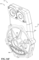
FIG. 16F is a perspective view of an inverter housing of the inverter ofFIG. 11 . -
FIG. 16G is a partial expanded view of the compression device ofFIG. 13 . -
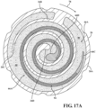
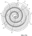
FIGS. 17A-17J are graphic representations of a fixed scroll and an orbiting scroll of a compression device of the electric compressor ofFIG. 1 , according to an embodiment of the present invention. -
FIG. 18A is a first perspective view of a portion of the compression device ofFIG. 13 , including a fixed scroll and an orbiting scroll. -
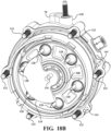
FIG. 18B is a second perspective view of the portion of the compression device ofFIG. 18A . -
FIG. 18C is a first perspective view of the fixed scroll of the compression device ofFIG. 13 . -
FIG. 18D is a second perspective view of the fixed scroll of the compression device ofFIG. 13 . -
FIG. 18E is a third perspective view of the fixed scroll of the compression device ofFIG. 13 . -
FIG. 18F is a perspective view of a reed mechanism associated with the compression device ofFIG. 13 . -
FIG. 18G is a cross-sectional view of the fixed scroll of the compression device ofFIG. 13 . -
FIG. 19A is a first perspective view of a front cover of an electric compressor forming an oil separator, according to an embodiment of the present invention. -
FIG. 19B is a second perspective view of the front cover ofFIG. 19A . -
FIG. 19C is a cross-sectional view of the front cover ofFIG. 19A . -
FIG. 20A is a partial view of an electric compressor with a cutaway view of the housing and an isolation and constraint system, according to an embodiment of the present invention. -
FIG. 20B is a partial view of an isolation and constraint system for use with an electric compressor, according to another embodiment of the present invention. -
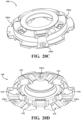
FIG. 20C is a first perspective view of a thrust body, according to an embodiment of the present invention. -
FIG. 20D is a second perspective view of the thrust body ofFIG. 20C . -
FIGS. 21A-21D are illustrations of a prior art compressor illustrating distortions in an outer diameter of a stator of a motor of the compressor. -
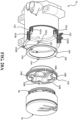
FIG. 22A is a perspective view of a compressor having a housing and a cylindrical sleeve partially enclosing a, according to an embodiment of the present invention. -
FIG. 22B is a perspective view of the cylindrical sleeve and a motor ofFIG. 22A . -
FIG. 22C is a second perspective view of the cylindrical sleeve and motor of the compressor ofFIG. 22A . -
FIG. 22D is a third perspective view of the cylindrical sleeve and motor of the compressor ofFIG. 22A illustrating a circuit cavity. -
FIG. 22E is a first perspective view of the housing of the compressor ofFIG. 22A . -
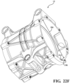
FIG. 22F is a second perspective view of the housing of the compressor ofFIG. 22A . -
FIG. 22G is a third perspective view of the housing of the compressor ofFIG. 22A . -
FIG. 22H is a first perspective view of a portion of the cylindrical sleeve of the compressor ofFIG. 22A . -
FIG. 22I is a second perspective view of a portion of the cylindrical sleeve of the compressor ofFIG. 22A . -
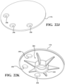
FIG. 22J is a first perspective view of a top portion of the cylindrical sleeve of the compressor ofFIG. 22A . -
FIG. 22K is a second perspective view of a portion of the cylindrical sleeve of the compressor ofFIG. 22A . -
FIG. 22L is an exploded view of a portion of the compressor ofFIG. 22A . -
FIG. 23A is a perspective view of a compressor having a housing and a cylindrical sleeve partially enclosing a, according to a second embodiment of the present invention. -
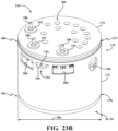
FIG. 23B is a perspective view of the cylindrical sleeve and a motor ofFIG. 23A . -
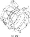
FIG. 23C is a first perspective view of the housing of the compressor ofFIG. 23A . -
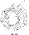
FIG. 23D is a second perspective view of the housing of the compressor ofFIG. 23A . -
FIG. 23E is a third perspective view of the housing of the compressor ofFIG. 23A . -
FIG. 23F is a first perspective view of a portion of the cylindrical sleeve of the compressor ofFIG. 23A . -
FIG. 23G is a second perspective view of a portion of the cylindrical sleeve of the compressor ofFIG. 23A . -
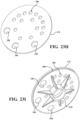
FIG. 23H is a first perspective view of a top portion of the cylindrical sleeve of the compressor ofFIG. 23A . - FIG. 231 is a second perspective view of a portion of the cylindrical sleeve of the compressor of
FIG. 23A . -
FIG. 23J is a partial cross-sectional view of the compressor ofFIG. 23A . - Referring to the
FIGS. 1A-20D , wherein like numerals indicate like or corresponding parts throughout the several views, anelectric compressor 10 having anouter housing 12 is provided. Theelectric compressor 10 is particularly suitable in a motor vehicle, such as an automotive vehicle (not shown). Theelectric compressor 10 may be used as a cooling device or as a heating pump (in reverse) to heat and/or cool different aspects of the vehicle. For instance, theelectric compressor 10 may be used as part of the heating, ventilation and air conditioning (HVAC) system in electric vehicles (not shown) to cool or heat a passenger compartment. In addition, theelectric compressor 10 may be used to heat or cool the passenger compartment, on-board electronics and/or a battery used for powering the vehicle while the vehicle is not being operated, for instance, during a charging cycle. Theelectric compressor 10 may further be used while the vehicle is not being operated and while the battery is not being charged to maintain, or minimize the degradation, of the life of the battery. In the illustrated embodiment, theelectric compressor 10 has a capacity of 36 cubic centimeters (cc). The capacity refers to the initial volume captured within the compression device as the scrolls of the compression device initially close or make contact (see below). It should be noted that theelectric compressor 10 disclosed herein is not limited to any such volume and may be sized or scaled to meet particular required specifications. - In the illustrated embodiment, the
electric compressor 10 is a scroll-type compressor that acts to compress a refrigerant rapidly and efficiently for use in different systems of a motor vehicle, for example, an electric or a hybrid vehicle. The electric compressor includes 10 aninverter section 14, amotor section 16, and a compression device (or compression assembly) 18 contained within theouter housing 12. Theouter housing 12 includes aninverter back cover 20, aninverter housing 22, acenter housing 24, and a front cover 28 (which may be referred to as the discharge head). Thecenter housing 24 houses themotor section 16 and thecompression device 28. - In one aspect of the present invention, the
electric compressor 10 includes acylindrical sleeve 170 encompassing themotor section 16 configured to constrain themotor section 16 within the outer housing 12 (see below). - The
inverter back cover 20, theinverter housing 22, thecenter housing 24, and thefront cover 28 may be composed from machined aluminum. Theinverter 10 may be mounted, for example, within the body of a motor vehicle, via a plurality of mount points 120. - The
inverter back cover 20 and theinverter housing 22 form aninverter cavity 30. Theinverter back cover 20 is mounted to theinverter housing 22 by a plurality ofbolts 32. Theinverter back cover 20 and theinverter housing 22 are mounted to thecenter housing 24 by a plurality ofbolts 34 which extend throughapertures 36 in theinverter back cover 20 andapertures 38 in theinverter housing 22 and are threaded into threaded apertures 40 in thecenter housing 24. Aninverter gasket 42, positioned between theinverter back cover 20 and theinverter housing 22 keeps moisture, dust, and other contaminants from theinternal cavity 30. Amotor gasket 54B is positioned between theinverter housing 22 and thecenter housing 24 to provide and maintain a refrigerant seal to the environment. - With reference to
FIG. 11 , aninverter module 44 mounted within theinverter cavity 30 formed by theinverter back cover 20 and theinverter housing 22. Theinverter module 44 includes aninverter circuit 46 mounted on a printedcircuit board 48, which is mounted to theinverter housing 22. Theinverter circuit 46 converts direct current (DC) electrical power received from outside of theelectric compressor 10 into three-phase alternating current (AC) power to supply/power the motor 54 (see below). Theinverter circuit 46 also controls the rotational speed of theelectric compressor 10. High voltage DC current is supplied to theinverter circuit 46 via ahigh voltage connector 50. Low voltage DC current to drive theinverter circuit 46, as well as control signals to control operation of theinverter circuit 46, and themotor section 16, is supplied via alow voltage connector 52. - The
center housing 24 forms a motor cavity 56. Themotor section 16 includes amotor 54 located within the motor cavity 56. The motor cavity 56 is formed by amotor side 22A of theinverter housing 22 and aninside surface 24A of thecenter housing 22. With specific reference toFIG. 12 , themotor 54 is a three-phase AC motor having astator 60. Thestator 60 has a generally hollow cylindrical shape with six individual coils (two for each phase). Thestator 60 is contained within, and mounted to, themotor housing 22 and remains stationary relative to themotor housing 22. - The
motor 54 includes arotor 60 located within, and centered relative to, thestator 58. Therotor 60 has a generally hollow cylindrical shape and is located within thestator 60. Therotor 60 has a number of balancingcounterweights motor 54 as themotor 54 drives thecompression device 18 and may be machined from brass. - Power is supplied to the
motor 54 via a set ofterminals 54A which are sealed from the motor cavity 56 by an O-ring 54B. - A
drive shaft 90 is coupled to therotor 60 and rotates therewith. In the illustrated embodiment, thedraft shaft 90 is press-fit within a center aperture 60C of therotor 60. Thedrive shaft 90 has afirst end 90A and asecond end 90B. Theinverter housing 22 includes a first driveshaft supporting member 22B located on the motor side of theinverter housing 22. Afirst ball bearing 62 located within an aperture formed by the first driveshaft supporting member 22 supports and allows the first end of thedrive shaft 90 to rotate. Thecenter housing 24 includes a second driveshaft supporting member 24A. A second ball bearing 64 located within an aperture formed by the second driveshaft supporting member 24A allows thesecond end 90B of thedrive shaft 90 to rotate. In the illustrated embodiment, the first and second ball bearing 62, 64 are press-fit with the apertures formed by the first driveshaft supporting member 22 of theinverter housing 22 and the second driveshaft supporting member 24A of thecenter housing 24, respectively. - As stated above, the
electric compressor 10 is a scroll-type compressor. Thecompression device 18 includes the fixedscroll 26 and anorbiting scroll 66. The orbitingscroll 66 is fixed to the second end of therotor 60B. Therotor 60 with thedrive shaft 90 rotate to drive the orbitingscroll 66 motion under control of theinverter module 44 rotate. - With reference to
FIGS. 14A, 14B ,16A and16B , thedrive shaft 90 has acentral axis 90C around which therotor 60 and thedrive shaft 90 are rotated. The orbitingscroll 66 moves about thecentral axis 90C in an eccentric orbit, i.e., in a circular motion while the orientation of the orbitingscroll 66 remains constant with respect to the fixedscroll 26. The center of the orbitingscroll 66 is located along an offsetaxis 90D of thedrive shaft 90 defined by an orbiting scroll aperture (or drive pin location) 90E (seeFIG. 14A ) located at thesecond end 90D of thedrive shaft 90. As thedrive shaft 90 is rotated by themotor 54, the orbitingscroll 66 follows the motion of theorbiting scroll aperture 90E through thedrive pin 126 and the drive hub of theswinglink mechanism 124 and bearing 108 as thedrive shaft 90 is rotated about the central axis 60C. - With specific reference to
FIGS. 1 ,2 and9 , intermixed refrigerant and oil (at low pressure) enters theelectric compressor 10 via arefrigerant inlet port 68 and exits the electric compressor 10 (at high pressure) viarefrigerant outlet port 70 after being compressed by thecompression device 18. As shown in the cross-sectional view ofFIG. 9 , the refrigerant follows therefrigerant path 72 through theelectric compressor 10. As shown, refrigerant enters therefrigerant inlet port 68 and enters an intake volume 74 formed between themotor side 22A of theinverter housing 22 and thecenter housing 24 adjacent therefrigerant inlet port 68. Refrigerant is then drawn through themotor section 16 and enters a compression intake volume 76 formed between an internal wall of the fixedscroll 26 and the orbiting scroll 66 (demonstrated byarrow 92 inFIG. 14A ). - The fixed
scroll 26 is mounted within thecenter housing 24. As shown inFIGS. 9 and13 , the fixedscroll 26 has a fixedscroll base 26A and a fixedscroll lap 26B extending away from the fixedscroll base 26A towards the orbitingscroll 66. As shown inFIGS. 16A-16B , the orbitingscroll 66 has anorbiting scroll base 66A and anorbiting scroll lap 66B extending from theorbiting scroll base 66A towards the fixedscroll 26. Thelaps tail end respective scroll respective center end - Respective tip seals 94 are located within a
slot 26E, 66E located at a top surface of the fixedscroll 26 and the orbitingscroll 66, respectively. The tip seals 94 are comprised of a flexible material, such as a Polyphenylene Sulfide (PPS) plastic. When assembled, the tip seals 94 are pressed against theopposite base 26Aslots 26E 66E, are longer than the length of the tip seals 94 to provide room for adjustment/movement along the length of the tip seals 94. - With reference to
FIGS. 17A-17I , refrigerant enters thecompression device 12 from the compression intake volume 76. InFIGS. 17A-17I , a cross-section view of the fixedscroll 26 shown and the top of the orbitingscroll 66 are shown. - As discussed in detail below, the fixed
scroll lap 26A and theorbiting scroll lap 66Aform compression chambers 80 in which low or unpressurized (saturation pressure) refrigerant enters from thecompression device 12. As theorbiting scroll 66 moves to enable thecompression chambers 80 to be closed off and the volume of thecompression chambers 80 is reduced to pressurize the refrigerant. At any one time during the cycle, one ormore compression chambers 80 are at different stages in the compression cycle. The below description relates just to one set ofcompression chambers 80 during a complete cycle of theelectric compressor 10. - The refrigerant enters the
compression chambers 80 formed between the orbitingscroll lap 66A and the fixedscroll lap 26A. During a cycle of thecompressor 10, the refrigerant is transported towards the center of these chambers. The orbitingscroll 66 orbits in a circular motion indicated byarrow 78 formed by the relative position of the orbitingscroll 66 relative to the fixedscroll 26 is shown during one cycle of theelectric compressor 10. - In
FIG. 17A , the position of the orbitingscroll 66 at the beginning of a cycle is shown. As shown, in this initial position, the tail ends 16B, 66B are spaced apart from theother scroll lap 66B 16B. At this point, thecompression chambers 80 are open to the compression intake volume 76 allowing refrigerant under low pressure to fill thecompression chambers 80 from the compression intake volume 76. As theorbiting scroll 66 moves alongpath 78, the space between the tail ends 16A, 66A and theother scroll compression chambers 80 are closed off from the compression intake volume 76 (FIGS. 17B-17E ). As theorbiting scroll 66 continues to move along 78, the volume of thecompression chambers 80 is further reduced, thus pressurizing the refrigerant in both compression chambers 80 (FIGS. 17F-H ). As shown inFIGS. 17I -18J, as the orbitingscroll 66 continues to orbit, the twocompression chambers 80 are combined into a single volume. This volume is further reduced until the pressurized refrigerant is expelled from the compression device 18 (see below) - As discussed below, the refrigerant enters chambers formed between the walls of the orbiting
scroll 66 and the fixedscroll 26. During the cycle of thecompressor 10, the refrigerant is transported towards the center of these chambers. The orbitingscroll 66 orbits or moves in a circular motion indicated byarrow 78 formed by the relative position of the orbitingscroll 66 relative to the fixedscroll 26 is shown during one cycle of theelectric compressor 10. - Returning to
FIG. 1 , thefront cover 28 forms adischarge volume 82. Thedischarge volume 82 is in communication with therefrigerant output port 70. As discussed in more detail below, pressurized refrigerant leaves thecompression device 18 through acentral orifice 84A and twoside orifices 84B in the fixed scroll 26 (seeFIGS. 18C and18E ) The release of pressurized refrigerant is controlled by areed mechanism 86. In the illustrated embodiment, thereed mechanism 86 includes three reeds: acentral reed 87A and twoside reeds 87B corresponding to thecentral orifice 84A and the twoside orifices 84B (see below). - As shown in
FIGS. 18D and18E , in the illustrated embodiment, thereed mechanism 86 includes adischarge reed 86A and areed retainer 86B. Thedischarge reed 86A is made from a flexible material, such as steel. The characteristics, such as material and strength, are selected to control the pressure at which the pressurized refrigerant is released from thecompression device 18. Thereed retainer 86B is made from a rigid, inflexible material such as stamped steel. Thereed retainer 86 controls or limits the maximum displacement of thedischarge reed 86A relative to the fixedscroll 26. Generally, oil is directed rearward through themotor section 16, providing lubrication and cooling to the rotating components of theelectric compressor 10, such as therotor 60, thedrive shaft 90 and allbeatings motor 54 by the rotation of therotor 60. From there, oil enters the interior of themotor 54 to lubricate thesecond ball bearing 64 and the oil by the rotational forces within themotor section 16 may impact against themotor side 22A of theinverter housing 22. The oil is further directed by themotor side 22A into theball bearing 62, further discussed below - In the illustrated embodiment, the
read mechanism 86 is held or fixed in place via a separate fastener 89. As shown inFIGS. 18E and 18F , thereed mechanism 86 incudes a plurality of apertures 86C which are configured to receive associated posts 83A on the fixedscroll 26. As shown inFIG. 18E , the back surface of the fixedscroll 26 includes a bezel 83B surrounding the orifices 84 which assists in tuning the pressure at which refrigerant exits thecompression device 18. Additionally, a debris collection slot 83C collects debris near theorifices reed mechanism 86. - As shown in
FIG. 9 , the path of refrigerant through the electric compressor is indicated by dashedarrow 72. - The
electric compressor 10 utilizes oil (not shown) to provide lubrication to the between the components of thecompression device 18 and themotor 54, for example, between the orbitingscroll 66 and the fixedscroll 26 and within theball bearings compression device 18 and themotor 54 and exits thecompression device 18 via the orifice 84. As discussed in more detail below, the oil is separated from the compressed refrigerant within thefront cover 28 and is returned to thecompression device 18. - An oil separator 96 facilitates the separation of the intermixed oil and refrigerant. In the illustrated embodiment, the oil separator 96 is integrated within the
front cover 28. Thefront cover 28 further defines anoil reservoir 98 which collects oil from the oil separator 96 before the oil is recirculated through themotor 54 and motor cavity 56 and thecompression device 18. In use, theelectric compressor 10 is generally orientated as shown inFIGS. 3-5 , such that gravity acts as indicated byarrow 106 and oil collects within theoil reservoir 98. - With reference to
FIG. 9 , the general path oil travels from the bottom of theelectric compressor 10 through thecompression device 18, out the orifice 84 to thedischarge volume 82 of thefront cover 28 and back to thecompression device 18 is shown byarrow 88. - In the illustrated embodiment, the
front cover 28 is mounted to thecenter housing 24 by a plurality ofbolts 122 inserted through respective apertures therein and threaded into apertures in thecenter housing 24. A fixed head gasket 110 and a rear heard gasket 112, are located between thecenter housing 24 and the fixedscroll 26 to provide sealing. - An oil separator 96 facilitates the separation of the intermixed oil and refrigerant. Generally, the oil separator 96 only removes some of the oil within the intermixed oil and refrigerant. The separator oil is stored in an oil reservoir and cycled back through the
compression device 18, where the oil is mixed back in with the refrigerant. - In the illustrated embodiment, the oil separator 96 is integrated within the
front cover 28. Thefront cover 28 further defines anoil reservoir 98 which collects oil from the oil separator 96 before the oil is recirculated through themotor 54 and motor cavity 56 and thecompression device 18. In use, theelectric compressor 10 is generally orientated as shown inFIGS. 3-5 , such that gravity acts as indicated byarrow 106 and oil collects within theoil reservoir 98. With reference toFIG. 9 , the general path oil travels from the bottom of theelectric compressor 10 through thecompression device 18, out the orifice 84 to thedischarge volume 82 of thefront cover 28 and back to thecompression device 18 is shown byarrow 88. As shown, the oil is drawn back up into thecompression device 18 where the oil mixed back into or with the refrigerant. - As stated above, refrigerant, which is actually a mixture of refrigerant and oil enters the
electric compressor 10 via therefrigerant inlet port 70. The intermix of oil and refrigerant is drawn into themotor section 16, thereby providing lubrication and cooling to the rotating components of theelectric compressor 10, such as therotor 60, the drive shaft 90.Oil and refrigerant enters the interior of themotor 54 to lubricate thesecond ball bearing 64 and the oil by the rotational forces within themotor section 16. may impact against themotor side 22A of theinverter housing 22. The refrigerant and oil is further directed by themotor side 22A into theball bearing 62, further discussed below. - With specific reference to
FIGS. 13-18B , in a first aspect of theelectric compressor 10 of the disclosure, anelectric compressor 10 includes aswing link mechanism 124 and thedrive shaft 90 has aconcentric protrusion 126. In one embodiment, theconcentric protrusion 126 is integrally formed with thedrive shaft 90. As discussed below, the swing-link mechanism 124 is used to rotate theorbiting scroll 66 in an eccentric orbit about thedrive shaft 90. - In the prior art, the drive shaft is coupled to a swing-link mechanism by a drive pin and a separate eccentric pin, both of which are pressing into the drive shaft. The drive pin is used to rotate the
swing link mechanism 124 which moves the orbitingscroll 66 along its eccentric orbit. The drive pin and the eccentric pin are inserted into respective apertures in the end of the drive shaft. The eccentric pin is used to limit articulation of the orbitingscroll 66 is the orbitingscroll 66 travels along the eccentric orbit. Neither the drive pin, nor the eccentric pin, are located along the central axis of the drive shaft. As the drive shaft is rotated, the drive pin and the eccentric pin are placed under considerable stress. This, both pins are composed from a hardened material, such as SAE 52100 bearing steel. In addition, the eccentric pin may require an aluminum bushing or other slide bearing to prevent damage to the eccentric pin, as the eccentric pin is used to limit the radial movement of the eccentric orbit of the orbitingscroll 66. Also, the prior art eccentric pin requires additional machining on the face of thedrive shaft 90, including precise apertures for the drive pin, and eccentric pin. - As discussed in more detail below, the eccentric pin of the prior art is replaced with a
concentric protrusion 90F. - In the illustrated embodiment, the scroll-type
electric compressor 10 includes thehousing 12, therefrigerant inlet port 68, therefrigerant outlet port 70, thedrive shaft 90, theconcentric protrusion 90F, themotor 54, thecompression device 18, theswing link mechanism 124, adrive pin 126 and aball bearing 108. Thehousing 12 defines the intake volume 74 and thedischarge volume 82. Therefrigerant inlet port 68 is coupled to thehousing 12 and is configured to introduce the refrigerant to the intake volume 74. Therefrigerant outlet port 70 is coupled to thehousing 12 and is configured to allow compressed refrigerant to exit the scroll-typeelectric compressor 10 from thedischarge volume 82. Thedrive shaft 90 is located within thehousing 12 and has first and second ends 90A, 90B. Thedrive shaft 90 defines, and is centered upon, acenter axis 90C. - The
concentric protrusion 90F is located at thesecond end 90B of thedrive shaft 90 and is centered on thecenter axis 90C. Theconcentric protrusion 90F and extends away from thedrive shaft 90 along thecentral axis 90C. Theconcentric protrusion 90F includes adrive pin aperture 90E. Themotor 54 is located within thehousing 12 and is coupled to thedrive shaft 90 to controllably rotate thedrive shaft 90 about thecenter axis 90C. Thedrive pin 126 is located within thedrive pin aperture 90E and extends away from thedrive shaft 90. Thedrive pin 126 is parallel to theconcentric protrusion 90F. - The
concentric pin 90F may further include an undercut 90G, and the outer surface may be surface hardened or after treated with a coating or bearing surface. Theconcentric pin 90F may be further machined simultaneously with thedrive shaft 90. - As explained above, the
compression device 18 includes the fixedscroll 26 and the orbitingscroll 66. The fixedscroll 26 is located within, and being fixed relative to, thehousing 12. The orbitingscroll 66 is coupled to thedrive shaft 90. The orbitingscroll 66 and the fixedscroll 26 form compression chambers 80 (see above) for receiving the refrigerant from the intake volume 74 and for compressing the refrigerant as thedrive shaft 90 is rotated about thecenter axis 90C. The orbitingscroll 66 has an innercircumferential surface 66E. - The swing-
link mechanism 124 is coupled to thedrive shaft 90 and has first andsecond apertures concentric protrusion 90F and thedrive pin 126. The swing-link mechanism 124 further includes an outercircumferential surface 124C. - The
ball bearing 108 is positioned between, and adjacent to each of, the innercircumferential surface 66E of the orbitingscroll 66 and the outercircumferential surface 124C of the swing-link mechanism 124. Thedrive shaft 90,drive pin 126, orbitingscroll 66 and swing-link mechanism 124 are arranged to cause theorbiting scroll 66 to rotate about thecentral axis 90C in an eccentric orbit. - In one embodiment, the
concentric protrusion 90F is integrally formed with thedrive shaft 90. Thedrive shaft 90,concentric protrusion 90F, and swing-link mechanism 124 may be machined from steel. Theconcentric protrusion 90F being formed simultaneously and within the same machining operation with thedrive shaft 90 further increases manufacturing efficiencies. - The expanded view of a portion of the
compression device 18 illustrated inFIG. 16G , further illustrates theconcentric protrusion 90F. Theconcentric protrusion 90F interacts and guides the swink-link mechanism 124. Theconcentric protrusion 90F is sized and machined with a controlled tolerance with thefirst aperture 124A to create a controlled gap that limits the radial movement of the eccentric orbit of the orbitingscroll 66. Unlike the prior art, theconcentric protrusion 90F does not require a second pin, or any additional machining operations. Theconcentric protrusion 90F further co-operates with the guidance pins 128 and the slots 66G on a lower surface 66F of the orbitingscroll 66, further discussed below. - The scroll-type
electric compressor 10 includes aninverter section 14, amotor section 16, and thecompression device 18. Themotor section 16 includes amotor housing 54 that defines a motor cavity 56. Thecompression section 18 includes the fixedscroll 26. Thehousing 12 is formed, at least in part, the fixedscroll 26 and thecenter housing 24. - With specific reference to 13, 16B, and 18A-18F in the illustrated embodiment, the orbiting
scroll 66 has a lower surface 66F. The lower surface 66F has a plurality of ring-shaped slots 66G. Thecenter housing 24 includes a plurality of articulatingguidance pin apertures 128. The guidance pins 128 are located within the guidance pin apertures 66G and extend towards thecompression device 18 and into the ring-shaped slots 66G. The guidance pins 128 are configured to limit articulation of the orbitingscroll 66 as the orbitingscroll 66 orbits about thecentral axis 90C. In one embodiment, each of the ring-shaped slots 66G includes aring sleeve 118. Athrust plate 130 is located between the fixedscroll 26 and a thrust body 150 (see below) and provides a wear surface therebetween. - In the illustrated embodiment, the
electric compressor 10 includes a multicavity pulsation muffler system 160 and an oil separator 96 which may be located in thedischarge volume 82 and integrally formed with the discharge head orfront cover 28. As discussed above, oil is used to provide lubrication between the moving components of theelectric compressor 10. During operation, the oil and the refrigerant become mixed. The oil separator 96 is necessary to separate the intermixed oil and refrigerant before the refrigerant leaves theelectric compressor 10. - Generally, refrigerant is released from the
compression device 18 during each cycle, i.e., revolution (or orbit) of the orbitingscroll 66. In the illustrated embodiment, refrigerant leaves thecompression device 18 through thecentral orifice 84A and twoside orifices 84B in the fixedscroll 26. Release of the refrigerant through the orifices, 84A, 84B is controlled by thecentral reed 87A and twoside reeds 87B, respectively. The multicavity pulsation muffler system 160 and the oil separator 96 are described in more detail below. - The
electric compressor 10 may include a scroll bearing oil injection orifice. As discussed above, thecompression device 18 of the present disclosure includes aball bearing 108. In the illustrated embodiments, theball bearing 108 is located between the swing-link mechanism 124 and the orbitingscroll 66. However, as a result of the location of theball bearing 108 within thecompression device 18, there may be limited oil delivery to theball bearing 108 resulting in reduced durability. As shown inFIG. 9 , theoil orifice 138 allows oil (and refrigerant) to travel from thedischarge chamber 82 to theball bearing 108 along the path 73 (which may be referred to as the "nose bleed" path). - The scroll-type
electric compressor 10 may include ahousing 12, arefrigerant inlet port 68, arefrigerant outlet port 70, an inverter module 144, amotor 54, adrive shaft 90 and acompression device 18. Thehousing 12 defines an intake volume 74 and adischarge volume 82. Therefrigerant inlet port 68 is coupled to thehousing 12 and is configured to introduce the refrigerant to the intake volume 74. Therefrigerant outlet port 70 is coupled to thehousing 12 and is configured to allow compressed refrigerant to exit the scroll-typeelectric compressor 10 from thedischarge volume 82. The inverter module 144 is mounted inside thehousing 12 and adapted to convert direct current electrical power to alternating current electrical power. Themotor 54 is mounted inside thehousing 12. Thedrive shaft 90 is coupled to themotor 54. Thecompression device 18 receives the refrigerant from the intake volume 74 and compresses the refrigerant as thedrive shaft 90 is rotated by themotor 54. Thecompression device 18 includes a fixedscroll 26, an orbitingscroll 66, a swing-link mechanism 124, aball bearing 108 and apin 136. - The fixed
scroll 26 is located within, and is fixed relative to, thehousing 12. The orbitingscroll 66 is coupled to thedrive shaft 90. The orbitingscroll 66 and the fixedscroll 26form compression chambers 80 for receiving the refrigerant from theintake volume 72 and compressing the refrigerant as thedrive shaft 90 is rotated about thecenter axis 90C. The orbitingscroll 66 has a first side (or the lower surface) 66F and a second side (or upper surface) 66G. The orbitingscroll 66 has anoil aperture 140 through the orbitingscroll 66 from the first side 66F to the second side 66G. - The swing-
link mechanism 124 is coupled to thedrive shaft 90. Theball bearing 108 is positioned between and adjacent to each of the orbitingscroll 66 and the swing-link mechanism 124. Thedrive shaft 90, orbitingscroll 66 and swing-link mechanism 124 are arranged to cause theorbiting scroll 66 to orbit thecentral axis 90C in an eccentric orbit. - As shown in
FIGS. 16B-16E , the tip of the orbitingscroll 66 includes aplug 136 and has anoil orifice 138. Theplug 136 may be press fit within theoil aperture 140 of the orbitingscroll 66. Theoil orifice 138 is configured to allow oil with a controlled flow rate or compressed refrigerant to pass through the orbitingscroll 66 to theball bearing 108. - The size of the
oil orifice 138 may be tuned to the specifications of theelectric compressor 10. For example, given the specifications of theelectric compressor 10, the diameter of theoil orifice 138 may be chosen such that only oil is allowed to pass through and to limit the equalization of pressure between the first and second sides of the orbitingscroll 66. By using aseparate plug 136, rather than machining theoil orifice 138 directly in theorbiting scroll 66, manufacturing efficiencies may be achieved. And theplug 136 may have anoil orifice 138 that is specifically designed and tuned to allow for oil flow and refrigerant flow to increase or decrease depending on the diameter and geometry of theoil orifice 138. - As shown in
FIGS. 16D-16E , in one embodiment, theoil orifice 138 may have afirst bore 138A and asecond bore 138B, wherein a diameter of thefirst bore 138A is less than a diameter of thesecond bore 138B. For example, in one application of this embodiment thefirst bore 138A has an approximate diameter of 0.3 mm. Thesecond bore 138B has a diameter greater than the diameter of thefirst bore 138A and is only used to shorten the length of thefirst bore 138A. The flow of the oil and coolant is designed to provide thermal and lubricant to theball bearing 108 supporting the radial forces created by the eccentric orbit of the orbitingscroll 66. - Further, as discussed above, the orbiting
scroll 66 has anorbiting scroll base 66A and anorbiting scroll lap 66B. Theorbiting scroll lap 66B may have an orbitingscroll tail end 66C and an orbitingscroll center end 66D. As shown, theoil aperture 140 is located within the orbitingscroll center end 66D. Theplug 136 may be secured into theoil aperture 140, by press fit or any other method that will secure theplug 136. - As shown in
FIG. 9 , theoil orifice 138 allows oil (and refrigerant) to travel from thedischarge chamber 82 to theball bearing 108 along the path 73 (which may be referred to as the "nose bleed" path). - The
electric compressor 10 may include one or more bearing oil communication holes. As discussed above, in the illustrated embodiment, adrive shaft 90 is rotated by themotor 54 to controllably actuate thecompression device 18. Thedrive shaft 90 has afirst end 90A and a second and 90B. Thehousing 10 of theelectric compressor 10 forms a first driveshaft supporting member 22B and a second driveshaft support member 24A. In the illustrated embodiment, the first driveshaft supporting member 22B is formed in amotor side 22 of theinverter housing 22A and the second driveshaft supporting member 24A is formed within thecenter housing 24. First andsecond ball bearings shaft support members - The location of the first drive
shaft supporting members 22B is not a flow-through area for refrigerant (and oil). This may result in a low lubricating condition and affect the durability of theelectric compressor 10. - As shown in
FIG. 16F , the firstdrive supporting member 22B may include one ormore holes 22C to allow oil to enter the firstdrive support member 22B and lubricate thefirst ball bearing 62. - In the illustrated embodiment, the scroll-type
electric compressor 10 includes ahousing 12, afirst ball bearing 62, a second ball bearing 64, arefrigerant inlet port 68, arefrigerant outlet port 70, aninverter module 44, amotor 54, adrive shaft 90, and acompression device 18. - The
housing 12 defines an intake volume 74 and adischarge volume 82 and includes first and second driveshaft supporting members first ball bearing 62 is located within the first driveshaft supporting member 22B. The first driveshaft support member 22B of thehousing 12 includes one or moreoil communication holes 22C for allowing oil to enter thefirst ball bearing 62. - The second ball bearing 64 is located within the second drive
shaft supporting member 24A. Therefrigerant inlet port 68 is coupled to thehousing 12 and is configured to introduce the refrigerant to the intake volume 74. Therefrigerant outlet port 70 is coupled to thehousing 12 and is configured to allow compressed refrigerant to exit the scroll-typeelectric compressor 10 from thedischarge volume 82. The inverter module 144 is mounted inside thehousing 12 and is adapted to convert direct current electrical power to alternating current electrical power. Themotor 54 is mounted inside thehousing 12. Thedrive shaft 90 is coupled to themotor 54. Thedrive shaft 90 has afirst end 90A and asecond end 90B. Thefirst end 90A of thedrive shaft 90 is positioned within thefirst bearing 62 and thesecond end 90B of thedrive shaft 90 is positioned within thesecond bearing 64. Thecompression device 18 receives the refrigerant from the intake volume 74 and compresses the refrigerant as thedrive shaft 90 is rotated by themotor 54. As discussed above, in the illustrated embodiment, the first driveshaft support member 22 may be formed on themotor side 22A of theinverter housing 22. - The rotational movement within the
motor section 16 of thecompression device 18 creates a flow path and movement to the oil from theoil reservoir 98, as shown byarrows 88 inFIG. 9 . As shown the oil flows from theoil reservoir 98 toward themotor section 16 and continues toward thestator 58 androtor 60. The rotational motion of the orbiting scroll, rotor and drive shaft pulls the oil upward to mix with the inlet flow of therefrigerant path 72. The rotational movement of therotor 60 and driveshaft 90 will further propel the oil against themotor side 22A of theinverter housing 22. Themotor side 22A surface further includes a series of ribs 22D, shown inFIG 16F . The ribs 22D provide the needed rigidity for supporting the first driveshaft support member 22 and allow for a ridged backing and pocket to secure thefirst bearing 62. Theinverter housing 22 nay further defines an oil cavity (not shown) where the oil collected between the ribs 22D is directed by gravity downward and into the oil. The ribs 22D and the sloped surface of themotor side 22A cooperate to capture and direct the oil splashed or propelled against themotor side 22A by therotor 60 or driveshaft 90, to assist in increasing the oil flow into the oil cavity 22E andfirst bearing 62.FIG 16F illustrates twocommunication holes 22C, but it is appreciated additional or less than 2oil communication hole 22C may be included above and between the ribs 22D on themotor side 22A of theinverter housing 22. For example in the illustrated embodiment the hole is 3.5 mm in diameter and themotor side 22A includes a sloping wall between the ribs 22D. In addition, themotor side 22A may include a outeroil collection area 22 - The scroll-type
electric compressor 10 of the present invention may include adomed inverter cover 20. The scroll-typeelectric compressor 10 includes thehousing 12, therefrigerant inlet port 68, therefrigerant outlet port 70, theinverter module 44, themotor 54, thedrive shaft 90, thecompression device 18 and theinverter cover 20. Thehousing 12 defines theintake volume 70 and thedischarge volume 82. Thehousing 12 has a generally cylindrical shape and thecentral axis 90C. Therefrigerant inlet port 68 is coupled to thehousing 12 and is configured to introduce the refrigerant to theintake volume 70. Therefrigerant outlet port 82 is coupled to thehousing 12 and is configured to allow compressed refrigerant to exit the scroll-typeelectric compressor 10 from thedischarge volume 82. - The
inverter module 44 is mounted inside thehousing 12 and adapted to convert direct current electrical power to alternating current electrical power. Themotor 54 is mounted inside thehousing 12. Thedrive shaft 90 is coupled to themotor 54. Thecompression device 18 is coupled to thedrive shaft 90 and is configured to receive the refrigerant from the intake volume and to compress the refrigerant as thedrive shaft 90 is rotated by themotor 54. - As discussed above, the
compression device 18 may rotate at a high speed (> 2,000 RPM) which may create undesirable noise, vibration, and harshness (NVH) and low durability conditions. In the prior art, theinverter cover 20 is generally flat and tends to amplify and/or focus, the vibrations from thecompression device 18. - To disperse vibrations rather than focus, the vibrations from the
compression device 18, the inverter back cover 20 of the electric scroll-like compressor 10 of the fifth aspect of the disclosure is provided with a generally curved or domed profile. - As shown in the FIGS., specifically
FIGS. 1 ,3 and6 , theinverter cover 20 is located at one end of the scroll-typeelectric compressor 10 and includes a first portion 20A and asecond portion 20B. The first portion 20A includes an apex orapex portion 20C and is generally perpendicular to thecentral axis 90C and has an apex 20C and anouter perimeter 20D. The first portion 20A has a relatively domed-shaped such that theinverter cover 20 has a curved profile from the apex 20C towards theouter perimeter 20D. The amount and location of the curvature may be dictated or limited by other considerations, such as packaging constraints, i.e., the space in which the electric scroll-type compressor 10 must fit, and constraints placed by internal components, i.e., location and size). The first portion 20A may also have to incorporate other features, e.g., apertures to receive fastening bolts. Thesecond portion 20B may include a portion of theinverter cover 20 that is not domed, i.e., is relatively flat that is located about the perimeter of the inverter cover. - In a first aspect of the present invention, the scroll-type
electric compressor 10 with a modified fixed scroll flooring is configured to compress a refrigerant. The scroll-typeelectric compressor 10 includes thehousing 12, therefrigerant inlet port 68, therefrigerant outlet port 70, theinverter module 44, themotor 54, thedrive shaft 90, and thecompression device 18. Thehousing 12 defines an intake volume 74 and adischarge volume 82. - The
refrigerant inlet port 68 is coupled to thehousing 12 and is configured to introduce the refrigerant to the intake volume 74. Therefrigerant outlet port 70 is coupled to thehousing 12 and is configured to allow compressed refrigerant to exit the scroll-typeelectric compressor 12 from thedischarge volume 82. The inverter module 144 is mounted inside thehousing 12 and adapted to convert direct current electrical power to alternating current electrical power. Themotor 54 is mounted inside thehousing 12 and thedrive shaft 90 is coupled to themotor 54. - In general, and as described above, the
compression device 18 receives the refrigerant from the intake volume 74 and compresses the refrigerant as thedrive shaft 90 is rotated by themotor 54. - The
compression device 18 includes a fixedscroll 26 and anorbiting scroll 66. Thecompression device 18 definesantechamber volume 134. The antechamber volume 134 (seeFIGS. 18C and18G ) feeds refrigerant to thechambers 80 at the start of a compression cycle. During the compression cycle, when thechambers 80 close (as thelaps antechamber volume 134 drops due to suction which can affect the efficiency of theelectric compressor 10. In one aspect of the present invention, it is desirable to increase the volume of the antechamber (to make additional refrigerant available to the compression device 18). This increases the "capacitance" of thecompression device 18 and smooths out the compression cycle. - In the illustrated embodiment, the
base scroll 26 and the orbitingscroll 66 has acutout 136 to increase theantechamber volume 134. - In the illustrated embodiment, the
cutout 136 is located in the floor orbase 26A of the fixedscroll 26. - As shown, the fixed
scroll 26 has afirst side 26F defined by fixedscroll base 26A and asecond side 26G defined by a top surface of the fixedscroll lap 26B. The fixedscroll lap 26B extends from the fixedscroll base 26A towards thesecond side 26G of the fixedscroll 26. As shown inFIGS. 18C and18G , thecutout 136 in the floor of the fixedscroll base 26 defines a first portion which has a depth, d1 , which is greater than a depth, d2 , of asecond portion 138. - The size of the first portion or
cutout 136 may be limited by a couple constraints. First, the depth, d1 , must leave sufficient material to maintain the structural integrity of the fixedscroll 26. In addition, to ensure that thechamber 80 is sealed, the geometry of the cutout must remain outside theorbiting lap 66B, to allow thechamber 80 to close and seal as shown in 17D. Thecutout 136 may be provide additional volume within theantechamber 134 to allow the volumes withinchambers 80 in 17D to be fully filled. Thecutout 136 is limited by the path of theorbiting scroll 66B, and limitations to the floor and wall thickness needed to the fixedscroll 26. In addition, machine tooling and access to the floor of the fixed scroll may provide additional limitations to the size and areas outside the seal area of theorbiting scroll 66B. - In a second aspect of the present invention, an isolation and constraint system 148 may be used to isolate the
housing 12 from the oscillations and pulsations caused by the orbitingscroll 66. - In a typical, scroll-type electric compressor, the motor and the fixed scroll are directly coupled to the housing. is directly coupled to the housing. As discussed above, guidance pins directly coupled to the housing may cooperate with ring shaped slots on the orbiting scroll to limit articulation of the orbiting scroll as it orbits the drive shaft. With this type of arrangement, oscillations and pumping pulsations from the orbiting scroll may be transmitted to the housing and through the mounts to the, e.g., vehicle structure.
- The scroll-type
electric compressor 10 is configured to compress a refrigerant. The scroll-type electric compressor includes thehousing 12, therefrigerant inlet port 68, therefrigerant outlet port 70, the inverter module 144, themotor 54, thedrive shaft 90 and acompression device 18. Thehousing 12 defines an intake volume 74 and adischarge volume 82 and has a generally cylindrical shape. Therefrigerant inlet port 68 is coupled to thehousing 12 and is configured to introduce the refrigerant to the intake volume 74. Therefrigerant outlet port 70 is coupled to thehousing 12 and is configured to allow compressed refrigerant to exit the scroll-typeelectric compressor 12 from thedischarge volume 82. The inverter module 144 is mounted inside thehousing 12 and adapted to convert direct current electrical power to alternating current electrical power. Themotor 54 is mounted inside thehousing 12. Thedrive shaft 90 is coupled to themotor 54. Thecompression device 18 is coupled to thedrive shaft 90 for receiving the refrigerant from the intake volume 74 and compressing the refrigerant as thedrive shaft 90 is rotated by themotor 54. - As discussed above, the
compression device 16 includes a fixedscroll 26 and anorbiting scroll 66. The fixedscroll 26 is located within, and is fixed relative to, thehousing 12. The orbitingscroll 66 is coupled to thedrive shaft 90. The orbitingscroll 66 and the fixedscroll 26form compression chambers 80 for receiving the refrigerant from the intake volume 74 and for compressing the refrigerant as thedrive shaft 90 is rotated about thecenter axis 90C. - The orbiting
scroll 66 has a lower surface having a plurality of ring-shaped slots 66G (see above). - With specific reference to
FIG. 20A , the scroll-typeelectric compressor 10 further includes athrust body 150, the plurality of articulating guidance pins 24B, a plurality of mountingpins 152 and a plurality of isolatingsleeves 154. Thethrust body 150 has a plurality ofguidance pin apertures 152A. The plurality of articulating guidance pins 24B extend from theguidance pin apertures 152 and extend towards thecompression section 18 and into the ring-shapedslots 66B. The guidance pins 24B are configured to limit articulation of the orbitingscroll 66 as the orbitingscroll 66 orbits about thecentral axis 90. - Each mounting
pin 152 has ahousing end 152A and athrust body end 152B. Thehousing end 152 is press fit within respective receiving apertures in thehousing 12. Thethrust body end 152B is cylindrical with an outer surface. The plurality of isolatingsleeves 154 are composed from a flexible material, such as a chemically resistant synthetic rubber. One such material is ethylene propylene diene monomer (EPDM). Thethrust body end 152 of each mountingpin 152 is encapsulated within arespective sleeve 154 and is received in arespective slot 150A within thethrust body 150. In this way, the only connection between thethrust body 150 and thehousing 12 is through the mountingpins 152 which is isolated or insulated by thesleeves 154 to prevent or minimize vibrations from the orbitingscroll 66 from being transmitted to thehousing 12. - As shown in
FIG. 20A , in one embodiment, the isolatingsleeves 152 are integrally formed with a circular gasket orring 156. - As shown in
FIG. 20B , in another embodiment, thethrust body end 152B of each mountingpin 152 is full encapsulated by the flexible material using, for example, an over-molding process. The outer surface of the of the isolatingsleeves 154 may be rubbed to assist with the isolation. - In a third aspect of the
electric compressor 10 of the disclosure, afront cover 28 design includes an oil separator 96 and a three-reed reed mechanism 86. As discussed below, the design of thefront cover 28, the fixedscroll 26 and thereed mechanism 86 define a multicavity pulsation muffler system. - In prior art electric compressors, refrigerant is released from the compression device once per revolution (or orbit) of the orbiting scroll. This creates a first order pulsation within the compressed refrigerant released by the electric compressor. The relative strong amplitude and low frequency of the pulsation creating in the refrigerant may excite other components (internal or external to the electric compressor) which may create undesirable noise, vibration and harshness (NVH) and low durability conditions.
- With reference to
FIGS. 18C-18F andFIGS. 19A-19B , the multicavity pulsation muffler system 160 compressed refrigerant is released from thecompression device 18 twice during a compression cycle. As discussed in more detail below, thecompression device 18 includes two smaller secondary discharge ports are placed into (adjacent) two secondary discharge chambers, The secondary discharge chambers are downstream (in the discharge head) of the pressure drop from a central discharge port. As also described further below, thefront cover 28 defines a parallel discharge path for refrigerant exiting thecompression device 18 to therefrigerant outlet port 70. - In the illustrated embodiment, the
compressor 10 includes thehousing 12, theinverter module 44, themotor 54, and acompression device 18. Thehousing 12 defines an intake volume 74 and adischarge volume 82. Thehousing 12 has a generally cylindrical shape and acentral axis 90C. Theinverter module 44 is mounted inside thehousing 12 and adapted to convert direct current electrical power to alternating current electrical power. Themotor 54 is mounted inside the housing. - The
compression device 18 is coupled to themotor 54 for receiving the refrigerant from the intake volume 74 and compressing the refrigerant as themotor 54 is rotated. - The
compression device 18 has a central compressiondevice outlet orifice 84A and first and second side compressiondevice outlet orifices 84B for controllably releasing compressed refrigerant into thedischarge volume 82 during a compression cycle. Thecompression device 18 is configured to release compressed refrigerant into thedischarge volume 82 via the first and second side compressiondevice outlet orifices 84B earlier in the compression cycle than refrigerant is released via thecentral discharge orifices 84A. - In addition, the oil separator 96 utilizes two parallel paths between the
compression device 18 and therefrigerant outlet port 70 to reduce the net pressure drop while maintaining the reduction in this pulsation. - In the illustrated embodiment, the oil separator 96 may be located in the
discharge volume 82 and integrally formed with the discharge head orfront cover 28. As discussed above, oil is used to provide lubrication between the moving components of theelectric compressor 10. During operation, the oil and the refrigerant become mixed. The oil separator 96 is necessary to separate the intermixed oil and refrigerant before the refrigerant leaves theelectric compressor 10. - Generally, refrigerant is released from the
compression device 18 during each cycle, i.e., revolution (or orbit) of the orbitingscroll 66. In the illustrated embodiment, refrigerant leaves thecompression device 18 through thecentral orifice 84A and twoside orifices 84B in the fixedscroll 26. Release of the refrigerant through the orifices, 84A, 84B is controlled by thecentral reed 87A and twoside reeds 87B, respectively (see below). - In the illustrated embodiment, the oil separator 96 connects the discharge chambers (see below) by relatively small channels to create pressure drops between the chambers. This acts to smooth out the flow of compressed refrigerant out of the
electric compressor 10. Additionally, the oil separator 96 utilizes two parallel paths between thecompression device 18 and therefrigerant outlet port 70 to reduce the net pressure drop while maintaining the reduction in this pulsation. - The oil separator 96 may include a series of
partitions 98A extending from an inner surface of thefront cover 28. As shown, thewalls 98A separate thedischarge volume 82 into acentral discharge chamber 82A, twoside discharge chambers 82B, amupper discharge chamber 82C and theoil reservoir 98. Thecentral discharge chamber 82A is adjacent thecentral reed 87A and receives intermixed pressurized refrigerant and oil from thecompression device 18 through the central orifice 84 via thereed 87A. Theside discharge chamber 82B are adjacentrespective side reed 87B and receives intermixed pressurized refrigerant and oil from thecompression device 18 through theside orifices 84B viarespective reeds 87B. Generally, the pressure of the refrigerant in the chambers is:central discharge chamber 82A >side discharge chambers 82B >upper discharge chamber 82C. - The
central discharge chamber 82A is in fluid communication with the twoside discharge chambers 82B viarespective side channels 100 which are in fluid communication with theupper discharge chamber 82C and theoil reservoir 98 via upper discharge channels 102 andlower discharge channels 104, respectively. In one embodiment, theside channels 100 extend at an acute angle through to theside discharge chambers 82B. The angle of thechannels 100 further directs the impact of the discharging mixture of refrigerant and oil to further improve the separation and increase the amount of oil separated out by the oil separator 96. For example, inFIG 19C , theside channels 100 extend through and downward into theside discharge chambers 82B at approximately a 45-degree angle relative to the inner wall of thecentral discharge chamber 82A. However, the angle may vary depending on the application or surface contours of theside discharge chambers 82C, and in some variations may increase to approximately 60 degrees. The angle may vary but is designed to direct the flow to create turbulence and direct the flow impact to create a tortuous path within theside discharge chambers 82C to increase the separation of oil into thelower discharge channels 104. - As shown, the oil separator 96 includes the
central discharge chamber 82A and alower baffle 132. In the illustrated embodiment, thelower baffle 132 is chevron-shaped (inverted "v") and is located between thecentral chamber 82 and theoil reservoir 98. The shape of thelower baffle 132 creates an area of low pressure directly underneath. Intermixed oil and refrigerant enter thecentral discharge chamber 82A and is drawn downward by the low-pressure area. The oil and refrigerant are separated when the intermixed oil and refrigerant comes into contact with the upper surface of thelower baffle 132. The oil drops into theoil reservoir 98. - Refrigerant may enter the
side discharge chambers 82B via theside channels 100 and/orlower discharge channels 104. Refrigerant may then enter theupper discharge chamber 82B and then exit via therefrigerant outlet port 70. - The
oil reservoir 98 is located below the pair of side chambers and is connected thereto via the respectivelower discharge channels 104. The oil reservoir is configured to receive oil separated from the compressed refrigerant in the side chambers. Gravity acting on the oil assists in the separation and the oil falls through thelower discharge channels 104 located in theside discharge chambers 82B into theoil reservoir 98. - As discussed above, the
reed mechanism 86 includes adischarge reed 86A and areed retainer 86B which define thereeds discharge reed 86A is used to tune the pressure at which the refrigerant is allowed to exit thecompression device 18 through thecentral orifice 84A and twoside orifices 84B, respectively. - In another aspect of the present invention, the
electric compressor 10 includes acylindrical sleeve 170 configured to constrain themotor section 16 within theouter housing 12. As discussed in more detail below, thecylindrical sleeve 170 has atubular side wall 172 and atop cover 174 defining aninterior cavity 176. Theinterior cavity 176 has anopen end 178. Thecylindrical sleeve 170 is configured to receive themotor section 16 ormotor 54, together create asingular module assembly 210. - The
tubular side wall 172 and thetop cover 174 may be composed from aluminum. In embodiment, thetubular side wall 172 and thetop cover 174 are one piece. For example. Thecylindrical sleeve 170 may be cast as a single piece and then machined. Alternatively, thetubular side wall 172 and thetop cover 174 are separate pieces and then fastened together by any suitable methods, such as welding or using clamps or other means. - In a first embodiment of the present invention, the
electric compressor 10 is configured to compress a refrigerant. Theelectric compressor 10 includes the housing orouter housing 12, therefrigerant inlet port 68, therefrigerant outlet port 70, theinverter module 44, themotor 54, thedrive shaft 90, thecylindrical sleeve 170, and acompression device 18. Thehousing 12 defines an intake volume 74 and adischarge volume 82 and has a generally cylindrical shape and acentral axis 90C. - The
refrigerant inlet port 68 is coupled to thehousing 12 and configured to introduce the refrigerant to the intake volume 74. Therefrigerant outlet port 70 is coupled to thehousing 12 and is configured to allow compressed refrigerant to exit theelectric compressor 10 from thedischarge volume 82. Theinverter module 44 is mounted inside thehousing 12 and is adapted to convert direct current electrical power to alternating current electrical power. Themotor 54 is mounted inside thehousing 12. Thedrive shaft 90 is coupled to themotor 54. - The
cylindrical sleeve 170 has atubular side wall 172 and atop cover 174 defining aninterior cavity 176. Theinterior cavity 176 has anopen end 178. Thecylindrical sleeve 170 is configured to receive themotor 54 therein and constrain themotor 54 within theinterior cavity 176. - The
compression device 18 is coupled to thedrive shaft 90 and receives the refrigerant from the intake volume and compresses the refrigerant as thedrive shaft 90 is rotated by themotor 54. The clampingmechanisms 170 are discussed in further detail below. - In a second embodiment of the present invention, an
assembly 210 includes ahousing 12, amotor 54, adrive shaft 90, and acylindrical sleeve 170. Thehousing 12 has a generally cylindrical shape and has acentral axis 90C. Themotor 54 is mounted inside thehousing 12. Thedrive shaft 90 is coupled to themotor 54. Thecylindrical sleeve 170 has atubular side wall 172 and atop cover 174 defining aninterior cavity 176. Theinterior cavity 176 has anopen end 178. Thecylindrical sleeve 170 is configured to receive themotor 54 therein and constrain themotor 54 within theinterior cavity 176. As discussed in further detail below, the module assembly of thecylindrical sleeve 170, with thehousing 12, allow for ease of aligning the concentricity of thesleeve 170,stator 58, and circular driveshaft supporting member 218, relative to thehousing 12, with a rotational location for alignment with the mating components simplified by rotational orientation being determined by a rotational feature 194 (see below). - In a third embodiment of the present invention, an
electric compressor 10 having acentral axis 90C and being configured to compress a refrigerant, is provided. Thecompressor 10 includes thehousing 12, therefrigerant inlet port 68, therefrigerant outlet port 70, theinverter section 14, themotor section 16, thecompression device 18 and thecylindrical sleeve 170. - The
housing 12 defines an intake volume 74 and adischarge volume 82. Therefrigerant inlet port 68 is coupled to thehousing 12 and is configured to introduce the refrigerant to the intake volume 74. Therefrigerant outlet port 70 is coupled to thehousing 12 and is configured to allow compressed refrigerant to exit theelectric compressor 12 from thedischarge volume 82. - The
inverter section 14 includes aninverter housing 22, aninverter back cover 20, and aninverter module 44. Theinverter back cover 20 is connected to theinverter housing 22 and forms aninverter cavity 30. Theinverter module 44 is mounted inside theinverter cavity 30 and is adapted to convert direct current electrical power to alternating current electrical power. - The
motor section 16 includes thedrive shaft 90 and themotor 54. Thedrive shaft 90 is located within thehousing 12. Themotor 54 is located within thehousing 12 to controllably rotate thedrive shaft 90. - The
compression device 18 is coupled to thedrive shaft 90 for receiving the refrigerant from the intake volume 74 and for compressing the refrigerant as thedrive shaft 90 is rotated by themotor 54. Thecompression device 18 includes a fixedscroll 26 and anorbiting scroll 66. The fixedscroll 26 is located within, and being fixed relative to, thehousing 12. The orbitingscroll 66 is coupled to thedrive shaft 90. The orbitingscroll 66 and the fixedscroll 26form compression chambers 58 for receiving the refrigerant from the intake volume 74 and for compressing the refrigerant as thedrive shaft 90 is rotated. Thecylindrical sleeve 170 has atubular side wall 172 and atop cover 174 defining aninterior cavity 176. Theinterior cavity 176 has anopen end 178. Thecylindrical sleeve 170 is configured to receive themotor section 16 therein and constrain themotor 54 within theinterior cavity 176. - With specific reference to
FIGS. 22A-22K , a first illustrated embodiment of thecylindrical sleeve 170 is shown. Thecylindrical sleeve 170 includes atubular side wall 172 and atop cover 174 forming aninterior cavity 176 and anopen end 178. Thecylindrical sleeve 170 encloses themotor section 16 ormotor 54. Thecylindrical sleeve 170 constrains themotor 54 therein. As will be disclosed in further detail below, thecylindrical sleeve 170 is constrained within thehousing 22 of theelectric compressor 10. - In the illustrated embodiment, the
motor 54 includes astator 58 having anouter diameter 180. Theinterior cavity 176 of thecylindrical sleeve 170 has aninner diameter 182. Theouter diameter 180 of thestator 58 and theinner diameter 176 of thecylindrical sleeve 170 are configured to establish an interference fit therebetween. In one embodiment the interference between theouter diameter 180 of thestator 58 and theinner diameter 176cylindrical sleeve 170 may be between 100 and 300 microns. In one embodiment, the interference may be approximately 200 microns. - In the first illustrated embodiment, the
cylindrical sleeve 170 has anouter diameter 184. As discussed above, thehousing 12 defines a motor cavity 56 with aninner diameter 186. A slip fit between theouter diameter 184 of thecylindrical sleeve 170 and theinner diameter 186 of the motor cavity 56 maintains a concentric relationship between thecylindrical sleeve 170 and motor/motor section 54/16. The slip fit between theouter diameter 184 of thecylindrical sleeve 170 and theinner diameter 186 of the motor cavity 56 is established by an interference therebetween (see below). The slip fit between theouter diameter 184 of thecylindrical sleeve 170 and theinner diameter 186 of the motor cavity 56 may be either a tight slip fit or a loose interference fit. The tight slip fit relationship or a loose interference fit reduces the chances of causing an out of round or distortion to thehousing 12, this is further described in related application filed on same day as the present application (attorney docket number: MAHLE-P0011) (see above) and incorporated by reference herein. - The
rotational feature 194 may be provided to allow thecylindrical sleeve 170 andmotor 54 ormotor section 16 to be positioned correctly within thehousing 12. In the illustrated embodiment, therotational feature 194 includes at least onetab 196 extending from an outer surface of thecylindrical sleeve 170. The at least onetab 196 fits within acorresponding slot 198 on an interior surface of thehousing 12. - In one embodiment, the
slot 198 is configured to receive the at least onetab 196 to position thecylindrical sleeve 170 andmotor 54 ormotor section 16 to be positioned correctly within thehousing 12. Theslot 198 may be machined within thehousing 12 to provide a tight or press-fit relationship between the at least onetab 196 and thecorresponding slot 198. - In another embodiment, the
rotational feature 194 may include apin 214 and the at least onetab 198 may include anaperture 216 for receiving thepin 214 for more accurate positioning of thecylindrical sleeve 170 andmotor 54 ormotor section 16 within thehousing 12. Thepin 214 may be cast and/or machined unitarily with thehousing 12 or may be a separate component and press fit through an aperture of thetab 196 and secured within an aperture located at the bottom of theslot 198 within thehousing 12. - As discussed above, the
housing 12 defines a cavity orinverter cavity 30. Aninverter circuit 46 is located within theinverter cavity 30 and provides power to themotor 54 to control the rotational speed and direction of themotor 54 and theelectric compressor 10 via a plurality ofpower terminals 188. In the illustrated embodiment, thepower terminals 188 extend from the motor cavity 56 to thecircuit cavity 30 throughapertures 190 in thetop cover 174. Grommets or o-rings 192 may provide sealing around thepower terminals 188. - The
rotational feature 194 assists in maintaining concentricity and/or positioning of elements of thecompressor 10 within thehousing 12 by correctly positioning themotor 54 ormotor section 16 within thesleeve 170 and thesleeve 170 within thehousing 12. Generally, themotor section 16 ormotor 54 is assembly and inserted within thecylindrical sleeve 170. During the assembly process, thecylindrical sleeve 170 may be heated before themotor section 16 ormotor 54 is inserted therein. Thecylindrical sleeve 170 may then be cooled or allowed to cool to create a tight fit between thecylindrical sleeve 170 and themotor section 16 ormotor 54. - The
pin 214 provides for easier assembly and rotational relationship between themotor section 16 within thehousing 12. In addition, therotational feature 194 allows for thecylindrical sleeve 170 to maintain concentricity within themotor 54 and locate and align the mating components of thecompressor 10. For example, thecylindrical sleeve 170 creates a module that allows for concentrical alignments between thesleeve 170,power terminals 188, and concentric alignment of thestator 60 to the circular driveshaft supporting member 218 for positioning theball bearing 62 without distortion being created by the commonly used press-fit or shrink fit of the prior art by securing of thestator 60 directly into thehousing 12, or additional locating steps as the compressor is being assembled. The concentric relationship is simplified by the module, and this further improves the NVH aspects of thecompressor 10 or any out of axis rotational misalignments that may be created by the distortions, or assembly misalignments between themotor 54, to thedrive shaft 90 and the rotational motion within thecompression device 18. - If the
tubular side wall 172 and thetop cover 174 of thecylindrical sleeve 170 are integral, then thefirst bearing 62 is positioned within the circular driveshaft supporting member 218 or assembled with thecylindrical sleeve 170 andmotor section 16 ormotor 54. Otherwise, thetop cover 174 may be a separate component with thefirst bearing 62 being secured first within circular driveshaft supporting member 218, and thetop cover 174 are assembled thereafter, and themotor section 16 secured into thecylindrical sleeve 170, create theintegrated module assembly 210, that is then as a single unit mated to and secured within theinner diameter 186 of the motor cavity 56. - The
first bearing 62 within the circular driveshaft supporting member 218, combined and concentrically aligned with thecylindrical sleeve 170 and themotor section 16 ormotor 54 may then be placed in thehousing 12 and positioned at the correct orientation using therotational feature 194. This arrangement ensures that all components are positioned for alignment within the housing and concentrically located within thehousing 12 and correctly aligned for mating the other components of thecompressor 10. - Additionally, this ensures that the location of the
power terminals 188 are positioned correctly relative to thehousing 12 so that theinverter section 14 andinverter back cover 20 may be more easily positioned thereon and fastened using thefasteners - Additionally, the
cylindrical sleeve 170 may include a slot orchannel 212 located around a periphery of thecylindrical sleeve 170. Theslot 212 may be configured to receive an o-ring (not shown) to hermetically seal thecircuit cavity 30 from the motor cavity 56 (to keep refrigerant from entering thecircuit cavity 30. And in one illustrated embodiment,FIGS. 22B and22C , the o-ring may be axially located between the windows 200,202 and thetop cover 174 to further provide an additional seal refrigerant and lubricant from thepower terminals 188. This additional seal may further reduce current loss or creep. The o-ring seal allows the upper surface of thetop cover 174 between theinverter housing 22 when mated to remain refrigerant free to avoid any contact or current loses with creep of current into the refrigerant. However, this sealing may also create additional challenges since theinverter circuits 46 creates heat, and a flow or heat sink may be required to be in contact with the refrigerant to dissipate such heat. Alternatively, additional refrigerant flow may have to be directed through thewindows - The
tubular side wall 172 of thecylindrical sleeve 170 may also include at least onewindow 200 configured to allow an encapsulation material to be applied to an interior of themotor 54. For example, encapsulation material may need to be deposited to cover and isolate the junction between thepower terminals 188 of themotor 54 and the electrical leads supplying power to themotor 54 from thepower circuit 46. The encapsulation material further reduces any current losses from the stator and junction into the refrigerant and lubrication circulating through thecompressor 10. - In addition, the
tubular side wall 172 of thecylindrical sleeve 170 may include arefrigerant inlet window 202 to allow refrigerant to enter the intake volume 74. As shown inFIG 23A , theinlet window 206 reduces the flow restrictions to the refrigerant entering into thecompressor 10 and allow for additional flow of refrigerant to flow through theinverter electronics 46 and increase flow through the stator and rotor area of the drive motor. This may be advantageous for higher demand applications. Also, this arrangement with theinlet windows 206 may allow for theslot 212 for the o-ring to be positioned to function more as a noise and vibration damper at any location along the length of thesleeve 170. - As discussed above, the
motor 54 has an end located adjacent theopen end 178 of thecylindrical sleeve 170. The lower end of thecylindrical sleeve 170 has a lowerconcentric locating feature 204 configured to be received within a motor receiving portion of thehousing 12 to assist in maintaining the motor and stator are concentric within thehousing 12. An upperconcentric locating feature 208 located at an upper end of thecylindrical sleeve 170 assists in maintaining the concentricity of themotor 54 within thehousing 12, as well as the positioning of thebearing 62 within theelectric compressor 10. The concentric locating features 204, 208 also help increase the isolation between themotor 54 and thehousing 12, thereby improving noise, vibration, and harshness (NVH) characteristics of theelectric compressor 10. In one embodiment, the concentric locating features 204, 208 maintenance an interference fit between with thehousing 12. For example, in a specific embodiment, the interference between theouter diameter 184 of thecylindrical sleeve 170 at the concentric locating features 204, 208 and theinner diameter 186 of the motor cavity 56 may be between 40 and 100 microns. The relationship between the motor cavity 56 and theouter diameter 184 of thecylindrical sleeve 170 outside the locating features 204,208 may be defined by a slip fit or very light or small negative interference fit. The concentric locating features 204, 208 and the slot orchannel 212 may be machined in thesleeve 170, and the length of thecylindrical sleeve 170 may then not impart a radial force and thereby reducing or eliminating the prior art issue with radial distortion. - With reference to
FIG. 22K , a bottom surface of thetop cover 174 of thecylindrical sleeve 170 may include a circular driveshaft supporting member 218 for receiving theball bearing 62 associated with one end of thedrive shaft 90A of themotor 54. - With specific reference to
FIGS. 23A-22I , a second illustrated embodiment of thecylindrical sleeve 170 is shown (so like elements are numbered in a similar manner). With specific reference toFIGS. 23H-23I , thetop cover 174 may include at least oneaperture 206 configured to allow refrigerant to flow into the inverter cavity 56 to provide cooling to thecircuit 46. Although not required to prevent refrigerant from entering the inventor cavity 56, the slot orchannel 212 and o-ring may be provided in the second illustrated embodiment to improve the NVH characteristics of thecompressor 10. As discussed above, theslot 212 may be placed at a location outside the locatingfeature - The foregoing invention has been described in accordance with the relevant legal standards, thus the description is exemplary rather than limiting in nature. Variations and modifications to the disclosed embodiment may become apparent to those skilled in the art and fall within the scope of the invention.
- The present disclosure presents
- As embodiment 1 an electric compressor configured to compress a refrigerant, comprising:
- a housing defining an intake volume and a discharge volume, the housing having a generally cylindrical shape and having a central axis;
- a refrigerant inlet port coupled to the housing and configured to introduce the refrigerant to the intake volume;
- a refrigerant outlet port coupled to the housing and configured to allow compressed refrigerant to exit the electric compressor from the discharge volume;
- an inverter module mounted inside the housing and adapted to convert direct current electrical power to alternating current electrical power;
- a motor mounted inside the housing;
- a drive shaft coupled to the motor;
- a cylindrical sleeve having a tubular side wall and a top cover defining an interior cavity, the interior cavity having an open end, the cylindrical sleeve being configured to receive the motor therein and constrain the motor within interior cavity; and,
- a compression device coupled to the drive shaft, for receiving the refrigerant from the intake volume and compressing the refrigerant as the drive shaft is rotated by the motor.
- As embodiment 2 the electric compressor, as set forth in embodiment 1, the motor including a stator having an outer diameter, wherein the outer diameter of the stator and an inner diameter inner of the cylindrical sleeve configured to establish an interference therebetween.
- As embodiment 3 the electric compressor, as set forth in embodiment 2, the interference between the outer diameter of the stator and an inner diameter inner of the cylindrical sleeve is between XX and YY microns.
- As
embodiment 4 the electric compressor, as set forth in any one of embodiments 1 to 3, wherein the housing defines a circuit cavity configured to receive a circuit. - As embodiment 5 the electric compressor, as set forth in
embodiment 4, wherein the circuit is an inverter circuit for controlling a rotational speed of the electric compressor. - As embodiment 6 the electric compressor, as set forth in
embodiment 4 or 5, wherein the cylindrical sleeve includes a slot located around a periphery of the cylindrical sleeve for receiving an o-ring to hermetically seal the circuit cavity. - As embodiment 7 the electric compressor, as set forth in any one of embodiments 1 to 6, wherein the top cover includes at least one aperture configured to allow refrigerant to flow into the inverter cavity.
- As embodiment 8 the electric compressor, as set forth in any one of embodiments 1 to 7, wherein cylindrical sleeve includes a rotational feature to allow the cylindrical sleeve and motor to be positioned within the housing.
- As
embodiment 9 the electric compressor, as set forth in embodiment 8, wherein the rotational feature includes at least one tab extending from an outer surface of the cylindrical sleeve. - As
embodiment 10 the electric compressor, as set forth in any one of embodiments 1 to 9, wherein the tubular side wall of the sleeve includes at least one window configured to allow an encapsulation material to be applied to an interior of the motor during assembly. - As embodiment 11 the electric compressor, as set forth in any one of embodiments 1 to 10, wherein the tubular side wall of the sleeve includes a refrigerant inlet window intake volume.
- As
embodiment 12 the electric compressor, as set forth in any one of embodiments 1 to 11, wherein the motor has an end located adjacent the open end of the tubular sleeve, the end of the motor having a concentric locating feature configured to be received within a motor receiving portion of the housing. - As embodiment 13 the electric compressor, as set forth in any one of embodiments 1 to 12, wherein a bottom surface of the top cover of the tubular sleeve includes a circular drive shaft supporting member for receiving ball bearing associated with one end of a drive shaft of the motor.
- As
embodiment 14 an assembly, comprising: - a housing having a generally cylindrical shape and having a central axis;
- a motor mounted inside the housing;
- a drive shaft coupled to the motor; and
- a cylindrical sleeve having a tubular side wall and a top cover defining an interior cavity, the interior cavity having an open end, the cylindrical sleeve being configured to receive the motor therein and constrain the motor within interior cavity.
- As embodiment 15 the assembly, as set forth in
embodiment 14, the motor including a stator having an outer diameter, the outer diameter of the stator and an inner diameter inner of the cylindrical sleeve configured to establish an interference therebetween. - As
embodiment 16 the assembly, as set forth in embodiment 15, the interference between the outer diameter of the stator and an inner diameter inner of the cylindrical sleeve is between XX and YY microns. - As embodiment 17 the assembly, as set forth in any one of
embodiments 14 to 16, wherein the housing defines a circuit cavity configured to receive a circuit for controlling a rotation speed of the motor. - As
embodiment 18 the assembly, as set forth in embodiment 17, wherein the cylindrical sleeve includes a slot located around a periphery of the cylindrical sleeve for receiving an o-ring to hermetically seal the circuit cavity. - As embodiment 19 the assembly, as set forth in any one of
embodiments 14 to 18, wherein the top cover includes at least one aperture configured to allow a refrigerant to flow into the circuit cavity. - As
embodiment 20 the assembly, as set forth in any one ofembodiments 14 to 19, wherein cylindrical sleeve includes a rotational feature to allow the cylindrical sleeve and motor to be positioned within the housing. - As embodiment 21 the assembly, as set forth in any one of
embodiments 14 to 20, wherein the rotational feature includes at least one tab extending from an outer surface of the cylindrical sleeve. - As
embodiment 22 the assembly, as set forth in any one ofembodiments 14 to 21, wherein the tubular side wall of the sleeve includes at least one window configured to allow an encapsulation material to be applied to an interior of the motor during assembly. - As embodiment 23 the assembly, as set forth in any one of
embodiments 14 to 22, wherein the motor has an end located adjacent the open end of the tubular sleeve, the end of the motor having a concentric locating feature configured to be received within a motor receiving portion of the housing. - As
embodiment 24 the assembly, as set forth in any one ofembodiments 14 to 23, wherein a bottom surface of the top cover of the tubular sleeve includes a circular drive shaft supporting member for receiving ball bearing associated with one end of a drive shaft of the motor. - As embodiment 25 an electric compressor having a central axis and being configured to compress a refrigerant, comprising:
- a housing defining an intake volume and a discharge volume;
- a refrigerant inlet port coupled to the housing and configured to introduce the refrigerant to the intake volume;
- a refrigerant outlet port coupled to the housing and configured to allow compressed refrigerant to exit the electric compressor from the discharge volume;
- an inverter section including:
- an inverter housing,
- an inverter back cover connected to the inverter housing and forming an inverter cavity,
- an inverter module mounted inside the inverter cavity and adapted to convert direct current electrical power to alternating current electrical power;
- a motor section including:
- a drive shaft located within the housing, having first and second ends and defining a center axis, and
- a motor located within the housing to controllably rotate the drive shaft about the center axis,
- a compression device coupled to the drive shaft, for receiving the refrigerant from the intake volume and compressing the refrigerant as the drive shaft is rotated by the motor, the compression device including:
- a fixed scroll located within, and being fixed relative to, the housing;
- an orbiting scroll coupled to the drive shaft, the orbiting scroll and the fixed scroll forming compression chambers for receiving the refrigerant from the intake volume and compressing the refrigerant as the drive shaft is rotated about the center axis; and,
- a cylindrical sleeve having a tubular side wall and a top cover defining an interior cavity, the interior cavity having an open end, the cylindrical sleeve being configured to receive the motor therein and constrain the motor within interior cavity.
Claims (15)
- An assembly, comprising:a housing having a generally cylindrical shape and having a central axis;a motor mounted inside the housing;a drive shaft coupled to the motor; anda cylindrical sleeve having a tubular side wall and a top cover defining an interior cavity, the interior cavity having an open end, the cylindrical sleeve being configured to receive the motor therein and constrain the motor within interior cavity.
- The assembly, as set forth in claim 14, the motor including a stator having an outer diameter, the outer diameter of the stator and an inner diameter inner of the cylindrical sleeve configured to establish an interference therebetween.
- The assembly, as set forth in claim 15, the interference between the outer diameter of the stator and an inner diameter inner of the cylindrical sleeve is between XX and YY microns.
- The assembly, as set forth in any one of claims 14 to 16, wherein the housing defines a circuit cavity configured to receive a circuit for controlling a rotation speed of the motor.
- The assembly, as set forth in claim 17, wherein the cylindrical sleeve includes a slot located around a periphery of the cylindrical sleeve for receiving an o-ring to hermetically seal the circuit cavity.
- The assembly, as set forth in any one of claims 14 to 18, wherein the top cover includes at least one aperture configured to allow a refrigerant to flow into the circuit cavity.
- The assembly, as set forth in any one of claims 14 to 19, wherein the cylindrical sleeve includes a rotational feature to allow the cylindrical sleeve and motor to be positioned within the housing.
- The assembly, as set forth in any one of claims 14 to 20, wherein the rotational feature includes at least one tab extending from an outer surface of the cylindrical sleeve.
- The assembly, as set forth in any one of claims 14 to 21, wherein the tubular side wall of the sleeve includes at least one window configured to allow an encapsulation material to be applied to an interior of the motor during assembly.
- The assembly, as set forth in any one of claims 14 to 22, wherein the motor has an end located adjacent the open end of the tubular sleeve, the end of the motor having a concentric locating feature configured to be received within a motor receiving portion of the housing.
- The assembly, as set forth in any one of claims 14 to 23, wherein a bottom surface of the top cover of the tubular sleeve includes a circular drive shaft supporting member for receiving ball bearing associated with one end of a drive shaft of the motor.
- An electric compressor configured to compress a refrigerant, comprising:an assembly according to any one of claims 1 to 11;wherein the housing defines an intake volume and a discharge volume;wherein a refrigerant inlet port coupled to the housing and configured to introduce the refrigerant to the intake volume;wherein a refrigerant outlet port coupled to the housing and configured to allow compressed refrigerant to exit the electric compressor from the discharge volume;wherein an inverter module mounted inside the housing and adapted to convert direct current electrical power to alternating current electrical power;wherein the electric compressor comprises a compression device coupled to the drive shaft, for receiving the refrigerant from the intake volume and compressing the refrigerant as the drive shaft is rotated by the motor.
- The electric compressor, as set forth in claim 12, wherein the housing defines a circuit cavity configured to receive a circuit, wherein the circuit is an inverter circuit for controlling a rotational speed of the electric compressor.
- The electric compressor, as set forth in claim 12 or 13, wherein the tubular side wall of the sleeve includes a refrigerant inlet window intake volume.
- The electric compressor, as set forth in any one of calms 12 to 14,wherein the electric compressor further comprises an inverter section including an inverter housing and an inverter back cover connected to the inverter housing and forming an inverter cavity,wherein the inverter module is mounted inside the inverter cavity and adapted to convert direct current electrical power to alternating current electrical power;wherein the electric compressor further comprises a motor section,wherein the drive shaft located within the housing, having first and second ends and defining a center axis,wherein the motor located within the housing to controllably rotate the drive shaft about the center axis,wherein the electric compressor further comprisesa compression device coupled to the drive shaft, for receiving the refrigerant from the intake volume and compressing the refrigerant as the drive shaft is rotated by the motor, the compression device including:a fixed scroll located within, and being fixed relative to, the housing;an orbiting scroll coupled to the drive shaft, the orbiting scroll and the fixed scroll forming compression chambers for receiving the refrigerant from the intake volume and compressing the refrigerant as the drive shaft is rotated about the center axis.
Applications Claiming Priority (1)
| Application Number | Priority Date | Filing Date | Title |
|---|---|---|---|
| US18/147,928 US12241467B2 (en) | 2022-12-29 | 2022-12-29 | Assembly and electric compressor with modular stator assembly |
Publications (2)
| Publication Number | Publication Date |
|---|---|
| EP4394161A2 true EP4394161A2 (en) | 2024-07-03 |
| EP4394161A3 EP4394161A3 (en) | 2024-08-28 |
Family
ID=89076324
Family Applications (1)
| Application Number | Title | Priority Date | Filing Date |
|---|---|---|---|
| EP23214102.8A Pending EP4394161A3 (en) | 2022-12-29 | 2023-12-04 | Electric compressor with modular stator assembly |
Country Status (3)
| Country | Link |
|---|---|
| US (1) | US12241467B2 (en) |
| EP (1) | EP4394161A3 (en) |
| JP (1) | JP2024096042A (en) |
Family Cites Families (33)
| Publication number | Priority date | Publication date | Assignee | Title |
|---|---|---|---|---|
| JPS601396A (en) | 1983-06-16 | 1985-01-07 | Toyoda Autom Loom Works Ltd | Low-discharge-pulsation compressor |
| JPH0663506B2 (en) | 1987-02-28 | 1994-08-22 | 株式会社日立製作所 | Hermetic scroll compressor |
| JPH06299976A (en) | 1993-04-12 | 1994-10-25 | Toyota Autom Loom Works Ltd | Structure for reducing discharge pulsation in scroll compressor |
| US5533875A (en) | 1995-04-07 | 1996-07-09 | American Standard Inc. | Scroll compressor having a frame and open sleeve for controlling gas and lubricant flow |
| JP2778585B2 (en) | 1996-06-14 | 1998-07-23 | 松下電器産業株式会社 | Scroll gas compressor |
| JP2785805B2 (en) | 1996-06-14 | 1998-08-13 | 松下電器産業株式会社 | Scroll gas compressor |
| JP2870488B2 (en) | 1996-06-14 | 1999-03-17 | 松下電器産業株式会社 | Scroll gas compressor |
| JP2785806B2 (en) | 1996-06-14 | 1998-08-13 | 松下電器産業株式会社 | Scroll gas compressor |
| JPH1047268A (en) | 1996-07-31 | 1998-02-17 | Hitachi Ltd | Hermetic scroll compressor |
| JP2004301054A (en) * | 2003-03-31 | 2004-10-28 | Toyota Industries Corp | Hybrid compressor |
| JP2006274807A (en) | 2005-03-28 | 2006-10-12 | Hitachi Ltd | Horizontal scroll compressor |
| JP4918338B2 (en) | 2006-11-28 | 2012-04-18 | 三菱重工業株式会社 | Compressor and air conditioner |
| JP5222444B2 (en) | 2008-05-05 | 2013-06-26 | サンデン株式会社 | Compressor |
| JP5209437B2 (en) | 2008-10-23 | 2013-06-12 | サンデン株式会社 | Oil separator built-in compressor |
| KR20100103139A (en) | 2009-03-13 | 2010-09-27 | 한국델파이주식회사 | Scroll type compressor |
| JP5308917B2 (en) * | 2009-05-29 | 2013-10-09 | サンデン株式会社 | Inverter-integrated electric compressor |
| JP2012082792A (en) * | 2010-10-14 | 2012-04-26 | Calsonic Kansei Corp | Electric compressor |
| KR101278809B1 (en) | 2011-06-03 | 2013-06-25 | 한라비스테온공조 주식회사 | Electric motor-driven compressor |
| KR101731653B1 (en) | 2011-06-08 | 2017-05-11 | 한온시스템 주식회사 | A scroll type compressor for a vehicle |
| KR101284953B1 (en) | 2011-07-22 | 2013-07-10 | 한라비스테온공조 주식회사 | Electric compressor |
| KR20130011656A (en) * | 2011-07-22 | 2013-01-30 | 한라공조주식회사 | Scroll compressor |
| KR20130011658A (en) | 2011-07-22 | 2013-01-30 | 한라공조주식회사 | Scroll compressor |
| JP5990896B2 (en) * | 2011-11-25 | 2016-09-14 | 株式会社ジェイテクト | Electric motor and electric unit including the same |
| KR101462941B1 (en) | 2012-03-07 | 2014-11-19 | 엘지전자 주식회사 | Horizontal type scroll compressor |
| KR101362790B1 (en) | 2012-04-19 | 2014-02-21 | 캄텍주식회사 | Vane Rotors for Vacuum Pumps and Vacuum Pumps |
| KR101431183B1 (en) | 2012-05-03 | 2014-09-19 | 학교법인 두원학원 | Scroll compressor |
| KR20130126837A (en) | 2012-05-03 | 2013-11-21 | 학교법인 두원학원 | Scroll compressor |
| KR101986268B1 (en) * | 2014-03-07 | 2019-06-07 | 한온시스템 주식회사 | Electric motor-driven compressor |
| US10132317B2 (en) * | 2015-12-15 | 2018-11-20 | Bitzer Kuehlmaschinenbau Gmbh | Oil return with non-circular tube |
| JP2017180425A (en) * | 2016-03-31 | 2017-10-05 | 株式会社豊田自動織機 | Electric compressor |
| DE112017004386T5 (en) * | 2016-09-01 | 2019-05-09 | Ihi Corporation | ELECTRIC COMPRESSOR |
| DE102019107529B4 (en) * | 2019-03-25 | 2024-12-12 | Hanon Systems | Device for driving a compressor and method for assembling the device |
| WO2020248412A1 (en) * | 2019-06-11 | 2020-12-17 | 中山大洋电机股份有限公司 | Motor controller and bldc motor applying same |
-
2022
- 2022-12-29 US US18/147,928 patent/US12241467B2/en active Active
-
2023
- 2023-12-04 EP EP23214102.8A patent/EP4394161A3/en active Pending
- 2023-12-26 JP JP2023218728A patent/JP2024096042A/en active Pending
Also Published As
| Publication number | Publication date |
|---|---|
| US12241467B2 (en) | 2025-03-04 |
| US20240218876A1 (en) | 2024-07-04 |
| EP4394161A3 (en) | 2024-08-28 |
| JP2024096042A (en) | 2024-07-11 |
Similar Documents
| Publication | Publication Date | Title |
|---|---|---|
| US11629713B1 (en) | Electric compressor with oil separator and oil separator for use in an electrical compressor | |
| EP4587710A1 (en) | Electric compressor with bearing oil communication aperture | |
| US12203470B2 (en) | Electric compressor with isolation constraint system | |
| US12241467B2 (en) | Assembly and electric compressor with modular stator assembly | |
| EP4394183B1 (en) | Electric compressor with motor fixed by clamping mechanisms | |
| EP4339461A1 (en) | Electric compressor with a multicavity pulsation muffler system | |
| US12049893B2 (en) | Electric compressor having a compression device with a fixed scroll having a modified scroll floor and a fixed scroll having a modified scroll floor | |
| US20250096638A1 (en) | Electric scroll compressor with motor connector assembly and motor connector assembly for electric scroll compressor | |
| US12510074B2 (en) | Electric compressor with integrated sensor(s) | |
| US12540620B2 (en) | Electric scroll compressor | |
| EP4464895A1 (en) | Reed retainer mechanism and electric compressor with reed retainer mechanism | |
| US11879464B1 (en) | Electric compressor having a swing link and integrated limit pin and swing link and integrated limit pin for use in an electric compressor | |
| US12292048B2 (en) | Electric compressor with scroll bearing injection orifice | |
| US20240084794A1 (en) | Electric compressor with domed inverter cover |
Legal Events
| Date | Code | Title | Description |
|---|---|---|---|
| PUAI | Public reference made under article 153(3) epc to a published international application that has entered the european phase |
Free format text: ORIGINAL CODE: 0009012 |
|
| STAA | Information on the status of an ep patent application or granted ep patent |
Free format text: STATUS: THE APPLICATION HAS BEEN PUBLISHED |
|
| AK | Designated contracting states |
Kind code of ref document: A2 Designated state(s): AL AT BE BG CH CY CZ DE DK EE ES FI FR GB GR HR HU IE IS IT LI LT LU LV MC ME MK MT NL NO PL PT RO RS SE SI SK SM TR |
|
| PUAL | Search report despatched |
Free format text: ORIGINAL CODE: 0009013 |
|
| AK | Designated contracting states |
Kind code of ref document: A3 Designated state(s): AL AT BE BG CH CY CZ DE DK EE ES FI FR GB GR HR HU IE IS IT LI LT LU LV MC ME MK MT NL NO PL PT RO RS SE SI SK SM TR |
|
| RIC1 | Information provided on ipc code assigned before grant |
Ipc: F04C 18/02 20060101ALI20240724BHEP Ipc: F04C 29/00 20060101ALI20240724BHEP Ipc: F04C 23/00 20060101ALI20240724BHEP Ipc: F01C 21/10 20060101AFI20240724BHEP |
|
| STAA | Information on the status of an ep patent application or granted ep patent |
Free format text: STATUS: REQUEST FOR EXAMINATION WAS MADE |
|
| 17P | Request for examination filed |
Effective date: 20241111 |
|
| RBV | Designated contracting states (corrected) |
Designated state(s): AL AT BE BG CH CY CZ DE DK EE ES FI FR GB GR HR HU IE IS IT LI LT LU LV MC ME MK MT NL NO PL PT RO RS SE SI SK SM TR |
|
| STAA | Information on the status of an ep patent application or granted ep patent |
Free format text: STATUS: EXAMINATION IS IN PROGRESS |
|
| 17Q | First examination report despatched |
Effective date: 20250918 |