EP4394087A1 - Hydrogen production system and hydrogen production method - Google Patents
Hydrogen production system and hydrogen production method Download PDFInfo
- Publication number
- EP4394087A1 EP4394087A1 EP22875429.7A EP22875429A EP4394087A1 EP 4394087 A1 EP4394087 A1 EP 4394087A1 EP 22875429 A EP22875429 A EP 22875429A EP 4394087 A1 EP4394087 A1 EP 4394087A1
- Authority
- EP
- European Patent Office
- Prior art keywords
- steam
- hydrogen
- heat exchanger
- electrode layer
- oxygen
- Prior art date
- Legal status (The legal status is an assumption and is not a legal conclusion. Google has not performed a legal analysis and makes no representation as to the accuracy of the status listed.)
- Pending
Links
Images



Classifications
-
- C—CHEMISTRY; METALLURGY
- C25—ELECTROLYTIC OR ELECTROPHORETIC PROCESSES; APPARATUS THEREFOR
- C25B—ELECTROLYTIC OR ELECTROPHORETIC PROCESSES FOR THE PRODUCTION OF COMPOUNDS OR NON-METALS; APPARATUS THEREFOR
- C25B1/00—Electrolytic production of inorganic compounds or non-metals
- C25B1/01—Products
- C25B1/02—Hydrogen or oxygen
- C25B1/04—Hydrogen or oxygen by electrolysis of water
- C25B1/042—Hydrogen or oxygen by electrolysis of water by electrolysis of steam
-
- C—CHEMISTRY; METALLURGY
- C25—ELECTROLYTIC OR ELECTROPHORETIC PROCESSES; APPARATUS THEREFOR
- C25B—ELECTROLYTIC OR ELECTROPHORETIC PROCESSES FOR THE PRODUCTION OF COMPOUNDS OR NON-METALS; APPARATUS THEREFOR
- C25B11/00—Electrodes; Manufacture thereof not otherwise provided for
- C25B11/02—Electrodes; Manufacture thereof not otherwise provided for characterised by shape or form
-
- C—CHEMISTRY; METALLURGY
- C25—ELECTROLYTIC OR ELECTROPHORETIC PROCESSES; APPARATUS THEREFOR
- C25B—ELECTROLYTIC OR ELECTROPHORETIC PROCESSES FOR THE PRODUCTION OF COMPOUNDS OR NON-METALS; APPARATUS THEREFOR
- C25B15/00—Operating or servicing cells
- C25B15/02—Process control or regulation
- C25B15/021—Process control or regulation of heating or cooling
-
- C—CHEMISTRY; METALLURGY
- C25—ELECTROLYTIC OR ELECTROPHORETIC PROCESSES; APPARATUS THEREFOR
- C25B—ELECTROLYTIC OR ELECTROPHORETIC PROCESSES FOR THE PRODUCTION OF COMPOUNDS OR NON-METALS; APPARATUS THEREFOR
- C25B15/00—Operating or servicing cells
- C25B15/02—Process control or regulation
- C25B15/023—Measuring, analysing or testing during electrolytic production
- C25B15/025—Measuring, analysing or testing during electrolytic production of electrolyte parameters
- C25B15/027—Temperature
-
- C—CHEMISTRY; METALLURGY
- C25—ELECTROLYTIC OR ELECTROPHORETIC PROCESSES; APPARATUS THEREFOR
- C25B—ELECTROLYTIC OR ELECTROPHORETIC PROCESSES FOR THE PRODUCTION OF COMPOUNDS OR NON-METALS; APPARATUS THEREFOR
- C25B15/00—Operating or servicing cells
- C25B15/08—Supplying or removing reactants or electrolytes; Regeneration of electrolytes
-
- C—CHEMISTRY; METALLURGY
- C25—ELECTROLYTIC OR ELECTROPHORETIC PROCESSES; APPARATUS THEREFOR
- C25B—ELECTROLYTIC OR ELECTROPHORETIC PROCESSES FOR THE PRODUCTION OF COMPOUNDS OR NON-METALS; APPARATUS THEREFOR
- C25B9/00—Cells or assemblies of cells; Constructional parts of cells; Assemblies of constructional parts, e.g. electrode-diaphragm assemblies; Process-related cell features
- C25B9/17—Cells comprising dimensionally-stable non-movable electrodes; Assemblies of constructional parts thereof
- C25B9/19—Cells comprising dimensionally-stable non-movable electrodes; Assemblies of constructional parts thereof with diaphragms
- C25B9/21—Cells comprising dimensionally-stable non-movable electrodes; Assemblies of constructional parts thereof with diaphragms two or more diaphragms
-
- C—CHEMISTRY; METALLURGY
- C25—ELECTROLYTIC OR ELECTROPHORETIC PROCESSES; APPARATUS THEREFOR
- C25B—ELECTROLYTIC OR ELECTROPHORETIC PROCESSES FOR THE PRODUCTION OF COMPOUNDS OR NON-METALS; APPARATUS THEREFOR
- C25B9/00—Cells or assemblies of cells; Constructional parts of cells; Assemblies of constructional parts, e.g. electrode-diaphragm assemblies; Process-related cell features
- C25B9/60—Constructional parts of cells
- C25B9/67—Heating or cooling means
-
- Y—GENERAL TAGGING OF NEW TECHNOLOGICAL DEVELOPMENTS; GENERAL TAGGING OF CROSS-SECTIONAL TECHNOLOGIES SPANNING OVER SEVERAL SECTIONS OF THE IPC; TECHNICAL SUBJECTS COVERED BY FORMER USPC CROSS-REFERENCE ART COLLECTIONS [XRACs] AND DIGESTS
- Y02—TECHNOLOGIES OR APPLICATIONS FOR MITIGATION OR ADAPTATION AGAINST CLIMATE CHANGE
- Y02E—REDUCTION OF GREENHOUSE GAS [GHG] EMISSIONS, RELATED TO ENERGY GENERATION, TRANSMISSION OR DISTRIBUTION
- Y02E60/00—Enabling technologies; Technologies with a potential or indirect contribution to GHG emissions mitigation
- Y02E60/30—Hydrogen technology
- Y02E60/36—Hydrogen production from non-carbon containing sources, e.g. by water electrolysis
Definitions
- the present disclosure relates to a hydrogen production system and a hydrogen production method.
- a high-temperature steam electrolysis method As one of hydrogen production technique, there is known a high-temperature steam electrolysis method.
- the electrolysis method is advantageous in that raw materials are inexpensive and carbon dioxide (CO 2 ) is not generated in a hydrogen production process.
- CO 2 carbon dioxide
- hydrogen is generated by electrolysis, so that there is the problem that cost of electric energy is high.
- a high-temperature steam electrolysis method for reducing electric energy required for electrolysis by electrolyzing high-temperature steam at 700°C or higher.
- the high-temperature secondary helium circulates while being heated by the intermediate heat exchanger 21.
- the secondary helium in the supply header 22 is supplied to the second heat exchanger 33 via the heating medium supply path L14 to superheat the steam, and supplied from the second heat exchanger 33 to the steam generator 31 via the heating medium supply path L15, and heat water supplied from the water supply path L31 to generate the steam. Additionally, the secondary helium in the supply header 22 is supplied to the first heat exchanger 32 via the heating medium supply path L17 to superheat the steam.
- an inlet side of the heat exchanger 34 on the hydrogen side is coupled to the third steam supply path L34, and an outlet side thereof is coupled to the porous hydrogen electrode layer 51b of the high-temperature steam electrolysis cell 51 via the steam supply path L36 on the hydrogen side.
- An inlet side of the heat exchanger 35 on the oxygen side is coupled to the fourth steam supply path L35, and an outlet side thereof is coupled to the porous oxygen electrode layer 51c of the high-temperature steam electrolysis cell 51 via the steam supply path L37 on the oxygen side.
- the porous hydrogen electrode layer 51b is coupled to the hydrogen gas discharge path L38, and the porous oxygen electrode layer 51c is coupled to the oxygen gas discharge path L39.
- the circulation path L62 on the oxygen side is disposed to return part of the steam containing oxygen discharged from a discharge side of the porous oxygen electrode layer 51c to the inlet side of the porous oxygen electrode layer 51c. Due to this, a large amount of superheated steam can be supplied to the porous oxygen electrode layer 51c, and it is possible to prevent the temperature of the high-temperature steam electrolysis cell 51 from being lowered due to the endothermic reaction.
Landscapes
- Chemical & Material Sciences (AREA)
- Engineering & Computer Science (AREA)
- Chemical Kinetics & Catalysis (AREA)
- Electrochemistry (AREA)
- Materials Engineering (AREA)
- Metallurgy (AREA)
- Organic Chemistry (AREA)
- Automation & Control Theory (AREA)
- Inorganic Chemistry (AREA)
- Analytical Chemistry (AREA)
- Electrolytic Production Of Non-Metals, Compounds, Apparatuses Therefor (AREA)
Abstract
Description
- The present disclosure relates to a hydrogen production system and a hydrogen production method. Background
- As one of hydrogen production technique, there is known a high-temperature steam electrolysis method. The electrolysis method is advantageous in that raw materials are inexpensive and carbon dioxide (CO2) is not generated in a hydrogen production process. However, in the electrolysis method, hydrogen is generated by electrolysis, so that there is the problem that cost of electric energy is high. Thus, considered is a high-temperature steam electrolysis method for reducing electric energy required for electrolysis by electrolyzing high-temperature steam at 700°C or higher.
- However, it is difficult to generate high-temperature steam at 700°C or higher, and in the related art, a temperature of water is raised by a boiler, an electric furnace, or the like to generate steam, and the steam is electrolyzed to generate hydrogen. Additionally, electrolysis of water is endothermic reaction, so that 286 joule of heat needs to be supplied from the outside to electrolyze 1 mole of water. Thus, the steam is electrolyzed at 700°C to 900°C while compensating for heat absorption and sensible heat of the steam at the time of electrolysis of water by Joule heat of a water electrolysis cell. Such a conventional hydrogen production device is disclosed in the following Patent Literature 1, for example.
- Patent Literature 1:
Japanese Patent Application Laid-open No. 2020-041202 - With a hydrogen production device using a high-temperature steam electrolysis method, electric energy required for electrolysis of water can be reduced by using high-temperature steam. However, actually, in the conventional hydrogen production device, generation energy of high-temperature steam at a temperature corresponding to an operating temperature of electrolysis of water is covered by required electric energy, and endothermic reaction of electrolysis of water is also covered by the electric energy. That is, the conventional hydrogen production device is operated at an electric potential of a thermal neutral point at which heat absorption of water electrolysis and heat generation of the water electrolysis cell are balanced, or an electric potential equal to or higher than the electric potential of the thermal neutral point, so that a large amount of electric energy is consumed. Most of the cost of hydrogen production by a high-temperature steam electrolysis method is electric power, so that, if most of the electric power can be covered by renewable energy, carbon dioxide can be reduced. However, supply of electric power of renewable energy is unstable, so that it is difficult to apply the renewable energy to large-scale and stable hydrogen production. On the other hand, electric energy generated by a thermal power generation system is accompanied by generation of carbon dioxide.
- The present disclosure solves the problem described above, and an object thereof is to provide a hydrogen production system and a hydrogen production method for reducing energy cost and suppressing generation of carbon dioxide.
- In order to achieve the object described above, a hydrogen production system according to the present disclosure includes: a heat exchanger that heats steam by using a heating medium heated by thermal energy at 600°C or higher; a high-temperature steam electrolysis device that produces hydrogen by using the steam; and a heating device that heats the high-temperature steam electrolysis device by using the steam.
- Further, a hydrogen production method according to the present disclosure includes the steps of: generating thermal energy at 600°C or higher; heating steam by using a heating medium heated by the thermal energy; heating a high-temperature steam electrolysis device by using the steam; and producing hydrogen by the high-temperature steam electrolysis device by using the steam.
- With the hydrogen production system and the hydrogen production method according to the present disclosure, energy cost can be reduced, and generation of carbon dioxide can be suppressed.
-
-
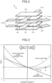
FIG. 1 is a schematic configuration diagram representing a hydrogen production system according to a first embodiment. -
FIG. 2 is a schematic diagram representing a high-temperature steam electrolysis cell. -
FIG. 3 is a graph representing a relation between current density and thermal energy. -
FIG. 4 is a schematic diagram representing a flow of steam with respect to a high-temperature steam electrolysis cell in a hydrogen production system according to a second embodiment. -
FIG. 5 is a schematic diagram representing a hydrogen ejector. -
FIG. 6 is a schematic configuration diagram representing a hydrogen production system according to a third embodiment. - The following describes preferred embodiments of the present disclosure in detail with reference to the drawings. The present disclosure is not limited to the embodiments. In a case in which there are a plurality of embodiments, a combination of the embodiments is also encompassed by the present disclosure. Constituent elements in the embodiments include a constituent element that is easily conceivable by those skilled in the art, substantially the same constituent element, and what is called an equivalent.
-
FIG. 1 is a schematic configuration diagram representing a hydrogen production system according to a first embodiment. - In the first embodiment, as illustrated in
FIG. 1 , ahydrogen production system 10 includes aheat source 11, an intermediate heat exchanger (heat exchanger) 12, a solid electrolyte type high-temperature steam electrolysis device (SOEC) 13, and aheating device 14. - The
heat source 11 is a high-temperature gas furnace, and can generate thermal energy at 900°C or higher. Theheat source 11 is not limited to the high-temperature gas furnace, and may be any heat source that can generate thermal energy at 600°C or higher. As the heat source, for example, an electric furnace, a heliostat type solar heat collecting device, a boiler and exhausted heat of the boiler, exhausted heat of a gas turbine, and the like may be applied. - The high-temperature gas furnace as the
heat source 11 is a nuclear reactor that uses a ceramics material for coating of fuel, helium for a coolant, and graphite for a moderator. The high-temperature gas furnace can generate a helium gas as a heating medium at 900°C or higher. The high-temperature gas furnace as theheat source 11 is coupled to a circulation path L11. The circulation path L11 is also coupled to anintermediate heat exchanger 21 in addition to theheat source 11. Theintermediate heat exchanger 21 is coupled to one end part of a supply path L12 and one end part of a return path L13. - The
intermediate heat exchanger 21 performs heat exchange between primary helium (a primary heating medium) flowing in the circulation path L11 and secondary helium (a secondary heating medium) flowing in the supply path L12 and the return path L13. That is, theintermediate heat exchanger 21 heats the secondary helium flowing in the supply path L12 and the return path L13 to 900°C, for example, by the primary helium at 950°C flowing in the circulation path L11, for example. - The other end part of the supply path L12 is coupled to a
supply header 22. The other end part of the return path L13 is coupled to areturn header 23. Acirculator 24 is disposed on the return path L13. Thehydrogen production system 10 produces hydrogen by using the secondary helium as a heating medium that is heated by thermal energy at 900°C or higher generated in theheat source 11. - The high-temperature
steam electrolysis device 13 produces hydrogen by water electrolysis at a high temperature of about 700°C to 900°C using a high-temperaturesteam electrolysis cell 51 as a solid electrolyte type electrolysis cell. The high-temperaturesteam electrolysis device 13 includes anelectrolyte layer 51a, a poroushydrogen electrode layer 51b, and a porousoxygen electrode layer 51c. - The high-temperature
steam electrolysis cell 51 has a flat plate shape as described later. Theelectrolyte layer 51a is an electrolyte film having a flat plate shape and constituted of a solid electrolyte of an oxygen ion conductor. The poroushydrogen electrode layer 51b is disposed on a surface on one side of theelectrolyte layer 51a, and the porousoxygen electrode layer 51c is disposed on a surface on the other side thereof. Herein, the poroushydrogen electrode layer 51b is a cathode electrode on a hydrogen side having a flat plate shape. The porousoxygen electrode layer 51c is an anode electrode on an oxygen side having a flat plate shape. - A
steam generator 31 heats water by thermal energy of the secondary helium to generate steam. Thesteam generator 31 is coupled to a water supply path L31, and also coupled to one end part of a first steam supply path L32. Theintermediate heat exchanger 12 includes afirst heat exchanger 32 and asecond heat exchanger 33. Thesecond heat exchanger 33 includes aheat exchanger 34 on the hydrogen side and aheat exchanger 35 on the oxygen side. Thefirst heat exchanger 32 is coupled to the other end part of the first steam supply path L32, and also coupled to one end part of a second steam supply path L33. The other end part of the second steam supply path L33 is coupled to asteam header 36. Thesteam header 36 is coupled to one end parts of a third steam supply path L34 and a fourth steam supply path L35. Theheat exchanger 34 on the hydrogen side is coupled to the other end part of the third steam supply path L34, and also coupled to one end part of a steam supply path L36 on the hydrogen side. Theheat exchanger 35 on the oxygen side is coupled to the other end part of the fourth steam supply path L35, and also coupled to one end part of a steam supply path L37 on the oxygen side. - The
first heat exchanger 32 superheats steam by the thermal energy of the secondary helium to generate superheated steam. Theheat exchanger 34 on the hydrogen side of thesecond heat exchanger 33 further superheats the superheated steam by the thermal energy of the secondary helium. Theheat exchanger 35 on the oxygen side of thesecond heat exchanger 33 further superheats the superheated steam by the thermal energy of the secondary helium. On the steam supply paths L32 and L33, thefirst heat exchanger 32 is disposed on an upstream side in a flowing direction of the steam, thesteam header 36 is disposed on a downstream side with respect to thefirst heat exchanger 32, and thesecond heat exchanger 33 is disposed on a downstream side with respect to thesteam header 36. Theheat exchanger 34 on the hydrogen side and theheat exchanger 35 on the oxygen side each serving as thesecond heat exchanger 33 are disposed in parallel on a downstream side of the steam supply path L33. - In the high-temperature
steam electrolysis device 13, the high-temperaturesteam electrolysis cell 51 is coupled to the other and parts of the steam supply path L36 on the hydrogen side and the steam supply path L37 on the oxygen side. The steam supply path L36 on the hydrogen side is coupled to an inlet side of the poroushydrogen electrode layer 51b, and the steam supply path L37 on the oxygen side is coupled to an inlet side of the porousoxygen electrode layer 51c. The high-temperaturesteam electrolysis device 13 is coupled to a hydrogen gas discharge path L38 and an oxygen gas discharge path L39. In the high-temperaturesteam electrolysis device 13, a hydrogen gas discharge path L38 is coupled to an outlet side of the poroushydrogen electrode layer 51b, and an oxygen gas discharge path L39 is coupled to an outlet side of the porousoxygen electrode layer 51c.Heat recovery units heat recovery units - The high-temperature
steam electrolysis device 13 is connected to a power supply path L40, and electric power (electric energy) can be supplied thereto from the outside. - The high-temperature
steam electrolysis device 13 produces hydrogen by using the steam heated by the thermal energy of the secondary helium, and also using the electric energy supplied from the power supply path L40. Theheating device 14 heats the high-temperaturesteam electrolysis cell 51 of the high-temperaturesteam electrolysis device 13 by using the steam heated by the thermal energy of the secondary helium. In this case, theheating device 14 compensates for thermal energy that is lost by endothermic reaction when the high-temperaturesteam electrolysis device 13 produces hydrogen. - The
supply header 22 is coupled to thesecond heat exchanger 33 via a heating medium supply path L14. In this case, a downstream end part of the heating medium supply path L14 branches into two parts, one of them is coupled to theheat exchanger 34 on the hydrogen side, and the other one is coupled to theheat exchanger 35 on the oxygen side. Thesecond heat exchanger 33 is coupled to thesteam generator 31 via a heating medium supply path L15. In this case, an upstream end part of the heating medium supply path L15 branches into two parts, one of them is coupled to theheat exchanger 34 on the hydrogen side, and the other one is coupled to theheat exchanger 35 on the oxygen side. Thesteam generator 31 is coupled to thereturn header 23 via a heating medium supply path L16. That is, the secondary helium in thesupply header 22 is supplied to the second heat exchanger 33 (theheat exchanger 34 on the hydrogen side, theheat exchanger 35 on the oxygen side) via the heating medium supply path L14 to superheat the steam, supplied from thesecond heat exchanger 33 to thesteam generator 31 via the heating medium supply path L15 to heat water, and returned from thesteam generator 31 to thereturn header 23 via the heating medium supply path L16. - The
supply header 22 is coupled to thefirst heat exchanger 32 via a heating medium supply path L17. Thefirst heat exchanger 32 is coupled to thereturn header 23 via the heating medium supply path L18. That is, the secondary helium in thesupply header 22 is supplied to thefirst heat exchanger 32 via the heating medium supply path L17 to superheat the steam. - The
heating device 14 is disposed as theintermediate heat exchanger 12 that heats the steam. Theheating device 14 is particularly constituted of theheat exchanger 34 on the hydrogen side and theheat exchanger 35 on the oxygen side each serving as thesecond heat exchanger 33. Theheating device 14 heats the high-temperaturesteam electrolysis cell 51 by supplying the superheated steam superheated by the second heat exchanger 33 (theheat exchanger 34 on the hydrogen side, the heat exchanger on the oxygen side) to the high-temperature steam electrolysis cell 51 (the poroushydrogen electrode layer 51b, the porousoxygen electrode layer 51c). - In the high-temperature
steam electrolysis cell 51, high-temperature superheated steam is supplied from the steam supply path L36 on the hydrogen side to the poroushydrogen electrode layer 51b. Electric power is supplied to the high-temperaturesteam electrolysis cell 51 from the power supply path L40, and voltage is applied to the poroushydrogen electrode layer 51b and the porousoxygen electrode layer 51c. When the voltage is applied, the steam is electrolyzed in the poroushydrogen electrode layer 51b, and hydrogen is generated. The generated hydrogen is discharged to the hydrogen gas discharge path L38. On the other hand, oxygen ions generated by electrolysis in the poroushydrogen electrode layer 51b pass through theelectrolyte layer 51a, oxygen is generated in the porousoxygen electrode layer 51c, and the generated oxygen is discharged to the oxygen gas discharge path L39. - In the high-temperature
steam electrolysis device 13, hydrogen and oxygen are generated based on electrolysis reaction in accordance with the following expression.
H2O → H2 + 1/2O2
-
FIG. 2 is a schematic diagram representing the high-temperature steam electrolysis cell. - As illustrated in
FIG. 1 andFIG. 2 , the high-temperaturesteam electrolysis cell 51 is a solid electrolyte type steam electrolysis device having a flat plate shape. The high-temperaturesteam electrolysis cell 51 is configured by disposing the poroushydrogen electrode layer 51b having a flat plate shape on the surface on one side of theelectrolyte layer 51a having a flat plate shape, and disposing the porousoxygen electrode layer 51c having a flat plate shape on the surface on the other side thereof. Aseparator 51d on the hydrogen side is disposed on an outer side of the poroushydrogen electrode layer 51b, and aseparator 51e on the oxygen side is disposed on an outer side of the porousoxygen electrode layer 51c. - A first flow channel L51 and a second flow channel L52 are disposed inside the high-temperature
steam electrolysis cell 51. The first flow channel L51 is disposed between theseparator 51d on the hydrogen side and the poroushydrogen electrode layer 51b, and between theelectrolyte layer 51a and the porousoxygen electrode layer 51c. The second flow channel L52 is disposed between the poroushydrogen electrode layer 51b and theelectrolyte layer 51a, and between the porousoxygen electrode layer 51c and theseparator 51e on the oxygen side. The first flow channel L51 and the second flow channel L52 intersect in directions orthogonal to each other, but may be parallel with each other. - An upstream side of the first flow channel L51 is connected to the steam supply path L36 on the hydrogen side, and a downstream side thereof is connected to the hydrogen gas discharge path L38. An upstream side of the second flow channel L52 is connected to the steam supply path L37 on the oxygen side, and a downstream side thereof is connected to the oxygen gas discharge path L39.
- Thus, the superheated steam superheated by the
heat exchanger 34 on the hydrogen side is supplied from the steam supply path L36 on the hydrogen side to the first flow channel L51, and the superheated steam superheated by theheat exchanger 35 on the oxygen side is supplied from the steam supply path L37 on the oxygen side to the second flow channel L52. Herein, theheating device 14 heats the high-temperaturesteam electrolysis cell 51 by the supplied superheated steam. The superheated steam supplied to the first flow channel L51 is electrolyzed to generate hydrogen and oxygen. The superheated steam containing hydrogen is discharged to the hydrogen gas discharge path L38. On the other hand, the steam containing oxygen is pushed out by the superheated steam supplied to the second flow channel L52, and discharged to the oxygen gas discharge path L39. - A hydrogen production method according to the present embodiment includes a step of generating thermal energy at 600°C or higher, a step of heating the steam by using secondary helium (heating medium) heated by the thermal energy, a step of heating the high-temperature
steam electrolysis device 13 by using the steam, and a step of producing hydrogen by the high-temperature steam electrolysis device by using the steam. - Specifically, as illustrated in
FIG. 1 , the high-temperature gas furnace as theheat source 11 generates primary helium at 950°C, for example. The high-temperature primary helium flows through the circulation path L11, exchanges heat with the secondary helium flowing in the return path L13 in theintermediate heat exchanger 21, and heats the secondary helium to 900°C, for example. The secondary helium subjected to heat exchange in theintermediate heat exchanger 21 flows through the supply path L12 to be supplied to thesupply header 22 at about 900°C, for example. - When the
circulator 24 is driven, the high-temperature secondary helium circulates while being heated by theintermediate heat exchanger 21. The secondary helium in thesupply header 22 is supplied to thesecond heat exchanger 33 via the heating medium supply path L14 to superheat the steam, and supplied from thesecond heat exchanger 33 to thesteam generator 31 via the heating medium supply path L15, and heat water supplied from the water supply path L31 to generate the steam. Additionally, the secondary helium in thesupply header 22 is supplied to thefirst heat exchanger 32 via the heating medium supply path L17 to superheat the steam. - The
steam generator 31 heats water supplied from the water supply path L31 to generate steam. The steam is supplied to thefirst heat exchanger 32 via the first steam supply path L32 to be superheated, and supplied to thesteam header 36 via the second steam supply path L33. The heated steam in thesteam header 36 is supplied to theheat exchanger 34 on the hydrogen side via the third steam supply path L34 to be further superheated, and supplied to the poroushydrogen electrode layer 51b of the high-temperaturesteam electrolysis cell 51 as high-temperature steam at 850 °C, for example. The heated steam in thesteam header 36 is supplied to theheat exchanger 35 on the oxygen side via the fourth steam supply path L35 to be further superheated, and supplied to the porousoxygen electrode layer 51c of the high-temperaturesteam electrolysis cell 51 as high-temperature steam at 850 °C, for example. - The high-temperature
steam electrolysis cell 51 is heated by the high-temperature steam supplied from theheat exchanger 34 on the hydrogen side and theheat exchanger 35 on the oxygen side, electrolyzes the high-temperature steam by electric power supplied from the power supply path L40, and generates hydrogen and oxygen. - That is, as illustrated in
FIG. 1 andFIG. 2 , the high-temperature steam is supplied to the first flow channel L51 of the high-temperaturesteam electrolysis cell 51 through the steam supply path L36 on the hydrogen side. At this point, electric power is supplied to the high-temperaturesteam electrolysis cell 51 from the power supply path L40, and voltage is applied to the poroushydrogen electrode layer 51b and the porousoxygen electrode layer 51c. The steam in the first flow channel L51 is then electrolyzed in the poroushydrogen electrode layer 51b to generate hydrogen, and the hydrogen flows downward in the first flow channel L51. On the other hand, oxygen ions generated by electrolysis in the poroushydrogen electrode layer 51b pass through the high-temperaturesteam electrolysis cell 51 while being diffused, and are discharged to the second flow channel L2 as oxygen. - The hydrogen that has flowed in the first flow channel L51 is discharged to the hydrogen gas discharge path L38. On the other hand, the oxygen discharged to the second flow channel L52 is discharged to the oxygen gas discharge path L39. At this point, the high-temperature steam is supplied to the second flow channel L52 of the high-temperature
steam electrolysis cell 51 through the steam supply path L37 on the oxygen side. The oxygen discharged to the second flow channel L52 is then pushed out to the oxygen gas discharge path L39 by the steam supplied to the second flow channel L52. -
FIG. 3 is a graph representing a relation between current density and thermal energy. -
FIG. 3 represents a relation between current density and thermal energy in a fuel battery (SOFC) and a high-temperature steam electrolysis device (SOEC). As illustrated inFIG. 3 , heat absorption caused by high-temperature steam electrolysis is lowered as a primary function (proportional) in accordance with increasing current density. Joule heating caused by high-temperature steam electrolysis rises as a secondary function in accordance with increasing current density. Thus, heat obtained by combining Joule heating and heat absorption is lowered in accordance with increasing current density, and rises. - In conventional hydrogen production systems, the heat source (high-temperature gas furnace) 11 as in the first embodiment is not provided, so that heat generated by Joule heating caused in the high-temperature steam electrolysis device compensates for endothermic reaction at the time of electrolyzing water. That is, conventional high-temperature steam electrolysis devices operate at an electric potential equal to or higher than a thermal neutral point A.
- On the other hand, the
hydrogen production system 10 in the first embodiment includes the heat source (high-temperature gas furnace) 11, so that thehydrogen production system 10 can compensate for endothermic reaction at the time of electrolyzing water by heating the steam and the high-temperature steam electrolysis device 13 (high-temperature steam electrolysis cell 51) using the high-temperature helium that is heated by thermal energy at 600°C or higher generated by theheat source 11. Thus, thehydrogen production system 10 in the first embodiment can operate at an electric potential of an operating point B equal to or lower than the thermal neutral point A. At the operating point B, it is possible to reduce electric energy used for electrolysis of water without converting electric energy into thermal energy (Joule heating). -
FIG. 4 is a schematic diagram representing a flow of the steam with respect to the high-temperature steam electrolysis cell in the hydrogen production system according to a second embodiment, andFIG. 5 is a schematic diagram representing a hydrogen ejector. A basic configuration of the second embodiment is the same as that of the first embodiment described above, and is described with reference toFIG. 1 . A member having the same function as that in the first embodiment described above is denoted by the same reference numeral, and detailed description thereof will not be repeated. - In the second embodiment, as illustrated in
FIG. 1 andFIG. 4 , similarly to the first embodiment, ahydrogen production system 10A (FIG. 4 ) includes theheat source 11, theintermediate heat exchanger 12, the high-temperaturesteam electrolysis device 13, and theheating device 14. Thehydrogen production system 10A in the second embodiment is obtained by changing a configuration of supplying the steam to the high-temperaturesteam electrolysis device 13 in the first embodiment. - In the high-temperature
steam electrolysis device 13, an inlet side of theheat exchanger 34 on the hydrogen side is coupled to the third steam supply path L34, and an outlet side thereof is coupled to the poroushydrogen electrode layer 51b of the high-temperaturesteam electrolysis cell 51 via the steam supply path L36 on the hydrogen side. An inlet side of theheat exchanger 35 on the oxygen side is coupled to the fourth steam supply path L35, and an outlet side thereof is coupled to the porousoxygen electrode layer 51c of the high-temperaturesteam electrolysis cell 51 via the steam supply path L37 on the oxygen side. In the high-temperaturesteam electrolysis cell 51, the poroushydrogen electrode layer 51b is coupled to the hydrogen gas discharge path L38, and the porousoxygen electrode layer 51c is coupled to the oxygen gas discharge path L39. - As illustrated in
FIG. 4 , a circulation path L61 on the hydrogen side and a circulation path L62 on the oxygen side are disposed in thehydrogen production system 10A. One end part of the circulation path L61 on the hydrogen side is coupled to abranch part 61 of the hydrogen gas discharge path L38, and the other end part thereof is coupled to the third steam supply path L34. Anejector 62 on the hydrogen side is disposed at a coupling part between the circulation path L61 on the hydrogen side and the third steam supply path L34. One end part of the circulation path L62 on the oxygen side is coupled to abranch part 63 of the oxygen gas discharge path L39, and the other end part thereof is coupled to the fourth steam supply path L35. Anejector 64 on the oxygen side is disposed at a coupling part between the circulation path L62 on the oxygen side and the fourth steam supply path L35. - The
ejector 62 on the hydrogen side and theejector 64 on the oxygen side have similar configurations. As illustrated inFIG. 4 and FIG. 5 , theejector 62 on the hydrogen side includes amain body 71, a nozzle 72, and adiffuser 73. Themain body 71 has a cylindrical shape, and includes aninlet part 71a disposed on a base end part and asuction part 71b disposed on an outer peripheral part. Thesuction part 71b is coupled to the circulation path L61 on the hydrogen side. The nozzle 72 is coupled to themain body 71 to communicate with theinlet part 71a. The nozzle 72 has a cylindrical shape, and a flow channel thereof is narrowed toward the downstream side. Thediffuser 73 is coupled to themain body 71 to communicate with the nozzle 72. Thediffuser 73 has a cylindrical shape, and a flow channel thereof is widened toward the downstream side. Anejection part 73a is disposed on a front end portion of thediffuser 73. - Thus, the steam in the third steam supply path L34 passes through the
ejector 62 on the hydrogen side to be supplied to theheat exchanger 34 on the hydrogen side, is superheated therein to be superheated steam, and is supplied to the poroushydrogen electrode layer 51b of the high-temperaturesteam electrolysis cell 51. The steam containing hydrogen generated in the high-temperaturesteam electrolysis cell 51 is discharged to the hydrogen gas discharge path L38. - At this point, the steam containing hydrogen discharged to the hydrogen gas discharge path L38 partially flows to the circulation path L61 on the hydrogen side. In the
ejector 62 on the hydrogen side, flow velocity of the steam supplied from theinlet part 71a is increased at the nozzle 72, so that suction force works on thesuction part 71b. The steam containing hydrogen that has flowed from the hydrogen gas discharge path L38 to the circulation path L61 on the hydrogen side is sucked into themain body 71 via thesuction part 71b. The steam containing hydrogen that has been sucked into themain body 71 through thesuction part 71b from the circulation path L61 on the hydrogen side is mixed with the steam supplied from theinlet part 71a, and supplied to the poroushydrogen electrode layer 51b. - On the other hand, the steam in the fourth steam supply path L35 passes through the
ejector 64 on the oxygen side to be supplied to theheat exchanger 35 on the oxygen side, is superheated therein to be superheated steam, and is supplied to the porousoxygen electrode layer 51c of the high-temperaturesteam electrolysis cell 51. The steam containing oxygen generated in the high-temperaturesteam electrolysis cell 51 is discharged to the oxygen gas discharge path L39. - At this point, the steam containing oxygen discharged to the oxygen gas discharge path L39 partially flows to the circulation path L62 on the oxygen side. In the
ejector 64 on the oxygen side, similarly to theejector 62 on the hydrogen side, the steam containing oxygen that has flowed from the oxygen gas discharge path L39 to the circulation path L62 on the oxygen side is sucked, mixed with the supplied steam, and supplied to the porousoxygen electrode layer 51c. - In the
hydrogen production system 10A, part of the steam containing hydrogen discharged from the poroushydrogen electrode layer 51b of the high-temperaturesteam electrolysis cell 51 is returned to the inlet side of the poroushydrogen electrode layer 51b via the circulation path L61 on the hydrogen side. Thus, the superheated steam the amount of which is larger than a required amount for steam electrolysis can be supplied to the poroushydrogen electrode layer 51b, and endothermic reaction of steam electrolysis can be compensated for. In thehydrogen production system 10A, part of the steam containing oxygen discharged from the porousoxygen electrode layer 51c of the high-temperaturesteam electrolysis cell 51 is returned to the inlet side of the porousoxygen electrode layer 51c via the circulation path L62 on the oxygen side. Thus, a large amount of superheated steam can be supplied to the porousoxygen electrode layer 51c, and it is possible to prevent the temperature of the high-temperaturesteam electrolysis cell 51 from being lowered due to the endothermic reaction. -
FIG. 6 is a schematic configuration diagram representing the hydrogen production system according to a third embodiment. A member having the same function as that in the first embodiment described above is denoted by the same reference numeral, and detailed description thereof will not be repeated. - In the third embodiment, as illustrated in
FIG. 6 , similarly to the first embodiment, ahydrogen production system 10B includes theheat source 11, theintermediate heat exchanger 12, the high-temperaturesteam electrolysis device 13, and theheating device 14. Thehydrogen production system 10B in the third embodiment is obtained by changing a configuration of supplying gas to the high-temperaturesteam electrolysis device 13 in the first embodiment. - The
supply header 22 is coupled to thesecond heat exchanger 33 via the heating medium supply path L14. Thesecond heat exchanger 33 is coupled to thefirst heat exchanger 32 via a heating medium supply path L19. That is, the secondary helium in thesupply header 22 is supplied to thesecond heat exchanger 33 via the heating medium supply path L14 to superheat the steam, and supplied from thesecond heat exchanger 33 to thefirst heat exchanger 32 to heat the steam. Thefirst heat exchanger 32 is coupled to thereturn header 23 via the heating medium supply path L18. - A
gas supply device 41 supplies gas (air or steam) to the porousoxygen electrode layer 51c of the high-temperaturesteam electrolysis cell 51. Agas heating device 42 heats the gas supplied to the porousoxygen electrode layer 51c by the thermal energy of the secondary helium. Acirculator 43 constituting thegas supply device 41 is disposed on a gas supply path L41. The gas supply path L41 is coupled to theheat recovery unit 38. Theheat recovery unit 38 is coupled to thegas heating device 42 via a gas supply path L42. Thegas heating device 42 is coupled to the porousoxygen electrode layer 51c via a gas supply path L43. - The
supply header 22 is coupled to thegas heating device 42 via a heating medium supply path L20. Thegas heating device 42 is coupled to thesteam generator 31 via a heating medium supply path L21. That is, the secondary helium in thesupply header 22 is supplied to thegas heating device 42 via the heating medium supply path L20 to heat gas, and supplied from thegas heating device 42 to thesteam generator 31 via the heating medium supply path L21. - When the
circulator 43 is driven, the gas (air) is supplied from the gas supply path L41 to theheat recovery unit 38, and heated by oxygen flowing in the oxygen gas discharge path L39. The heated gas is supplied to thegas heating device 42 via the gas supply path L42, and heated by the thermal energy of the secondary helium. The heated gas is supplied to the porousoxygen electrode layer 51c via the gas supply path L43, and generated oxygen is discharged to the oxygen gas discharge path L39. - The
hydrogen production system 10B uses gas heated by the thermal energy of the secondary helium as a carrier gas for discharging the oxygen generated by the high-temperaturesteam electrolysis device 13 to the oxygen gas discharge path L39. Thus, the oxygen generated by the high-temperaturesteam electrolysis device 13 can be efficiently discharged without lowering the temperature of the high-temperaturesteam electrolysis device 13. - The hydrogen production system according to a first aspect includes the
intermediate heat exchanger 12 that heats the steam by using the secondary helium (heating medium) heated by thermal energy at 600°C or higher, the high-temperaturesteam electrolysis device 13 that produces hydrogen by using the steam, and theheating device 14 that heats the high-temperaturesteam electrolysis device 13 by using the steam. - The hydrogen production system according to the first aspect heats the high-temperature
steam electrolysis device 13 by high-temperature steam heated by using the heating medium heated by the thermal energy at 600°C or higher, and supplies the high-temperature steam heated by using the heating medium heated by the thermal energy at 600°C or higher to the high-temperaturesteam electrolysis device 13 to produce hydrogen by electrolysis. Thus, it is possible to suppress generation of carbon dioxide by reducing a use amount of electric energy generated by a thermal power generation system and the like, and energy cost can be reduced. - In the hydrogen production system according to a second aspect, the
heating device 14 compensates for thermal energy that is lost by endothermic reaction when the high-temperaturesteam electrolysis device 13 produces hydrogen. Due to this, it is possible to reduce a supply amount of thermal energy from the outside to the high-temperaturesteam electrolysis device 13. - In the hydrogen production system according to a third aspect, the
electrolyte layer 51a having a flat plate shape, the poroushydrogen electrode layer 51b having a flat plate shape that is disposed on one surface side of theelectrolyte layer 51a, and the porousoxygen electrode layer 51c having a flat plate shape that is disposed on the other surface side of theelectrolyte layer 51a are disposed as the high-temperaturesteam electrolysis cell 51, and the steam is supplied to the poroushydrogen electrode layer 51b. Due to this, the high-temperaturesteam electrolysis device 13 can be heated by the high-temperature steam that is electrolyzed by the high-temperaturesteam electrolysis device 13 to produce hydrogen, and the structure of the high-temperaturesteam electrolysis cell 51 can be simplified. - In the hydrogen production system according to a fourth aspect, the circulation path L61 on the hydrogen side is disposed to return part of the steam containing hydrogen discharged from a discharge side of the porous
hydrogen electrode layer 51b to the inlet side of the poroushydrogen electrode layer 51b. Due to this, the superheated steam the amount of which is larger than a required amount for steam electrolysis can be supplied to the poroushydrogen electrode layer 51b, and endothermic reaction of steam electrolysis can be compensated for. - In the hydrogen production system according to a fifth aspect, the circulation path L62 on the oxygen side is disposed to return part of the steam containing oxygen discharged from a discharge side of the porous
oxygen electrode layer 51c to the inlet side of the porousoxygen electrode layer 51c. Due to this, a large amount of superheated steam can be supplied to the porousoxygen electrode layer 51c, and it is possible to prevent the temperature of the high-temperaturesteam electrolysis cell 51 from being lowered due to the endothermic reaction. - The hydrogen production system according to a sixth aspect includes the
steam generator 31 that generates the steam to be supplied to the high-temperaturesteam electrolysis device 13 via the steam supply paths L32, L33, L34, and L35. Theintermediate heat exchanger 12 includes thefirst heat exchanger 32 disposed on the steam supply paths L32 and L33, and thesecond heat exchanger 33 disposed on the downstream side with respect to thefirst heat exchanger 32 on the steam supply paths L33, L34, and L35. The secondary helium is supplied from thesecond heat exchanger 33 to thefirst heat exchanger 32. Due to this, by supplying the heating medium from thesecond heat exchanger 33 on the downstream side to thefirst heat exchanger 32 on the upstream side, the thermal energy of the heating medium can be effectively used. - The hydrogen production system according to a seventh aspect includes the
heat exchanger 34 on the hydrogen side that heats the steam to be supplied to the poroushydrogen electrode layer 51b, and theheat exchanger 35 on the oxygen side that heats the steam to be supplied to the porousoxygen electrode layer 51c as thesecond heat exchanger 33. Due to this, the steam to be supplied to the poroushydrogen electrode layer 51b and the steam to be supplied to theheat exchanger 35 on the oxygen side can be efficiently heated. - The hydrogen production system according to an eighth aspect includes the
gas supply device 41 that supplies gas to the porousoxygen electrode layer 51c, and thegas heating device 42 that heats gas to be supplied to the porousoxygen electrode layer 51c using the secondary helium. Due to this, the oxygen generated by the high-temperaturesteam electrolysis cell 51 can be efficiently discharged without lowering the temperature of the high-temperaturesteam electrolysis cell 51. - In the hydrogen production system according to a ninth aspect, the high-temperature gas furnace is disposed as the
heat source 11 that can generate thermal energy, and theintermediate heat exchanger 12 heats the steam by using the heating medium that is heated by the thermal energy of high-temperature helium generated in the high-temperature gas furnace. Due to this, a generation amount of carbon dioxide can be reduced. - The hydrogen production method according to a tenth aspect includes a step of generating thermal energy at 600°C or higher, a step of heating the steam by using secondary helium (heating medium) heated by the thermal energy, a step of heating the high-temperature
steam electrolysis device 13 by using the steam, and a step of producing hydrogen by the high-temperature steam electrolysis device by using the steam. Due to this, it is possible to suppress generation of carbon dioxide by reducing a use amount of electric energy generated by a thermal power generation system and the like, and energy cost can be reduced. - In the embodiments described above, the high-temperature
steam electrolysis cell 51 is assumed to have a flat plate shape, but the shape is not limited thereto. -
- 10, 10A, 10B
- HYDROGEN PRODUCTION SYSTEM
- 11
- HEAT SOURCE
- 12
- INTERMEDIATE HEAT EXCHANGER (HEAT EXCHANGER)
- 13
- HIGH-TEMPERATURE STEAM ELECTROLYSIS DEVICE
- 14
- HEATING DEVICE
- 21
- INTERMEDIATE HEAT EXCHANGER (HEAT EXCHANGER)
- 22
- SUPPLY HEADER
- 23
- RETURN HEADER
- 24
- CIRCULATOR
- 31
- STEAM GENERATOR
- 32
- FIRST HEAT EXCHANGER
- 33
- SECOND HEAT EXCHANGER
- 34
- HEAT EXCHANGER ON HYDROGEN SIDE
- 35
- HEAT EXCHANGER ON OXYGEN SIDE
- 36
- STEAM HEADER
- 37,
- 38 HEAT RECOVERY UNIT
- 41
- GAS SUPPLY DEVICE
- 42
- GAS HEATING DEVICE
- 43
- CIRCULATOR
- 51
- HIGH-TEMPERATURE STEAM ELECTROLYSIS CELL
- 51a
- ELECTROLYTE LAYER
- 51b
- POROUS HYDROGEN ELECTRODE LAYER
- 51c
- POROUS OXYGEN ELECTRODE LAYER
- 51d
- SEPARATOR ON HYDROGEN SIDE
- 51e
- SEPARATOR ON OXYGEN SIDE
- 61
- BRANCH PART
- 62
- EJECTOR ON HYDROGEN SIDE
- 63
- BRANCH PART
- 64
- EJECTOR ON OXYGEN SIDE
- L11
- CIRCULATION PATH
- L12
- SUPPLY PATH
- L13
- RETURN PATH
- L14, L15, L16, L17, L18, L19, L20, L21
- HEATING MEDIUM SUPPLY PATH
- L31
- WATER SUPPLY PATH
- L32
- FIRST STEAM SUPPLY PATH
- L33
- SECOND STEAM SUPPLY PATH
- L34
- THIRD STEAM SUPPLY PATH
- L35
- FOURTH STEAM SUPPLY PATH
- L36
- STEAM SUPPLY PATH ON HYDROGEN SIDE
- L37
- STEAM SUPPLY PATH ON OXYGEN SIDE
- L38
- HYDROGEN GAS DISCHARGE PATH
- L39
- OXYGEN GAS DISCHARGE PATH
- L40
- POWER SUPPLY PATH
- L41, L42, L43
- GAS SUPPLY PATH
- L51
- FIRST FLOW CHANNEL
- L52
- SECOND FLOW CHANNEL
- L61
- CIRCULATION PATH ON HYDROGEN SIDE
- L62
- CIRCULATION PATH ON OXYGEN SIDE
Claims (10)
- A hydrogen production system comprising:a heat exchanger that heats steam by using a heating medium heated by thermal energy at 600°C or higher;a high-temperature steam electrolysis device that produces hydrogen by using the steam; anda heating device that heats the high-temperature steam electrolysis device by using the steam.
- The hydrogen production system according to claim 1, wherein the heating device compensates for thermal energy that is lost by endothermic reaction when the high-temperature steam electrolysis device produces hydrogen.
- The hydrogen production system according to claim 1 or 2, wherein the high-temperature steam electrolysis device includes an electrolyte layer having a flat plate shape, a hydrogen electrode layer having a flat plate shape that is disposed on one surface side of the electrolyte layer, and an oxygen electrode layer having a flat plate shape that is disposed on the other surface side of the electrolyte layer, and the steam is supplied to the hydrogen electrode layer.
- The hydrogen production system according to claim 3, wherein a circulation path on a hydrogen side is disposed to return part of steam containing hydrogen discharged from a discharge side of the hydrogen electrode layer to an inlet side of the hydrogen electrode layer.
- The hydrogen production system according to claim 3, wherein a circulation path on an oxygen side is disposed to return part of steam containing oxygen discharged from a discharge side of the oxygen electrode layer to an inlet side of the oxygen electrode layer.
- The hydrogen production system according to claim 3, comprising a steam generator that generates the steam to be supplied to the high-temperature steam electrolysis device via a steam supply path,wherein the heat exchanger includes a first heat exchanger disposed on the steam supply path and a second heat exchanger disposed on a downstream side with respect to the first heat exchanger on the steam supply path, andthe heating medium is supplied from the second heat exchanger to the first heat exchanger.
- The hydrogen production system according to claim 6, wherein the second heat exchanger includes a heat exchanger on a hydrogen side that heats the steam to be supplied to the hydrogen electrode layer, and a heat exchanger on an oxygen side that heats the steam to be supplied to the oxygen electrode layer.
- The hydrogen production system according to claim 3, comprising:a gas supply device that supplies gas to the oxygen electrode layer; anda gas heating device that heats the gas by using the heating medium.
- The hydrogen production system according to claim 1, whereina high-temperature gas furnace is disposed as a heat source for generating the thermal energy, andthe heat exchanger heats steam by using a heating medium heated by thermal energy of high-temperature helium generated in the high-temperature gas furnace.
- A hydrogen production method comprising the steps of:generating thermal energy at 600°C or higher;heating steam by using a heating medium heated by the thermal energy;heating a high-temperature steam electrolysis device by using the steam; andproducing hydrogen by the high-temperature steam electrolysis device by using the steam.
Applications Claiming Priority (2)
| Application Number | Priority Date | Filing Date | Title |
|---|---|---|---|
| JP2021161626A JP7374155B2 (en) | 2021-09-30 | 2021-09-30 | Hydrogen production system and hydrogen production method |
| PCT/JP2022/017840 WO2023053546A1 (en) | 2021-09-30 | 2022-04-14 | Hydrogen production system and hydrogen production method |
Publications (2)
| Publication Number | Publication Date |
|---|---|
| EP4394087A1 true EP4394087A1 (en) | 2024-07-03 |
| EP4394087A4 EP4394087A4 (en) | 2025-07-09 |
Family
ID=85782214
Family Applications (1)
| Application Number | Title | Priority Date | Filing Date |
|---|---|---|---|
| EP22875429.7A Pending EP4394087A4 (en) | 2021-09-30 | 2022-04-14 | Hydrogen production system and hydrogen production process |
Country Status (6)
| Country | Link |
|---|---|
| US (1) | US20240376611A1 (en) |
| EP (1) | EP4394087A4 (en) |
| JP (1) | JP7374155B2 (en) |
| KR (1) | KR20240042564A (en) |
| CN (1) | CN118103552A (en) |
| WO (1) | WO2023053546A1 (en) |
Families Citing this family (1)
| Publication number | Priority date | Publication date | Assignee | Title |
|---|---|---|---|---|
| WO2026009969A1 (en) * | 2024-07-05 | 2026-01-08 | 国立大学法人東京科学大学 | Hydrogen production apparatus and hydrogen production method |
Family Cites Families (15)
| Publication number | Priority date | Publication date | Assignee | Title |
|---|---|---|---|---|
| JPH04320999A (en) * | 1991-04-19 | 1992-11-11 | Ishikawajima Harima Heavy Ind Co Ltd | Hydrogen gas producing device using high temperature gas reactor |
| JP2002047591A (en) | 2000-07-28 | 2002-02-15 | Japan Atom Energy Res Inst | Electrochemical reactor |
| JP2006307290A (en) | 2005-04-28 | 2006-11-09 | Hitachi Ltd | Hydrogen production method |
| JP5005896B2 (en) * | 2005-07-27 | 2012-08-22 | 株式会社東芝 | Steam electrolysis method and steam electrolysis apparatus |
| JP5005898B2 (en) * | 2005-08-31 | 2012-08-22 | 株式会社東芝 | Steam electrolysis apparatus and method |
| US7436922B2 (en) | 2005-12-21 | 2008-10-14 | General Electric Company | Electricity and steam generation from a helium-cooled nuclear reactor |
| JP2009001878A (en) | 2007-06-22 | 2009-01-08 | Toshiba Corp | High temperature steam electrolysis method and apparatus |
| FR2919617B1 (en) * | 2007-08-02 | 2009-11-20 | Commissariat Energie Atomique | HIGH TEMPERATURE AND HIGH PRESSURE ELECTROLYSIS WITH ALLOTHERMIC OPERATION |
| US8132410B2 (en) | 2007-12-17 | 2012-03-13 | Battelle Energy Alliance, Llc | Methods and systems for the production of hydrogen |
| JP2010090425A (en) | 2008-10-07 | 2010-04-22 | Toshiba Corp | Hydrogen producing apparatus and method thereof |
| JP2010176939A (en) * | 2009-01-28 | 2010-08-12 | Toshiba Corp | Power storage system, and operation method thereof |
| FR2957361B1 (en) | 2010-03-12 | 2012-04-20 | Commissariat Energie Atomique | HIGH TEMPERATURE (EHT) ELECTROLYSIS WITH ENHANCED OPERATING SAFETY |
| CN107431219A (en) | 2015-04-08 | 2017-12-01 | 太阳火有限公司 | Thermal management methods for high temperature steam electrolysis [SOEC], solid oxide fuel cells [SOFC] and/or reversible high temperature fuel cells [rSOC] and high temperature steam electrolysis [SOEC], solid oxide fuel cells [SOFC] and/or or reversible high-temperature fuel cell [rSOC] devices |
| JP7110042B2 (en) | 2018-09-13 | 2022-08-01 | 東芝エネルギーシステムズ株式会社 | Hydrogen production device and hydrogen production method |
| EP3766831A1 (en) * | 2019-07-18 | 2021-01-20 | Linde GmbH | Method for operating a fired furnace and arrangement comprising such a furnace |
-
2021
- 2021-09-30 JP JP2021161626A patent/JP7374155B2/en active Active
-
2022
- 2022-04-14 KR KR1020247009884A patent/KR20240042564A/en active Pending
- 2022-04-14 EP EP22875429.7A patent/EP4394087A4/en active Pending
- 2022-04-14 US US18/691,115 patent/US20240376611A1/en active Pending
- 2022-04-14 CN CN202280065817.XA patent/CN118103552A/en active Pending
- 2022-04-14 WO PCT/JP2022/017840 patent/WO2023053546A1/en not_active Ceased
Also Published As
| Publication number | Publication date |
|---|---|
| EP4394087A4 (en) | 2025-07-09 |
| US20240376611A1 (en) | 2024-11-14 |
| KR20240042564A (en) | 2024-04-02 |
| WO2023053546A1 (en) | 2023-04-06 |
| JP7374155B2 (en) | 2023-11-06 |
| CN118103552A (en) | 2024-05-28 |
| JP2023051135A (en) | 2023-04-11 |
Similar Documents
| Publication | Publication Date | Title |
|---|---|---|
| Aulakh et al. | On the reduction of electric energy consumption in electrolysis: A thermodynamic study | |
| EP4512932A1 (en) | Hydrogen production system and hydrogen production method | |
| CN114725428A (en) | Zero-carbon-emission solid oxide fuel cell and renewable energy source combined power generation system with ammonia gas as carrier | |
| JP7374152B2 (en) | Hydrogen production system and hydrogen production method | |
| JP2006307290A (en) | Hydrogen production method | |
| EP4342843A1 (en) | Hydrogen production system and hydrogen production method | |
| EP4365128A1 (en) | High-temperature steam electrolysis device, hydrogen production method, and hydrogen production system | |
| JP7374155B2 (en) | Hydrogen production system and hydrogen production method | |
| JPH04115470A (en) | Power storage generator | |
| CN115732730B (en) | A reversible solid oxide battery system and hydrogen and oxygen preparation method | |
| JP7565850B2 (en) | Hydrogen production system and hydrogen production method | |
| CN118289865B (en) | Multi-energy coupling hydrogen production-sea water desalination system utilizing liquid metal magnetofluid power generation | |
| JP2001332271A (en) | Storage generator | |
| Shang et al. | Exergetic performance analysis of a direct ammonia-fed solid oxide fuel cell | |
| JP2026505263A (en) | Electrolyzer systems for intermittent electricity supply | |
| PETIPAS et al. | Control of a high-temperature electrolyzer | |
| Fillo et al. | Fusion energy for hydrogen production |
Legal Events
| Date | Code | Title | Description |
|---|---|---|---|
| STAA | Information on the status of an ep patent application or granted ep patent |
Free format text: STATUS: THE INTERNATIONAL PUBLICATION HAS BEEN MADE |
|
| PUAI | Public reference made under article 153(3) epc to a published international application that has entered the european phase |
Free format text: ORIGINAL CODE: 0009012 |
|
| STAA | Information on the status of an ep patent application or granted ep patent |
Free format text: STATUS: REQUEST FOR EXAMINATION WAS MADE |
|
| 17P | Request for examination filed |
Effective date: 20240327 |
|
| AK | Designated contracting states |
Kind code of ref document: A1 Designated state(s): AL AT BE BG CH CY CZ DE DK EE ES FI FR GB GR HR HU IE IS IT LI LT LU LV MC MK MT NL NO PL PT RO RS SE SI SK SM TR |
|
| DAV | Request for validation of the european patent (deleted) | ||
| DAX | Request for extension of the european patent (deleted) | ||
| A4 | Supplementary search report drawn up and despatched |
Effective date: 20250606 |
|
| RIC1 | Information provided on ipc code assigned before grant |
Ipc: C25B 15/08 20060101ALI20250602BHEP Ipc: C25B 11/02 20210101ALI20250602BHEP Ipc: C25B 1/042 20210101ALI20250602BHEP Ipc: C25B 15/021 20210101ALI20250602BHEP Ipc: C25B 15/027 20210101ALI20250602BHEP Ipc: C25B 9/67 20210101ALI20250602BHEP Ipc: C25B 9/23 20210101ALI20250602BHEP Ipc: C25B 9/00 20210101AFI20250602BHEP |