EP4394082A1 - Superalloy components having coatings thereon and methods for producing the same - Google Patents
Superalloy components having coatings thereon and methods for producing the same Download PDFInfo
- Publication number
- EP4394082A1 EP4394082A1 EP23214207.5A EP23214207A EP4394082A1 EP 4394082 A1 EP4394082 A1 EP 4394082A1 EP 23214207 A EP23214207 A EP 23214207A EP 4394082 A1 EP4394082 A1 EP 4394082A1
- Authority
- EP
- European Patent Office
- Prior art keywords
- substrate
- oxide
- coating
- component
- heat treatment
- Prior art date
- Legal status (The legal status is an assumption and is not a legal conclusion. Google has not performed a legal analysis and makes no representation as to the accuracy of the status listed.)
- Pending
Links
- 238000000576 coating method Methods 0.000 title claims abstract description 59
- 238000000034 method Methods 0.000 title claims abstract description 57
- 229910000601 superalloy Inorganic materials 0.000 title claims abstract description 25
- 239000000758 substrate Substances 0.000 claims abstract description 116
- 239000011248 coating agent Substances 0.000 claims abstract description 57
- 238000010438 heat treatment Methods 0.000 claims abstract description 41
- 239000002002 slurry Substances 0.000 claims abstract description 32
- 239000002244 precipitate Substances 0.000 claims abstract description 24
- PXHVJJICTQNCMI-UHFFFAOYSA-N Nickel Chemical compound [Ni] PXHVJJICTQNCMI-UHFFFAOYSA-N 0.000 claims abstract description 22
- 229910052759 nickel Inorganic materials 0.000 claims abstract description 11
- 238000009826 distribution Methods 0.000 claims abstract description 6
- 238000001035 drying Methods 0.000 claims abstract description 5
- 150000003839 salts Chemical class 0.000 claims description 15
- RAHZWNYVWXNFOC-UHFFFAOYSA-N Sulphur dioxide Chemical class O=S=O RAHZWNYVWXNFOC-UHFFFAOYSA-N 0.000 claims description 10
- 239000007789 gas Substances 0.000 claims description 9
- 238000004519 manufacturing process Methods 0.000 claims description 8
- 230000007797 corrosion Effects 0.000 claims description 7
- 238000005260 corrosion Methods 0.000 claims description 7
- QVQLCTNNEUAWMS-UHFFFAOYSA-N barium oxide Chemical compound [Ba]=O QVQLCTNNEUAWMS-UHFFFAOYSA-N 0.000 claims description 6
- 230000007547 defect Effects 0.000 claims description 6
- IATRAKWUXMZMIY-UHFFFAOYSA-N strontium oxide Chemical compound [O-2].[Sr+2] IATRAKWUXMZMIY-UHFFFAOYSA-N 0.000 claims description 6
- DGAQECJNVWCQMB-PUAWFVPOSA-M Ilexoside XXIX Chemical class C[C@@H]1CC[C@@]2(CC[C@@]3(C(=CC[C@H]4[C@]3(CC[C@@H]5[C@@]4(CC[C@@H](C5(C)C)OS(=O)(=O)[O-])C)C)[C@@H]2[C@]1(C)O)C)C(=O)O[C@H]6[C@@H]([C@H]([C@@H]([C@H](O6)CO)O)O)O.[Na+] DGAQECJNVWCQMB-PUAWFVPOSA-M 0.000 claims description 5
- FYYHWMGAXLPEAU-UHFFFAOYSA-N Magnesium Chemical class [Mg] FYYHWMGAXLPEAU-UHFFFAOYSA-N 0.000 claims description 5
- 230000008021 deposition Effects 0.000 claims description 5
- 229910052749 magnesium Inorganic materials 0.000 claims description 5
- 239000011777 magnesium Chemical class 0.000 claims description 5
- 238000002844 melting Methods 0.000 claims description 5
- 230000008018 melting Effects 0.000 claims description 5
- 239000000203 mixture Substances 0.000 claims description 5
- 229910052708 sodium Inorganic materials 0.000 claims description 5
- 239000011734 sodium Substances 0.000 claims description 5
- 229910052720 vanadium Inorganic materials 0.000 claims description 5
- LEONUFNNVUYDNQ-UHFFFAOYSA-N vanadium atom Chemical class [V] LEONUFNNVUYDNQ-UHFFFAOYSA-N 0.000 claims description 5
- 230000000694 effects Effects 0.000 claims description 4
- 239000011521 glass Substances 0.000 claims description 4
- VYPSYNLAJGMNEJ-UHFFFAOYSA-N Silicium dioxide Chemical compound O=[Si]=O VYPSYNLAJGMNEJ-UHFFFAOYSA-N 0.000 claims description 3
- GWEVSGVZZGPLCZ-UHFFFAOYSA-N Titan oxide Chemical compound O=[Ti]=O GWEVSGVZZGPLCZ-UHFFFAOYSA-N 0.000 claims description 3
- BRPQOXSCLDDYGP-UHFFFAOYSA-N calcium oxide Chemical compound [O-2].[Ca+2] BRPQOXSCLDDYGP-UHFFFAOYSA-N 0.000 claims description 3
- ODINCKMPIJJUCX-UHFFFAOYSA-N calcium oxide Inorganic materials [Ca]=O ODINCKMPIJJUCX-UHFFFAOYSA-N 0.000 claims description 3
- 239000000292 calcium oxide Substances 0.000 claims description 3
- 229910000428 cobalt oxide Inorganic materials 0.000 claims description 3
- IVMYJDGYRUAWML-UHFFFAOYSA-N cobalt(ii) oxide Chemical compound [Co]=O IVMYJDGYRUAWML-UHFFFAOYSA-N 0.000 claims description 3
- CPLXHLVBOLITMK-UHFFFAOYSA-N magnesium oxide Inorganic materials [Mg]=O CPLXHLVBOLITMK-UHFFFAOYSA-N 0.000 claims description 3
- 239000000395 magnesium oxide Substances 0.000 claims description 3
- AXZKOIWUVFPNLO-UHFFFAOYSA-N magnesium;oxygen(2-) Chemical compound [O-2].[Mg+2] AXZKOIWUVFPNLO-UHFFFAOYSA-N 0.000 claims description 3
- 229910044991 metal oxide Inorganic materials 0.000 claims description 3
- 150000004706 metal oxides Chemical class 0.000 claims description 3
- TWNQGVIAIRXVLR-UHFFFAOYSA-N oxo(oxoalumanyloxy)alumane Chemical compound O=[Al]O[Al]=O TWNQGVIAIRXVLR-UHFFFAOYSA-N 0.000 claims description 3
- 229910052814 silicon oxide Inorganic materials 0.000 claims description 3
- OGIDPMRJRNCKJF-UHFFFAOYSA-N titanium oxide Inorganic materials [Ti]=O OGIDPMRJRNCKJF-UHFFFAOYSA-N 0.000 claims description 3
- 230000007704 transition Effects 0.000 claims description 3
- QVGXLLKOCUKJST-UHFFFAOYSA-N atomic oxygen Chemical compound [O] QVGXLLKOCUKJST-UHFFFAOYSA-N 0.000 claims description 2
- 239000001301 oxygen Substances 0.000 claims description 2
- 229910052760 oxygen Inorganic materials 0.000 claims description 2
- 230000006641 stabilisation Effects 0.000 claims description 2
- 238000011105 stabilization Methods 0.000 claims description 2
- UQSXHKLRYXJYBZ-UHFFFAOYSA-N Iron oxide Chemical compound [Fe]=O UQSXHKLRYXJYBZ-UHFFFAOYSA-N 0.000 claims 4
- 229910052810 boron oxide Inorganic materials 0.000 claims 2
- JKWMSGQKBLHBQQ-UHFFFAOYSA-N diboron trioxide Chemical compound O=BOB=O JKWMSGQKBLHBQQ-UHFFFAOYSA-N 0.000 claims 2
- 229910000480 nickel oxide Inorganic materials 0.000 claims 2
- GNRSAWUEBMWBQH-UHFFFAOYSA-N oxonickel Chemical compound [Ni]=O GNRSAWUEBMWBQH-UHFFFAOYSA-N 0.000 claims 2
- RVTZCBVAJQQJTK-UHFFFAOYSA-N oxygen(2-);zirconium(4+) Chemical compound [O-2].[O-2].[Zr+4] RVTZCBVAJQQJTK-UHFFFAOYSA-N 0.000 claims 2
- 229910001928 zirconium oxide Inorganic materials 0.000 claims 2
- 230000008569 process Effects 0.000 description 13
- 230000035882 stress Effects 0.000 description 10
- 230000009977 dual effect Effects 0.000 description 7
- 230000032683 aging Effects 0.000 description 5
- 230000006698 induction Effects 0.000 description 4
- 239000000463 material Substances 0.000 description 4
- 238000011282 treatment Methods 0.000 description 4
- 230000009471 action Effects 0.000 description 3
- 230000015572 biosynthetic process Effects 0.000 description 3
- XKRFYHLGVUSROY-UHFFFAOYSA-N Argon Chemical compound [Ar] XKRFYHLGVUSROY-UHFFFAOYSA-N 0.000 description 2
- 229910045601 alloy Inorganic materials 0.000 description 2
- 239000000956 alloy Substances 0.000 description 2
- 239000011230 binding agent Substances 0.000 description 2
- 230000007613 environmental effect Effects 0.000 description 2
- 229910000856 hastalloy Inorganic materials 0.000 description 2
- XEEYBQQBJWHFJM-UHFFFAOYSA-N iron Substances [Fe] XEEYBQQBJWHFJM-UHFFFAOYSA-N 0.000 description 2
- 238000004881 precipitation hardening Methods 0.000 description 2
- 229910019589 Cr—Fe Inorganic materials 0.000 description 1
- UFHFLCQGNIYNRP-UHFFFAOYSA-N Hydrogen Chemical compound [H][H] UFHFLCQGNIYNRP-UHFFFAOYSA-N 0.000 description 1
- WAIPAZQMEIHHTJ-UHFFFAOYSA-N [Cr].[Co] Chemical compound [Cr].[Co] WAIPAZQMEIHHTJ-UHFFFAOYSA-N 0.000 description 1
- 238000005299 abrasion Methods 0.000 description 1
- 238000003483 aging Methods 0.000 description 1
- 229910052786 argon Inorganic materials 0.000 description 1
- -1 but not limited to Chemical class 0.000 description 1
- 238000005266 casting Methods 0.000 description 1
- 239000010941 cobalt Substances 0.000 description 1
- 229910017052 cobalt Inorganic materials 0.000 description 1
- GUTLYIVDDKVIGB-UHFFFAOYSA-N cobalt atom Chemical compound [Co] GUTLYIVDDKVIGB-UHFFFAOYSA-N 0.000 description 1
- 238000009792 diffusion process Methods 0.000 description 1
- 239000002270 dispersing agent Substances 0.000 description 1
- 230000008030 elimination Effects 0.000 description 1
- 238000003379 elimination reaction Methods 0.000 description 1
- 238000010304 firing Methods 0.000 description 1
- 239000012530 fluid Substances 0.000 description 1
- 238000005242 forging Methods 0.000 description 1
- 230000006870 function Effects 0.000 description 1
- 239000001307 helium Substances 0.000 description 1
- 229910052734 helium Inorganic materials 0.000 description 1
- SWQJXJOGLNCZEY-UHFFFAOYSA-N helium atom Chemical compound [He] SWQJXJOGLNCZEY-UHFFFAOYSA-N 0.000 description 1
- 239000001257 hydrogen Substances 0.000 description 1
- 229910052739 hydrogen Inorganic materials 0.000 description 1
- 229910001026 inconel Inorganic materials 0.000 description 1
- UGKDIUIOSMUOAW-UHFFFAOYSA-N iron nickel Chemical compound [Fe].[Ni] UGKDIUIOSMUOAW-UHFFFAOYSA-N 0.000 description 1
- 230000001788 irregular Effects 0.000 description 1
- 238000003754 machining Methods 0.000 description 1
- 238000003801 milling Methods 0.000 description 1
- 238000002156 mixing Methods 0.000 description 1
- 150000002894 organic compounds Chemical class 0.000 description 1
- 230000003647 oxidation Effects 0.000 description 1
- 238000007254 oxidation reaction Methods 0.000 description 1
- 238000010422 painting Methods 0.000 description 1
- 239000002245 particle Substances 0.000 description 1
- 230000002093 peripheral effect Effects 0.000 description 1
- 239000000843 powder Substances 0.000 description 1
- 238000004663 powder metallurgy Methods 0.000 description 1
- 239000011253 protective coating Substances 0.000 description 1
- 230000008439 repair process Effects 0.000 description 1
- 238000007650 screen-printing Methods 0.000 description 1
- 239000007787 solid Substances 0.000 description 1
- 238000007592 spray painting technique Methods 0.000 description 1
- 239000010935 stainless steel Substances 0.000 description 1
- 229910001220 stainless steel Inorganic materials 0.000 description 1
- 238000010345 tape casting Methods 0.000 description 1
- 230000002123 temporal effect Effects 0.000 description 1
Images

Classifications
-
- C—CHEMISTRY; METALLURGY
- C23—COATING METALLIC MATERIAL; COATING MATERIAL WITH METALLIC MATERIAL; CHEMICAL SURFACE TREATMENT; DIFFUSION TREATMENT OF METALLIC MATERIAL; COATING BY VACUUM EVAPORATION, BY SPUTTERING, BY ION IMPLANTATION OR BY CHEMICAL VAPOUR DEPOSITION, IN GENERAL; INHIBITING CORROSION OF METALLIC MATERIAL OR INCRUSTATION IN GENERAL
- C23C—COATING METALLIC MATERIAL; COATING MATERIAL WITH METALLIC MATERIAL; SURFACE TREATMENT OF METALLIC MATERIAL BY DIFFUSION INTO THE SURFACE, BY CHEMICAL CONVERSION OR SUBSTITUTION; COATING BY VACUUM EVAPORATION, BY SPUTTERING, BY ION IMPLANTATION OR BY CHEMICAL VAPOUR DEPOSITION, IN GENERAL
- C23C28/00—Coating for obtaining at least two superposed coatings either by methods not provided for in a single one of groups C23C2/00 - C23C26/00 or by combinations of methods provided for in subclasses C23C and C25C or C25D
- C23C28/04—Coating for obtaining at least two superposed coatings either by methods not provided for in a single one of groups C23C2/00 - C23C26/00 or by combinations of methods provided for in subclasses C23C and C25C or C25D only coatings of inorganic non-metallic material
-
- C—CHEMISTRY; METALLURGY
- C23—COATING METALLIC MATERIAL; COATING MATERIAL WITH METALLIC MATERIAL; CHEMICAL SURFACE TREATMENT; DIFFUSION TREATMENT OF METALLIC MATERIAL; COATING BY VACUUM EVAPORATION, BY SPUTTERING, BY ION IMPLANTATION OR BY CHEMICAL VAPOUR DEPOSITION, IN GENERAL; INHIBITING CORROSION OF METALLIC MATERIAL OR INCRUSTATION IN GENERAL
- C23C—COATING METALLIC MATERIAL; COATING MATERIAL WITH METALLIC MATERIAL; SURFACE TREATMENT OF METALLIC MATERIAL BY DIFFUSION INTO THE SURFACE, BY CHEMICAL CONVERSION OR SUBSTITUTION; COATING BY VACUUM EVAPORATION, BY SPUTTERING, BY ION IMPLANTATION OR BY CHEMICAL VAPOUR DEPOSITION, IN GENERAL
- C23C24/00—Coating starting from inorganic powder
- C23C24/08—Coating starting from inorganic powder by application of heat or pressure and heat
-
- C—CHEMISTRY; METALLURGY
- C23—COATING METALLIC MATERIAL; COATING MATERIAL WITH METALLIC MATERIAL; CHEMICAL SURFACE TREATMENT; DIFFUSION TREATMENT OF METALLIC MATERIAL; COATING BY VACUUM EVAPORATION, BY SPUTTERING, BY ION IMPLANTATION OR BY CHEMICAL VAPOUR DEPOSITION, IN GENERAL; INHIBITING CORROSION OF METALLIC MATERIAL OR INCRUSTATION IN GENERAL
- C23C—COATING METALLIC MATERIAL; COATING MATERIAL WITH METALLIC MATERIAL; SURFACE TREATMENT OF METALLIC MATERIAL BY DIFFUSION INTO THE SURFACE, BY CHEMICAL CONVERSION OR SUBSTITUTION; COATING BY VACUUM EVAPORATION, BY SPUTTERING, BY ION IMPLANTATION OR BY CHEMICAL VAPOUR DEPOSITION, IN GENERAL
- C23C26/00—Coating not provided for in groups C23C2/00 - C23C24/00
-
- C—CHEMISTRY; METALLURGY
- C23—COATING METALLIC MATERIAL; COATING MATERIAL WITH METALLIC MATERIAL; CHEMICAL SURFACE TREATMENT; DIFFUSION TREATMENT OF METALLIC MATERIAL; COATING BY VACUUM EVAPORATION, BY SPUTTERING, BY ION IMPLANTATION OR BY CHEMICAL VAPOUR DEPOSITION, IN GENERAL; INHIBITING CORROSION OF METALLIC MATERIAL OR INCRUSTATION IN GENERAL
- C23C—COATING METALLIC MATERIAL; COATING MATERIAL WITH METALLIC MATERIAL; SURFACE TREATMENT OF METALLIC MATERIAL BY DIFFUSION INTO THE SURFACE, BY CHEMICAL CONVERSION OR SUBSTITUTION; COATING BY VACUUM EVAPORATION, BY SPUTTERING, BY ION IMPLANTATION OR BY CHEMICAL VAPOUR DEPOSITION, IN GENERAL
- C23C28/00—Coating for obtaining at least two superposed coatings either by methods not provided for in a single one of groups C23C2/00 - C23C26/00 or by combinations of methods provided for in subclasses C23C and C25C or C25D
- C23C28/04—Coating for obtaining at least two superposed coatings either by methods not provided for in a single one of groups C23C2/00 - C23C26/00 or by combinations of methods provided for in subclasses C23C and C25C or C25D only coatings of inorganic non-metallic material
- C23C28/042—Coating for obtaining at least two superposed coatings either by methods not provided for in a single one of groups C23C2/00 - C23C26/00 or by combinations of methods provided for in subclasses C23C and C25C or C25D only coatings of inorganic non-metallic material including a refractory ceramic layer, e.g. refractory metal oxides, ZrO2, rare earth oxides
-
- C—CHEMISTRY; METALLURGY
- C23—COATING METALLIC MATERIAL; COATING MATERIAL WITH METALLIC MATERIAL; CHEMICAL SURFACE TREATMENT; DIFFUSION TREATMENT OF METALLIC MATERIAL; COATING BY VACUUM EVAPORATION, BY SPUTTERING, BY ION IMPLANTATION OR BY CHEMICAL VAPOUR DEPOSITION, IN GENERAL; INHIBITING CORROSION OF METALLIC MATERIAL OR INCRUSTATION IN GENERAL
- C23C—COATING METALLIC MATERIAL; COATING MATERIAL WITH METALLIC MATERIAL; SURFACE TREATMENT OF METALLIC MATERIAL BY DIFFUSION INTO THE SURFACE, BY CHEMICAL CONVERSION OR SUBSTITUTION; COATING BY VACUUM EVAPORATION, BY SPUTTERING, BY ION IMPLANTATION OR BY CHEMICAL VAPOUR DEPOSITION, IN GENERAL
- C23C28/00—Coating for obtaining at least two superposed coatings either by methods not provided for in a single one of groups C23C2/00 - C23C26/00 or by combinations of methods provided for in subclasses C23C and C25C or C25D
- C23C28/04—Coating for obtaining at least two superposed coatings either by methods not provided for in a single one of groups C23C2/00 - C23C26/00 or by combinations of methods provided for in subclasses C23C and C25C or C25D only coatings of inorganic non-metallic material
- C23C28/048—Coating for obtaining at least two superposed coatings either by methods not provided for in a single one of groups C23C2/00 - C23C26/00 or by combinations of methods provided for in subclasses C23C and C25C or C25D only coatings of inorganic non-metallic material with layers graded in composition or physical properties
Definitions
- the present invention generally relates to methods for producing components comprising superalloy substrates with coating systems thereon, and more particularly relates to methods that include combination heat treatments that simultaneously age the substrate and densify and/or crystallize the coating thereon.
- the aging process can form an oxide scale on surfaces of the superalloy that typically must be removed (e.g., mechanically).
- formation of the coating system typically exposes the superalloy substrate to high temperatures for an extended period of time that may cause removal of residual stress therein, which in certain applications may be desirable.
- a method for producing a component comprises applying a slurry or paste to a surface of a substrate, wherein the substrate includes a nickel-based superalloy, drying the slurry or paste applied to the surface to define a coated substrate, and performing a heat treatment on the coated substrate to simultaneously densify and/or crystallize the dried slurry or paste to thereby form a coating that is bonded to the surface and to age the substrate to achieve a specific hardness therein by controllably forming precipitates of an intermetallic phase within the substrate and/or controllably modifying a size distribution of the precipitates of the intermetallic phase within the substrate, wherein residual stress within the substrate are preserved during the heat treatment.
- the method 100 may include performing a solution heat treatment on the substrate to dissolve precipitates in the substrate and to homogenize a microstructure of the substrate.
- the method 100 may include performing a stabilization heat treatment on the substrate to optimize a size and a morphology of precipitates therein, such as gamma prime phase precipitates, within the substrate.
Landscapes
- Chemical & Material Sciences (AREA)
- Engineering & Computer Science (AREA)
- Chemical Kinetics & Catalysis (AREA)
- Materials Engineering (AREA)
- Mechanical Engineering (AREA)
- Metallurgy (AREA)
- Organic Chemistry (AREA)
- Inorganic Chemistry (AREA)
- Ceramic Engineering (AREA)
- Other Surface Treatments For Metallic Materials (AREA)
Abstract
Description
- The present invention generally relates to methods for producing components comprising superalloy substrates with coating systems thereon, and more particularly relates to methods that include combination heat treatments that simultaneously age the substrate and densify and/or crystallize the coating thereon.
- Various processes are used during the production of components that include superalloys, such as certain components of turbine engines, to achieve a balance of various desired properties. For example, nickel-based superalloy components for turbine applications commonly undergo precipitation hardening, also known as age hardening or aging, to increase the yield strength of the superalloy. The precipitation hardening treatment involves heat treating the superalloy to form precipitates therein. If properly controlled, the formed precipitates will be configured to allow a hardening of the superalloy according to a desired hardness. Specifically, the formed precipitate particles may act as obstacles to dislocation movement and thereby strengthen the superalloy. Thereafter, a coating system may be applied to the aged superalloy to provide, for example, environmental protection (e.g., resistance to high temperatures, oxidation, and/or corrosion).
- These processes may have various shortcomings. For example, the aging process can form an oxide scale on surfaces of the superalloy that typically must be removed (e.g., mechanically). In addition, formation of the coating system typically exposes the superalloy substrate to high temperatures for an extended period of time that may cause removal of residual stress therein, which in certain applications may be desirable.
- Hence, there is a need for methods capable of producing superalloy components that are efficient and, optionally, preserve residual stress therein. Furthermore, other desirable features and characteristics of the present invention will become apparent from the subsequent detailed description and the appended claims, taken in conjunction with the accompanying drawings and the foregoing technical field and background.
- This summary is provided to describe select concepts in a simplified form that are further described in the Detailed Description. This summary is not intended to identify key or essential features of the claimed subject matter, nor is it intended to be used as an aid in determining the scope of the claimed subject matter.
- A method is provided for producing a component. The method comprises applying a slurry or paste to a surface of a substrate, wherein the substrate includes a nickel-based superalloy, drying the slurry or paste applied to the surface to define a coated substrate, and performing a heat treatment on the coated substrate to simultaneously densify and/or crystallize the dried slurry or paste to thereby form a coating that is bonded to the surface and to age the substrate to achieve a specific hardness therein by controllably forming precipitates of an intermetallic phase within the substrate and/or controllably modifying a size distribution of the precipitates of the intermetallic phase within the substrate, wherein residual stress within the substrate are preserved during the heat treatment.
- A component is provided that comprises a substrate comprising a nickel-based superalloy having precipitates of an intermetallic phase, the substrate having a specific hardness therein, and a coating bonded to a surface of the substrate, the coating configured for resistance to hot corrosion caused by molten salts of sodium, magnesium, vanadium, and/or sulfur dioxide gas, wherein the coating is configured to react with the molten salts to increase a melting point of the molten salts thereby reducing deposition thereof on the component, wherein the substrate includes residual stress therein, and wherein the coating has an as-formed structure free of mechanically induced defects created during production of the component.
- Furthermore, other desirable features and characteristics of the method and component will become apparent from the subsequent detailed description and the appended claims, taken in conjunction with the accompanying drawings and the preceding background.
- The present invention will hereinafter be described in conjunction with the following drawing figures, wherein like numerals denote like elements, and wherein:
-
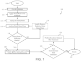
FIG. 1 is a flowchart of a method for producing a component in accordance with an embodiment; -
FIG. 2 schematically represents cross-sectional views of nickel-based superalloy substrates with a coating thereon before and after heat treatments in accordance with an embodiment; and -
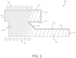
FIG. 3 includes a component that includes a nickel-based superalloy substrate and a coating thereon and illustrates a method of performing a heat treatment on the component to produce a microstructure having a grain size gradient in accordance with an embodiment of the invention. - The following detailed description is merely exemplary in nature and is not intended to limit the invention or the application and uses of the invention. As used herein, the word "exemplary" means "serving as an example, instance, or illustration." Thus, any embodiment described herein as "exemplary" is not necessarily to be construed as preferred or advantageous over other embodiments. All of the embodiments described herein are exemplary embodiments provided to enable persons skilled in the art to make or use the invention and not to limit the scope of the invention which is defined by the claims. Furthermore, there is no intention to be bound by any expressed or implied theory presented in the preceding technical field, background, brief summary, or the following detailed description.
- Methods disclosed herein that generally provide for producing components, such as gas turbine components, having a substrate with a protective coating system on a surface thereof. The methods provide for producing the components in a manner that is more efficient than certain prior art methods and that may preserve residual stress within the substrate imparted prior to forming the coating system.
- The substrates may include or be made from any type of alloy. For aerospace applications, the substrates may be made from a superalloy material due to their mechanical strength and resistance to high temperatures. For convenience, the method is described herein in reference to substrates comprising a nickel-based superalloy. However, it should be understood that the substrates may include or be formed of various other types of superalloys (e.g., cobalt-based, nickel-iron-based) or alloys (e.g., stainless steel). Nonlimiting examples of nickel-based superalloys include Ni-Cr-Fe-based (e.g., Inconels), Ni-Mo-Fe-based (e.g., Hastelloy A and B), and Ni-Cr-Mo-Fe-based (e.g., Hastelloy C and Hastelloy X). The substrates may have any regular or irregular shape and size.
- The coating system may include any number of layers each having different compositions, microstructures, and/or intended purposes. In various embodiments, one or more of the layers of the coating system may be configured to provide environmental protection to the underlying substrate, such as resistance to high temperatures and/or corrosion. In various embodiments, the coating system is configured to provide for resistance to hot corrosion caused by molten salts of sodium, magnesium, vanadium, and/or sulfur dioxide gas. In such embodiments, one or more layers of the coating system may be configured to react with the molten salts to increase a melting point of the molten salts thereby reducing deposition thereof on the component. In various embodiments, the coating system includes a glass material having different ratios of metal oxides such as, but not limited to, barium oxide, silicon oxide, strontium oxide, aluminum oxide, magnesium oxide, calcium oxide, cobalt oxide, and titanium oxide. The thickness of the coating system and/or individual layers thereof can vary. For example, the coating system may have a total thickness of between about 0.5 and 10 µm. Nonlimiting examples of coating systems that may be applied to the substrate are disclosed in
U.S. Patent No. 11,415,004 B2 to Mohajeri et al. - Referring now to
FIG. 1 , a flow chart is provided illustrating anexemplary method 100 for producing a component. Themethod 100 may start at 110. At 112, a substrate is provided, such as a superalloy substrate. In various embodiments, the substrate may be near net shape, that is, substantially similar in size and shape to the intended final size and shape of the component being produced. Various processes may be used to produce the substrate, including but not limited to various forging, milling, machining, casting, and/or powder metallurgy processes. In certain embodiments, the substrate may include residual stress imparted by one or more of these production processes. - Various material processing processes may be performed on the substrate. For example, the
method 100 may include performing a solution heat treatment on the substrate to dissolve precipitates in the substrate and to homogenize a microstructure of the substrate. Themethod 100 may include performing a stabilization heat treatment on the substrate to optimize a size and a morphology of precipitates therein, such as gamma prime phase precipitates, within the substrate. - After the substrate has been provided, the
method 100 may include applying, at 114, a slurry or paste to the substrate that is configured to form a coating thereon. The slurry or paste may be formed by various processes. For example, the slurry or paste may be made by mixing a fine glass powder with a carrier fluid and, optionally, additional components (e.g., binder, dispersant, etc.). Nonlimiting examples of slurries and pastes, as well as application methods thereof, are disclosed in Mohajeri et al. The slurry or paste may be applied onto desired surfaces of the substrate by, for example, brush painting, doctor-blading, screen printing, or spray painting. Low temperature volatile components of the slurry or paste may be removed during a drying step at 115, for example, in an oven. If present, organic compounds of the slurry or paste may be burned-out by a binder burnout process. - At 116, the
method 100 may include analyzing the coated substrate to determine whether the dried slurry or paste applied thereto is of sufficient quality to proceed. If the slurry or paste is insufficient (e.g., includes defects), an entirety or a portion of the slurry or paste may be locally removed to repair the slurry or paste at 120. Once a determination is made at 118 that the slurry or paste is of sufficient quality, themethod 100 may include simultaneously performing an aging process and a coating firing process in a single heat treatment at 122, referred to herein as a combination heat treatment. - The combination heat treatment may have various parameters, including various temperatures and durations, depending on the materials and desired result. Notably, the parameters of the combination heat treatment must be sufficient to both age the substrate to a desired degree (e.g., to achieve a specific hardness therein by controllably forming and/or modifying a size distribution of precipitates therein) as well as densifying and/or crystallizing the dried slurry or paste to a sufficient degree (e.g., to form a coating bonded to the surface of the substrate). In addition, the parameters of the combination heat treatment may be configured to avoid elimination of residual stress in the substrate (e.g., sufficiently low temperature and/or short duration). The precipitates formed in the substrate may be precipitates of an intermetallic phases, such as but not limited to a secondary gamma prime phase. In various embodiments, the combination heat treatment may include heating the substate having the dried slurry or paste to a temperature within a range of between about 750 and 850 °C and maintaining such temperature for a duration of between 8 to 32 hours. The combination heat treatment may be performed in a vacuum (e.g., less than about 1330 Pa), an inert atmosphere (e.g., argon, helium, hydrogen), and/or atmosphere having a different partial pressure of oxygen with respect to air.
- In various embodiments, the combination heat treatment may be performed by an induction heating process. The process may include generating a magnetic field around the substrate with an inductor connected to an electrical power source sufficient to induce eddy currents within the substrate and dissipate heat by Joule effect within the substrate. The electrical power source may be controlled while generating the magnetic field to provide the magnetic field for a duration of application of the magnetic field sufficient to directly induce the eddy currents within the substrate so as to produce a heat level therein to form and/or modify the size distribution of the precipitates. Exemplary but nonlimiting induction heating processes that may be adapted to perform the combination heat treatment are disclosed in
U.S. Patent No. 11,136,634 to Bridier et al. - In various embodiments, the
method 100 may include performing the combination heat treatment in a manner, or performing a subsequent heat treatment, to produce a dual microstructure within the substrate. For example, themethod 100 may include performing a localized induced heat treatment at 126 to controllably generate a coarse grain microstructure region within the component from a fine grain microstructure metallic component. In various embodiments, the component may be heat treated such that a core region thereof includes fine metallurgical grains configured to provide a desired fatigue resistance and a peripheral region thereof includes course metallurgical grains configured to provide a desired creep resistance. Exemplary but nonlimiting methods for producing such dual microstructures are disclosed in Bridier et al. - In various embodiments, the dual microstructure may be formed by generating a magnetic field around the coated substrate with an inductor connected to an electrical power source sufficient to induce eddy currents within the coated substrate and dissipate heat by Joule effect within the coated substrate, and controlling the electrical power source, by a processor, while generating the magnetic field to provide the magnetic field for a duration of application of the magnetic field sufficient to directly induce the eddy currents within the coated substrate so as to produce a heat level within the coated substrate to grow the grains. In general, the heat level may be lower to produce the fine grains and greater to produce the coarse grains. The grain growth may be further controlled by applying the slurry or paste in a manner such that a thickness of the coating on the surface varies across the surface. For example, the coating may be thicker over areas of the surface having the coarse grains and thinner over areas of the surface having the fine grains.
- Subsequent to producing the dual microstructure, or if such dual microstructure is not desired, the
method 100 may finish at 128. - Referring now to
FIG. 2 , a portion of a component is represented during production thereof which illustrates changes that occur during the heat treatment described at 122 of themethod 100 inFIG. 1 . Initially, asubstrate 210 is provided that is coated with a slurry orpaste 230. During the heat treatment, thesubstrate 210 is aged to produce thesubstrate 220 and the slurry orpaste 230 is converted into acoating 240. Importantly, an oxide layer is not formed on thesubstrate 220 as is common during aging processes performed on uncoated substrates. - Referring now to
FIG. 3 , anexemplary component 300 is represented that includes asubstrate 310 having acoating 312 thereon. Thesubstrate 310 includes a nickel-based superalloy having precipitates of a gamma prime phase therein and having a specific hardness. Thecoating 312 is bonded to exterior surfaces of thesubstrate 310 and is configured to provide resistance to hot corrosion caused by molten salts of sodium, magnesium, vanadium, and/or sulfur dioxide gas. In particular, thecoating 312 is configured to react with the molten salts to increase a melting point of the molten salts thereby reducing deposition thereof on thecomponent 300. Thesubstrate 310 includes residual stress therein that were imparted prior to forming thecoating 312. Since the residual stress was preserved, mechanical treatments were unnecessary subsequent to forming thecoating 312. Therefore, thecoating 312 has an as-formed structure free of mechanically induced defects. - In this example, the
component 300 includes a dual microstructure produced by controlling the induction heat treatment and the thickness of thecoating 312. Portions of thecomponent 300 directly treated by induction are represented as being located between a series ofsolid circles 330. Thecoating 312 includescoating portions coating 312 results in a dual microstructure wherein thecomponent 300 includes acoarse grain region 326 and afine grain region 328. As a nonlimiting example, thecoarse grain region 326 may have grains with a minimum or average grain size of greater than 20 µm and thefine grain region 328 may have grains with a maximum or average grain size of less than 20 µm. Thecomponent 300 may include additional grain regions between thecoarse grain region 326 and thefine grain region 328 having grain sizes that transition from the grain sizes of thecoarse grain region 326 to the grain sizes of thefine grain region 328. - The
component 300 is configured to be installed in a gas turbine engine. For example, thecomponent 300 may be a shroud. - The methods disclosed herein and components formed therewith provide various benefits over certain existing methods and components. For example, use of the combination heat treatment combines two heat treatment processes into one heat treatment process which reduces the steps necessary to produce the components, thereby potentially reducing the cost and time required for production thereof. Further, aging the substrate with the coating thereon prevents or reduces the likelihood of the formation of an oxide layer on the substrate. This in turn avoids the necessity of removing such oxide layer and therefore further reduces the number of steps necessary to produce the component.
- The methods may provide for producing components having novel properties. For example, the methods allow for maintaining residual stress within the substrate during the coating formation process unlike certain prior art process, for example, that cause diffusion between the coating and the surface. In such embodiments, subsequent mechanical treatments may be omitted and therefore, the coating may be free of surface defects (e.g., scratches, abrasions, etc.) that may be created by such treatments. This may allow for the coating to exhibit improved performance relative to comparable coatings having such defects.
- In this document, relational terms such as first and second, and the like may be used solely to distinguish one entity or action from another entity or action without necessarily requiring or implying any actual such relationship or order between such entities or actions. Numerical ordinals such as "first," "second," "third," etc. simply denote different singles of a plurality and do not imply any order or sequence unless specifically defined by the claim language. The sequence of the text in any of the claims does not imply that process steps must be performed in a temporal or logical order according to such sequence unless it is specifically defined by the language of the claim. The process steps may be interchanged in any order without departing from the scope of the invention as long as such an interchange does not contradict the claim language and is not logically nonsensical.
- Furthermore, depending on the context, words such as "connect" or "coupled to" used in describing a relationship between different elements do not imply that a direct physical connection must be made between these elements. For example, two elements may be connected to each other physically, electronically, logically, or in any other manner, through one or more additional elements.
- While at least one exemplary embodiment has been presented in the foregoing detailed description of the invention, it should be appreciated that a vast number of variations exist. It should also be appreciated that the exemplary embodiment or exemplary embodiments are only examples, and are not intended to limit the scope, applicability, or configuration of the invention in any way. Rather, the foregoing detailed description will provide those skilled in the art with a convenient road map for implementing an exemplary embodiment of the invention. It being understood that various changes may be made in the function and arrangement of elements described in an exemplary embodiment without departing from the scope of the invention as set forth in the appended claims.
Claims (15)
- A method for producing a component, the method comprising:applying a slurry or paste to a surface of a substrate, wherein the substrate includes a nickel-based superalloy;drying the slurry or paste applied to the surface to define a coated substrate; andperforming a heat treatment on the coated substrate to simultaneously densify and/or crystallize the dried slurry or paste to thereby form a coating that is bonded to the surface and to age the substrate to achieve a specific hardness therein by controllably forming precipitates of an intermetallic phase within the substrate and/or controllably modifying a size distribution of the precipitates of the intermetallic phase within the substrate,wherein residual stress within the substrate are preserved during the heat treatment.
- The method of claim 1, wherein the coating is configured for resistance to hot corrosion caused by molten salts of sodium, magnesium, vanadium, and/or sulfur dioxide gas, wherein the coating is configured to react with the molten salts to increase a melting point of the molten salts thereby reducing deposition thereof on the component.
- The method of claim 1, wherein the coating comprises a mixture of two or more metal oxides, which are selected from the group consisting of: barium oxide, silicon oxide, strontium oxide, aluminum oxide, magnesium oxide, calcium oxide, cobalt oxide, boron oxide, iron oxide, zirconium oxide, nickel oxide, and titanium oxide, wherein the coating is in fully crystalline form and/or a mixture of crystalline and glass phases.
- The method of claim 1, wherein the component is configured to be installed in a gas turbine engine.
- The method of claim 1, wherein performing the heat treatment on the substrate comprises:generating a magnetic field around the substrate with an inductor connected to an electrical power source sufficient to induce eddy currents within the substrate and dissipate heat by Joule effect within the substrate; andcontrolling the electrical power source while generating the magnetic field to provide the magnetic field for a duration of application of the magnetic field sufficient to directly induce the eddy currents within the substrate so as to produce a heat level within the substrate to form the precipitates.
- The method of claim 1, further comprising producing the substrate such that the substrate has a final net shape and dimension prior to applying the slurry or coating to the surface of the substrate, wherein producing the substrate results in the residual stress within the substrate.
- The method of claim 6, further comprising:performing a solution heat treatment on the substrate to dissolve other precipitates in the component and to homogenize a microstructure of the substrate; andperforming a stabilization heat treatment to optimize a size and a morphology of the precipitates of the intermetallic phase within the substrate.
- The method of claim 1, wherein performing the heat treatment comprises increasing and maintaining the temperature of the substrate to a temperature range of between 750 and 850 °C for a duration of between 8 to 32 hours in a vacuum, an inert atmosphere, and/or atmosphere having a different partial pressure of oxygen with respect to air.
- The method of claim 1, wherein performing the heat treatment produces a microstructure in the substrate having a grain size gradient that transitions from fine grains having a grain size of less than 20 µm to coarse grains having a grain size of greater than 20 µm.
- The method of claim 9, wherein performing the heat treatment includes controlling the grain sizes of the microstructure of the substrate by:generating a magnetic field around the substrate with an inductor connected to an electrical power source sufficient to induce eddy currents within the substrate and dissipate heat by Joule effect within the substrate;controlling the electrical power source, by the processor, while generating the magnetic field to provide the magnetic field for a duration of application of the magnetic field sufficient to directly induce the eddy currents within the substrate so as to produce a heat level within the substrate to grow the grains,wherein the heat level is lower to produce the fine grains and greater to produce the coarse grains; andapplying the slurry or paste in a manner such that a thickness of the coating on the surface varies across the surface, wherein the coating is thicker over areas of the surface having the coarse grains and thinner over areas of the surface having the fine grains.
- A component comprising:a substrate comprising a nickel-based superalloy having precipitates of an intermetallic phase, the substrate having a specific hardness therein; anda coating bonded to a surface of the substrate, the coating configured for resistance to hot corrosion caused by molten salts of sodium, magnesium, vanadium, and/or sulfur dioxide gas, wherein the coating is configured to react with the molten salts to increase a melting point of the molten salts thereby reducing deposition thereof on the component,wherein the substrate includes residual stress therein,wherein the coating has an as-formed structure free of mechanically induced defects created during production of the component.
- The component of claim 11, wherein the coating comprises a mixture of two or more metal oxides, which are selected from the group consisting of: barium oxide, silicon oxide, strontium oxide, aluminum oxide, magnesium oxide, calcium oxide, cobalt oxide, boron oxide, iron oxide, zirconium oxide, nickel oxide, and titanium oxide, wherein the coating is in fully crystalline form and/or a mixture of crystalline and glass phases.
- The component of claim 11, wherein the component is configured to be installed in a gas turbine engine.
- The component of claim 11, wherein a microstructure of the substrate has a grain size gradient that transitions from fine grains having a grain size of less than 20 µm to coarse grains having a grain size of greater than 20 µm.
- The component of claim 11, wherein the component is formed by a method comprising:applying a slurry or paste to the surface of the substrate;drying the slurry or paste applied to the surface to form a coated substrate; andperforming a heat treatment on the dried slurry or paste to simultaneously densify and/or crystallize the dried slurry or paste to thereby form the coating and to age the substrate to achieve the specific hardness therein by controllably forming the precipitates of the intermetallic phase within the substrate and/or controllably modifying a size distribution of the precipitates of the intermetallic phase within the substrate,wherein the residual stress within the substrate are preserved during the heat treatment.
Applications Claiming Priority (1)
| Application Number | Priority Date | Filing Date | Title |
|---|---|---|---|
| US202218146802A | 2022-12-27 | 2022-12-27 |
Publications (1)
| Publication Number | Publication Date |
|---|---|
| EP4394082A1 true EP4394082A1 (en) | 2024-07-03 |
Family
ID=89119201
Family Applications (1)
| Application Number | Title | Priority Date | Filing Date |
|---|---|---|---|
| EP23214207.5A Pending EP4394082A1 (en) | 2022-12-27 | 2023-12-05 | Superalloy components having coatings thereon and methods for producing the same |
Country Status (1)
| Country | Link |
|---|---|
| EP (1) | EP4394082A1 (en) |
Citations (5)
| Publication number | Priority date | Publication date | Assignee | Title |
|---|---|---|---|---|
| US20090297718A1 (en) * | 2008-05-29 | 2009-12-03 | General Electric Company | Methods of fabricating environmental barrier coatings for silicon based substrates |
| WO2017106970A1 (en) * | 2015-12-22 | 2017-06-29 | École De Technologie Supérieure | A method for heat treating by induction an alloy component for generating microstructure gradients and an alloy component heat treated according to the method |
| EP3473608A1 (en) * | 2017-10-20 | 2019-04-24 | United Technologies Corporation | Processes for coating articles and coated articles |
| US20200230645A1 (en) * | 2018-06-01 | 2020-07-23 | Rolls-Royce North American Technologies, Inc. | Slurry-based coating system repair |
| US11415004B2 (en) | 2020-12-09 | 2022-08-16 | Honeywell International Inc. | Corrosion and oxidation resistant coatings for gas turbine engines, and methods for producing the same |
-
2023
- 2023-12-05 EP EP23214207.5A patent/EP4394082A1/en active Pending
Patent Citations (6)
| Publication number | Priority date | Publication date | Assignee | Title |
|---|---|---|---|---|
| US20090297718A1 (en) * | 2008-05-29 | 2009-12-03 | General Electric Company | Methods of fabricating environmental barrier coatings for silicon based substrates |
| WO2017106970A1 (en) * | 2015-12-22 | 2017-06-29 | École De Technologie Supérieure | A method for heat treating by induction an alloy component for generating microstructure gradients and an alloy component heat treated according to the method |
| US11136634B2 (en) | 2015-12-22 | 2021-10-05 | École De Technologie Supérieure | Method for heat treating by induction an alloy component for generating microstructure gradients and an alloy component heat treated according to the method |
| EP3473608A1 (en) * | 2017-10-20 | 2019-04-24 | United Technologies Corporation | Processes for coating articles and coated articles |
| US20200230645A1 (en) * | 2018-06-01 | 2020-07-23 | Rolls-Royce North American Technologies, Inc. | Slurry-based coating system repair |
| US11415004B2 (en) | 2020-12-09 | 2022-08-16 | Honeywell International Inc. | Corrosion and oxidation resistant coatings for gas turbine engines, and methods for producing the same |
Similar Documents
| Publication | Publication Date | Title |
|---|---|---|
| US10315218B2 (en) | Method for repairing turbine component by application of thick cold spray coating | |
| US11047016B2 (en) | Techniques for controlling precipitate phase domain size in an alloy | |
| EP2604723B1 (en) | Cold spray of nickel-base alloys | |
| US11371120B2 (en) | Cobalt-nickel base alloy and method of making an article therefrom | |
| US5498484A (en) | Thermal barrier coating system with hardenable bond coat | |
| US6964791B2 (en) | High-temperature articles and method for making | |
| US5712050A (en) | Superalloy component with dispersion-containing protective coating | |
| CN102816953A (en) | Alumina-Forming Cobalt-Nickel Base Alloy and Method of Making an Article Therefrom | |
| US4512817A (en) | Method for producing corrosion resistant high strength superalloy articles | |
| EP3181727B1 (en) | Coated articles | |
| EP3357605B1 (en) | Manufacturing method and post-processing treatment | |
| JP2020517821A (en) | Precipitation hardened cobalt-nickel based superalloys and articles made therefrom | |
| US8252376B2 (en) | Method for restoring the microstructure of a textured article and for refurbishing a gas turbine blade or vane | |
| CN113242913A (en) | Turbine component made of a rhenium and/or ruthenium containing superalloy and associated manufacturing method | |
| EP4012068A1 (en) | Corrosion and oxidation resistant coatings for gas turbine engines, and methods for producing the same | |
| JP2003034853A (en) | HEAT TREATMENT METHOD FOR Ni-BASED ALLOY | |
| US6565672B2 (en) | Fabrication of an article having a protective coating with a flattened, pre-oxidized protective-coating surface | |
| US20030062099A1 (en) | Method for restoring the microstructure of a textured article and for refurbishing a gas turbine blade or vane | |
| JPH05195186A (en) | Superalloy product having protective coating containing dispersion and method of making same | |
| US20080138648A1 (en) | Layer system with blocking layer, and production process | |
| CN119304035B (en) | Bending correcting process for rhenium alloy plate | |
| US20100260613A1 (en) | Process for preventing the formation of secondary reaction zone in susceptible articles, and articles manufactured using same | |
| Wahl et al. | An overview of advanced Ni-base superalloys for small turbines and missile Engine applications | |
| JPH10195629A (en) | Gas turbine blade and method for forming film thereon |
Legal Events
| Date | Code | Title | Description |
|---|---|---|---|
| PUAI | Public reference made under article 153(3) epc to a published international application that has entered the european phase |
Free format text: ORIGINAL CODE: 0009012 |
|
| STAA | Information on the status of an ep patent application or granted ep patent |
Free format text: STATUS: THE APPLICATION HAS BEEN PUBLISHED |
|
| AK | Designated contracting states |
Kind code of ref document: A1 Designated state(s): AL AT BE BG CH CY CZ DE DK EE ES FI FR GB GR HR HU IE IS IT LI LT LU LV MC ME MK MT NL NO PL PT RO RS SE SI SK SM TR |
|
| P01 | Opt-out of the competence of the unified patent court (upc) registered |
Free format text: CASE NUMBER: APP_41632/2024 Effective date: 20240715 |
|
| STAA | Information on the status of an ep patent application or granted ep patent |
Free format text: STATUS: REQUEST FOR EXAMINATION WAS MADE |
|
| 17P | Request for examination filed |
Effective date: 20250102 |