EP4393777A1 - Power supply system for vehicle - Google Patents
Power supply system for vehicle Download PDFInfo
- Publication number
- EP4393777A1 EP4393777A1 EP22861163.8A EP22861163A EP4393777A1 EP 4393777 A1 EP4393777 A1 EP 4393777A1 EP 22861163 A EP22861163 A EP 22861163A EP 4393777 A1 EP4393777 A1 EP 4393777A1
- Authority
- EP
- European Patent Office
- Prior art keywords
- unit
- switch
- energization
- battery
- electrical load
- Prior art date
- Legal status (The legal status is an assumption and is not a legal conclusion. Google has not performed a legal analysis and makes no representation as to the accuracy of the status listed.)
- Pending
Links
Images





Classifications
-
- B—PERFORMING OPERATIONS; TRANSPORTING
- B60—VEHICLES IN GENERAL
- B60L—PROPULSION OF ELECTRICALLY-PROPELLED VEHICLES; SUPPLYING ELECTRIC POWER FOR AUXILIARY EQUIPMENT OF ELECTRICALLY-PROPELLED VEHICLES; ELECTRODYNAMIC BRAKE SYSTEMS FOR VEHICLES IN GENERAL; MAGNETIC SUSPENSION OR LEVITATION FOR VEHICLES; MONITORING OPERATING VARIABLES OF ELECTRICALLY-PROPELLED VEHICLES; ELECTRIC SAFETY DEVICES FOR ELECTRICALLY-PROPELLED VEHICLES
- B60L58/00—Methods or circuit arrangements for monitoring or controlling batteries or fuel cells, specially adapted for electric vehicles
- B60L58/10—Methods or circuit arrangements for monitoring or controlling batteries or fuel cells, specially adapted for electric vehicles for monitoring or controlling batteries
- B60L58/18—Methods or circuit arrangements for monitoring or controlling batteries or fuel cells, specially adapted for electric vehicles for monitoring or controlling batteries of two or more battery modules
- B60L58/19—Switching between serial connection and parallel connection of battery modules
-
- B—PERFORMING OPERATIONS; TRANSPORTING
- B60—VEHICLES IN GENERAL
- B60L—PROPULSION OF ELECTRICALLY-PROPELLED VEHICLES; SUPPLYING ELECTRIC POWER FOR AUXILIARY EQUIPMENT OF ELECTRICALLY-PROPELLED VEHICLES; ELECTRODYNAMIC BRAKE SYSTEMS FOR VEHICLES IN GENERAL; MAGNETIC SUSPENSION OR LEVITATION FOR VEHICLES; MONITORING OPERATING VARIABLES OF ELECTRICALLY-PROPELLED VEHICLES; ELECTRIC SAFETY DEVICES FOR ELECTRICALLY-PROPELLED VEHICLES
- B60L3/00—Electric devices on electrically-propelled vehicles for safety purposes; Monitoring operating variables, e.g. speed, deceleration or energy consumption
- B60L3/0023—Detecting, eliminating, remedying or compensating for drive train abnormalities, e.g. failures within the drive train
- B60L3/0046—Detecting, eliminating, remedying or compensating for drive train abnormalities, e.g. failures within the drive train relating to electric energy storage systems, e.g. batteries or capacitors
-
- B—PERFORMING OPERATIONS; TRANSPORTING
- B60—VEHICLES IN GENERAL
- B60L—PROPULSION OF ELECTRICALLY-PROPELLED VEHICLES; SUPPLYING ELECTRIC POWER FOR AUXILIARY EQUIPMENT OF ELECTRICALLY-PROPELLED VEHICLES; ELECTRODYNAMIC BRAKE SYSTEMS FOR VEHICLES IN GENERAL; MAGNETIC SUSPENSION OR LEVITATION FOR VEHICLES; MONITORING OPERATING VARIABLES OF ELECTRICALLY-PROPELLED VEHICLES; ELECTRIC SAFETY DEVICES FOR ELECTRICALLY-PROPELLED VEHICLES
- B60L3/00—Electric devices on electrically-propelled vehicles for safety purposes; Monitoring operating variables, e.g. speed, deceleration or energy consumption
- B60L3/0023—Detecting, eliminating, remedying or compensating for drive train abnormalities, e.g. failures within the drive train
- B60L3/0084—Detecting, eliminating, remedying or compensating for drive train abnormalities, e.g. failures within the drive train relating to control modules
-
- B—PERFORMING OPERATIONS; TRANSPORTING
- B60—VEHICLES IN GENERAL
- B60L—PROPULSION OF ELECTRICALLY-PROPELLED VEHICLES; SUPPLYING ELECTRIC POWER FOR AUXILIARY EQUIPMENT OF ELECTRICALLY-PROPELLED VEHICLES; ELECTRODYNAMIC BRAKE SYSTEMS FOR VEHICLES IN GENERAL; MAGNETIC SUSPENSION OR LEVITATION FOR VEHICLES; MONITORING OPERATING VARIABLES OF ELECTRICALLY-PROPELLED VEHICLES; ELECTRIC SAFETY DEVICES FOR ELECTRICALLY-PROPELLED VEHICLES
- B60L3/00—Electric devices on electrically-propelled vehicles for safety purposes; Monitoring operating variables, e.g. speed, deceleration or energy consumption
- B60L3/04—Cutting off the power supply under fault conditions
-
- B—PERFORMING OPERATIONS; TRANSPORTING
- B60—VEHICLES IN GENERAL
- B60L—PROPULSION OF ELECTRICALLY-PROPELLED VEHICLES; SUPPLYING ELECTRIC POWER FOR AUXILIARY EQUIPMENT OF ELECTRICALLY-PROPELLED VEHICLES; ELECTRODYNAMIC BRAKE SYSTEMS FOR VEHICLES IN GENERAL; MAGNETIC SUSPENSION OR LEVITATION FOR VEHICLES; MONITORING OPERATING VARIABLES OF ELECTRICALLY-PROPELLED VEHICLES; ELECTRIC SAFETY DEVICES FOR ELECTRICALLY-PROPELLED VEHICLES
- B60L58/00—Methods or circuit arrangements for monitoring or controlling batteries or fuel cells, specially adapted for electric vehicles
- B60L58/10—Methods or circuit arrangements for monitoring or controlling batteries or fuel cells, specially adapted for electric vehicles for monitoring or controlling batteries
- B60L58/12—Methods or circuit arrangements for monitoring or controlling batteries or fuel cells, specially adapted for electric vehicles for monitoring or controlling batteries responding to state of charge [SoC]
-
- B—PERFORMING OPERATIONS; TRANSPORTING
- B60—VEHICLES IN GENERAL
- B60R—VEHICLES, VEHICLE FITTINGS, OR VEHICLE PARTS, NOT OTHERWISE PROVIDED FOR
- B60R16/00—Electric or fluid circuits specially adapted for vehicles and not otherwise provided for; Arrangement of elements of electric or fluid circuits specially adapted for vehicles and not otherwise provided for
- B60R16/02—Electric or fluid circuits specially adapted for vehicles and not otherwise provided for; Arrangement of elements of electric or fluid circuits specially adapted for vehicles and not otherwise provided for electric constitutive elements
-
- B—PERFORMING OPERATIONS; TRANSPORTING
- B60—VEHICLES IN GENERAL
- B60R—VEHICLES, VEHICLE FITTINGS, OR VEHICLE PARTS, NOT OTHERWISE PROVIDED FOR
- B60R16/00—Electric or fluid circuits specially adapted for vehicles and not otherwise provided for; Arrangement of elements of electric or fluid circuits specially adapted for vehicles and not otherwise provided for
- B60R16/02—Electric or fluid circuits specially adapted for vehicles and not otherwise provided for; Arrangement of elements of electric or fluid circuits specially adapted for vehicles and not otherwise provided for electric constitutive elements
- B60R16/03—Electric or fluid circuits specially adapted for vehicles and not otherwise provided for; Arrangement of elements of electric or fluid circuits specially adapted for vehicles and not otherwise provided for electric constitutive elements for supply of electrical power to vehicle subsystems or for
-
- H—ELECTRICITY
- H02—GENERATION; CONVERSION OR DISTRIBUTION OF ELECTRIC POWER
- H02H—EMERGENCY PROTECTIVE CIRCUIT ARRANGEMENTS
- H02H7/00—Emergency protective circuit arrangements specially adapted for specific types of electric machines or apparatus or for sectionalised protection of cable or line systems, and effecting automatic switching in the event of an undesired change from normal working conditions
- H02H7/18—Emergency protective circuit arrangements specially adapted for specific types of electric machines or apparatus or for sectionalised protection of cable or line systems, and effecting automatic switching in the event of an undesired change from normal working conditions for batteries; for accumulators
-
- H—ELECTRICITY
- H02—GENERATION; CONVERSION OR DISTRIBUTION OF ELECTRIC POWER
- H02J—ELECTRIC POWER NETWORKS; CIRCUIT ARRANGEMENTS OR SYSTEMS FOR SUPPLYING OR DISTRIBUTING ELECTRIC POWER; SYSTEMS FOR STORING ELECTRIC ENERGY
- H02J7/00—Circuit arrangements for charging or discharging batteries or for supplying loads from batteries
-
- H—ELECTRICITY
- H02—GENERATION; CONVERSION OR DISTRIBUTION OF ELECTRIC POWER
- H02J—ELECTRIC POWER NETWORKS; CIRCUIT ARRANGEMENTS OR SYSTEMS FOR SUPPLYING OR DISTRIBUTING ELECTRIC POWER; SYSTEMS FOR STORING ELECTRIC ENERGY
- H02J7/00—Circuit arrangements for charging or discharging batteries or for supplying loads from batteries
- H02J7/34—Parallel operation in networks using both storage and other DC sources, e.g. providing buffering
-
- H—ELECTRICITY
- H02—GENERATION; CONVERSION OR DISTRIBUTION OF ELECTRIC POWER
- H02J—ELECTRIC POWER NETWORKS; CIRCUIT ARRANGEMENTS OR SYSTEMS FOR SUPPLYING OR DISTRIBUTING ELECTRIC POWER; SYSTEMS FOR STORING ELECTRIC ENERGY
- H02J7/00—Circuit arrangements for charging or discharging batteries or for supplying loads from batteries
- H02J7/34—Parallel operation in networks using both storage and other DC sources, e.g. providing buffering
- H02J7/345—Parallel operation in networks using both storage and other DC sources, e.g. providing buffering using capacitors as storage or buffering devices
-
- H—ELECTRICITY
- H02—GENERATION; CONVERSION OR DISTRIBUTION OF ELECTRIC POWER
- H02J—ELECTRIC POWER NETWORKS; CIRCUIT ARRANGEMENTS OR SYSTEMS FOR SUPPLYING OR DISTRIBUTING ELECTRIC POWER; SYSTEMS FOR STORING ELECTRIC ENERGY
- H02J7/00—Circuit arrangements for charging or discharging batteries or for supplying loads from batteries
- H02J7/50—Circuit arrangements for charging or discharging batteries or for supplying loads from batteries acting upon multiple batteries simultaneously or sequentially
- H02J7/575—Parallel/serial switching of connection of batteries to charge or load circuit
-
- H—ELECTRICITY
- H02—GENERATION; CONVERSION OR DISTRIBUTION OF ELECTRIC POWER
- H02J—ELECTRIC POWER NETWORKS; CIRCUIT ARRANGEMENTS OR SYSTEMS FOR SUPPLYING OR DISTRIBUTING ELECTRIC POWER; SYSTEMS FOR STORING ELECTRIC ENERGY
- H02J7/00—Circuit arrangements for charging or discharging batteries or for supplying loads from batteries
- H02J7/60—Circuit arrangements for charging or discharging batteries or for supplying loads from batteries including safety or protection arrangements
- H02J7/62—Circuit arrangements for charging or discharging batteries or for supplying loads from batteries including safety or protection arrangements against overcurrent
-
- H—ELECTRICITY
- H02—GENERATION; CONVERSION OR DISTRIBUTION OF ELECTRIC POWER
- H02J—ELECTRIC POWER NETWORKS; CIRCUIT ARRANGEMENTS OR SYSTEMS FOR SUPPLYING OR DISTRIBUTING ELECTRIC POWER; SYSTEMS FOR STORING ELECTRIC ENERGY
- H02J7/00—Circuit arrangements for charging or discharging batteries or for supplying loads from batteries
- H02J7/80—Circuit arrangements for charging or discharging batteries or for supplying loads from batteries including monitoring or indicating arrangements
- H02J7/82—Control of state of charge [SOC]
-
- H—ELECTRICITY
- H02—GENERATION; CONVERSION OR DISTRIBUTION OF ELECTRIC POWER
- H02J—ELECTRIC POWER NETWORKS; CIRCUIT ARRANGEMENTS OR SYSTEMS FOR SUPPLYING OR DISTRIBUTING ELECTRIC POWER; SYSTEMS FOR STORING ELECTRIC ENERGY
- H02J7/00—Circuit arrangements for charging or discharging batteries or for supplying loads from batteries
- H02J7/855—Circuit arrangements for charging or discharging batteries or for supplying loads from batteries with circuits adapted for supplying loads from the battery
-
- H—ELECTRICITY
- H02—GENERATION; CONVERSION OR DISTRIBUTION OF ELECTRIC POWER
- H02J—ELECTRIC POWER NETWORKS; CIRCUIT ARRANGEMENTS OR SYSTEMS FOR SUPPLYING OR DISTRIBUTING ELECTRIC POWER; SYSTEMS FOR STORING ELECTRIC ENERGY
- H02J7/00—Circuit arrangements for charging or discharging batteries or for supplying loads from batteries
- H02J7/90—Regulation of charging or discharging current or voltage
- H02J7/933—Regulation of charging or discharging current or voltage the cycle being controlled or terminated in response to electric parameters
-
- B—PERFORMING OPERATIONS; TRANSPORTING
- B60—VEHICLES IN GENERAL
- B60L—PROPULSION OF ELECTRICALLY-PROPELLED VEHICLES; SUPPLYING ELECTRIC POWER FOR AUXILIARY EQUIPMENT OF ELECTRICALLY-PROPELLED VEHICLES; ELECTRODYNAMIC BRAKE SYSTEMS FOR VEHICLES IN GENERAL; MAGNETIC SUSPENSION OR LEVITATION FOR VEHICLES; MONITORING OPERATING VARIABLES OF ELECTRICALLY-PROPELLED VEHICLES; ELECTRIC SAFETY DEVICES FOR ELECTRICALLY-PROPELLED VEHICLES
- B60L2240/00—Control parameters of input or output; Target parameters
- B60L2240/40—Drive Train control parameters
- B60L2240/54—Drive Train control parameters related to batteries
- B60L2240/549—Current
-
- Y—GENERAL TAGGING OF NEW TECHNOLOGICAL DEVELOPMENTS; GENERAL TAGGING OF CROSS-SECTIONAL TECHNOLOGIES SPANNING OVER SEVERAL SECTIONS OF THE IPC; TECHNICAL SUBJECTS COVERED BY FORMER USPC CROSS-REFERENCE ART COLLECTIONS [XRACs] AND DIGESTS
- Y02—TECHNOLOGIES OR APPLICATIONS FOR MITIGATION OR ADAPTATION AGAINST CLIMATE CHANGE
- Y02E—REDUCTION OF GREENHOUSE GAS [GHG] EMISSIONS, RELATED TO ENERGY GENERATION, TRANSMISSION OR DISTRIBUTION
- Y02E60/00—Enabling technologies; Technologies with a potential or indirect contribution to GHG emissions mitigation
- Y02E60/10—Energy storage using batteries
Definitions
- the present disclosure relates to a vehicular power supply system.
- Power supply systems have been known which include a sensor unit that detects a state (voltage, current, ground fault, and the like) of a storage battery, and an ECU that receives a detection result from the sensor unit and controls, based on the received detection result, on/off operation of a relay switch that switches between energization and interruption of energization between the storage battery and an electrical load (including a generator such as a rotary electric machine) (e.g., PTL 1).
- a sensor unit that detects a state (voltage, current, ground fault, and the like) of a storage battery
- an ECU that receives a detection result from the sensor unit and controls, based on the received detection result, on/off operation of a relay switch that switches between energization and interruption of energization between the storage battery and an electrical load (including a generator such as a rotary electric machine) (e.g., PTL 1).
- the relay switch is typically turned off to interrupt energization between the storage battery and the electrical load, thereby ensuring safety.
- the present disclosure has an object of providing a vehicular power supply system that can supply electrical power from a storage battery for a certain time even when communication is broken.
- a first means for solving the above problem is a vehicular power supply system including a sensor unit that detects a battery state of a storage battery that is capable of supplying electrical power to an electrical load, and a control unit that receives the battery state from the sensor unit via a communication path and performs instruction to perform energization and interruption of the energization between the storage battery and the electrical load based on the received battery state, wherein the sensor unit includes: a detection unit that detects the battery state of the storage battery; a switch drive unit that performs drive control of a switch unit provided between the storage battery and the electrical load; and a control unit that controls the switch drive unit, the control unit controls the switch drive unit based on the instruction from the control unit to switch between the energization and interruption of the energization between the storage battery and the electrical load, and if determining an abnormality in the control unit or the communication path, the control unit determines whether to maintain the energization between the storage battery and the electrical load based on the battery state detected by the detection
- the control unit determines whether to maintain the energization between the storage battery and the electrical load based on the battery state detected by the detection unit and performs drive control of the switch unit based on the determination. Hence, if no abnormality has been caused in the storage battery, electrical power can be supplied from the storage battery to the electrical load for a certain time.
- a second means for solving the above problem is a vehicular power supply system including a sensor unit that detects a battery state of a storage battery that is capable of supplying electrical power to an electrical load, and a control unit that receives the battery state from the sensor unit via a communication path and performs instruction to perform energization and interruption of the energization between the storage battery and the electrical load based on the received battery state, wherein the sensor unit includes: a detection unit that detects the battery state of the storage battery; and a switch drive unit that performs drive control of a switch unit provided between the storage battery and the electrical load based on the instruction of the control unit to switch between the energization and the interruption of the energization between the storage battery and the electrical load, the control unit is configured to, in a normal state, output a notification signal indicating the normal state every time a certain time period has elapsed, and if receiving the notification signal from the control unit every time the certain time period has elapsed, the switch drive unit maintains the en
- the notification signal is not input to the switch drive unit.
- the switch drive unit determines that an abnormality has caused and performs drive control of the switch unit to interrupt the energization between the storage battery and the electrical load after the predetermined allowable time has elapsed.
- electrical power can be supplied from the storage battery to the electrical load for a certain time.
- the sensor unit 20 includes a current detection unit 21 that detects a current of the battery module 11, which is a detection target, and a voltage detection unit 22 that detects a voltage of the battery module 11, which is a detection target.
- a switch 23a is provided which is a switch unit that switches between energization and interruption of energization between the battery module 11, which is a detection target, and the electrical load 13.
- the sensor unit 20 includes a switch drive unit 23 that performs on/off-control of the switch 23a.
- the switch 23a is, for example, a relay switch.
- the switch 23a may be implemented by a pyro fuse.
- the MCU 31 outputs a notification signal for making a notification that the control unit 30 and the communication path L38 are normal every time a certain time period T1 has elapsed.
- the certain time period T1 may be any time period, for example, 5 minutes.
- step S201 determines that an abnormality is caused in the communication path L38, the MCU 31, or the like (step S204). Then, the switch drive unit 23 maintains an on state of the switch 23a until a predetermined allowable time Ton elapses (step s205).
- the allowable time To is a time period (e.g. about five minutes) during which the own vehicle can be moved to the side of the road at which no obstruction to travel of other vehicles is caused, and is preferably as short as possible.
- the switch drive unit 23 changes the switch 23a to an off state to interrupt energization of the battery module 11 (step s206).
- the configuration of the control unit 30 according to the third embodiment will be described.
- the MCU 31 of the control unit 30 performs a switch drive instruction process illustrated in FIG. 7 at predetermined intervals.
- the MCU 31 determines whether the communication path L38 and the sensor unit 20 are normal (step S301). Specifically, the MCU 31 detects a disconnection of the communication path L38 (including an abnormality of elements provided to the communication path L38) and an abnormality of the sensor unit 20.
- the method of detecting a disconnection of the communication path L38 is similar to that of the first embodiment.
- An abnormality of the sensor unit 20 can be detected by various methods, for example, when there is no response from the sensor unit 20, or when an abnormality signal is received from the sensor unit 20. These abnormality determination methods may be well-known methods.
- the MCU 31 stops supplying drive electrical power to the sensor unit 20 (step S305). Hence, since the switch drive unit 23 cannot maintain the on state of the switch 23a, the switch 23a is changed to an off state. As a result, the energization between the battery module 11 and the electrical load 13 is interrupted.
- step S303 determines whether the battery module 11 and the electrical load 13 is interrupted. If the determination result of step S303 is affirmative, the MCU 31 proceeds to step S305 to stop supplying drive electrical power to the sensor unit 20. Hence, as described above, the energization between the battery module 11 and the electrical load 13 is interrupted.
- the configuration of the above first embodiment may be modified as the following fourth embodiment.
- the third embodiment part different from the configurations described in the above embodiments will be mainly described.
- the fourth embodiment as a basic configuration, the vehicular power supply system 100 of the first embodiment will be exemplified.
- the sensor unit 20 includes a plurality of (two in the present embodiment) current detection unit 21. It is noted that, unlike the first embodiment, the voltage detection unit 22 may be included or not be included.
- the two current detection units 21 detect currents at different positions.
- a first current detection unit 21a and a second current detection unit 21b are included.
- the first current detection unit 21a detects a current (first current value) at a first position P1 in the vicinity of the battery module 11 on the electrical path, which is a detection target, of the sensor unit 20.
- the second current detection unit 21b is farther from the battery module 11 than the first current detection unit 21a and detects a current (second current value) at a second position P2 in the vicinity of the switch 23a on the electrical path.
- the first current detection unit 21a detects a current at the first position P1. If the value of the current is a predetermined first threshold value or greater, the first current detection unit 21a outputs a first detection signal indicating this.
- the second current detection unit 21b detects a current at the second position P2. If the value of the current is a predetermined second threshold value or greater, the second current detection unit 21b outputs a second detection signal indicating this.
- the first threshold value and the second threshold value are set to the same value Th.
- the configuration of the above fourth embodiment may be modified as the following fifth embodiment.
- part different from the configurations described in the above embodiments will be mainly described.
- the vehicular power supply system 100 of the fourth embodiment will be exemplified.
- a discharge circuit 51 for quickly discharging charge of the capacitor C1 is provided between the battery module 11 and the electrical load 13.
- the discharge circuit 51 is connected with the capacitor C1, the battery module 11, and the electrical load 13 in parallel.
- the discharge circuit 51 is configured of a series connection of a resistor R10 and a switch 23b.
- the switch 23b is normally set so as to be an off state (energization interruption state).
- the sensor unit 20 of the fifth embodiment includes, as in the fourth embodiment, the first current detection unit 21a, the second current detection unit 21b, the AND circuit AND1, and the switch drive unit 231.
- the sensor units 20 of the fifth embodiment includes, in addition to the above configuration, a second switch drive unit 232. It is noted, in the fifth embodiment, the switch drive unit 231 is referred to as a first switch drive unit 231 as a matter of convenience.
- the second switch drive unit 232 is connected to an output terminal of the AND circuit AND1 via a delay circuit D1. As illustrated in FIG. 11 , if the first detection signal and the second detection signal are input to the AND circuit AND1, and the AND circuit AND1 outputs an overcurrent detection signal, the overcurrent detection signal is input to the second switch drive unit 232 by the delay circuit D1 later than to the switch drive unit 231 by predetermined time.
- the second switch drive unit 232 changes the switch 23b to an on state to cause the discharge circuit 51 to discharge charge of the capacitor C1.
- the charge of the capacitor C1 can be quickly discharged.
- the configuration of the above fifth embodiment may be modified as the following sixth embodiment.
- part different from the configurations described in the above embodiments will be mainly described.
- the vehicular power supply system 100 of the fifth embodiment will be exemplified.
- the assembled battery 10 in the sixth embodiment is configured by a first battery module 61 and a second battery module 62.
- the first battery module 61 and the second battery module 62 are configured to be able to be changed between a serial connection and a parallel connection.
- the first connection changing switch S1 and the second connection changing switch S2 are changed to off states.
- the first connection changing switch S1 and the second connection changing switch S2 are changed to on states.
- the sensor unit 20 is provided with a low-voltage substrate 63 whose drive electrical power has a low voltage and a high-voltage substrate 64 whose drive electrical power is higher than that of the low-voltage substrate 63.
- the low-voltage substrate 63 is provided with the first current detection unit 21a.
- the high-voltage substrate 64 is provided with the second current detection unit 21b.
- the first current detection unit 21a detects a current flowing through a first point P11 located on the negative electrode terminal side of the first battery module 61 with respect to a connection point of the second connection changing switch S2 on the electrical path between the first battery module 61 and the second battery module 62.
- the first point P11 is a point at which a current from the first battery module 61 can be detected in any connection manner.
- the second current detection unit 21b detects a current flowing through a second point P12 located on the positive electrode terminal side of the second battery module 62 with respect to a connection point of the first connection changing switch S1 on the electrical path between the first battery module 61 and the second battery module 62.
- the second point P12 is a point at which a current from the second battery module 62 can be detected in any connection manner.
- the first current detection unit 21a and the second current detection unit 21b are connected to an abnormality determination circuit 53.
- the abnormality determination circuit 53 is provided to the high-voltage substrate 64.
- the abnormality determination circuit 53 is configured to receive connection information concerning whether the first battery module 61 and the second battery module 62 are connected in series.
- the abnormality determination circuit 53 If the first battery module 61 and the second battery module 62 are connected in series, when receiving the first detection signal and the second detection signal, the abnormality determination circuit 53 outputs an overcurrent detection signal. In contrast, if the first battery module 61 and the second battery module 62 are connected in parallel (not in series), when receiving any of the first detection signal and the second detection signal, the abnormality determination circuit 53 outputs an overcurrent detection signal.
- the sensor unit 20 of the sixth embodiment includes, as in the fifth embodiment, the first switch drive unit 231 and the second switch drive unit 232.
- the first switch drive unit 231 in the sixth embodiment is connected to the abnormality determination circuit 53 and is configured to be able to receive the overcurrent detection signal.
- the first switch drive unit 231 is configures to, on receiving the overcurrent detection signal from the abnormality determination circuit 53, change the switch 23a from an on state to an off state.
- the second switch drive unit 232 On receiving the overcurrent detection signal, the second switch drive unit 232 changes the switch 23b to an on state. Hence, the switch 23b becomes an on state after the predetermined time elapses from when the first switch drive unit 231 changes the switch 23b to an off state. Thus, charge of the capacitor C1 is discharged by the discharge circuit 51.
- the above sixth embodiment has, in addition to the effects of the above fifth embodiment, the following effects.
- the first battery module 61 and the second battery module 62 are connected in series.
- the first battery module 61 and the second battery module 62 are connected in parallel.
- the charging voltage can be lowered, while the electrical power supplied to the electrical load 13 becomes a high voltage.
- the configuration for increasing the charging voltage supplied from the rotary electric machine can be omitted or simplified.
- a vehicular power supply system (100) including a sensor unit (20) that detects a battery state of a storage battery (11) that is capable of supplying electrical power to an electrical load (13), and a control unit (30) that receives the battery state from the sensor unit via a communication path (L38) and performs instruction to perform energization and interruption of the energization between the storage battery and the electrical load based on the received battery state, wherein the sensor unit includes:
Landscapes
- Engineering & Computer Science (AREA)
- Power Engineering (AREA)
- Mechanical Engineering (AREA)
- Life Sciences & Earth Sciences (AREA)
- Sustainable Development (AREA)
- Sustainable Energy (AREA)
- Transportation (AREA)
- Charge And Discharge Circuits For Batteries Or The Like (AREA)
- Secondary Cells (AREA)
- Protection Of Static Devices (AREA)
Abstract
Description
- The present application is based on
Japanese Patent Application No. 2021-136438 filed August 24, 2021 - The present disclosure relates to a vehicular power supply system.
- Power supply systems have been known which include a sensor unit that detects a state (voltage, current, ground fault, and the like) of a storage battery, and an ECU that receives a detection result from the sensor unit and controls, based on the received detection result, on/off operation of a relay switch that switches between energization and interruption of energization between the storage battery and an electrical load (including a generator such as a rotary electric machine) (e.g., PTL 1).
- [PTL 1]
JP 2021-16247 A - Incidentally, in a case of a power supply system disclosed in
PTL 1, if communication between the sensor unit and the ECU breaks down, in order to prevent overdischarge and overcharge of the storage battery, the relay switch is typically turned off to interrupt energization between the storage battery and the electrical load, thereby ensuring safety. - However, as in an electrical vehicle, when a rotary electric machine is used as a traction unit, a problem is caused that if power supply from the storage battery is stopped, the electrical vehicle immediately stops.
- In view of the above problem, the present disclosure has an object of providing a vehicular power supply system that can supply electrical power from a storage battery for a certain time even when communication is broken.
- A first means for solving the above problem is a vehicular power supply system including a sensor unit that detects a battery state of a storage battery that is capable of supplying electrical power to an electrical load, and a control unit that receives the battery state from the sensor unit via a communication path and performs instruction to perform energization and interruption of the energization between the storage battery and the electrical load based on the received battery state, wherein the sensor unit includes: a detection unit that detects the battery state of the storage battery; a switch drive unit that performs drive control of a switch unit provided between the storage battery and the electrical load; and a control unit that controls the switch drive unit, the control unit controls the switch drive unit based on the instruction from the control unit to switch between the energization and interruption of the energization between the storage battery and the electrical load, and if determining an abnormality in the control unit or the communication path, the control unit determines whether to maintain the energization between the storage battery and the electrical load based on the battery state detected by the detection unit and controls the switch drive unit based on the determination to switch between the energization and interruption of the energization between the storage battery and the electrical load.
- Hence, even if an abnormality is caused in the control unit or the communication path and communication is broken, the control unit determines whether to maintain the energization between the storage battery and the electrical load based on the battery state detected by the detection unit and performs drive control of the switch unit based on the determination. Hence, if no abnormality has been caused in the storage battery, electrical power can be supplied from the storage battery to the electrical load for a certain time.
- A second means for solving the above problem is a vehicular power supply system including a sensor unit that detects a battery state of a storage battery that is capable of supplying electrical power to an electrical load, and a control unit that receives the battery state from the sensor unit via a communication path and performs instruction to perform energization and interruption of the energization between the storage battery and the electrical load based on the received battery state, wherein the sensor unit includes: a detection unit that detects the battery state of the storage battery; and a switch drive unit that performs drive control of a switch unit provided between the storage battery and the electrical load based on the instruction of the control unit to switch between the energization and the interruption of the energization between the storage battery and the electrical load, the control unit is configured to, in a normal state, output a notification signal indicating the normal state every time a certain time period has elapsed, and if receiving the notification signal from the control unit every time the certain time period has elapsed, the switch drive unit maintains the energization between the storage battery and the electrical load, and if not receiving the notification signal from the control unit every time the certain time period has elapsed, the switch drive unit performs drive control of the switch unit to interrupt the energization between the storage battery and the electrical load after a predetermined allowable time has elapsed.
- If an abnormality is caused in the control unit or the communication path and communication is broken, the notification signal is not input to the switch drive unit. Hence, if no notification signal is received every time the certain time period has elapsed, the switch drive unit determines that an abnormality has caused and performs drive control of the switch unit to interrupt the energization between the storage battery and the electrical load after the predetermined allowable time has elapsed. Hence, even if an abnormality is caused, electrical power can be supplied from the storage battery to the electrical load for a certain time.
- The above-mentioned and other objects, features and advantages of the present disclosure will become more apparent by reference to the following detailed description taken in conjunction with the accompanying drawings, in which
- [
FIG. 1] FIG. 1 is a diagram illustrating a configuration of a vehicular power supply system; - [
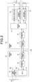
FIG. 2] FIG. 2 is a diagram illustrating configurations of a control unit and a sensor unit; - [
FIG. 3] FIG. 3 is a flowchart of a switch control process; - [
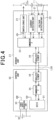
FIG. 4] FIG. 4 is a diagram illustrating configurations of a control unit and a sensor unit according to a second embodiment; - [
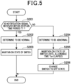
FIG. 5] FIG. 5 is a flowchart of a switch drive process; - [
FIG. 6] FIG. 6 is a diagram illustrating configurations of a control unit and a sensor unit according to a third embodiment; - [
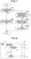
FIG. 7] FIG. 7 is a flowchart of a switch drive instruction process; - [
FIG. 8] FIG. 8 is a diagram illustrating a configuration of a sensor unit according to a fourth embodiment; - [
FIG. 9] FIG. 9 is a timing chart illustrating input-output timings of signals according to the fourth embodiment; - [
FIG. 10] FIG. 10 is a timing chart illustrating input-output timings of signals according to a modification of the fourth embodiment; - [
FIG. 11] FIG. 11 is a diagram illustrating a configuration of a sensor unit according to a fifth embodiment; - [
FIG. 12] FIG. 12 is a diagram illustrating a configuration of a sensor unit according to a modification of the fifth embodiment; and - [
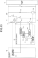
FIG. 13] FIG. 13 is a diagram illustrating a configuration of a vehicular power supply system according to a sixth embodiment. - Hereinafter, embodiments in which a vehicular power supply system is applied to a vehicle (e.g., an electrical vehicle) will be described with reference to the drawings. It is noted that, in the following embodiments, the same or equivalent portions are given the same reference numerals in the drawings, and descriptions of the portions given the same reference numerals are incorporated by reference.
- As illustrated in
FIG. 1 , a vehicularpower supply system 100 includes an assembledbattery 10,sensor units 20 that detect a battery state of the assembledbattery 10, and acontrol unit 30 that is connected to thesensor units 20 and acquires the battery state from thesensor units 20 to perform various types of control based on the battery state. - The assembled
battery 10 has a voltage across terminals of, for example, 100V or higher and is configured by connecting a plurality ofbattery modules 11 in series. Each of thebattery modules 11 is configured by connecting a plurality ofbattery cells 12 in series. As thebattery cell 12, for example, a lithium-ion storage cell or a nickel-hydrogen storage cell may be used. In the present embodiment, thebattery module 11 corresponds to a storage battery. - The assembled
battery 10 is connected to anelectrical load 13 via an electrical path and supplies electrical power to theelectrical load 13. It is noted that theelectrical load 13 includes a rotary electric machine. The assembledbattery 10 supplies electrical power for driving the rotary electric machine. In addition, the assembledbattery 10 may be charged by the rotary electric machine. - Electrical paths L1, L2 connecting the assembled
battery 10 and theelectrical load 13 are provided with a system main relay SMR. In addition, theelectrical load 13 is connected with a capacitor C1 in parallel. - The
sensor units 20 are provided to therespective battery modules 11 and detect (monitor) battery states of therespective battery modules 11. The battery states may include voltage, current, SOC, SOH, internal impedance, battery temperature, and the like. In the description of the present embodiment, voltage and current are detected as the battery states of thebattery modules 11. It is noted that thesensor units 20 may be provided not to therespective battery modules 11 but to respective groups of a plurality ofbattery cells 12. Alternatively, thesensor units 20 may be provided to therespective battery cells 12 or the respective assembledbatteries 10. In addition, thesensor unit 20 may detect a battery state of each of thebattery cells 12 or a battery state of the assembledbattery 10. - Based on
FIG. 2 , thesensor unit 20 will be described in detail. Thesensor unit 20 includes acurrent detection unit 21 that detects a current of thebattery module 11, which is a detection target, and avoltage detection unit 22 that detects a voltage of thebattery module 11, which is a detection target. In addition, on an electrical path connecting thebattery module 11, which is a detection target, and the electrical load 13 (or on an electrical path connecting thebattery modules 11 in series), aswitch 23a is provided which is a switch unit that switches between energization and interruption of energization between thebattery module 11, which is a detection target, and theelectrical load 13. Thesensor unit 20 includes aswitch drive unit 23 that performs on/off-control of theswitch 23a. Theswitch 23a is, for example, a relay switch. Theswitch 23a may be implemented by a pyro fuse. - In addition, the
sensor unit 20 includes acontrol unit 24 that performs various types of control. Thecontrol unit 24 is configured by, for example, a microcomputer including a CPU, a memory, and the like. Thecontrol unit 24 is connected to thecurrent detection unit 21, thevoltage detection unit 22, and theswitch drive unit 23. In addition, thecontrol unit 24 is connected with anMCU 31 of thecontrol unit 30 via a communication path L38,communication IFs elements control unit 30 and performs various processes based on the instructions. For example, if being instructed to detect battery states of thebattery module 11, which is a detection target, by thecontrol unit 30, thecontrol unit 24 receives battery states (current and voltage) from thecurrent detection unit 21 and thevoltage detection unit 22 and outputs the received battery states to thecontrol unit 30. - In addition, if being instructed to interrupt energization of the
battery module 11, which is a detection target, by thecontrol unit 30, thecontrol unit 24 instructs theswitch drive unit 23 to interrupt energization with theswitch 23a. If receiving the instruction to interrupt energization from thecontrol unit 24, theswitch drive unit 23 turns off theswitch 23a to interrupt energization of thebattery module 11. - Next, the
control unit 30 will be described. Thecontrol unit 30 includes an MCU (Micro Controller Unit) 31. TheMCU 31 is a type of microcomputer including a CPU, a memory, and the like. TheMCU 31 receives a request (accelerator position or the like) from the vehicle and performs an instruction to supply electrical power from the assembledbattery 10 to theelectrical load 13 based on the request from the vehicle and the battery states. Specifically, theMCU 31 performs on-control of the system main relay SMR. In addition, when theelectrical load 13 includes a rotary electric machine and the like, theMCU 31 may perform on-control of the system main relay SMR and control charging the assembledbattery 10. - In addition, if any abnormality has occurred in the assembled
battery 10 or the like, theMCU 31 interrupts energization from the assembledbattery 10 to theelectrical load 13. Specifically, theMCU 31 performs off-control of the system main relay SMR and performs an instruction to perform off-control of theswitch 23a. - In addition, the
control unit 30 is connected with anauxiliary power supply 32. Electrical power supplied from theauxiliary power supply 32 is supplied to a powersupply generation unit 33 provided in thecontrol unit 30. The powersupply generation unit 33 converts the electrical power supplied from theauxiliary power supply 32 to drive electrical power for thecontrol unit 30 and supplies the drive electrical power to elements configuring thecontrol unit 30 such as theMCU 31. - As described above, the
MCU 31 of thecontrol unit 30 is configured so as to switch between energization and interruption of energization between the assembled battery 10 (including the battery modules 11) and the electrical load. Hence, if communication with thesensor unit 20 is broken due to some problem, thereby being not capable of acquiring battery states from thesensor unit 20, theMCU 31 cannot perform energization and interruption of energization. Similarly, if an abnormality is caused in theMCU 31, energization and interruption of energization cannot be performed. - If an abnormality is caused in the communication path L38 or the
MCU 31, it is desirable to interrupt energization between the assembledbattery 10 and theelectrical load 13 considering safety. However, in a case of an electrical vehicle, if energization is interrupted between the assembledbattery 10 and theelectrical load 13, power supply to the rotary electric machine serving as a traction unit (vehicle drive source) included in theelectrical load 13 is also interrupted. In this case, the vehicle immediately stops. Hence, the vehicle may stop in such a manner as to obstruct the path of another vehicle on the road, which is a problem. - Meanwhile, even when an abnormality is caused in the communication path L38 or the
MCU 31, no abnormality may be caused in the assembledbattery 10, theelectrical load 13, and the electrical paths L1, L2 therebetween. Hence, if there is no abnormality in the assembledbattery 10 or the like, it is preferable to supply electrical power to theelectrical load 13 for a certain time to allow the vehicle to move in such a degree as not to cause obstruction. Thus, in the present embodiment, thesensor unit 20 is configured as described below to allow the assembledbattery 10 to supply electrical power for a certain time even when communication with thecontrol unit 30 is broken. Hereinafter, the configuration of thesensor unit 20, specifically, a switch control process performed by thecontrol unit 24 will be described based onFIG. 3 . The switch control process is performed by thecontrol unit 24 at predetermined intervals. - The
control unit 24 determines whether the communication path L38 and theMCU 31 are normal (step S101). Specifically, thecontrol unit 24 detects a disconnection of the communication path L38 (including an abnormality of elements provided to the communication path L38) and an abnormality of theMCU 31. The disconnection of the communication path L38 can be detected by various methods such as using a voltage of the communication path L38, using a disconnection detection circuit, or the like. Similarly, an abnormality of theMCU 31 can be detected by various methods, for example, when there is no response from theMCU 31. These abnormality determination methods may be well-known methods. - If the determination result in step S101 is affirmative (if the communication path L38 and the
MCU 31 are normal), thecontrol unit 24 receives a switch control signal from thecontrol unit 30 and controls on/off operation of theswitch 23a based on the received switch control signal (step S102). - It is noted that the
MCU 31 of thecontrol unit 30 acquires switch control information concerning on/off operation of theswitch 23a such as a vehicle request, a battery state, and the like, and outputs the switch control signal for performing an instruction to perform the on/off operation of theswitch 23a. - In contrast, if the determination result in step S101 is negative (if the communication path L38 or the
MCU 31 is abnormal), thecontrol unit 24 acquires battery states (current and voltage) from thecurrent detection unit 21 and the voltage detection unit 22 (step S103). Then, thecontrol unit 24 determines whether thebattery module 11, which is a detection target, is normal based on the acquired battery states (step S104). Specifically, thecontrol unit 24 determines whether the received current and voltage are respectively within predetermined normal value ranges. It is noted that, in the present embodiment, although it is determined whether thebattery module 11 is normal based on current and voltage, the determination may be based on any one of current and voltage. Alternatively, a value other than current and voltage may be received and combined therewith to make the determination, or may make the determination based on the value other than current and voltage. - If the determination result in step S104 is affirmative (if the received current and voltage are within the normal value ranges), the
control unit 24 performs energization maintenance control that makes theswitch drive unit 23 maintain an on state (energization state) of theswitch 23a (step S105). Then, after a predetermined time period has elapsed, thecontrol unit 24 performs processing of step S103 again. - In contrast, if the determination result in step S104 is negative (if the received current and voltage are not within the normal value ranges), the
control unit 24 performs energization interruption control for theswitch drive unit 23 so that theswitch 23a becomes an off state (energization interruption state) (step S106). Specifically, thecontrol unit 24 instructs theswitch drive unit 23 to perform energization interruption with theswitch 23a. On receiving the instruction for energization interruption from thecontrol unit 24, theswitch drive unit 23 turns off theswitch 23a to interrupt energization of thebattery module 11. - The configuration of the present embodiment provides the following significant effects.
- If an abnormality is caused in the
control unit 30 or the communication path L38, thecontrol unit 24 acquires battery states from thecurrent detection unit 21 and thevoltage detection unit 22 and determines whether to maintain energization between thebattery module 11 and theelectrical load 13 based on the acquired battery states. If determining to interrupt energization between thebattery module 11 and theelectrical load 13, thecontrol unit 24 instructs theswitch drive unit 23 to interrupt energization based on the determination. Theswitch drive unit 23 performs off-control of theswitch 23a based on the instruction for the energization interruption. Hence, if an abnormality is caused in thecontrol unit 30 or the communication path L38, power supply from thebattery module 11 is stopped, and the vehicle can be prevented from being immediately stopped. - If an abnormality is caused in the
control unit 30 or the communication path L38, thecontrol unit 24 acquires battery states every time a predetermined time period elapses and determines whether to maintain energization based on the battery states. Hence, after it is determined to maintain energization, if an abnormality is caused in thebattery module 11, energization interruption can be performed to protect thebattery module 11 and the like. -
- In the above first embodiment, after it is determined to maintain energization, if a predetermined saving time has elapsed, the
control unit 24 may perform energization interruption. The saving time is preferably a time period (e.g. about five minutes) during which the own vehicle can be moved to the side of the road at which no obstruction to travel of other vehicles is caused. Hence, thebattery module 11 and the like can be protected more reliably. - In the above first embodiment, a power supply generation unit, which is supplied with electrical power from the
battery module 11 and generates drive electrical power for thesensor unit 20, may be provided to thesensor unit 20. Hence, even if a power line between thesensor unit 20 andcontrol unit 30 is broken, thesensor unit 20 can be driven. - The configuration of the above first embodiment may be modified as the following second embodiment. Hereinafter, in the second embodiment, part different from the configurations described in the above embodiments will be mainly described. In addition, in the second embodiment, as a basic configuration, the vehicular
power supply system 100 of the first embodiment will be exemplified. - Configurations of the
control unit 30 and thesensor unit 20 according to the second embodiment will be described with reference toFIG. 4 . First, the configuration of thecontrol unit 30 will be described. TheMCU 31 of thecontrol unit 30 acquires switch control information concerning on/off operation of theswitch 23a such as a vehicle request, battery states, and the like. Then, theMCU 31 determines whether to turn on or off theswitch 23a based on the switch control information and outputs a switch control signal for instructing thesensor unit 20 to perform on/off operation of theswitch 23a. For example, if the assembledbattery 10 and the like are normal, theMCU 31 outputs a switch control signal for performing instruction to perform on operation of theswitch 23a. In contrast, if an abnormality is caused in the assembledbattery 10 or the like, theMCU 31 outputs a switch control signal for performing instruction to perform off operation of theswitch 23a. - In addition, if the
control unit 30 and the communication path L38 are normal, theMCU 31 outputs a notification signal for making a notification that thecontrol unit 30 and the communication path L38 are normal every time a certain time period T1 has elapsed. The certain time period T1 may be any time period, for example, 5 minutes. - Next, the
sensor unit 20 will be described. As illustrated inFIG. 4 , thesensor units 20 in the second embodiment does not include thecontrol unit 24. Hence, if it is instructed to detect battery states ofbattery module 11, which is a detection target, by thecontrol unit 30, thecurrent detection unit 21 and thevoltage detection unit 22 of the second embodiment directly receive the instruction. In addition, thecurrent detection unit 21 and thevoltage detection unit 22 have a configuration in which if being instructed to detect battery states, thecurrent detection unit 21 and thevoltage detection unit 22 detect battery states (current and voltage) and output the obtained battery states to thecontrol unit 30. Alternatively, thecurrent detection unit 21 and thevoltage detection unit 22 may have a configuration in which thecurrent detection unit 21 and thevoltage detection unit 22 detect battery states (current and voltage) at predetermined intervals and output the obtained battery states to thecontrol unit 30. - In addition, the
switch drive unit 23 has a configuration in which if receiving a switch control signal from thecontrol unit 30, theswitch drive unit 23 changes on/off states of theswitch 23a based on the switch control signal. That is, theswitch drive unit 23 performs drive control of theswitch 23a. - In addition, the
switch drive unit 23 includes a drive latch function and has a configuration in which when receiving a notification signal from thecontrol unit 30 until the certain time period T1 elapses, theswitch drive unit 23 maintains an on state of theswitch 23a. In contrast, theswitch drive unit 23 has a configuration in which when receiving no notification signal from thecontrol unit 30 until the certain time period T1 elapses, theswitch drive unit 23 changes theswitch 23a to an off state. Hereinafter, a switch drive process for implementing this function will be described based onFIG. 5 . The switch drive process is performed by theswitch drive unit 23 at predetermined intervals. - The
switch drive unit 23 determines whether a notification signal is received from thecontrol unit 30 within the certain time period T1 (step S201). If the determination result is affirmative, theswitch drive unit 23 determines that the communication path, theMCU 31, or the like is normal (step S202). Then, thecontrol unit 24 maintains an on state of theswitch 23a (step S203). - In contrast, if the determination result in step S201 is negative, the
switch drive unit 23 determines that an abnormality is caused in the communication path L38, theMCU 31, or the like (step S204). Then, theswitch drive unit 23 maintains an on state of theswitch 23a until a predetermined allowable time Ton elapses (step s205). The allowable time To is a time period (e.g. about five minutes) during which the own vehicle can be moved to the side of the road at which no obstruction to travel of other vehicles is caused, and is preferably as short as possible. After the allowable time Ton has elapsed, theswitch drive unit 23 changes theswitch 23a to an off state to interrupt energization of the battery module 11 (step s206). - Effects of the second embodiment will be described.
- If receiving a notification signal from the
control unit 30 until the certain time period T1 has elapsed, theswitch drive unit 23 determines that the communication path L38 and the like are normal and maintains an on state of theswitch 23a. In contrast, if receiving no notification signal from thecontrol unit 30 until the certain time period T1 has elapsed, theswitch drive unit 23 determines that an abnormality has occurred and changes theswitch 23a to an off state. Thus, without thecontrol unit 24 determining an abnormality, the simple mechanism can maintain energization for a while and thereafter interrupt the energization. -
- In the above second embodiment, the
switch drive unit 23 determines whether to maintain an on state of theswitch 23a based on the battery states detected by thecurrent detection unit 21 and thevoltage detection unit 22. - The configuration of the above first embodiment may be modified as the following third embodiment. Hereinafter, in the third embodiment, part different from the configurations described in the above embodiments will be mainly described. In addition, in the third embodiment, as a basic configuration, the vehicular
power supply system 100 of the first embodiment will be exemplified. - The
sensor unit 20 according to the third embodiment will be described. As illustrated inFIG. 6 , thesensor unit 20 according to the third embodiment does not include thecontrol unit 24. Hence, thecurrent detection unit 21 and thevoltage detection unit 22 according to the third embodiment has a configuration in which if being instructed to detect battery states of thebattery module 11, which is a detection target, by the control unit 30 (or at predetermined intervals), thecurrent detection unit 21 and thevoltage detection unit 22 detect battery states (current and voltage) and output the obtained battery states to thecontrol unit 30. Alternatively, thecurrent detection unit 21 and thevoltage detection unit 22 may have a configuration in which thecurrent detection unit 21 and thevoltage detection unit 22 detect battery states (current and voltage) at predetermined intervals and output the obtained battery states to thecontrol unit 30. - In addition, as in the second embodiment, the
MCU 31 is configured to output a switch control signal. Theswitch drive unit 23 has a configuration in which if receiving a switch control signal from thecontrol unit 30, theswitch drive unit 23 changes on/off states of theswitch 23a based on the switch control signal. - In addition, the
switch drive unit 23 is connected to a sensor side powersupply generation unit 29 provided to thesensor unit 20, and the sensor side powersupply generation unit 29 supplies drive electrical power. The sensor side powersupply generation unit 29 is connected with the powersupply generation unit 33 of thecontrol unit 30, and the powersupply generation unit 33 supplies electrical power. Apower supply switch 37 is provided between the powersupply generation unit 33 and the sensor side powersupply generation unit 29 and is configured to be turned on and off by theMCU 31. That is, theswitch drive unit 23 is configured to maintain an on state of theswitch 23a using electrical power supplied from the powersupply generation unit 33 as drive electrical power. Hence, if thepower supply switch 37 is changed to an off state, and supply of drive electrical power fromcontrol unit 30 is interrupted, the on state of theswitch 23a cannot be maintained, and theswitch 23a is changed to an off state. - The configuration of the
control unit 30 according to the third embodiment will be described. TheMCU 31 of thecontrol unit 30 performs a switch drive instruction process illustrated inFIG. 7 at predetermined intervals. TheMCU 31 determines whether the communication path L38 and thesensor unit 20 are normal (step S301). Specifically, theMCU 31 detects a disconnection of the communication path L38 (including an abnormality of elements provided to the communication path L38) and an abnormality of thesensor unit 20. The method of detecting a disconnection of the communication path L38 is similar to that of the first embodiment. An abnormality of thesensor unit 20 can be detected by various methods, for example, when there is no response from thesensor unit 20, or when an abnormality signal is received from thesensor unit 20. These abnormality determination methods may be well-known methods. - If the determination result is affirmative, that is, if it is normal, the
MCU 31 outputs a switch control signal based on battery states or the like (step S302). Then, theMCU 31 terminates the switch drive instruction process. - In contrast, if the determination result of step S301 is negative, that is, if an abnormality has occurred in the communication path L38 or the
sensor unit 20, it is determined whether to maintain on state of theswitch 23a based on the most recently acquired latest battery state (step S303). - If the determination result of step S303 is affirmative, the
MCU 31 maintains electrical power supply to thesensor unit 20 for the predetermined allowable time Ton (step S304). Hence, since drive electrical power is continuously supplied to theswitch drive unit 23, the on state of theswitch 23a is maintained. It is noted that, in step S304, theMCU 31 may notify an external device such as a host ECU of occurrence of an abnormality. The allowable time Ton is similar to that in the second embodiment. - Then, after the allowable time Ton has elapsed, the
MCU 31 stops supplying drive electrical power to the sensor unit 20 (step S305). Hence, since theswitch drive unit 23 cannot maintain the on state of theswitch 23a, theswitch 23a is changed to an off state. As a result, the energization between thebattery module 11 and theelectrical load 13 is interrupted. - In addition, if the determination result of step S303 is affirmative, the
MCU 31 proceeds to step S305 to stop supplying drive electrical power to thesensor unit 20. Hence, as described above, the energization between thebattery module 11 and theelectrical load 13 is interrupted. - Effects of the third embodiment will be described.
- If an abnormality has occurred in the communication path L38 or the
sensor unit 20, theMCU 31 stops supplying drive electrical power to thesensor unit 20 after the allowable time Ton has elapsed, and causes theswitch 23a to change to an off state. Thus, without thecontrol unit 24 determining an abnormality, the simple mechanism can maintain energization for a while and thereafter interrupt the energization. -
- The above third embodiment may be combined with the above first embodiment or the above second embodiment. Thus, even if an abnormality is caused in any of the
control unit 30 and thesensor unit 20, the vehicle can be prevented from being immediately stopped. - In the above third embodiment, if an abnormality has been caused in the communication path L38 or the like, it is determined whether to maintain on state of the
switch 23a based on the latest battery state. However, without the determination, the on state may be maintained until the allowable time Ton elapses. - The configuration of the above first embodiment may be modified as the following fourth embodiment. Hereinafter, in the third embodiment, part different from the configurations described in the above embodiments will be mainly described. In addition, in the fourth embodiment, as a basic configuration, the vehicular
power supply system 100 of the first embodiment will be exemplified. - As illustrated in
FIG. 8 , thesensor unit 20 according to the fourth embodiment includes a plurality of (two in the present embodiment)current detection unit 21. It is noted that, unlike the first embodiment, thevoltage detection unit 22 may be included or not be included. - The two
current detection units 21 detect currents at different positions. In the fourth embodiment, a firstcurrent detection unit 21a and a secondcurrent detection unit 21b are included. The firstcurrent detection unit 21a detects a current (first current value) at a first position P1 in the vicinity of thebattery module 11 on the electrical path, which is a detection target, of thesensor unit 20. The secondcurrent detection unit 21b is farther from thebattery module 11 than the firstcurrent detection unit 21a and detects a current (second current value) at a second position P2 in the vicinity of theswitch 23a on the electrical path. - The first
current detection unit 21a detects a current at the first position P1. If the value of the current is a predetermined first threshold value or greater, the firstcurrent detection unit 21a outputs a first detection signal indicating this. The secondcurrent detection unit 21b detects a current at the second position P2. If the value of the current is a predetermined second threshold value or greater, the secondcurrent detection unit 21b outputs a second detection signal indicating this. In the second embodiment, the first threshold value and the second threshold value are set to the same value Th. - The first
current detection unit 21a and the secondcurrent detection unit 21b are configures to be connected to an AND circuit AND1 to which the first detection signal and the second detection signal are input. As illustrated inFIG. 9 , if receiving the first detection signal and the second detection signal, the AND circuit AND1 outputs an overcurrent detection signal. - A
switch drive unit 231 in the fourth embodiment is configured to be connected to the AND circuit AND1 and can receive the overcurrent detection signal. Theswitch drive unit 231 is configured to, on receiving the overcurrent detection signal from the AND circuit AND1, change theswitch 23a from an on state to an off state. - Effects of the fourth embodiment will be described.
- Since it is detected whether overcurrents are generated at different two positions (first position P1 and second position P2), noise resistance increases, whereby erroneous detection can be prevented.
-
- In the above fourth embodiment, the first threshold value and the second threshold value are the same value. However, as illustrated in
FIG. 10 , the first threshold value and the second threshold value may be different values Th1 and Th2. Thus, even if noise is generated, malfunctions can be prevented. - In the fourth embodiment, the first
current detection unit 21a and the secondcurrent detection unit 21b may differ in a sampling rate or an internal error count number of times. For example, the firstcurrent detection unit 21a may be configured to output the first detection signal if the number of times that the first threshold value is exceeded (first number of times) is a first internal error count number of times or more. The secondcurrent detection unit 21b may be configured to output the second detection signal if the number of times that the second threshold value is exceeded (second number of times) is a second internal error count number of times or more. In addition, the firstcurrent detection unit 21a may be configured to output the first detection signal if the time period during which the first threshold value is exceeded is a first time period or longer. The secondcurrent detection unit 21b may be configured to output the second detection signal if the time period during which the second threshold value is exceeded is a second time period or longer. Thus, when an overcurrent is generated only for an extremely short time due to influence of noise or the like, erroneous detection can be prevented. - In the fourth embodiment, the first
current detection unit 21a may be a Hall sensor type or a shunt resistance type. Similarly, the secondcurrent detection unit 21b may be a Hall sensor type or a shunt resistance type. Thus, the firstcurrent detection unit 21a and the secondcurrent detection unit 21b can be appropriately changed according to required specifications. - The above fourth embodiment and the modifications thereof may be appropriately combined with the above second embodiment or the above third embodiment.
- The configuration of the above fourth embodiment may be modified as the following fifth embodiment. Hereinafter, in the fifth embodiment, part different from the configurations described in the above embodiments will be mainly described. In addition, in the fifth embodiment, as a basic configuration, the vehicular
power supply system 100 of the fourth embodiment will be exemplified. - As illustrated in
FIG. 11 , in the fifth embodiment, adischarge circuit 51 for quickly discharging charge of the capacitor C1 is provided between thebattery module 11 and theelectrical load 13. Thedischarge circuit 51 is connected with the capacitor C1, thebattery module 11, and theelectrical load 13 in parallel. Thedischarge circuit 51 is configured of a series connection of a resistor R10 and aswitch 23b. Theswitch 23b is normally set so as to be an off state (energization interruption state). - The
sensor unit 20 of the fifth embodiment includes, as in the fourth embodiment, the firstcurrent detection unit 21a, the secondcurrent detection unit 21b, the AND circuit AND1, and theswitch drive unit 231. Thesensor units 20 of the fifth embodiment includes, in addition to the above configuration, a secondswitch drive unit 232. It is noted, in the fifth embodiment, theswitch drive unit 231 is referred to as a firstswitch drive unit 231 as a matter of convenience. - The second
switch drive unit 232 is connected to an output terminal of the AND circuit AND1 via a delay circuit D1. As illustrated inFIG. 11 , if the first detection signal and the second detection signal are input to the AND circuit AND1, and the AND circuit AND1 outputs an overcurrent detection signal, the overcurrent detection signal is input to the secondswitch drive unit 232 by the delay circuit D1 later than to theswitch drive unit 231 by predetermined time. - On receiving the overcurrent detection signal, the second
switch drive unit 232 changes theswitch 23b to an on state. Hence, theswitch 23b becomes an on state after the predetermined time elapses from when the firstswitch drive unit 231 changes theswitch 23a to an off state. Thus, charge of the capacitor C1 is discharged by thedischarge circuit 51. - Effects of the fifth embodiment will be described.
- After the predetermined time has elapsed from when energization of the
battery module 11 is interrupted, the secondswitch drive unit 232 changes theswitch 23b to an on state to cause thedischarge circuit 51 to discharge charge of the capacitor C1. Thus, the charge of the capacitor C1 can be quickly discharged. -
- In the above fifth embodiment, the second
switch drive unit 232 is configured to turn on theswitch 23b after the predetermined time has elapsed from when energization of thebattery module 11 is interrupted. As another example, as illustrated inFIG. 12 , a connection determination circuit 52 may be included which determines that theswitch 23a has been changed to an off state. In addition, the secondswitch drive unit 232 may be configured to change theswitch 23b to an on state if it is determined by the connection determination circuit 52 that theswitch 23a has been changed to an off state. - The above fifth embodiment and the modifications thereof may be appropriately combined with the above second embodiment or the above third embodiment.
- The configuration of the above fifth embodiment may be modified as the following sixth embodiment. Hereinafter, in the fifth embodiment, part different from the configurations described in the above embodiments will be mainly described. In addition, in the sixth embodiment, as a basic configuration, the vehicular
power supply system 100 of the fifth embodiment will be exemplified. - As illustrated in
FIG. 13 , the assembledbattery 10 in the sixth embodiment is configured by afirst battery module 61 and asecond battery module 62. In addition, thefirst battery module 61 and thesecond battery module 62 are configured to be able to be changed between a serial connection and a parallel connection. - Specifically, the
first battery module 61 and thesecond battery module 62 are connected in series via a switch F1. A first connection changing switch S1 is connected to thefirst battery module 61 in parallel. The first connection changing switch S1 has one end connected to a positive electrode side electrical path L1 and the other end connected between the switch F1 and thesecond battery module 62. Similarly, a second connection changing switch S2 is connected to thesecond battery module 62 in parallel. The second connection changing switch S2 has one end connected to a negative electrode side electrical path L2 and the other end connected between the switch F1 and thefirst battery module 61. - When the
first battery module 61 and thesecond battery module 62 are connected in series, the first connection changing switch S1 and the second connection changing switch S2 are changed to off states. When thefirst battery module 61 and thesecond battery module 62 are connected in parallel, the first connection changing switch S1 and the second connection changing switch S2 are changed to on states. - The first connection changing switch S1 and the second connection changing switch S2 may be subjected to on/off-control by the
control unit 30 or thesensor unit 20 or may be subjected to on/off-control by the host ECU or the like. It is noted that when electrical power is supplied from the assembledbattery 10 to theelectrical load 13, thefirst battery module 61 and thesecond battery module 62 are connected in series. In contrast, when electrical power is supplied from the rotary electric machine included in theelectrical load 13 to the assembled battery 10 (i.e., when the assembledbattery 10 is charged), thefirst battery module 61 and thesecond battery module 62 are connected in parallel. - In addition, in the sixth embodiment, the
sensor unit 20 is provided with a low-voltage substrate 63 whose drive electrical power has a low voltage and a high-voltage substrate 64 whose drive electrical power is higher than that of the low-voltage substrate 63. The low-voltage substrate 63 is provided with the firstcurrent detection unit 21a. The high-voltage substrate 64 is provided with the secondcurrent detection unit 21b. - In the sixth embodiment, the first
current detection unit 21a detects a current flowing through a first point P11 located on the negative electrode terminal side of thefirst battery module 61 with respect to a connection point of the second connection changing switch S2 on the electrical path between thefirst battery module 61 and thesecond battery module 62. The first point P11 is a point at which a current from thefirst battery module 61 can be detected in any connection manner. - In addition, in the sixth embodiment, the second
current detection unit 21b detects a current flowing through a second point P12 located on the positive electrode terminal side of thesecond battery module 62 with respect to a connection point of the first connection changing switch S1 on the electrical path between thefirst battery module 61 and thesecond battery module 62. The second point P12 is a point at which a current from thesecond battery module 62 can be detected in any connection manner. - In the sixth embodiment, the first
current detection unit 21a and the secondcurrent detection unit 21b are connected to anabnormality determination circuit 53. Theabnormality determination circuit 53 is provided to the high-voltage substrate 64. Theabnormality determination circuit 53 is configured to receive connection information concerning whether thefirst battery module 61 and thesecond battery module 62 are connected in series. - If the
first battery module 61 and thesecond battery module 62 are connected in series, when receiving the first detection signal and the second detection signal, theabnormality determination circuit 53 outputs an overcurrent detection signal. In contrast, if thefirst battery module 61 and thesecond battery module 62 are connected in parallel (not in series), when receiving any of the first detection signal and the second detection signal, theabnormality determination circuit 53 outputs an overcurrent detection signal. - The
sensor unit 20 of the sixth embodiment includes, as in the fifth embodiment, the firstswitch drive unit 231 and the secondswitch drive unit 232. - The first
switch drive unit 231 in the sixth embodiment is connected to theabnormality determination circuit 53 and is configured to be able to receive the overcurrent detection signal. The firstswitch drive unit 231 is configures to, on receiving the overcurrent detection signal from theabnormality determination circuit 53, change theswitch 23a from an on state to an off state. - The second
switch drive unit 232 is connected to an output terminal of theabnormality determination circuit 53 via the delay circuit D1. As in the fifth embodiment, if the overcurrent detection signal is output from theabnormality determination circuit 53, the overcurrent detection signal is input to the secondswitch drive unit 232 by the delay circuit D1 later than to the firstswitch drive unit 231 by predetermined time. - On receiving the overcurrent detection signal, the second
switch drive unit 232 changes theswitch 23b to an on state. Hence, theswitch 23b becomes an on state after the predetermined time elapses from when the firstswitch drive unit 231 changes theswitch 23b to an off state. Thus, charge of the capacitor C1 is discharged by thedischarge circuit 51. - The above sixth embodiment has, in addition to the effects of the above fifth embodiment, the following effects.
when electrical power is supplied from the assembledbattery 10 to theelectrical load 13, thefirst battery module 61 and thesecond battery module 62 are connected in series. In contrast, when electrical power is supplied from the rotary electric machine included in theelectrical load 13 to the assembled battery 10 (i.e., when the assembledbattery 10 is charged), thefirst battery module 61 and thesecond battery module 62 are connected in parallel. Hence, the charging voltage can be lowered, while the electrical power supplied to theelectrical load 13 becomes a high voltage. Thus, the configuration for increasing the charging voltage supplied from the rotary electric machine can be omitted or simplified. - If the
first battery module 61 and thesecond battery module 62 are connected in series, when receiving the first detection signal and the second detection signal, theabnormality determination circuit 53 outputs an overcurrent detection signal. In contrast, if thefirst battery module 61 and thesecond battery module 62 are connected in parallel, when receiving any of the first detection signal and the second detection signal, theabnormality determination circuit 53 outputs an overcurrent detection signal. Hence, depending on the connection manner, overcurrent can be appropriately detected. It is noted that when charged is performed, since energization is interrupted between theelectrical load 13 other than the rotary electric machine and the assembledbattery 10. Hence, it is expected that noise to the assembledbattery 10 decreases. Thus, when thefirst battery module 61 and thesecond battery module 62 are connected in parallel, an overcurrent can be detected appropriately. -
- The above embodiment may be configured to output an overcurrent detection signal in any communication state when the first detection signal and the second detection signal are output.
- The above sixth embodiment and the modifications thereof may be appropriately combined with the above second embodiment or the above third embodiment.
- • In the above sixth embodiment, the
sensor unit 20 is provided with the low-voltage substrate 63 and the high-voltage substrate 64 separately. However, the low-voltage substrate 63 and the high-voltage substrate 64 may not be separated. - In the above sixth embodiment, the
first battery module 61 and thesecond battery module 62 may be configured to be connected in parallel when an abnormality has occurred. In addition, thefirst battery module 61 and thesecond battery module 62 may be configured to be connected in series if it is determined that no overcurrent has been generated. - In the above sixth embodiment, the first point P11 may be changed to any point in any connection manner if a current from the
first battery module 61 can be detected at the point. Similarly, the second point P12 may be changed to any point in any connection manner if a current from thesecond battery module 62 can be detected at the point. - Hereinafter, characteristic configurations extracted from the embodiments described above will be described.
- A vehicular power supply system (100) including a sensor unit (20) that detects a battery state of a storage battery (11) that is capable of supplying electrical power to an electrical load (13), and a control unit (30) that receives the battery state from the sensor unit via a communication path (L38) and performs instruction to perform energization and interruption of the energization between the storage battery and the electrical load based on the received battery state, wherein
the sensor unit includes: - a detection unit (21) that detects the battery state of the storage battery;
- a switch drive unit (23) that performs drive control of a switch unit (23a) provided between the storage battery and the electrical load; and
- a control unit (24) that controls the switch drive unit,
- the control unit controls the switch drive unit based on the instruction from the control unit to switch between the energization and interruption of the energization between the storage battery and the electrical load, and
- if determining an abnormality in the control unit or the communication path, the control unit determines whether to maintain the energization between the storage battery and the electrical load based on the battery state detected by the detection unit and controls the switch drive unit based on the determination to switch between the energization and interruption of the energization between the storage battery and the electrical load.
- A vehicular power supply system (100) including a sensor unit (20) that detects a battery state of a storage battery (11) that is capable of supplying electrical power to an electrical load (13), and a control unit (30) that receives the battery state from the sensor unit via a communication path (L38) and performs instruction to perform energization and interruption of the energization between the storage battery and the electrical load based on the received battery state, wherein
the sensor unit includes: - a detection unit (21) that detects the battery state of the storage battery; and
- a switch drive unit (23) that performs drive control of a switch unit (23a) provided between the storage battery and the electrical load based on the instruction of the control unit to switch between the energization and the interruption of the energization between the storage battery and the electrical load,
- the control unit is configured to, in a normal state, output a notification signal indicating the normal state every time a certain time period has elapsed, and
- if receiving the notification signal from the control unit every time the certain time period has elapsed, the switch drive unit maintains the energization between the storage battery and the electrical load, and if not receiving the notification signal from the control unit every time the certain time period has elapsed, the switch drive unit performs drive control of the switch unit to interrupt the energization between the storage battery and the electrical load after a predetermined allowable time has elapsed.
- The vehicular power supply system according to
configuration 1 or 2, wherein - the control unit includes a power supply generation unit (33) that converts electrical power supplied from an auxiliary power supply to generate drive electrical power,
- the power supply generation unit is configured to supply the drive electrical power to the switch drive unit, and
- if communication from the sensor unit is interrupted or if a notification of occurrence of an abnormality is received from the sensor unit, the control unit determines whether to maintain the energization between the storage battery and the electrical load for a predetermined time period based on the most recently received battery state and maintains or stops supply of the drive electrical power based on the determination.
- The vehicular power supply system according to any one of
configurations 1 to 3, wherein - the detection unit includes a first current detection unit (21a) that detects a first current value at a first point (P1) on an electrical path between the storage battery and the electrical load and a second current detection unit (21b) that detects a second current value at a second point (P2) different from the first point on the electrical path, and
- if the first current value is a first threshold value or greater and the second current value is a second threshold value or greater, the switch drive unit performs drive control of the switch unit to interrupt the energization between the storage battery and the electrical load.
- The vehicular power supply system according to configuration 4, wherein
if the number of times the first current value is the first threshold value or more is a predetermined first number of times or more and if the number of times the second current value is the second threshold value or more is a second number of times, which is different from the first number of times, or more, the switch drive unit performs drive control of the switch unit to interrupt the energization between the storage battery and the electrical load. - The vehicular power supply system according to configuration 4 or 5, wherein
- the storage battery is an assembled battery (10) configured by a first battery module (61) and a second battery module (62),
- the first battery module and the second battery module are configured to be capable of being changed between a series connection and a parallel connection,
- the first point is a point (P11) at which a current from the first battery module is capable of being detected in any connection manner,
- the second point is a point (P12) at which a current from the second battery module is capable of being detected in any connection manner,
- when the first battery module and the second battery module are connected in series, if the first current value is the first threshold value or greater and the second current value is the second threshold value or greater, the switch drive unit performs drive control of the switch unit to interrupt the energization between the storage battery and the electrical load, and
- when the first battery module and the second battery module are connected in parallel, if the first current value is the first threshold value or greater or the second current value is the second threshold value or greater, the switch drive unit performs drive control of the switch unit to interrupt the energization between the storage battery and the electrical load, and
- The vehicular power supply system according to any one of
configurations 1 to 6, further including a discharge circuit (51) that causes a capacitor connected to the electrical load in parallel to discharge charge after the energization is interrupted by the switch drive unit. - The present disclosure has so far been described based on embodiments. However, the present disclosure should not be construed as being limited to these embodiments or the structures. The present disclosure should encompass various modifications, or modifications within the range of equivalence. In addition, various combinations and modes, as well as other combinations and modes, including those which include one or more additional elements, or those which include fewer elements should be construed as being within the scope and spirit of the present disclosure.
Claims (7)
- A vehicular power supply system (100) including a sensor unit (20) that detects a battery state of a storage battery (11) that is capable of supplying electrical power to an electrical load (13), and a control unit (30) that receives the battery state from the sensor unit via a communication path (L38) and performs instruction to perform energization and interruption of the energization between the storage battery and the electrical load based on the received battery state, wherein
the sensor unit includes:a detection unit (21) that detects the battery state of the storage battery;a switch drive unit (23) that performs drive control of a switch unit (23a) provided between the storage battery and the electrical load; anda control unit (24) that controls the switch drive unit,the control unit controls the switch drive unit based on the instruction from the control unit to switch between the energization and interruption of the energization between the storage battery and the electrical load, andif determining an abnormality in the control unit or the communication path, the control unit determines whether to maintain the energization between the storage battery and the electrical load based on the battery state detected by the detection unit and controls the switch drive unit based on the determination to switch between the energization and interruption of the energization between the storage battery and the electrical load. - A vehicular power supply system (100) including a sensor unit (20) that detects a battery state of a storage battery (11) that is capable of supplying electrical power to an electrical load (13), and a control unit (30) that receives the battery state from the sensor unit via a communication path (L38) and performs instruction to perform energization and interruption of the energization between the storage battery and the electrical load based on the received battery state, wherein
the sensor unit includes:a detection unit (21) that detects the battery state of the storage battery; anda switch drive unit (23) that performs drive control of a switch unit (23a) provided between the storage battery and the electrical load based on the instruction of the control unit to switch between the energization and the interruption of the energization between the storage battery and the electrical load,the control unit is configured to, in a normal state, output a notification signal indicating the normal state every time a certain time period has elapsed, andif receiving the notification signal from the control unit every time the certain time period has elapsed, the switch drive unit maintains the energization between the storage battery and the electrical load, and if not receiving the notification signal from the control unit every time the certain time period has elapsed, the switch drive unit performs drive control of the switch unit to interrupt the energization between the storage battery and the electrical load after a predetermined allowable time has elapsed. - The vehicular power supply system according to claim 1 or 2, whereinthe control unit includes a power supply generation unit (33) that converts electrical power supplied from an auxiliary power supply to generate drive electrical power,the power supply generation unit is configured to supply the drive electrical power to the switch drive unit, andif communication from the sensor unit is interrupted or if a notification of occurrence of an abnormality is received from the sensor unit, the control unit determines whether to maintain the energization between the storage battery and the electrical load for a predetermined time period based on the most recently received battery state and maintains or stops supply of the drive electrical power based on the determination.
- The vehicular power supply system according to claim 1 or 2, whereinthe detection unit includes a first current detection unit (21a) that detects a first current value at a first point (P1) on an electrical path between the storage battery and the electrical load and a second current detection unit (21b) that detects a second current value at a second point (P2) different from the first point on the electrical path, andif the first current value is a first threshold value or greater and the second current value is a second threshold value or greater, the switch drive unit performs drive control of the switch unit to interrupt the energization between the storage battery and the electrical load.
- The vehicular power supply system according to claim 4, wherein
if the number of times the first current value is the first threshold value or more is a predetermined first number of times or more and if the number of times the second current value is the second threshold value or more is a second number of times, which is different from the first number of times, or more, the switch drive unit performs drive control of the switch unit to interrupt the energization between the storage battery and the electrical load. - The vehicular power supply system according to claim 4, whereinthe storage battery is an assembled battery (10) configured by a first battery module (61) and a second battery module (62),the first battery module and the second battery module are configured to be capable of being changed between a series connection and a parallel connection,the first point is a point (P11) at which a current from the first battery module is capable of being detected in any connection manner,the second point is a point (P12) at which a current from the second battery module is capable of being detected in any connection manner,when the first battery module and the second battery module are connected in series, if the first current value is the first threshold value or greater and the second current value is the second threshold value or greater, the switch drive unit performs drive control of the switch unit to interrupt the energization between the storage battery and the electrical load, andwhen the first battery module and the second battery module are connected in parallel, if the first current value is the first threshold value or greater or the second current value is the second threshold value or greater, the switch drive unit performs drive control of the switch unit to interrupt the energization between the storage battery and the electrical load.
- The vehicular power supply system according to claim 1, further comprising a discharge circuit (51) that causes a capacitor connected to the electrical load in parallel to discharge charge after the energization is interrupted by the switch drive unit.
Applications Claiming Priority (2)
| Application Number | Priority Date | Filing Date | Title |
|---|---|---|---|
| JP2021136438A JP7416027B2 (en) | 2021-08-24 | 2021-08-24 | Vehicle power system |
| PCT/JP2022/030778 WO2023026874A1 (en) | 2021-08-24 | 2022-08-12 | Power supply system for vehicle |
Publications (2)
| Publication Number | Publication Date |
|---|---|
| EP4393777A1 true EP4393777A1 (en) | 2024-07-03 |
| EP4393777A4 EP4393777A4 (en) | 2025-02-19 |
Family
ID=85323217
Family Applications (1)
| Application Number | Title | Priority Date | Filing Date |
|---|---|---|---|
| EP22861163.8A Pending EP4393777A4 (en) | 2021-08-24 | 2022-08-12 | POWER SUPPLY SYSTEM FOR A VEHICLE |
Country Status (5)
| Country | Link |
|---|---|
| US (1) | US12391121B2 (en) |
| EP (1) | EP4393777A4 (en) |
| JP (1) | JP7416027B2 (en) |
| CN (1) | CN117858822A (en) |
| WO (1) | WO2023026874A1 (en) |
Families Citing this family (3)
| Publication number | Priority date | Publication date | Assignee | Title |
|---|---|---|---|---|
| US12246665B2 (en) | 2023-05-22 | 2025-03-11 | Joseph & Roberts, LLC | System and method for powering a vehicle accessory |
| DE102024118959A1 (en) * | 2024-07-04 | 2026-01-08 | Bayerische Motoren Werke Aktiengesellschaft | High-voltage system with active discharge of X-capacitances |
| EP4714714A1 (en) * | 2024-09-19 | 2026-03-25 | Volvo Truck Corporation | Method for controlling an energy system in a vehicle |
Family Cites Families (14)
| Publication number | Priority date | Publication date | Assignee | Title |
|---|---|---|---|---|
| JP2008195255A (en) * | 2007-02-14 | 2008-08-28 | Toyota Motor Corp | Vehicle power system |
| JP2008312396A (en) * | 2007-06-15 | 2008-12-25 | Yazaki Corp | Vehicle power supply system |
| JP2012093343A (en) * | 2010-09-30 | 2012-05-17 | Gs Yuasa Corp | Failure detection device and failure detection method |
| JP5673658B2 (en) * | 2012-12-03 | 2015-02-18 | トヨタ自動車株式会社 | Power storage system |
| US9889880B2 (en) * | 2014-03-11 | 2018-02-13 | Nsk Ltd. | Motor control device, electric power steering device using same, and vehicle |
| WO2015156371A1 (en) * | 2014-04-10 | 2015-10-15 | 株式会社デンソー | Control device and ignition device |
| JP6603085B2 (en) * | 2015-09-04 | 2019-11-06 | 株式会社エンビジョンAescジャパン | Vehicle power supply device and vehicle control device |
| JP6704895B2 (en) | 2017-12-20 | 2020-06-03 | 株式会社Subaru | Electric vehicle power supply system |
| JP7041567B2 (en) * | 2018-03-27 | 2022-03-24 | 株式会社Subaru | Vehicle power supply |
| JP7129008B2 (en) * | 2018-11-29 | 2022-09-01 | トヨタ自動車株式会社 | power system |
| JP7103199B2 (en) * | 2018-12-17 | 2022-07-20 | 株式会社デンソー | Precharge controller |
| JP7251222B2 (en) * | 2019-03-11 | 2023-04-04 | 株式会社デンソー | Motor control device and motor control method |
| JP7055777B2 (en) | 2019-07-12 | 2022-04-18 | 矢崎総業株式会社 | Detection device |
| JP7543119B2 (en) | 2020-02-25 | 2024-09-02 | 芝浦メカトロニクス株式会社 | Substrate Processing Equipment |
-
2021
- 2021-08-24 JP JP2021136438A patent/JP7416027B2/en active Active
-
2022
- 2022-08-12 WO PCT/JP2022/030778 patent/WO2023026874A1/en not_active Ceased
- 2022-08-12 EP EP22861163.8A patent/EP4393777A4/en active Pending
- 2022-08-12 CN CN202280057832.XA patent/CN117858822A/en active Pending
-
2024
- 2024-02-26 US US18/586,737 patent/US12391121B2/en active Active
Also Published As
| Publication number | Publication date |
|---|---|
| JP2023030995A (en) | 2023-03-08 |
| US20240190252A1 (en) | 2024-06-13 |
| WO2023026874A1 (en) | 2023-03-02 |
| EP4393777A4 (en) | 2025-02-19 |
| CN117858822A (en) | 2024-04-09 |
| US12391121B2 (en) | 2025-08-19 |
| JP7416027B2 (en) | 2024-01-17 |
Similar Documents
| Publication | Publication Date | Title |
|---|---|---|
| KR102329913B1 (en) | Battery management system for monitoring and regulating the operation of a battery and battery system having such a battery management system | |
| KR101234059B1 (en) | Apparatus and Method for diagnosis of cell balancing unit | |
| US12391121B2 (en) | Vehicular power supply system | |
| EP2879900B1 (en) | Electrical storage system | |
| US10090683B2 (en) | Battery management system for controlling an energy storage assembly and method for charging and discharging an energy storage assembly | |
| EP2485364B1 (en) | Control device for an assembled battery | |
| US9941712B2 (en) | Electrical storage system | |
| CN105612082B (en) | Method and device for the voltage-controlled automatic disconnection of an electronic component or a battery cell | |
| US10096992B2 (en) | Electrical storage system | |
| US9840157B2 (en) | Battery management system and battery system | |
| US11418042B2 (en) | Battery management unit | |
| JP2013092397A (en) | Battery monitoring device | |
| EP3349327B1 (en) | Battery management device | |
| CN103998946A (en) | Monitor system and vehicle | |
| KR20180115239A (en) | Safety monitoring unit | |
| CN106688156B (en) | Vehicle battery system | |
| US20250330030A1 (en) | Electricity storage apparatus and method of interrupting electric current | |
| EP4068547A1 (en) | Vehicle-mounted battery system | |
| EP4495611A1 (en) | Power source device | |
| CN115241954A (en) | A vehicle intelligent power distribution management system and method | |
| US20210273469A1 (en) | Method for operating a battery module | |
| JP2020022366A (en) | vehicle | |
| US20250192255A1 (en) | Battery system | |
| EP4678480A1 (en) | Power distribution device and wire-disconnect determination method | |
| JP7613946B2 (en) | Power System |
Legal Events
| Date | Code | Title | Description |
|---|---|---|---|
| STAA | Information on the status of an ep patent application or granted ep patent |
Free format text: STATUS: THE INTERNATIONAL PUBLICATION HAS BEEN MADE |
|
| PUAI | Public reference made under article 153(3) epc to a published international application that has entered the european phase |
Free format text: ORIGINAL CODE: 0009012 |
|
| STAA | Information on the status of an ep patent application or granted ep patent |
Free format text: STATUS: REQUEST FOR EXAMINATION WAS MADE |
|
| 17P | Request for examination filed |
Effective date: 20240307 |
|
| AK | Designated contracting states |
Kind code of ref document: A1 Designated state(s): AL AT BE BG CH CY CZ DE DK EE ES FI FR GB GR HR HU IE IS IT LI LT LU LV MC MK MT NL NO PL PT RO RS SE SI SK SM TR |
|
| DAV | Request for validation of the european patent (deleted) | ||
| DAX | Request for extension of the european patent (deleted) | ||
| REG | Reference to a national code |
Ref country code: DE Ref legal event code: R079 Free format text: PREVIOUS MAIN CLASS: B60R0016020000 Ipc: B60L0003000000 |
|
| STAA | Information on the status of an ep patent application or granted ep patent |
Free format text: STATUS: EXAMINATION IS IN PROGRESS |
|
| A4 | Supplementary search report drawn up and despatched |
Effective date: 20250116 |
|
| RIC1 | Information provided on ipc code assigned before grant |
Ipc: H02J 7/00 20060101ALI20250110BHEP Ipc: H02H 7/20 20060101ALI20250110BHEP Ipc: H02H 7/18 20060101ALI20250110BHEP Ipc: B60R 16/02 20060101ALI20250110BHEP Ipc: B60L 58/12 20190101ALI20250110BHEP Ipc: B60L 3/04 20060101ALI20250110BHEP Ipc: B60L 3/00 20190101AFI20250110BHEP |
|
| 17Q | First examination report despatched |
Effective date: 20250217 |