EP4393776A1 - Display apparatus, vehicle, and control method for vehicle - Google Patents
Display apparatus, vehicle, and control method for vehicle Download PDFInfo
- Publication number
- EP4393776A1 EP4393776A1 EP22914342.5A EP22914342A EP4393776A1 EP 4393776 A1 EP4393776 A1 EP 4393776A1 EP 22914342 A EP22914342 A EP 22914342A EP 4393776 A1 EP4393776 A1 EP 4393776A1
- Authority
- EP
- European Patent Office
- Prior art keywords
- display device
- display
- preset
- light
- optical waveguide
- Prior art date
- Legal status (The legal status is an assumption and is not a legal conclusion. Google has not performed a legal analysis and makes no representation as to the accuracy of the status listed.)
- Pending
Links
Images


Classifications
-
- G—PHYSICS
- G02—OPTICS
- G02B—OPTICAL ELEMENTS, SYSTEMS OR APPARATUS
- G02B27/00—Optical systems or apparatus not provided for by any of the groups G02B1/00 - G02B26/00, G02B30/00
- G02B27/01—Head-up displays
- G02B27/017—Head mounted
- G02B27/0172—Head mounted characterised by optical features
-
- B—PERFORMING OPERATIONS; TRANSPORTING
- B60—VEHICLES IN GENERAL
- B60K—ARRANGEMENT OR MOUNTING OF PROPULSION UNITS OR OF TRANSMISSIONS IN VEHICLES; ARRANGEMENT OR MOUNTING OF PLURAL DIVERSE PRIME-MOVERS IN VEHICLES; AUXILIARY DRIVES FOR VEHICLES; INSTRUMENTATION OR DASHBOARDS FOR VEHICLES; ARRANGEMENTS IN CONNECTION WITH COOLING, AIR INTAKE, GAS EXHAUST OR FUEL SUPPLY OF PROPULSION UNITS IN VEHICLES
- B60K35/00—Instruments specially adapted for vehicles; Arrangement of instruments in or on vehicles
- B60K35/20—Output arrangements, i.e. from vehicle to user, associated with vehicle functions or specially adapted therefor
- B60K35/21—Output arrangements, i.e. from vehicle to user, associated with vehicle functions or specially adapted therefor using visual output, e.g. blinking lights or matrix displays
- B60K35/22—Display screens
-
- B—PERFORMING OPERATIONS; TRANSPORTING
- B60—VEHICLES IN GENERAL
- B60K—ARRANGEMENT OR MOUNTING OF PROPULSION UNITS OR OF TRANSMISSIONS IN VEHICLES; ARRANGEMENT OR MOUNTING OF PLURAL DIVERSE PRIME-MOVERS IN VEHICLES; AUXILIARY DRIVES FOR VEHICLES; INSTRUMENTATION OR DASHBOARDS FOR VEHICLES; ARRANGEMENTS IN CONNECTION WITH COOLING, AIR INTAKE, GAS EXHAUST OR FUEL SUPPLY OF PROPULSION UNITS IN VEHICLES
- B60K35/00—Instruments specially adapted for vehicles; Arrangement of instruments in or on vehicles
- B60K35/20—Output arrangements, i.e. from vehicle to user, associated with vehicle functions or specially adapted therefor
- B60K35/21—Output arrangements, i.e. from vehicle to user, associated with vehicle functions or specially adapted therefor using visual output, e.g. blinking lights or matrix displays
- B60K35/23—Head-up displays [HUD]
-
- B—PERFORMING OPERATIONS; TRANSPORTING
- B60—VEHICLES IN GENERAL
- B60K—ARRANGEMENT OR MOUNTING OF PROPULSION UNITS OR OF TRANSMISSIONS IN VEHICLES; ARRANGEMENT OR MOUNTING OF PLURAL DIVERSE PRIME-MOVERS IN VEHICLES; AUXILIARY DRIVES FOR VEHICLES; INSTRUMENTATION OR DASHBOARDS FOR VEHICLES; ARRANGEMENTS IN CONNECTION WITH COOLING, AIR INTAKE, GAS EXHAUST OR FUEL SUPPLY OF PROPULSION UNITS IN VEHICLES
- B60K35/00—Instruments specially adapted for vehicles; Arrangement of instruments in or on vehicles
- B60K35/50—Instruments characterised by their means of attachment to or integration in the vehicle
-
- B—PERFORMING OPERATIONS; TRANSPORTING
- B60—VEHICLES IN GENERAL
- B60K—ARRANGEMENT OR MOUNTING OF PROPULSION UNITS OR OF TRANSMISSIONS IN VEHICLES; ARRANGEMENT OR MOUNTING OF PLURAL DIVERSE PRIME-MOVERS IN VEHICLES; AUXILIARY DRIVES FOR VEHICLES; INSTRUMENTATION OR DASHBOARDS FOR VEHICLES; ARRANGEMENTS IN CONNECTION WITH COOLING, AIR INTAKE, GAS EXHAUST OR FUEL SUPPLY OF PROPULSION UNITS IN VEHICLES
- B60K35/00—Instruments specially adapted for vehicles; Arrangement of instruments in or on vehicles
- B60K35/65—Instruments specially adapted for specific vehicle types or users, e.g. for left- or right-hand drive
- B60K35/656—Instruments specially adapted for specific vehicle types or users, e.g. for left- or right-hand drive the user being a passenger
-
- G—PHYSICS
- G02—OPTICS
- G02B—OPTICAL ELEMENTS, SYSTEMS OR APPARATUS
- G02B27/00—Optical systems or apparatus not provided for by any of the groups G02B1/00 - G02B26/00, G02B30/00
- G02B27/01—Head-up displays
- G02B27/0101—Head-up displays characterised by optical features
-
- G—PHYSICS
- G02—OPTICS
- G02B—OPTICAL ELEMENTS, SYSTEMS OR APPARATUS
- G02B27/00—Optical systems or apparatus not provided for by any of the groups G02B1/00 - G02B26/00, G02B30/00
- G02B27/01—Head-up displays
- G02B27/0101—Head-up displays characterised by optical features
- G02B27/0103—Head-up displays characterised by optical features comprising holographic elements
-
- G—PHYSICS
- G02—OPTICS
- G02B—OPTICAL ELEMENTS, SYSTEMS OR APPARATUS
- G02B6/00—Light guides; Structural details of arrangements comprising light guides and other optical elements, e.g. couplings
- G02B6/0001—Light guides; Structural details of arrangements comprising light guides and other optical elements, e.g. couplings specially adapted for lighting devices or systems
- G02B6/0011—Light guides; Structural details of arrangements comprising light guides and other optical elements, e.g. couplings specially adapted for lighting devices or systems the light guides being planar or of plate-like form
- G02B6/0013—Means for improving the coupling-in of light from the light source into the light guide
- G02B6/0023—Means for improving the coupling-in of light from the light source into the light guide provided by one optical element, or plurality thereof, placed between the light guide and the light source, or around the light source
- G02B6/0026—Wavelength selective element, sheet or layer, e.g. filter or grating
-
- G—PHYSICS
- G02—OPTICS
- G02B—OPTICAL ELEMENTS, SYSTEMS OR APPARATUS
- G02B6/00—Light guides; Structural details of arrangements comprising light guides and other optical elements, e.g. couplings
- G02B6/0001—Light guides; Structural details of arrangements comprising light guides and other optical elements, e.g. couplings specially adapted for lighting devices or systems
- G02B6/0011—Light guides; Structural details of arrangements comprising light guides and other optical elements, e.g. couplings specially adapted for lighting devices or systems the light guides being planar or of plate-like form
- G02B6/0033—Means for improving the coupling-out of light from the light guide
- G02B6/005—Means for improving the coupling-out of light from the light guide provided by one optical element, or plurality thereof, placed on the light output side of the light guide
-
- G—PHYSICS
- G02—OPTICS
- G02B—OPTICAL ELEMENTS, SYSTEMS OR APPARATUS
- G02B6/00—Light guides; Structural details of arrangements comprising light guides and other optical elements, e.g. couplings
- G02B6/10—Light guides; Structural details of arrangements comprising light guides and other optical elements, e.g. couplings of the optical waveguide type
- G02B6/12—Light guides; Structural details of arrangements comprising light guides and other optical elements, e.g. couplings of the optical waveguide type of the integrated circuit kind
- G02B6/122—Basic optical elements, e.g. light-guiding paths
-
- B—PERFORMING OPERATIONS; TRANSPORTING
- B60—VEHICLES IN GENERAL
- B60K—ARRANGEMENT OR MOUNTING OF PROPULSION UNITS OR OF TRANSMISSIONS IN VEHICLES; ARRANGEMENT OR MOUNTING OF PLURAL DIVERSE PRIME-MOVERS IN VEHICLES; AUXILIARY DRIVES FOR VEHICLES; INSTRUMENTATION OR DASHBOARDS FOR VEHICLES; ARRANGEMENTS IN CONNECTION WITH COOLING, AIR INTAKE, GAS EXHAUST OR FUEL SUPPLY OF PROPULSION UNITS IN VEHICLES
- B60K2360/00—Indexing scheme associated with groups B60K35/00 or B60K37/00 relating to details of instruments or dashboards
- B60K2360/149—Instrument input by detecting viewing direction not otherwise provided for
-
- B—PERFORMING OPERATIONS; TRANSPORTING
- B60—VEHICLES IN GENERAL
- B60K—ARRANGEMENT OR MOUNTING OF PROPULSION UNITS OR OF TRANSMISSIONS IN VEHICLES; ARRANGEMENT OR MOUNTING OF PLURAL DIVERSE PRIME-MOVERS IN VEHICLES; AUXILIARY DRIVES FOR VEHICLES; INSTRUMENTATION OR DASHBOARDS FOR VEHICLES; ARRANGEMENTS IN CONNECTION WITH COOLING, AIR INTAKE, GAS EXHAUST OR FUEL SUPPLY OF PROPULSION UNITS IN VEHICLES
- B60K2360/00—Indexing scheme associated with groups B60K35/00 or B60K37/00 relating to details of instruments or dashboards
- B60K2360/1523—Matrix displays
-
- B—PERFORMING OPERATIONS; TRANSPORTING
- B60—VEHICLES IN GENERAL
- B60K—ARRANGEMENT OR MOUNTING OF PROPULSION UNITS OR OF TRANSMISSIONS IN VEHICLES; ARRANGEMENT OR MOUNTING OF PLURAL DIVERSE PRIME-MOVERS IN VEHICLES; AUXILIARY DRIVES FOR VEHICLES; INSTRUMENTATION OR DASHBOARDS FOR VEHICLES; ARRANGEMENTS IN CONNECTION WITH COOLING, AIR INTAKE, GAS EXHAUST OR FUEL SUPPLY OF PROPULSION UNITS IN VEHICLES
- B60K2360/00—Indexing scheme associated with groups B60K35/00 or B60K37/00 relating to details of instruments or dashboards
- B60K2360/20—Optical features of instruments
- B60K2360/29—Holographic features
-
- B—PERFORMING OPERATIONS; TRANSPORTING
- B60—VEHICLES IN GENERAL
- B60K—ARRANGEMENT OR MOUNTING OF PROPULSION UNITS OR OF TRANSMISSIONS IN VEHICLES; ARRANGEMENT OR MOUNTING OF PLURAL DIVERSE PRIME-MOVERS IN VEHICLES; AUXILIARY DRIVES FOR VEHICLES; INSTRUMENTATION OR DASHBOARDS FOR VEHICLES; ARRANGEMENTS IN CONNECTION WITH COOLING, AIR INTAKE, GAS EXHAUST OR FUEL SUPPLY OF PROPULSION UNITS IN VEHICLES
- B60K2360/00—Indexing scheme associated with groups B60K35/00 or B60K37/00 relating to details of instruments or dashboards
- B60K2360/20—Optical features of instruments
- B60K2360/33—Illumination features
- B60K2360/332—Light emitting diodes
-
- B—PERFORMING OPERATIONS; TRANSPORTING
- B60—VEHICLES IN GENERAL
- B60K—ARRANGEMENT OR MOUNTING OF PROPULSION UNITS OR OF TRANSMISSIONS IN VEHICLES; ARRANGEMENT OR MOUNTING OF PLURAL DIVERSE PRIME-MOVERS IN VEHICLES; AUXILIARY DRIVES FOR VEHICLES; INSTRUMENTATION OR DASHBOARDS FOR VEHICLES; ARRANGEMENTS IN CONNECTION WITH COOLING, AIR INTAKE, GAS EXHAUST OR FUEL SUPPLY OF PROPULSION UNITS IN VEHICLES
- B60K2360/00—Indexing scheme associated with groups B60K35/00 or B60K37/00 relating to details of instruments or dashboards
- B60K2360/20—Optical features of instruments
- B60K2360/33—Illumination features
- B60K2360/333—Lasers
-
- B—PERFORMING OPERATIONS; TRANSPORTING
- B60—VEHICLES IN GENERAL
- B60K—ARRANGEMENT OR MOUNTING OF PROPULSION UNITS OR OF TRANSMISSIONS IN VEHICLES; ARRANGEMENT OR MOUNTING OF PLURAL DIVERSE PRIME-MOVERS IN VEHICLES; AUXILIARY DRIVES FOR VEHICLES; INSTRUMENTATION OR DASHBOARDS FOR VEHICLES; ARRANGEMENTS IN CONNECTION WITH COOLING, AIR INTAKE, GAS EXHAUST OR FUEL SUPPLY OF PROPULSION UNITS IN VEHICLES
- B60K2360/00—Indexing scheme associated with groups B60K35/00 or B60K37/00 relating to details of instruments or dashboards
- B60K2360/20—Optical features of instruments
- B60K2360/33—Illumination features
- B60K2360/336—Light guides
-
- B—PERFORMING OPERATIONS; TRANSPORTING
- B60—VEHICLES IN GENERAL
- B60K—ARRANGEMENT OR MOUNTING OF PROPULSION UNITS OR OF TRANSMISSIONS IN VEHICLES; ARRANGEMENT OR MOUNTING OF PLURAL DIVERSE PRIME-MOVERS IN VEHICLES; AUXILIARY DRIVES FOR VEHICLES; INSTRUMENTATION OR DASHBOARDS FOR VEHICLES; ARRANGEMENTS IN CONNECTION WITH COOLING, AIR INTAKE, GAS EXHAUST OR FUEL SUPPLY OF PROPULSION UNITS IN VEHICLES
- B60K2360/00—Indexing scheme associated with groups B60K35/00 or B60K37/00 relating to details of instruments or dashboards
- B60K2360/741—Instruments adapted for user detection
-
- B—PERFORMING OPERATIONS; TRANSPORTING
- B60—VEHICLES IN GENERAL
- B60K—ARRANGEMENT OR MOUNTING OF PROPULSION UNITS OR OF TRANSMISSIONS IN VEHICLES; ARRANGEMENT OR MOUNTING OF PLURAL DIVERSE PRIME-MOVERS IN VEHICLES; AUXILIARY DRIVES FOR VEHICLES; INSTRUMENTATION OR DASHBOARDS FOR VEHICLES; ARRANGEMENTS IN CONNECTION WITH COOLING, AIR INTAKE, GAS EXHAUST OR FUEL SUPPLY OF PROPULSION UNITS IN VEHICLES
- B60K2360/00—Indexing scheme associated with groups B60K35/00 or B60K37/00 relating to details of instruments or dashboards
- B60K2360/77—Instrument locations other than the dashboard
-
- G—PHYSICS
- G02—OPTICS
- G02B—OPTICAL ELEMENTS, SYSTEMS OR APPARATUS
- G02B27/00—Optical systems or apparatus not provided for by any of the groups G02B1/00 - G02B26/00, G02B30/00
- G02B27/01—Head-up displays
- G02B27/0101—Head-up displays characterised by optical features
- G02B27/0103—Head-up displays characterised by optical features comprising holographic elements
- G02B2027/0105—Holograms with particular structures
-
- G—PHYSICS
- G02—OPTICS
- G02B—OPTICAL ELEMENTS, SYSTEMS OR APPARATUS
- G02B27/00—Optical systems or apparatus not provided for by any of the groups G02B1/00 - G02B26/00, G02B30/00
- G02B27/01—Head-up displays
- G02B27/0101—Head-up displays characterised by optical features
- G02B2027/0123—Head-up displays characterised by optical features comprising devices increasing the field of view
-
- G—PHYSICS
- G02—OPTICS
- G02B—OPTICAL ELEMENTS, SYSTEMS OR APPARATUS
- G02B27/00—Optical systems or apparatus not provided for by any of the groups G02B1/00 - G02B26/00, G02B30/00
- G02B27/01—Head-up displays
- G02B27/017—Head mounted
- G02B27/0172—Head mounted characterised by optical features
- G02B2027/0174—Head mounted characterised by optical features holographic
-
- G—PHYSICS
- G02—OPTICS
- G02B—OPTICAL ELEMENTS, SYSTEMS OR APPARATUS
- G02B5/00—Optical elements other than lenses
- G02B5/32—Holograms used as optical elements
Definitions
- a display is mounted behind a front seat, to play videos for watching by a passenger on a rear seat, which improves a vehicle class, and add entertainment for passengers on rear rows.
- full-featured high-end cars have functions such as communication, processing office affairs, surfing the Internet, and supporting connection to external game consoles.
- displays for rear rows are arranged at different positions, such as a position behind a headrest of a front seat (shown in FIG. 1 ), a position behind a backrest of a front seat, a position behind a central armrest, and a position behind on a roof over rear seats.
- the position behind the headrest of the front seat and the position behind the backrest of the front seat are the best positions for video watching.
- a size of a displayed image on a display for a rear row is about 12 inches.
- an observation distance between human eyes and the display is about 650 mm. The distance is excessively short, and the human eyes are prone to visual fatigue and myopia when keeping looking at the small screen. In particular, when a vehicle shakes during driving, dizziness and discomfort are easily caused.
- the present disclosure provides a display device, which includes: a beam generator, including a display and configured to generate a beam having image information displayed on the display, where a size of the display is a first preset size; and a holographic optical waveguide, configured to display an image of a second preset size at a position at a first preset distance behind the display device based on the beam having the image information, where the second preset size is a preset multiple of the first preset size; and the preset multiple is greater than 1.
- a beam generator including a display and configured to generate a beam having image information displayed on the display, where a size of the display is a first preset size
- a holographic optical waveguide configured to display an image of a second preset size at a position at a first preset distance behind the display device based on the beam having the image information, where the second preset size is a preset multiple of the first preset size; and the preset multiple is greater than 1.
- the image of the second preset size is displayed, which increases an image size without occupying more physical space of an entire vehicle.
- the image is displayed at the position at the first preset distance behind the display device, which realizes whole experience like watching a TV series at home, and prevents eye pupils from being kept in a wide-open state that causes discomfort.
- the display device is arranged at a position on a headrest or a back of a front seat of the vehicle.
- the present disclosure provides a method for controlling a vehicle.
- the vehicle includes a front seat, a rear seat, and the display device.
- the display device is arranged at a position on a headrest or a back of the front seat.
- the method includes the following steps. It is determined that the display device is in an operating state. Relative positions of the display device and eyes of a passenger on the rear seat are obtained. A position of at least one of the front seat and the rear seat is adjusted when the relative positions do not meet a preset condition.
- the holographic optical waveguide is adjusted by using a motor, to keep the relative positions of the display device and the eyes of the passenger on the rear seat unchanged. Therefore, eye pupils do not need to be kept in a wide-open state that causes discomfort, which avoids fatigue and myopia; experience like watching a TV series at home can be realized; and an image size can be increased without occupying more physical space of an entire vehicle.
- a display device, a vehicle, and a method for controlling a vehicle in the embodiments of the present disclosure are described below with reference to FIG. 2 to FIG. 14 .
- a seat display directly adopts a liquid crystal display (which, for example, has a size of 12 inches).
- a display size is a size of the display (12 inches). Human eyes directly view the display.
- a light-emitting diode lightens a liquid crystal display of 12 inches by using a light guide plate, and the human eyes directly view the display.
- the light source 12 is evenly diffused through the condenser plate 13 and the diffusion plate 14, and lightens a small-size display 11 (which, for example, has a size of 5 inches), and the beam having the image information displayed on the display 11 is then obtained through the collimating lens 15.
- the light source 12 includes an LED light source, a laser source, or a micron light-emitting diode (micro LED) light source.
- the condenser plate 13 includes a condenser lens or a reflecting mirror.
- the beam having the image information displayed on the display 11 generated by the beam generator 10 enters the optical waveguide coupling-in structure 21 using a holographic grating as a beam, passes through the optical waveguide coupling-out structure 22 using a holographic grating as a beam, and finally forms an image of the second preset size at the position at the first preset distance behind the display device 100.
- the image of the size of the display 11, that is, the first preset size (for example, 12 inches) is magnified to the second preset size (for example, 50 inches) based on recording and imaging principles of the holographic grating, so that the human eyes E view the image of the second preset size.
- O x y O o x y exp j ⁇ o x y
- R x y R o x y exp j ⁇ r x y
- O o and ⁇ o are respectively an amplitude and a phase of the object light O when reaching the holographic dry plate 221
- R o and ⁇ r are respectively an amplitude and a phase of the reference light R when reaching the holographic dry plate 221.
- reproduced light C emitted from the collimating lens 15 in the beam generator 10 lightens the holographic dry plate 221 that freezes the foregoing information.
- An expression C(x, y) of the reproduced light C is shown in a formula (5)
- an expression U'(x, y) of the reproduced light C after passing through holographic dry plate 221 is shown in a formula (6):
- l o , l c , and l r are respectively distances from the object light O, the reproduced light C, and the reference light R to the holographic dry plate 221.
- l i is the first preset distance to the image at the position behind the display device 100.
- FIG. 14 is a schematic flowchart of a method for controlling a vehicle according to an embodiment of the present disclosure.
- a vehicle 200 includes a front seat 210, a rear seat 220, and the foregoing display device 100.
- the display device 100 is arranged at a position on headrest or a position on a back of the front seat 210.
- the method for controlling a vehicle includes the following steps.
- S101 It is determined that the display device 100 is in an operating state.
- a position of at least one of the front seat 210 and the rear seat 220 is adjusted when the relative positions do not meet a preset condition.
- the holographic optical waveguide 20 needs to be adjusted by using the motor to maintain the relative positions unchanged.
- the logic and/or steps shown in the flowchart or described in other manners herein, for example, may be regarded as a sequence list of executable instructions for implementing logical functions, which may be specifically implemented in any computer-readable medium for use by or in combination with an instruction execution system, a device, or an apparatus (such as a computer-based system, a system including a processor, or other systems that can fetch from an instruction execution system, a device, or an apparatus and execute the instructions).
- the "computer-readable medium” may be any device that can include, store, communicate, propagate, or transmit a program for use by or in combination with an instruction execution system, a device, or an apparatus.
- the computer-readable storage medium includes an electrical connection portion (an electronic device) with one or more wires, a portable computer case (a magnetic device), a random access memory (RAM), a read-only memory (ROM), an erasable programmable read-only memory (EPROM or a flash memory), an optical fiber device, and a portable compact disk read-only memory (CDROM).
- the computer-readable medium even may be paper or other suitable media on which the program can be printed, because the program can be obtained electronically, for example, by optically scanning the paper or the other media, then performing editing, interpreting, or processing in other suitable manners if necessary, and then stored in a computer memory.
- parts of the present disclosure may be implemented by using hardware, software, firmware, or a combination thereof.
- a plurality of steps or methods may be implemented by using software or firmware stored in a memory and executable by a proper instruction execution system.
- implementation may be performed by using any of the following technologies well known in the art or a combination thereof: a discrete logic circuit including a logic gate circuit for implementing a logic function of a data signal, a dedicated integrated circuit including a proper combinational logic gate circuit, a programmable gate array (PGA), a field programmable gate array (FPGA), and the like.
Landscapes
- Physics & Mathematics (AREA)
- Engineering & Computer Science (AREA)
- General Physics & Mathematics (AREA)
- Optics & Photonics (AREA)
- Transportation (AREA)
- Combustion & Propulsion (AREA)
- Chemical & Material Sciences (AREA)
- Mechanical Engineering (AREA)
- Microelectronics & Electronic Packaging (AREA)
- Holo Graphy (AREA)
- Instrument Panels (AREA)
- Optical Elements Other Than Lenses (AREA)
- Diffracting Gratings Or Hologram Optical Elements (AREA)
Abstract
Description
- The present disclosure claims priority to
Chinese Patent Application No. 202111656373.0, filed on December 30, 2021 - The present disclosure relates to the technical field of vehicles, and more specifically, to a display device, a vehicle, and a method for controlling a vehicle.
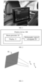
- Currently, in some high-end cars, a display is mounted behind a front seat, to play videos for watching by a passenger on a rear seat, which improves a vehicle class, and add entertainment for passengers on rear rows. In addition, full-featured high-end cars have functions such as communication, processing office affairs, surfing the Internet, and supporting connection to external game consoles. In the related art, displays for rear rows are arranged at different positions, such as a position behind a headrest of a front seat (shown in
FIG. 1 ), a position behind a backrest of a front seat, a position behind a central armrest, and a position behind on a roof over rear seats. The position behind the headrest of the front seat and the position behind the backrest of the front seat are the best positions for video watching. A size of a displayed image on a display for a rear row is about 12 inches. However, in the related art, an observation distance between human eyes and the display is about 650 mm. The distance is excessively short, and the human eyes are prone to visual fatigue and myopia when keeping looking at the small screen. In particular, when a vehicle shakes during driving, dizziness and discomfort are easily caused. - A display device, a vehicle, and a method for controlling a vehicle are provided. Eye pupils do not need to be kept in a wide-open state that causes discomfort, which avoids fatigue and myopia; experience like watching a TV series at home can be realized; and an image size can be increased without occupying more physical space of an entire vehicle.
- According to a first aspect, the present disclosure provides a display device, which includes: a beam generator, including a display and configured to generate a beam having image information displayed on the display, where a size of the display is a first preset size; and a holographic optical waveguide, configured to display an image of a second preset size at a position at a first preset distance behind the display device based on the beam having the image information, where the second preset size is a preset multiple of the first preset size; and the preset multiple is greater than 1.
- According to the display device in this embodiment of the present disclosure, the image of the second preset size is displayed, which increases an image size without occupying more physical space of an entire vehicle. The image is displayed at the position at the first preset distance behind the display device, which realizes whole experience like watching a TV series at home, and prevents eye pupils from being kept in a wide-open state that causes discomfort.
- According to a second aspect, the present disclosure provides a vehicle, which includes the display device.
- The display device is arranged at a position on a headrest or a back of a front seat of the vehicle.
- According to the vehicle in this embodiment of the present disclosure, through the display device, eye pupils do not need to be kept in a wide-open state that causes discomfort, which avoids fatigue and myopia; experience like watching a TV series at home can be realized; and an image size can be increased without occupying more physical space of an entire vehicle.
- According to a third aspect, the present disclosure provides a method for controlling a vehicle. The vehicle includes a front seat, a rear seat, and the display device. The display device is arranged at a position on a headrest or a back of the front seat. The method includes the following steps. It is determined that the display device is in an operating state. Relative positions of the display device and eyes of a passenger on the rear seat are obtained. A position of at least one of the front seat and the rear seat is adjusted when the relative positions do not meet a preset condition.
- According to the method for controlling a vehicle in this embodiment of the present disclosure, the holographic optical waveguide is adjusted by using a motor, to keep the relative positions of the display device and the eyes of the passenger on the rear seat unchanged. Therefore, eye pupils do not need to be kept in a wide-open state that causes discomfort, which avoids fatigue and myopia; experience like watching a TV series at home can be realized; and an image size can be increased without occupying more physical space of an entire vehicle.
- Part of additional aspects and advantages of the present disclosure is provided in the following description. The part will be apparent from the following description, or is learned by practice of the present disclosure.
-
-
FIG. 1 is a schematic diagram in which a display is arranged at a position behind a headrest of a front seat in the related art. -
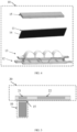
FIG. 2 is a schematic structural diagram of a display device according to an embodiment of the present disclosure. -
FIG. 3 is a schematic diagram of a size of an image displayed on a display device according to an embodiment of the present disclosure. -
FIG. 4 is a schematic structural diagram of a beam generator according to an embodiment of the present disclosure. -
FIG. 5 is a schematic structural diagram of a holographic optical waveguide according to an embodiment of the present disclosure. -
FIG. 6 is a schematic diagram of lights of a holographic optical waveguide according to an embodiment of the present disclosure. -
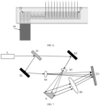
FIG. 7 is a schematic diagram in which a holographic dry plate records light information of object light and reference light according to an embodiment of the present disclosure. -
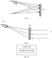
FIG. 8 is a schematic diagram of distances from object light and reference light to a holographic dry plate according to an embodiment of the present disclosure. -
FIG. 9 is a schematic diagram of reproduced light of a holographic dry plate according to an embodiment of the present disclosure. -
FIG. 10 is a schematic structural diagram of a vehicle according to an embodiment of the present disclosure. -
FIG. 11 is a schematic diagram in which a display device is arranged on a headrest of a front seat according to an embodiment of the present disclosure. -
FIG. 12 is a schematic diagram in which a display device is arranged on back of a front seat according to an embodiment of the present disclosure. -
FIG. 13 is a structural schematic diagram of a vehicle according to another embodiment of the present disclosure. -
FIG. 14 is a schematic flowchart of a method for controlling a vehicle according to an embodiment of the present disclosure. - Embodiments of the present disclosure are described in detail below, and examples of the embodiments are shown in drawings. The same or similar elements or the elements having the same or similar functions are denoted by the same or similar reference numerals throughout the description. The embodiments described below with reference to the drawings are exemplary, and are intended to explain the present disclosure and cannot be understood as a limitation on the present disclosure.
- A display device, a vehicle, and a method for controlling a vehicle in the embodiments of the present disclosure are described below with reference to
FIG. 2 to FIG. 14 . -
FIG. 2 is a schematic structural diagram of a display device according to an embodiment of the present disclosure. As shown inFIG. 2 , thedisplay device 100 includes: abeam generator 10, including adisplay 11 and configured to generate a beam having image information displayed on thedisplay 11, where a size of thedisplay 11 is a first preset size; and a holographicoptical waveguide 20, configured to display an image of a second preset size at a position at a first preset distance behind thedisplay device 100 based on the beam having the image information, where the second preset size is a preset multiple of the first preset size; and the preset multiple is greater than 1. A value of the preset multiple is in a range of 4 to 6, and a value of the first preset distance is in a range of 2500 mm to 3500 mm. - Specifically, in the related art, a seat display directly adopts a liquid crystal display (which, for example, has a size of 12 inches). A display size is a size of the display (12 inches). Human eyes directly view the display.
- Referring to
FIG. 3 , in the present disclosure, the holographicoptical waveguide 20 enables, based on a beam having image information displayed on the display 11 (the size of thedisplay 11 is the first preset size, which, for example, is 12 inches) generated by thebeam generator 10, human eyes E to view an image R1 of the second preset size (which, for example, is 50 inches) at the position at the first preset distance behind thedisplay device 100. The image of the second preset size is displayed, which increases an image size without occupying more physical space of an entire vehicle. The image is displayed at the position at the first preset distance behind thedisplay device 100, which realizes whole experience like watching a TV series at home, and prevents eye pupils from being kept in a wide-open state that causes discomfort. - In an example, the
beam generator 10 further includes alight source 12, acondenser plate 13, adiffusion plate 14, and acollimating lens 15 arranged in sequence. Thedisplay 11 is arranged between thediffusion plate 14 and thecollimating lens 15. - Specifically, in a traditional solution, a light-emitting diode (LED) lightens a liquid crystal display of 12 inches by using a light guide plate, and the human eyes directly view the display. Referring to
FIG. 4 , in the present disclosure, thelight source 12 is evenly diffused through thecondenser plate 13 and thediffusion plate 14, and lightens a small-size display 11 (which, for example, has a size of 5 inches), and the beam having the image information displayed on thedisplay 11 is then obtained through the collimatinglens 15. Thelight source 12 includes an LED light source, a laser source, or a micron light-emitting diode (micro LED) light source. Thecondenser plate 13 includes a condenser lens or a reflecting mirror. Thedisplay 11 is small and is a non-exterior display. Thedisplay 11 includes a thin film transistor (TFT) display, a digital micromirror element (DLP) display, a liquid crystal on silicon (LCOS) display, or an organic light-emitting diode (OLED) display. To reduce a volume of thebeam generator 10 and improve the display of colors, the OLED display may be further used. - In an example, the holographic
optical waveguide 20 may include: an optical waveguide coupling-instructure 21, configured to couple in the beam having the image information and propagate the beam having the image information to an optical waveguide coupling-outstructure 22; and the optical waveguide coupling-outstructure 22, configured to couple out the beam having the image information to display an image of the second preset size at a position at the first preset distance behind thedisplay device 100. The beam having the image information is a parallel beam. Thebeam generator 10 is arranged directly facing the optical waveguide coupling-instructure 21. The optical waveguide coupling-instructure 21 and the optical waveguide coupling-outstructure 22 are arranged in the same plane. - Specifically, referring to
FIG. 5 andFIG. 6 , the beam having the image information displayed on thedisplay 11 generated by thebeam generator 10 enters the optical waveguide coupling-instructure 21 using a holographic grating as a beam, passes through the optical waveguide coupling-outstructure 22 using a holographic grating as a beam, and finally forms an image of the second preset size at the position at the first preset distance behind thedisplay device 100. The image of the size of thedisplay 11, that is, the first preset size (for example, 12 inches) is magnified to the second preset size (for example, 50 inches) based on recording and imaging principles of the holographic grating, so that the human eyes E view the image of the second preset size. - It should be noted that a function of the optical waveguide is to propagate the light information in the waveguide. The light information is conducted from one end of the waveguide to an other end, but does not come out of an interface. The holographic grating is realized through interference manufacturing and diffractive reproduction, and then the holographic grating is attached to a surface of the optical waveguide to break an original interface rule of total reflection, so as to change a direction and energy of the light information propagation. In this way, the light information is transmitted into the human eye from inside of the waveguide.
- Specifically, the optical waveguide coupling-out
structure 22 includes a holographicdry plate 221. The holographicdry plate 221 has light information of object light and reference light pre-recorded therein. Distances from the object light and the reference light to the holographicdry plate 221, the preset multiple, and the first preset distance meet the following formulas:

dry plate 221. li is the first preset distance. - Recording and imaging principles of the holographic
dry plate 221 are described below with reference toFIG. 7 andFIG. 8 . - The specific principles are as follows. Referring to
FIG. 7 , a spectroscope S1 is configured to split a laser emitted by a laser device L into two lasers to produce interferential light and coherent light. A reflecting mirror S2 and a reflecting mirror S3 are configured to fold an optical path. A beam expander S4 and a beam expander S5 are configured to diffuse the condensed laser into a large-area light source, to illuminate an entire object A. A magnifying lens S6 is configured to image the image of the second preset size that is a magnified image of the object A to a position at a first preset distance behind thedisplay device 100. The holographicdry plate 221 is configured to record light information of object light O and reference light R. - Referring to
FIG. 8 , an imaging position of the object A passing through the magnifying lens S6 is a position of the object light O, and a position of the beam expander S4 is a position of the reference light R. The object light O and the reference light R are both coherent light. An expression of the object light O(x, y) and an expression R(x, y) of the reference light are respectively shown in a formula (1) and a formula (2):

dry plate 221, and Ro and Ør are respectively an amplitude and a phase of the reference light R when reaching the holographicdry plate 221. - An amplitude of an interference field is a coherent superposition of the object light and the reference light, as shown in a formula (3):

- An exposure light intensity recorded by the holographic
dry plate 221 is shown in a formula (4):
- Referring to
FIG. 9 , reproduced light C emitted from the collimatinglens 15 in thebeam generator 10 lightens the holographicdry plate 221 that freezes the foregoing information. An expression C(x, y) of the reproduced light C is shown in a formula (5), and an expression U'(x, y) of the reproduced light C after passing through holographicdry plate 221 is shown in a formula (6):


- A first term and a second term of the formula (7) are similar to the reproduced light C(x, y), but have different amplitudes. Therefore, the terms propagate in the same way as the reproduced light C. A third term includes phase information of the object A and additional information, which is most likely to reproduce the object light O. A fourth term includes information about a conjugate phase of the object A, which is most likely to form a conjugate image. When the reproduced light C is the same as the reference light R (to be specific, Ør = Øc), the third item is the phase information of the object, and therefore the reproduced object light O is a virtual image C. When the reproduced light C is conjugated with the reference light R (to be specific, Ør = -Øc), the fourth term is a real image R1 of the object, in which case an inversion of a depth of field is performed, that is, a near site is transformed into a far site. When the reproduced light C is different from and is not conjugated with the reference light R (to be specific, Ør ≠ ±Øc), the third term is equivalent to a thin lens, which may be zoomed in or out.
- It should be noted that in the present disclosure, amplified light information of the reflecting mirror or the lens is pre-recorded on the holographic
dry plate 221 by using a photosensitive material, and the lens or the reflecting mirror is not required during reproduction. In other words, the recording process and the imaging process of the holographicdry plate 221 inFIG. 7 andFIG. 8 are completed before thedisplay device 100 starts operating. Therefore, only a thickness in a range of 1.5 mm to 2.5 mm is required for the holographicoptical waveguide 20 for optical path recording, which reduces imaging space occupied by the reflecting mirror or the lens. - Referring to
FIG. 8 and FIG. 9 , lo, lc, and lr are respectively distances from the object light O, the reproduced light C, and the reference light R to the holographicdry plate 221. li is the first preset distance to the image at the position behind thedisplay device 100.
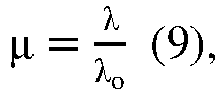


- An object-image relationship of an ordinary lens is shown in a formula (12) and a formula (13):


- The magnification M is shown in a formula (14):

- In the present disclosure, the
beam generator 10 may further include acollimating lens 15 arranged at an end, so that the reproduced light C becomes parallel light with an infinite range. When thedistance 1, from the reproduced light C to the holographicdry plate 221 is ∞, the formula (14) is
dry plate 221 is lr = 1.11 * lo. In this way, the image can be magnified from 5 inches to 50 inches. - It should be noted that designing may also be performed according to the foregoing principles based on other design requirements. For example, to implement magnification of the image from 5 inches to 50 inches (in other words, the magnification M = 10) at the imaging distance (that is, the first preset distance) of 3 meters, when a wavelength of the reproduced light C is the same as that of the reference light R, to be specific, li = 3000 mm and lc is ∞, f' = 3000 mm is obtained based on the formula (12) and the formula (13), and lo = 297.3 mm and lr = 330 mm are further obtained based on lr = 1.11 * lo. In addition, different systems can implement different magnifications and imaging at different distances, which is related to a design goal, but a principle and a method are the same.
- Based on the above, through the
display device 100, the imaging distance can be increased, so that eye pupils do not need to be kept in a wide-open state that causes discomfort, which avoids fatigue and myopia; and experience like watching a TV series at home is realized. In addition, since a resulting image is a virtual image that does not need to be received by a receiving screen, the image can be seen directly at a corresponding position in the air. Therefore, an image size can be increased without occupying more physical space of an entire vehicle, and a problem that a large-size display cannot be placed in a physical space is solved. Moreover, even if a seat exists in the physical space, neither the image is blocked nor an imaging brightness is reduced. -
FIG. 10 is a schematic structural diagram of a vehicle according to an embodiment of the present disclosure. As shown inFIG. 10 , thevehicle 200 includes the foregoingdisplay device 100. Specifically, referring toFIG. 11 and FIG. 12 , thedisplay device 100 is arranged at a position H on a headrest or a position B on a back of a front seat of thevehicle 200. A best arrangement position is mainly determined through a human-machine check of the entire vehicle, a visual check by the human eyes E, and a comfortability check. - Based on the above, according to the
vehicle 200, through thedisplay device 100, eye pupils do not need to be kept in a wide-open state that causes discomfort, which avoids fatigue and myopia; experience like watching a TV series at home can be realized; and an image size can be increased without occupying more physical space of an entire vehicle. -
FIG. 14 is a schematic flowchart of a method for controlling a vehicle according to an embodiment of the present disclosure. Referring toFIG. 13 , avehicle 200 includes afront seat 210, arear seat 220, and the foregoingdisplay device 100. Thedisplay device 100 is arranged at a position on headrest or a position on a back of thefront seat 210. As shown inFIG. 14 , the method for controlling a vehicle includes the following steps. - S101: It is determined that the
display device 100 is in an operating state. - S102: Relative positions of the
display device 100 and eyes of a passenger on therear seat 220 are obtained. - S103: A position of at least one of the
front seat 210 and therear seat 220 is adjusted when the relative positions do not meet a preset condition. - Specifically, Since the seat has an angle and an up-down position adjustment range, but the imaging position is a fixed field of view, the holographic
optical waveguide 20 needs to be adjusted by using the motor to maintain the relative positions unchanged. - It should be noted that, for other specific implementations of the method for controlling a vehicle in this embodiment of the present disclosure, reference may be to the specific implementations of the
display device 100 in the embodiments of the present disclosure. - Based on the above, according to a method for controlling a vehicle, eye pupils do not need to be kept in a wide-open state that causes discomfort, which avoids fatigue and myopia; experience like watching a TV series at home can be realized; and an image size can be increased without occupying more physical space of an entire vehicle.
- It should be noted that, the logic and/or steps shown in the flowchart or described in other manners herein, for example, may be regarded as a sequence list of executable instructions for implementing logical functions, which may be specifically implemented in any computer-readable medium for use by or in combination with an instruction execution system, a device, or an apparatus (such as a computer-based system, a system including a processor, or other systems that can fetch from an instruction execution system, a device, or an apparatus and execute the instructions). In the specification of this application, the "computer-readable medium" may be any device that can include, store, communicate, propagate, or transmit a program for use by or in combination with an instruction execution system, a device, or an apparatus. More specific examples (a non-exhaustive list) of the computer-readable storage medium include an electrical connection portion (an electronic device) with one or more wires, a portable computer case (a magnetic device), a random access memory (RAM), a read-only memory (ROM), an erasable programmable read-only memory (EPROM or a flash memory), an optical fiber device, and a portable compact disk read-only memory (CDROM). In addition, the computer-readable medium even may be paper or other suitable media on which the program can be printed, because the program can be obtained electronically, for example, by optically scanning the paper or the other media, then performing editing, interpreting, or processing in other suitable manners if necessary, and then stored in a computer memory.
- It should be understood that, parts of the present disclosure may be implemented by using hardware, software, firmware, or a combination thereof. In the foregoing implementations, a plurality of steps or methods may be implemented by using software or firmware stored in a memory and executable by a proper instruction execution system. For example, if hardware is used for implementation, same as another implementation, implementation may be performed by using any of the following technologies well known in the art or a combination thereof: a discrete logic circuit including a logic gate circuit for implementing a logic function of a data signal, a dedicated integrated circuit including a proper combinational logic gate circuit, a programmable gate array (PGA), a field programmable gate array (FPGA), and the like.
- In the descriptions of the specification, a description with reference to terms such as "an embodiment", "some embodiments", "an example", "a specific example", or "some examples" means that specific features, structures, materials, or characteristics described with reference to the embodiment or the example is included in at least one embodiment or example of the present disclosure. In this specification, schematic descriptions of the foregoing terms do not necessarily refer to the same embodiment or example. In addition, the described specific features, structures, materials, or characteristics may be combined in a proper manner in any one or more embodiments or examples.
- In the descriptions of the present disclosure, it should be understood that orientation or position relationships indicated by the terms such as "center", "longitudinal", "transverse", "length", "width", "thickness", "up", "down", "front", "back", "left", "right", "vertical", "horizontal", "top", "bottom", "inside", "outside", "clockwise", "anticlockwise", "axial direction", "radial direction", and "circumferential direction" are based on orientation or position relationships shown in the drawings, and are merely used for ease and brevity of description of the present disclosure, rather than indicating or implying that the mentioned device or element needs to have a particular orientation or be constructed and operated in a particular orientation. Therefore, such terms should not be construed as a limitation on the present disclosure.
- In addition, the terms "first" and "second" are merely used for description, and shall not be construed as indicating or implying relative importance or implying a quantity of indicated technical features. Therefore, the features defined with "first" and "second" may explicitly or implicitly include at least one of the features. In the descriptions of the present disclosure, unless explicitly specified, "multiple" means at least two, for example, two or three.
- In the present disclosure, unless otherwise explicitly specified or defined, the terms such as "mount", "connect", "connection", and "fix" should be understood in a broad sense. For example, the connection may be a fixed connection, a detachable connection, or an integral connection; or may be a mechanical connection or an electrical connection; or may be a direct connection, an indirect connection through an intermediate medium, internal communication between two elements, or an interaction relationship between two elements. A person of ordinary skill in the art can understand specific meanings of the terms in the present disclosure based on specific situations.
- In the present disclosure, unless otherwise explicitly specified and defined, a first feature being "on" or "under" a second feature may mean that the first feature is in direct contact with the second feature, or the first feature is in indirect contact with the second feature by using an intermediate medium. In addition, the first feature being "above", "over", or "on" the second feature may mean that the first feature is directly above or obliquely above the second feature, or may merely mean that the first feature is at a higher horizontal position than the second feature. The first feature being "below", "under", and "beneath" the second feature may mean that the first feature is directly below or obliquely below the second feature, or merely mean that the first feature is at a lower horizontal position than the second feature.
- Although the embodiments of the present disclosure have been shown and described above, it can be understood that, the foregoing embodiments are exemplary and should not be understood as a limitation on the present disclosure. A person of ordinary skill in the art can make changes, modifications, replacements, or variations to the foregoing embodiments within the scope of the present disclosure.
Claims (10)
- A display device, comprising:a beam generator, comprising a display and configured to generate a beam having image information displayed on the display, wherein a size of the display is a first preset size; anda holographic optical waveguide, configured to display an image of a second preset size at a position at a first preset distance behind the display device based on the beam having the image information, wherein the second preset size is a preset multiple of the first preset size; and the preset multiple is greater than 1.
- The display device according to claim 1, wherein the holographic optical waveguide comprises:an optical waveguide coupling-in structure, configured to couple in the beam having the image information and propagate the beam having the image information to an optical waveguide coupling-out structure; andthe optical waveguide coupling-out structure, configured to couple out the beam having the image information to display the image of the second preset size at the position at the first preset distance behind the display device.
- The display device according to claim 2, wherein the beam generator is arranged directly facing the optical waveguide coupling-in structure; and the optical waveguide coupling-in structure and the optical waveguide coupling-out structure are arranged in the same plane.
- The display device according to claim 2 or 3, wherein the beam having the image information is a parallel beam; the optical waveguide coupling-out structure comprises a holographic dry plate; the holographic dry plate has light information of object light and reference light pre-recorded therein; and distances from the object light and the reference light to the holographic dry plate, the preset multiple, and the first preset distance meet the following formulas:


- The display device according to claim 1, wherein the beam generator further comprises a light source, a condenser plate, a diffusion plate, and a collimating lens arranged in sequence, wherein the display is arranged between the diffusion plate and the collimating lens.
- The display device according to claim 5, wherein the light source comprises a light-emitting diode (LED) light source, a laser source, or a micron light-emitting diode (micro LED) light source; the condenser plate comprises a condenser lens or a reflecting mirror; and the display comprises a thin film transistor (TFT) display, a digital micromirror element (DLP) display, a liquid crystal on silicon (LCOS) display, or an organic light-emitting diode (OLED) display.
- The display device according to claim 1, wherein a value of the preset multiple is in a range of 4 to 6; a value of the first preset distance is in a range of 2500 mm to 3500 mm; and a thickness of the holographic optical waveguide is in a range of 1.5 mm to 2.5 mm.
- A vehicle, comprising the display device according to any of claims 1 to 7.
- The vehicle according to claim 8, wherein the display device is arranged at a position on a headrest or a back of a front seat of the vehicle.
- A method for controlling a vehicle, the vehicle comprising a front seat, a rear seat, and the display device according to any of claims 1 to 7, the display device being arranged at a position on a headrest or a back of the front seat; and the method comprising:determining that the display device is in an operating state;obtaining relative positions of the display device and eyes of a passenger on the rear seat; andadjusting a position of at least one of the front seat and the rear seat when the relative positions do not meet a preset condition.
Applications Claiming Priority (2)
| Application Number | Priority Date | Filing Date | Title |
|---|---|---|---|
| CN202111656373.0A CN116413909A (en) | 2021-12-30 | 2021-12-30 | Display device, vehicle and vehicle control method |
| PCT/CN2022/139849 WO2023125088A1 (en) | 2021-12-30 | 2022-12-19 | Display apparatus, vehicle, and control method for vehicle |
Publications (2)
| Publication Number | Publication Date |
|---|---|
| EP4393776A1 true EP4393776A1 (en) | 2024-07-03 |
| EP4393776A4 EP4393776A4 (en) | 2025-01-22 |
Family
ID=86997692
Family Applications (1)
| Application Number | Title | Priority Date | Filing Date |
|---|---|---|---|
| EP22914342.5A Pending EP4393776A4 (en) | 2021-12-30 | 2022-12-19 | DISPLAY DEVICE, VEHICLE AND CONTROL METHOD FOR VEHICLE |
Country Status (8)
| Country | Link |
|---|---|
| US (1) | US12502959B2 (en) |
| EP (1) | EP4393776A4 (en) |
| JP (1) | JP7774129B2 (en) |
| KR (1) | KR20240052023A (en) |
| CN (1) | CN116413909A (en) |
| AU (1) | AU2022427452B2 (en) |
| CA (1) | CA3233291A1 (en) |
| WO (1) | WO2023125088A1 (en) |
Families Citing this family (1)
| Publication number | Priority date | Publication date | Assignee | Title |
|---|---|---|---|---|
| CN221162235U (en) * | 2023-09-27 | 2024-06-18 | 华为技术有限公司 | Display system, vehicle and cabin system |
Family Cites Families (34)
| Publication number | Priority date | Publication date | Assignee | Title |
|---|---|---|---|---|
| JP2005067555A (en) * | 2003-08-27 | 2005-03-17 | Matsushita Electric Ind Co Ltd | Video display system and method |
| JP2005311823A (en) * | 2004-04-23 | 2005-11-04 | Seiko Epson Corp | Display device |
| CN102967999A (en) * | 2012-11-07 | 2013-03-13 | 深圳大学反光材料厂 | Interference lithography system and method based on spatial light modulator |
| JP2014169022A (en) | 2013-03-04 | 2014-09-18 | Mitsubishi Electric Corp | Monitoring device |
| CN203205055U (en) * | 2013-03-08 | 2013-09-18 | 西安鸿维光电科技有限责任公司 | A lens-free amplification digital holographic microscopy multimode recording system of pentagonal prisms |
| CN103605199B (en) * | 2013-08-30 | 2016-09-28 | 北京智谷睿拓技术服务有限公司 | Imaging device and method |
| US10732407B1 (en) | 2014-01-10 | 2020-08-04 | Rockwell Collins, Inc. | Near eye head up display system and method with fixed combiner |
| JP6422650B2 (en) | 2014-01-16 | 2018-11-14 | 矢崎総業株式会社 | Sheet device |
| JP6329792B2 (en) | 2014-03-26 | 2018-05-23 | オリンパス株式会社 | Display device |
| CN204009229U (en) | 2014-04-21 | 2014-12-10 | 象山星旗电器科技有限公司 | Display system is looked squarely in holography |
| CN104267591A (en) * | 2014-09-27 | 2015-01-07 | 郑敏 | Achromatic method based on three-time exposure technology |
| CN104534980A (en) * | 2015-02-04 | 2015-04-22 | 程灏波 | Reflection type lens-free digital holography measuring device |
| CN105137598B (en) * | 2015-07-24 | 2018-07-17 | 浙江大学 | Transparent display screen and preparation method thereof, optical system and application |
| WO2018071395A1 (en) | 2016-10-13 | 2018-04-19 | Gentex Corporation | Waveguide mirror display system |
| CN106338905B (en) * | 2016-10-31 | 2017-11-14 | 京东方科技集团股份有限公司 | A kind of display device and its display methods |
| CN106338832A (en) * | 2016-11-09 | 2017-01-18 | 苏州苏大维格光电科技股份有限公司 | Single holographic diffraction optical waveguide lens and 3D display device |
| CN106526730B (en) | 2016-11-21 | 2019-07-12 | 苏州苏大维格光电科技股份有限公司 | A kind of wide viewing angle waveguide eyeglass and production method and wear-type three-dimensional display apparatus |
| CN107390380B (en) * | 2017-05-12 | 2021-08-10 | 上海誉沛光电科技有限公司 | Display device, light guide panel and multilayer suspension display equipment |
| DE102017217193B4 (en) | 2017-09-27 | 2019-07-25 | Audi Ag | Display device, in particular for a vehicle, and vehicle with such a display device |
| US10427602B1 (en) * | 2018-06-21 | 2019-10-01 | Gm Global Technology Operations Llc. | Optical system for enhancing display viewing comfort |
| CN108957757A (en) * | 2018-08-01 | 2018-12-07 | 东南大学 | A kind of holographical wave guide display device |
| US11740460B2 (en) * | 2018-11-29 | 2023-08-29 | Apple Inc. | Optical systems with multi-layer holographic combiners |
| JP6984619B2 (en) | 2019-01-28 | 2021-12-22 | 株式会社デンソー | Virtual image display device |
| CN111694149A (en) * | 2019-03-13 | 2020-09-22 | 中强光电股份有限公司 | Near-to-eye display device |
| CN112297842A (en) | 2019-07-31 | 2021-02-02 | 宝马股份公司 | Autonomous vehicle with multiple display modes |
| DE102019121048A1 (en) * | 2019-08-05 | 2021-02-11 | Bayerische Motoren Werke Aktiengesellschaft | Waveguide-based direct view display |
| CN111812841B (en) * | 2020-03-06 | 2023-07-07 | 谷东科技有限公司 | Volume holographic grating two-dimensional pupil expansion waveguide piece and pupil expansion method thereof |
| JP7407368B2 (en) | 2020-03-30 | 2024-01-04 | パナソニックIpマネジメント株式会社 | display device |
| JP7561512B2 (en) * | 2020-04-03 | 2024-10-04 | マクセル株式会社 | Information display device |
| CN111474711B (en) * | 2020-04-09 | 2021-04-06 | 谷东科技有限公司 | Holographic waveguide display device and augmented reality display apparatus |
| CN113655615A (en) * | 2020-05-12 | 2021-11-16 | 蒋晶 | Large exit pupil optical display device, near-to-eye display device and image projection method |
| US11360429B2 (en) * | 2020-09-17 | 2022-06-14 | Pacific Light & Hologram, Inc. | Reconstructing objects with display zero order light suppression |
| US11709358B2 (en) * | 2021-02-24 | 2023-07-25 | Meta Platforms Technologies, Llc | Staircase in-coupling for waveguide display |
| US12087190B2 (en) * | 2022-07-25 | 2024-09-10 | Gm Global Teachnology Operations Llc | System for calibrating waveguide-based holographic head-up display |
-
2021
- 2021-12-30 CN CN202111656373.0A patent/CN116413909A/en active Pending
-
2022
- 2022-12-19 CA CA3233291A patent/CA3233291A1/en active Pending
- 2022-12-19 JP JP2024513009A patent/JP7774129B2/en active Active
- 2022-12-19 EP EP22914342.5A patent/EP4393776A4/en active Pending
- 2022-12-19 WO PCT/CN2022/139849 patent/WO2023125088A1/en not_active Ceased
- 2022-12-19 KR KR1020247010116A patent/KR20240052023A/en active Pending
- 2022-12-19 AU AU2022427452A patent/AU2022427452B2/en active Active
-
2024
- 2024-03-28 US US18/619,801 patent/US12502959B2/en active Active
Also Published As
| Publication number | Publication date |
|---|---|
| EP4393776A4 (en) | 2025-01-22 |
| AU2022427452A1 (en) | 2024-04-04 |
| WO2023125088A1 (en) | 2023-07-06 |
| CA3233291A1 (en) | 2023-07-06 |
| CN116413909A (en) | 2023-07-11 |
| JP2025500105A (en) | 2025-01-09 |
| US20240239196A1 (en) | 2024-07-18 |
| KR20240052023A (en) | 2024-04-22 |
| US12502959B2 (en) | 2025-12-23 |
| AU2022427452B2 (en) | 2025-09-11 |
| JP7774129B2 (en) | 2025-11-20 |
Similar Documents
| Publication | Publication Date | Title |
|---|---|---|
| JP5229327B2 (en) | Video display device, head-mounted display, and head-up display | |
| JP2009516862A (en) | Display having an image guiding substrate | |
| US12502959B2 (en) | Display device, vehicle, and method for controlling vehicle | |
| JP4452613B2 (en) | Holographic display system | |
| JP2010262232A (en) | Apparatus for displaying video image and head-mounted display | |
| CN113741036A (en) | Vehicle-mounted head-up display | |
| JPH0666038B2 (en) | Thin panel holographic display system | |
| JP2018205621A (en) | Virtual image display device, intermediate image forming part, and image display light generation unit | |
| JP7584828B2 (en) | A multiple viewing angle monitor system capable of magnified diffraction reflection | |
| WO2026066666A1 (en) | Vehicle-mounted hud system and vehicle | |
| JP5333782B2 (en) | Head-up display device | |
| US10534317B2 (en) | Display method and display apparatus | |
| JP2017077791A (en) | Image display device | |
| JP2000233665A (en) | Projection type holographic information display device for vehicles | |
| JP2011180177A (en) | Head-up display apparatus | |
| JPH0928530A (en) | Information display and display device using hologram | |
| JP2021039301A (en) | Vehicle display device | |
| CN113534476B (en) | Optical assembly, display system and manufacturing method | |
| JP6822543B2 (en) | Head-up display device | |
| JPH08146862A (en) | Hologram exposure method | |
| CN115097635B (en) | Head-up display device | |
| JP2000280786A (en) | Projection type holographic information display device for vehicles | |
| JP2017227681A (en) | Head-up display device | |
| JP2006350138A (en) | Image display device | |
| JPH1095247A (en) | Vehicle head-up display device |
Legal Events
| Date | Code | Title | Description |
|---|---|---|---|
| STAA | Information on the status of an ep patent application or granted ep patent |
Free format text: STATUS: THE INTERNATIONAL PUBLICATION HAS BEEN MADE |
|
| PUAI | Public reference made under article 153(3) epc to a published international application that has entered the european phase |
Free format text: ORIGINAL CODE: 0009012 |
|
| STAA | Information on the status of an ep patent application or granted ep patent |
Free format text: STATUS: REQUEST FOR EXAMINATION WAS MADE |
|
| 17P | Request for examination filed |
Effective date: 20240325 |
|
| AK | Designated contracting states |
Kind code of ref document: A1 Designated state(s): AL AT BE BG CH CY CZ DE DK EE ES FI FR GB GR HR HU IE IS IT LI LT LU LV MC ME MK MT NL NO PL PT RO RS SE SI SK SM TR |
|
| A4 | Supplementary search report drawn up and despatched |
Effective date: 20241223 |
|
| RIC1 | Information provided on ipc code assigned before grant |
Ipc: G02B 5/32 20060101ALI20241217BHEP Ipc: B60K 35/22 20240101ALI20241217BHEP Ipc: G02B 27/01 20060101ALI20241217BHEP Ipc: B60R 1/00 20220101AFI20241217BHEP |
|
| DAV | Request for validation of the european patent (deleted) | ||
| DAX | Request for extension of the european patent (deleted) |