EP4393742A1 - Hub reduction gear system, and vehicle - Google Patents
Hub reduction gear system, and vehicle Download PDFInfo
- Publication number
- EP4393742A1 EP4393742A1 EP22897971.2A EP22897971A EP4393742A1 EP 4393742 A1 EP4393742 A1 EP 4393742A1 EP 22897971 A EP22897971 A EP 22897971A EP 4393742 A1 EP4393742 A1 EP 4393742A1
- Authority
- EP
- European Patent Office
- Prior art keywords
- wheel
- shaft
- reducer system
- side reducer
- input
- Prior art date
- Legal status (The legal status is an assumption and is not a legal conclusion. Google has not performed a legal analysis and makes no representation as to the accuracy of the status listed.)
- Pending
Links
Images




Classifications
-
- B—PERFORMING OPERATIONS; TRANSPORTING
- B60—VEHICLES IN GENERAL
- B60K—ARRANGEMENT OR MOUNTING OF PROPULSION UNITS OR OF TRANSMISSIONS IN VEHICLES; ARRANGEMENT OR MOUNTING OF PLURAL DIVERSE PRIME-MOVERS IN VEHICLES; AUXILIARY DRIVES FOR VEHICLES; INSTRUMENTATION OR DASHBOARDS FOR VEHICLES; ARRANGEMENTS IN CONNECTION WITH COOLING, AIR INTAKE, GAS EXHAUST OR FUEL SUPPLY OF PROPULSION UNITS IN VEHICLES
- B60K17/00—Arrangement or mounting of transmissions in vehicles
- B60K17/04—Arrangement or mounting of transmissions in vehicles characterised by arrangement, location or kind of gearing
- B60K17/06—Arrangement or mounting of transmissions in vehicles characterised by arrangement, location or kind of gearing of change-speed gearing
- B60K17/08—Arrangement or mounting of transmissions in vehicles characterised by arrangement, location or kind of gearing of change-speed gearing of mechanical type
-
- B—PERFORMING OPERATIONS; TRANSPORTING
- B60—VEHICLES IN GENERAL
- B60B—VEHICLE WHEELS; CASTORS; AXLES FOR WHEELS OR CASTORS; INCREASING WHEEL ADHESION
- B60B35/00—Axle units; Parts thereof ; Arrangements for lubrication of axles
- B60B35/12—Torque-transmitting axles
- B60B35/121—Power-transmission from drive shaft to hub
- B60B35/122—Power-transmission from drive shaft to hub using gearings
-
- B—PERFORMING OPERATIONS; TRANSPORTING
- B60—VEHICLES IN GENERAL
- B60B—VEHICLE WHEELS; CASTORS; AXLES FOR WHEELS OR CASTORS; INCREASING WHEEL ADHESION
- B60B35/00—Axle units; Parts thereof ; Arrangements for lubrication of axles
- B60B35/12—Torque-transmitting axles
- B60B35/18—Arrangement of bearings
-
- B—PERFORMING OPERATIONS; TRANSPORTING
- B60—VEHICLES IN GENERAL
- B60K—ARRANGEMENT OR MOUNTING OF PROPULSION UNITS OR OF TRANSMISSIONS IN VEHICLES; ARRANGEMENT OR MOUNTING OF PLURAL DIVERSE PRIME-MOVERS IN VEHICLES; AUXILIARY DRIVES FOR VEHICLES; INSTRUMENTATION OR DASHBOARDS FOR VEHICLES; ARRANGEMENTS IN CONNECTION WITH COOLING, AIR INTAKE, GAS EXHAUST OR FUEL SUPPLY OF PROPULSION UNITS IN VEHICLES
- B60K17/00—Arrangement or mounting of transmissions in vehicles
- B60K17/04—Arrangement or mounting of transmissions in vehicles characterised by arrangement, location or kind of gearing
- B60K17/043—Transmission unit disposed in on near the vehicle wheel, or between the differential gear unit and the wheel
-
- B—PERFORMING OPERATIONS; TRANSPORTING
- B60—VEHICLES IN GENERAL
- B60K—ARRANGEMENT OR MOUNTING OF PROPULSION UNITS OR OF TRANSMISSIONS IN VEHICLES; ARRANGEMENT OR MOUNTING OF PLURAL DIVERSE PRIME-MOVERS IN VEHICLES; AUXILIARY DRIVES FOR VEHICLES; INSTRUMENTATION OR DASHBOARDS FOR VEHICLES; ARRANGEMENTS IN CONNECTION WITH COOLING, AIR INTAKE, GAS EXHAUST OR FUEL SUPPLY OF PROPULSION UNITS IN VEHICLES
- B60K17/00—Arrangement or mounting of transmissions in vehicles
- B60K17/30—Arrangement or mounting of transmissions in vehicles the ultimate propulsive elements, e.g. ground wheels, being steerable
- B60K17/303—Arrangement or mounting of transmissions in vehicles the ultimate propulsive elements, e.g. ground wheels, being steerable with a gearwheel on the steering knuckle or kingpin axis
-
- B—PERFORMING OPERATIONS; TRANSPORTING
- B62—LAND VEHICLES FOR TRAVELLING OTHERWISE THAN ON RAILS
- B62D—MOTOR VEHICLES; TRAILERS
- B62D7/00—Steering linkage; Stub axles or their mountings
- B62D7/18—Steering knuckles; King pins
-
- F—MECHANICAL ENGINEERING; LIGHTING; HEATING; WEAPONS; BLASTING
- F16—ENGINEERING ELEMENTS AND UNITS; GENERAL MEASURES FOR PRODUCING AND MAINTAINING EFFECTIVE FUNCTIONING OF MACHINES OR INSTALLATIONS; THERMAL INSULATION IN GENERAL
- F16H—GEARING
- F16H1/00—Toothed gearings for conveying rotary motion
- F16H1/02—Toothed gearings for conveying rotary motion without gears having orbital motion
- F16H1/20—Toothed gearings for conveying rotary motion without gears having orbital motion involving more than two intermeshing members
-
- F—MECHANICAL ENGINEERING; LIGHTING; HEATING; WEAPONS; BLASTING
- F16—ENGINEERING ELEMENTS AND UNITS; GENERAL MEASURES FOR PRODUCING AND MAINTAINING EFFECTIVE FUNCTIONING OF MACHINES OR INSTALLATIONS; THERMAL INSULATION IN GENERAL
- F16H—GEARING
- F16H1/00—Toothed gearings for conveying rotary motion
- F16H1/02—Toothed gearings for conveying rotary motion without gears having orbital motion
- F16H1/20—Toothed gearings for conveying rotary motion without gears having orbital motion involving more than two intermeshing members
- F16H1/22—Toothed gearings for conveying rotary motion without gears having orbital motion involving more than two intermeshing members with a plurality of driving or driven shafts; with arrangements for dividing torque between two or more intermediate shafts
-
- F—MECHANICAL ENGINEERING; LIGHTING; HEATING; WEAPONS; BLASTING
- F16—ENGINEERING ELEMENTS AND UNITS; GENERAL MEASURES FOR PRODUCING AND MAINTAINING EFFECTIVE FUNCTIONING OF MACHINES OR INSTALLATIONS; THERMAL INSULATION IN GENERAL
- F16H—GEARING
- F16H57/00—General details of gearing
- F16H57/02—Gearboxes; Mounting gearing therein
- F16H57/021—Shaft support structures, e.g. partition walls, bearing eyes, casing walls or covers with bearings
-
- F—MECHANICAL ENGINEERING; LIGHTING; HEATING; WEAPONS; BLASTING
- F16—ENGINEERING ELEMENTS AND UNITS; GENERAL MEASURES FOR PRODUCING AND MAINTAINING EFFECTIVE FUNCTIONING OF MACHINES OR INSTALLATIONS; THERMAL INSULATION IN GENERAL
- F16H—GEARING
- F16H57/00—General details of gearing
- F16H57/02—Gearboxes; Mounting gearing therein
- F16H57/029—Gearboxes; Mounting gearing therein characterised by means for sealing the gearboxes, e.g. to improve airtightness
-
- F—MECHANICAL ENGINEERING; LIGHTING; HEATING; WEAPONS; BLASTING
- F16—ENGINEERING ELEMENTS AND UNITS; GENERAL MEASURES FOR PRODUCING AND MAINTAINING EFFECTIVE FUNCTIONING OF MACHINES OR INSTALLATIONS; THERMAL INSULATION IN GENERAL
- F16J—PISTONS; CYLINDERS; SEALINGS
- F16J15/00—Sealings
- F16J15/02—Sealings between relatively-stationary surfaces
-
- B—PERFORMING OPERATIONS; TRANSPORTING
- B60—VEHICLES IN GENERAL
- B60B—VEHICLE WHEELS; CASTORS; AXLES FOR WHEELS OR CASTORS; INCREASING WHEEL ADHESION
- B60B35/00—Axle units; Parts thereof ; Arrangements for lubrication of axles
- B60B35/001—Axles of the portal type, i.e. axles designed for higher ground clearance
-
- B—PERFORMING OPERATIONS; TRANSPORTING
- B60—VEHICLES IN GENERAL
- B60Y—INDEXING SCHEME RELATING TO ASPECTS CROSS-CUTTING VEHICLE TECHNOLOGY
- B60Y2410/00—Constructional features of vehicle sub-units
- B60Y2410/10—Housings
-
- B—PERFORMING OPERATIONS; TRANSPORTING
- B60—VEHICLES IN GENERAL
- B60Y—INDEXING SCHEME RELATING TO ASPECTS CROSS-CUTTING VEHICLE TECHNOLOGY
- B60Y2410/00—Constructional features of vehicle sub-units
- B60Y2410/102—Shaft arrangements; Shaft supports, e.g. bearings
-
- F—MECHANICAL ENGINEERING; LIGHTING; HEATING; WEAPONS; BLASTING
- F16—ENGINEERING ELEMENTS AND UNITS; GENERAL MEASURES FOR PRODUCING AND MAINTAINING EFFECTIVE FUNCTIONING OF MACHINES OR INSTALLATIONS; THERMAL INSULATION IN GENERAL
- F16D—COUPLINGS FOR TRANSMITTING ROTATION; CLUTCHES; BRAKES
- F16D3/00—Yielding couplings, i.e. with means permitting movement between the connected parts during the drive
- F16D3/16—Universal joints in which flexibility is produced by means of pivots or sliding or rolling connecting parts
- F16D3/20—Universal joints in which flexibility is produced by means of pivots or sliding or rolling connecting parts one coupling part entering a sleeve of the other coupling part and connected thereto by sliding or rolling members
- F16D3/22—Universal joints in which flexibility is produced by means of pivots or sliding or rolling connecting parts one coupling part entering a sleeve of the other coupling part and connected thereto by sliding or rolling members the rolling members being balls, rollers, or the like, guided in grooves or sockets in both coupling parts
- F16D3/223—Universal joints in which flexibility is produced by means of pivots or sliding or rolling connecting parts one coupling part entering a sleeve of the other coupling part and connected thereto by sliding or rolling members the rolling members being balls, rollers, or the like, guided in grooves or sockets in both coupling parts the rolling members being guided in grooves in both coupling parts
- F16D2003/22326—Attachments to the outer joint member, i.e. attachments to the exterior of the outer joint member or to the shaft of the outer joint member
-
- F—MECHANICAL ENGINEERING; LIGHTING; HEATING; WEAPONS; BLASTING
- F16—ENGINEERING ELEMENTS AND UNITS; GENERAL MEASURES FOR PRODUCING AND MAINTAINING EFFECTIVE FUNCTIONING OF MACHINES OR INSTALLATIONS; THERMAL INSULATION IN GENERAL
- F16H—GEARING
- F16H57/00—General details of gearing
- F16H57/02—Gearboxes; Mounting gearing therein
- F16H2057/02026—Connection of auxiliaries with a gear case; Mounting of auxiliaries on the gearbox
-
- F—MECHANICAL ENGINEERING; LIGHTING; HEATING; WEAPONS; BLASTING
- F16—ENGINEERING ELEMENTS AND UNITS; GENERAL MEASURES FOR PRODUCING AND MAINTAINING EFFECTIVE FUNCTIONING OF MACHINES OR INSTALLATIONS; THERMAL INSULATION IN GENERAL
- F16H—GEARING
- F16H57/00—General details of gearing
- F16H57/02—Gearboxes; Mounting gearing therein
- F16H2057/02039—Gearboxes for particular applications
- F16H2057/02043—Gearboxes for particular applications for vehicle transmissions
- F16H2057/02052—Axle units; Transfer casings for four wheel drive
-
- F—MECHANICAL ENGINEERING; LIGHTING; HEATING; WEAPONS; BLASTING
- F16—ENGINEERING ELEMENTS AND UNITS; GENERAL MEASURES FOR PRODUCING AND MAINTAINING EFFECTIVE FUNCTIONING OF MACHINES OR INSTALLATIONS; THERMAL INSULATION IN GENERAL
- F16H—GEARING
- F16H57/00—General details of gearing
- F16H57/02—Gearboxes; Mounting gearing therein
- F16H2057/02039—Gearboxes for particular applications
- F16H2057/02043—Gearboxes for particular applications for vehicle transmissions
- F16H2057/02056—Gearboxes for particular applications for vehicle transmissions for utility vehicles, e.g. tractors or agricultural machines
Definitions
- the present disclosure aims to solve at least one of the technical problems in a related art. Therefore, one objective of the present disclosure is to provide a wheel-side reducer system.
- the wheel-side reducer system has high integration level and is relatively easy to produce.
- Another objective of the present disclosure is to provide a vehicle.
- the wheel-side reducer system is arranged in the vehicle.
- the front housing is provided with a first input hole that matches the speed reduction assembly.
- the steering main body is provided with a second input hole.
- the second input hole and the first input hole are provided opposite to each other.
- the steering main body is further provided with an avoidance space that surrounds the second input hole.
- the wheel-side reducer system further includes a transmission shaft.
- the speed reduction assembly includes an input shaft.
- the transmission shaft is connected to the input shaft through a fastener to limit the transmission shaft and the input shaft in an axial direction.
- a mounting hole is provided in the input shaft.
- the transmission shaft is arranged in the mounting hole.
- a step portion is formed on an inner wall of the mounting hole.
- An internally threaded hole is formed in the transmission shaft.
- the fastener is a bolt. The bolt is propped against the transmission shaft and is connected to an interior of the internally threaded hole.
- An external spline is provided on the transmission shaft.
- the mounting hole is provided in the input shaft.
- An internal spline is provided in the mounting hole.
- An end portion of the transmission shaft extends into the mounting hole.
- the external spline matches the internal spline.
- the wheel-side reducer system further includes: a hub bearing.
- the hub bearing is arranged in the rear housing and is sleeved over the output shaft.
- the rear housing is further provided with a limiting piece that is in limiting fit with the hub bearing in an axial direction.
- the wheel-side reducer system further includes a flange plate.
- the flange plate is fixedly connected to the output shaft.
- the hub bearing is press-fitted in the flange plate.
- the output gear is integrally molded on the output shaft.
- a vehicle according to an embodiment of a second aspect of the present disclosure includes the wheel-side reducer system according to the embodiment of the foregoing first aspect of the present disclosure.
- the wheel-side reducer system as described above is arranged, and the steering knuckle is integrally molded on the front housing, so that the production process of the housing is simplified, production efficiency is improved, the connection reliability between the steering knuckle and the front housing is improved, and the use performance of the steering knuckle is improved.
- the integration of the steering knuckle on the front housing also improves the integration level of the wheel-side reducer system and reduces the size of the wheel-side reducer system, making the design and assembly of the vehicle simpler and more reliable.
- a wheel-side reducer system 1 according to an embodiment of a first aspect of the present disclosure is described below with reference to FIG. 1 to FIG. 5 .
- the wheel-side reducer system 1 includes a housing 100, a speed reduction assembly 200, and a steering knuckle 300.
- the housing 100 includes a front housing 110 and a rear housing 120.
- the front housing 110 and the rear housing 120 are arranged opposite to each other and define an accommodating space 101 together.
- the speed reduction assembly 200 is arranged in the accommodating space 101.
- the steering knuckle 300 is integrally molded on the front housing 110.
- the wheel-side reducer system 1 may be arranged, so that rotating speed may be reduced and torque may be increased when power is transmitted to a wheel of a vehicle to improve a driving effect of the vehicle.
- the power is transmitted to the speed reduction assembly 200 to achieve effects of reducing the speed and increasing the torque.
- the speed reduction assembly 200 can transmit the torque to drive the wheel of the vehicle to rotate.
- the wheel-side reducer system 1 as described above is arranged, and the steering knuckle 300 is integrally molded on the front housing 110, so that the production process of the housing 100 is simplified, production efficiency is improved, the connection reliability between the steering knuckle 300 and the front housing 110 is improved, and the use performance of the steering knuckle 300 is improved.
- the integration of the steering knuckle 300 on the front housing 110 also improves the integration level of the wheel-side reducer system 1 and reduces the size of the wheel-side reducer system 1, making the design and assembly of the vehicle simpler and more reliable.
Landscapes
- Engineering & Computer Science (AREA)
- Mechanical Engineering (AREA)
- General Engineering & Computer Science (AREA)
- Chemical & Material Sciences (AREA)
- Combustion & Propulsion (AREA)
- Transportation (AREA)
- Gear Transmission (AREA)
- General Details Of Gearings (AREA)
- Steering-Linkage Mechanisms And Four-Wheel Steering (AREA)
Abstract
Description
- The present disclosure claims priority to and benefits of
Chinese Patent Application No. 202122964588.0, entitled "WHEEL-SIDE REDUCER SYSTEM AND VEHICLE" and filed on November 29, 2021 - The present disclosure relates to the technical field of reducers, and more specifically, to a wheel-side reducer system and a vehicle.
- In related arts, speed will be reduced and torque will be increased through a reducer before power of a vehicle is transmitted to a wheel, to enhance the power output of the vehicle. To make power transmission more reliable, transmission gears in the reducer are arranged in a rhombus pattern to improve the transmission stability of the reducer. However, this not only makes the structural design of the reducer more complex and increase the production difficulty of the reducer, but also increases the size of the reducer, affecting design and assembly of structures near the reducer, and reducing the integration level of the vehicle.
- The present disclosure aims to solve at least one of the technical problems in a related art. Therefore, one objective of the present disclosure is to provide a wheel-side reducer system. The wheel-side reducer system has high integration level and is relatively easy to produce.
- Another objective of the present disclosure is to provide a vehicle. The wheel-side reducer system is arranged in the vehicle.
- A wheel-side reducer system according to an embodiment of a first aspect of the present disclosure includes: a housing, a speed reduction assembly, and a steering knuckle. The housing includes a front housing and a rear housing. The front housing and the rear housing are arranged opposite to each other and define an accommodating space together. The speed reduction assembly is arranged in the accommodating space. The steering knuckle is integrally molded on the front housing.
- According to the wheel-side reducer system of the embodiment of the present disclosure, the integral molding of the steering knuckle on the front housing not only simplifies the production process of the housing and improves production efficiency, but also makes a connection between the steering knuckle and the front housing more reliable and improves the use performance of the steering knuckle. Meanwhile, the integration of the steering knuckle on the front housing can also improve the integration level of the wheel-side reducer system, and reduce the size of the wheel-side reducer system, thereby simplifying design and assembly processes of a vehicle. Compared with a split connection between the steering knuckle and the front housing, the integration of the steering knuckle on the front housing also reduces a wheel tread of the vehicle and reduces a turning radius.
- In some embodiments, the steering knuckle includes a steering main body and multiple mounting portions. The multiple mounting portions are arranged on an edge of the steering main body. The steering main body is integrally molded on a front surface of the front housing.
- In some embodiments, the front housing is provided with a first input hole that matches the speed reduction assembly. The steering main body is provided with a second input hole. The second input hole and the first input hole are provided opposite to each other. The steering main body is further provided with an avoidance space that surrounds the second input hole.
- In some embodiments, the speed reduction assembly includes an input shaft, a first intermediate shaft, a second intermediate shaft, and an output shaft. An input gear is arranged on the input shaft. A first intermediate gear is arranged on the first intermediate shaft. The first intermediate gear is engaged with the input gear. A second intermediate gear is arranged on the second intermediate shaft. The second intermediate gear is engaged with the input gear. An output gear is arranged on the output shaft. The output gear is engaged with each of the first intermediate gear and the second intermediate gear. Orthographic projections of a center line of the input gear, a center line of the first intermediate gear, a center line of the output gear, and a center line of the second intermediate gear are sequentially connected to form a non-rhombic quadrilateral.
- In some embodiments, the first intermediate gear and the second intermediate gear are two gears with the same modulus and different numbers of teeth.
- In some embodiments, the wheel-side reducer system further includes a transmission shaft. The speed reduction assembly includes an input shaft. The transmission shaft is connected to the input shaft through a fastener to limit the transmission shaft and the input shaft in an axial direction.
- In some embodiments, a mounting hole is provided in the input shaft. The transmission shaft is arranged in the mounting hole. A step portion is formed on an inner wall of the mounting hole. An internally threaded hole is formed in the transmission shaft. The fastener is a bolt. The bolt is propped against the transmission shaft and is connected to an interior of the internally threaded hole.
- In some embodiments, the transmission shaft is further connected to the input shaft through a spline.
- An external spline is provided on the transmission shaft. The mounting hole is provided in the input shaft. An internal spline is provided in the mounting hole. An end portion of the transmission shaft extends into the mounting hole. The external spline matches the internal spline.
- In some embodiments, the wheel-side reducer system further includes: a waterproof sealing ring. The waterproof sealing ring is arranged in the mounting hole and is sleeved over the input shaft. The waterproof sealing ring is located on an outer side of the external spline.
- In some embodiments, the wheel-side reducer system further includes: a hub bearing. The hub bearing is arranged in the rear housing and is sleeved over the output shaft. The rear housing is further provided with a limiting piece that is in limiting fit with the hub bearing in an axial direction.
- In some embodiments, the wheel-side reducer system further includes a flange plate. The flange plate is fixedly connected to the output shaft. The hub bearing is press-fitted in the flange plate.
- In some embodiments, the output gear is integrally molded on the output shaft.
- A vehicle according to an embodiment of a second aspect of the present disclosure includes the wheel-side reducer system according to the embodiment of the foregoing first aspect of the present disclosure.
- According to the vehicle of the embodiment of the present disclosure, the wheel-side reducer system as described above is arranged, and the steering knuckle is integrally molded on the front housing, so that the production process of the housing is simplified, production efficiency is improved, the connection reliability between the steering knuckle and the front housing is improved, and the use performance of the steering knuckle is improved. Meanwhile, the integration of the steering knuckle on the front housing also improves the integration level of the wheel-side reducer system and reduces the size of the wheel-side reducer system, making the design and assembly of the vehicle simpler and more reliable.
- Additional aspects and advantages of the present disclosure will be provided in the following description, and some of which will become apparent from the following description or may be learned from practices of the present disclosure.
- The foregoing and/or additional aspects and advantages of the present disclosure will become apparent and comprehensible from the following descriptions of the embodiments with reference to accompanying drawings, where:
-
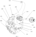
FIG. 1 is one schematic structural diagram of a wheel-side reducer system according to an embodiment of the present disclosure; -
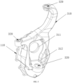
FIG. 2 is another schematic structural diagram of a wheel-side reducer system according to an embodiment of the present disclosure; -
FIG. 3 is a schematic sectional view of a wheel-side reducer system according to an embodiment of the present disclosure; -
FIG. 4 is a schematic structural diagram of a speed reduction assembly in a wheel-side reducer system according to an embodiment of the present disclosure; -
FIG. 5 is a schematic structural diagram of a front housing of a housing of a wheel-side reducer system according to an embodiment of the present disclosure; and -
FIG. 6 is a schematic block diagram of a vehicle according to an embodiment of the present disclosure. - Reference signs in the drawings:
wheel-side reducer system 1,housing 100,accommodating space 101,front housing 110,front surface 1101,rear housing 120,speed reduction assembly 200,input shaft 210,input gear 211, mountinghole 212,step portion 2121, firstintermediate shaft 220, firstintermediate gear 221, secondintermediate shaft 230, secondintermediate gear 231,output shaft 240,output gear 241, steeringknuckle 300, steeringmain body 310,second input hole 311,avoidance space 312, mountingportion 320,transmission shaft 400, internally threadedhole 4001,waterproof sealing ring 500, hub bearing 600, limitingpiece 610,flange plate 700, mountinghole 710,brake calipers 800,fastener 900,vehicle 1000. - Embodiments described with reference to accompanying drawings are explanatory. The embodiments of the present disclosure are described below in detail.
- A wheel-
side reducer system 1 according to an embodiment of a first aspect of the present disclosure is described below with reference toFIG. 1 to FIG. 5 . The wheel-side reducer system 1 includes ahousing 100, aspeed reduction assembly 200, and asteering knuckle 300. - Specifically, the
housing 100 includes afront housing 110 and arear housing 120. Thefront housing 110 and therear housing 120 are arranged opposite to each other and define anaccommodating space 101 together. Thespeed reduction assembly 200 is arranged in theaccommodating space 101. Thesteering knuckle 300 is integrally molded on thefront housing 110. - It is to be noted that, during actual design of a vehicle, the wheel-
side reducer system 1 may be arranged, so that rotating speed may be reduced and torque may be increased when power is transmitted to a wheel of a vehicle to improve a driving effect of the vehicle. - It may be understood that, during use of the wheel-
side reducer system 1, the power is transmitted to thespeed reduction assembly 200 to achieve effects of reducing the speed and increasing the torque. Meanwhile, thespeed reduction assembly 200 can transmit the torque to drive the wheel of the vehicle to rotate. - Meanwhile, the
front housing 110 and therear housing 120 form thehousing 100, so that mold stripping of thefront housing 110 and therear housing 120 is simpler, production efficiency is improved, structures of thefront housing 110 and therear housing 120 are more stable, the structural strength of thehousing 100 is improved, and theaccommodating space 101 formed by thehousing 100 is more reliable. In this way, thehousing 100 can better protect thespeed reduction assembly 200 mounted in theaccommodating space 101, thereby improving the use performance of the wheel-side reducer system 1. - In addition, the integration of the
steering knuckle 300 on thefront housing 110 can improve the integration level of the wheel-side reducer system 1 and reduce the size of the wheel-side reducer system 1, thereby facilitating the arrangement of the wheel-side reducer system 1. In addition, thesteering knuckle 300 is integrated on thefront housing 110, so that the assembled wheel-side reducer system 1 can provide space for the assembly of other parts in the vehicle, an assembly process of the vehicle is simplified, and assembly efficiency is improved. Moreover, the integration of thesteering knuckle 300 on thefront housing 110 can also make a connection between thehousing 100 and thesteering knuckle 300 more reliable and improve the use reliability of thesteering knuckle 300, thereby improving the use performance of thesteering knuckle 300, and stably controlling a travel direction of the vehicle by manipulating thesteering knuckle 300. Further, thefront housing 110 is connected to thesteering knuckle 300 in an integrally molding manner, so that production steps of thehousing 100 can be omitted, the production process of thehousing 100 can be simplified, the connection strength between thesteering knuckle 300 and thefront housing 110 can be improved, the overall structural strength of the wheel-side reducer system 1 can be improved, and the use safety and reliability of the wheel-side reducer system 1 can be improved. Compared with a split connection between a steering knuckle and a front housing, the integration of thesteering knuckle 300 on thefront housing 110 also reduces a wheel tread of the vehicle and reduces a turning radius. - According to the wheel-
side reducer system 1 of the embodiment of the present disclosure, thesteering knuckle 300 is integrally molded on thefront housing 110, so that the production process of thehousing 100 is simplified, production efficiency is simplified, a connection between thesteering knuckle 300 and thefront housing 110 is more reliable, and the use performance of thesteering knuckle 300 is improved. Meanwhile, the integration of thesteering knuckle 300 on thefront housing 110 also improves the integration level of the wheel-side reducer system 1 and reduces the size of the wheel-side reducer system 1, thereby simplifying design and assembly processes of a vehicle. - In some embodiments, as shown in
FIG. 1 , thesteering knuckle 300 includes a steeringmain body 310 and multiple mountingportions 320. The multiple mountingportions 320 are arranged on an edge of the steeringmain body 310. The steeringmain body 310 is integrally molded on afront surface 1101 of thefront housing 110. It may be understood that the multiple mountingportions 320 are configured to be connected to a suspension of a vehicle, so that thesteering knuckle 300 can not only achieve an effect of supporting the vehicle, but also control travel directions of wheels, thereby adjusting a travel direction of the vehicle. In this way, the multiple mountingportions 320 are arranged on the edge of the steeringmain body 310, so that the connection reliability between thesteering knuckle 300 and the vehicle is improved, and the use reliability of thesteering knuckle 300 is improved. In addition, the integrally molding of the steeringmain body 310 on thefront housing 110 facilitates the production and manufacturing of thefront housing 110, improves production efficiency, improves the connection reliability between thesteering knuckle 300 and thefront housing 110, and improves the connection strength between thesteering knuckle 300 and thefront housing 110, thereby improving the use performance of the wheel-side reducer system 1. - In some embodiments, as shown in
FIG. 5 , thefront housing 110 is provided with a first input hole (not shown in the figure) that matches thespeed reduction assembly 200. The steeringmain body 310 is provided with asecond input hole 311. Thesecond input hole 311 and the first input hole are provided opposite to each other. The steeringmain body 310 is further provided with anavoidance space 312 that surrounds thesecond input hole 311. In this way, the first input hole and thesecond input hole 311 are provided opposite to each other, so that atransmission shaft 400 may penetrate through the first input hole and thesecond input hole 311 to extend into thehousing 100 when the wheel-side reducer system 1 is used, power on thetransmission shaft 400 can act on the wheel-side reducer system 1 more stably to improve the power input reliability of the wheel-side reducer system 1 and to improve the use performance of the wheel-side reducer system 1. Meanwhile, theavoidance space 312 provided in the steeringmain body 310 can not only provide use space for the wheel-side reducer system 1 to realize simple and convenient use of the wheel-side reducer system 1, but also reduce production materials of thehousing 100 to reduce the production cost of the wheel-side reducer system 1. - In some embodiments, as shown in
FIG. 4 , thespeed reduction assembly 200 includes aninput shaft 210, a firstintermediate shaft 220, a secondintermediate shaft 230, and anoutput shaft 240. Aninput gear 211 is arranged on theinput shaft 210. A firstintermediate gear 221 is arranged on the firstintermediate shaft 220. The firstintermediate gear 221 is engaged with theinput gear 211. A secondintermediate gear 231 is arranged on the secondintermediate shaft 230. The secondintermediate gear 231 is engaged with theinput gear 211. Anoutput gear 241 is arranged on theoutput shaft 240. Theoutput gear 241 is engaged with each of the firstintermediate gear 221 and the secondintermediate gear 231. Orthographic projections of a center line of theinput gear 211, a center line of the firstintermediate gear 221, a center line of theoutput gear 241, and a center line of the secondintermediate gear 231 are sequentially connected to form a non-rhombic quadrilateral. - It may be understood that, after power is transmitted to the
speed reduction assembly 200 by thetransmission shaft 400, the power is transmitted through the engagement between theinput gear 211 and the firstintermediate gear 221 and between theinput gear 211 and the secondintermediate gear 231, the power is transmitted to theoutput gear 241 through the engagement between the firstintermediate gear 221 and the secondintermediate gear 231, and finally, the power is transmitted out through theoutput shaft 240 connected to theoutput gear 241 to achieve effects of reducing speed and increasing torque on the power. - Meanwhile, using the first
intermediate gear 221 and the secondintermediate gear 231 as transfer points of power transmission can improve the use stability of thespeed reduction assembly 200 and prolong the service life of the wheel-side reducer system 1. In addition, because the shape formed by sequentially connecting the orthographic projections of the center line of theinput gear 211, the center line of the firstintermediate gear 221, the center line of theoutput gear 241, and the center line of the secondintermediate gear 231 is a non-rhombic quadrilateral, available space in the wheel-side reducer system 1 can be increased to provide an assembly position forbrake calipers 800 arranged on the wheel-side reducer system 1, thereby improving the integration level of the wheel-side reducer system 1, reducing the size of the wheel-side reducer system 1, and facilitating assembly and arrangement of the wheel-side reducer system 1. - In some specific embodiments, the first
intermediate gear 221 and the secondintermediate gear 231 are two gears with the same modulus and different numbers of teeth. By such an arrangement, thespeed reduction assembly 200 may be adjusted according to user needs when thespeed reduction assembly 200 is designed and produced, so that the design of the wheel-side reducer system 1 satisfies user demands better, and meanwhile, the structural design of the wheel-side reducer system 1 can also be simplified to facilitate assembly of the wheel-side reducer system 1 and improve assembly efficiency. - In some embodiments, as shown in
FIG. 3 , the wheel-side reducer system 1 further includes thetransmission shaft 400. Afastener 900 such as a bolt is arranged between thetransmission shaft 400 and theinput shaft 210 for connecting and fixing, to limit thetransmission shaft 400 and theinput shaft 210 in an axial direction, prevent a reducer assembly from disconnecting from a connection between thetransmission shaft 400 and theinput shaft 210, and greatly reduce the risk of wheel falling off. - A mounting
hole 212 is provided in theinput shaft 210, and thetransmission shaft 400 is arranged in the mountinghole 212. Astep portion 2121 is formed on an inner wall of the mountinghole 212. An internally threadedhole 4001 is formed in thetransmission shaft 400. A bolt is propped against thetransmission shaft 400 and is connected to an interior of the internally threadedhole 4001, to connect theinput shaft 210 and thetransmission shaft 400 in an axial direction. In a specific embodiment, a gasket is further arranged between thestep portion 2121 and the bolt. - The
transmission shaft 400 is further connected to theinput shaft 210 through a spline. An external spline is provided on thetransmission shaft 400. An internal spline is provided in the mountinghole 212. An end portion of thetransmission shaft 400 extends into the mountinghole 212, and the external spline matches the internal spline. - It may be understood that, during use of the wheel-
side reducer system 1, power is transmitted to an interior of the wheel-side reducer system 1 through thetransmission shaft 400 for reducing speed and increasing torque. Therefore, thetransmission shaft 400 is connected to theinput shaft 210 in a spline connecting manner. The design of the spline has a relatively small impact on thetransmission shaft 400 and theinput shaft 210, so that the structural strength of thetransmission shaft 400 and theinput shaft 210 is improved, the transmission connection reliability between thetransmission shaft 400 and theinput shaft 210 is improved, the power can be more stably transmitted to the interior of the wheel-side reducer system 1 through thetransmission shaft 400, and the wheel-side reducer system 1 can reduce the speed and increase the torque of the power more stably. - In some embodiments, as shown in
FIG. 3 , the wheel-side reducer system 1 further includes awaterproof sealing ring 500. Thewaterproof sealing ring 500 is arranged in the mountinghole 212 and is sleeved over theinput shaft 210. Thewaterproof sealing ring 500 is located on an outer side of the external spline. - Therefore, the arrangement of the
waterproof sealing ring 500 between thetransmission shaft 400 and theinput shaft 210 can improve the waterproof effect of the wheel-side reducer system 1. By such an arrangement, water can be prevented from entering the wheel-side reducer system 1 from a connection between thetransmission shaft 400 and theinput shaft 210 to prolong the service life of the wheel-side reducer system 1, and the use reliability of the wheel-side reducer system 1 in a vehicle can be improved to improve the use performance of the wheel-side reducer system 1. - In some embodiments, as shown in
FIG. 3 , the wheel-side reducer system 1 further includes ahub bearing 600. Thehub bearing 600 is arranged in therear housing 120 and is sleeved over theoutput shaft 240. Therear housing 120 is further provided with a limitingpiece 610 that limits and matches the hub bearing 600 in an axial direction. By such an arrangement, during use of the wheel-side reducer system 1, power may be output through theoutput shaft 240 and may be output to a hub through the hub bearing 600, to adjust a travel direction of the hub. Meanwhile, the arrangement of the limitingpiece 610 in therear housing 120 can improve the connection stability between thehub bearing 600 and therear housing 120 to improve the use performance of the wheel-side reducer system 1. - In some embodiments, as shown in
FIG. 4 , the wheel-side reducer system 1 further includes aflange plate 700. Theflange plate 700 is fixedly connected to theoutput shaft 240. Thehub bearing 600 is press-fitted in theflange plate 700. Mountingholes 710 are formed in a circumference of theflange plate 700. The mountingholes 710 are used for mounting a wheel, and specifically, used for mounting thebrake calipers 800. During mounting, the hub bearing 600 is press-fitted in therear housing 120 first, and then theflange plate 700 is press-fitted with the hub bearing 600, to complete mounting. Theflange plate 700 is connected to theoutput shaft 240 through a spline. Theflange plate 700 is connected to theoutput shaft 240, so that power acts on the hub after reliably acting on theflange plate 700. Therefore, the stability of transmitting the power can be improved to control the hub more reliably, and the wheel-side reducer system 1 can be integrated with more parts to improve the integration level of the wheel-side reducer system 1 and make a structure of a vehicle simpler and reliable. In some specific embodiments, theoutput gear 241 is integrally molded on theoutput shaft 240. By such an arrangement, theoutput gear 241 is integrally molded on theoutput shaft 240, so power can be more reliably transmitted to theoutput shaft 240 when theoutput gear 241 transmits the power, power transmitting efficiency is improved, and the use performance of the wheel-side reducer system 1 is improved. - As shown in
FIG. 6 , a vehicle according to an embodiment of a second aspect of the present disclosure includes the wheel-side reducer system 1 as described in any of the foregoing embodiments of the first aspect of the present disclosure. - According to the vehicle of the embodiment of the present disclosure, the wheel-
side reducer system 1 as described above is arranged, and thesteering knuckle 300 is integrally molded on thefront housing 110, so that the production process of thehousing 100 is simplified, production efficiency is improved, the connection reliability between thesteering knuckle 300 and thefront housing 110 is improved, and the use performance of thesteering knuckle 300 is improved. Meanwhile, the integration of thesteering knuckle 300 on thefront housing 110 also improves the integration level of the wheel-side reducer system 1 and reduces the size of the wheel-side reducer system 1, making the design and assembly of the vehicle simpler and more reliable. - Other configurations and operations of the vehicle according to the embodiments of the present disclosure are known to those of ordinary skill in the art and will not be described in detail herein.
- In the description of the present specification, the descriptions of the reference terms such as "one embodiment", "some embodiments", "an exemplary embodiment", "example", "specific example", or "some examples" mean that the specific features, structures, materials or characteristics described with reference to the embodiment or example are included in at least one embodiment or example of the present disclosure. In the present specification, illustrative expressions of the foregoing terms do not necessarily refer to the same embodiment or example.
- Although the embodiments of the present disclosure have been shown and described, a person of ordinary skill in the art should understand that various changes, modifications, replacements and variations may be made to the embodiments without departing from the principles and spirit of the present disclosure, and the scope of the present disclosure is as defined by the appended claims and their equivalents.
Claims (13)
- A wheel-side reducer system (1), comprising:a housing (100), the housing (100) comprising a front housing (110) and a rear housing (120), and the front housing (110) and the rear housing (120) being arranged opposite to each other and defining an accommodating space (101) together;a speed reduction assembly (200), the speed reduction assembly (200) being arranged in the accommodating space (101); anda steering knuckle (300), the steering knuckle (300) being integrally molded on the front housing (110).
- The wheel-side reducer system (1) according to claim 1, wherein the steering knuckle (300) comprises:a steering main body (310), wherein the steering main body (310) is integrally molded on a front surface (1101) of the front housing (110); anda plurality of mounting portions (320), wherein the plurality of mounting portions (320) are arranged on an edge of the steering main body (310).
- The wheel-side reducer system (1) according to claim 2, wherein the front housing (110) is provided with a first input hole that matches the speed reduction assembly (200), the steering main body (310) is provided with a second input hole (311), the second input hole (311) and the first input hole are provided opposite to each other, and the steering main body (310) is further provided with an avoidance space (312) that surrounds the second input hole (311).
- The wheel-side reducer system (1) according to any one of claims 1 to 3, wherein the speed reduction assembly (200) comprises:an input shaft (210), wherein an input gear (211) is arranged on the input shaft (210);a first intermediate shaft (220), wherein a first intermediate gear (221) is arranged on the first intermediate shaft (220), and the first intermediate gear (221) is engaged with the input gear (211);a second intermediate shaft (230), wherein a second intermediate gear (231) is arranged on the second intermediate shaft (230), and the second intermediate gear (231) is engaged with the input gear (211); andan output shaft (240), wherein an output gear (241) is arranged on the output shaft (240), and the output gear (241) is engaged with both the first intermediate gear (221) and the second intermediate gear (231); andwherein orthographic projections of a center line of the input gear (211), a center line of the first intermediate gear (221), a center line of the output gear (241), and a center line of the second intermediate gear (231) are sequentially connected to form a non-rhombic quadrilateral.
- The wheel-side reducer system (1) according to claim 4, wherein the first intermediate gear (221) and the second intermediate gear (231) are two gears with the same modulus and different numbers of teeth.
- The wheel-side reducer system (1) according to any one of claims 1 to 3, further comprising a transmission shaft (400), the speed reduction assembly (200) comprising an input shaft (210), and the transmission shaft (400) being connected to the input shaft (210) through a fastener (900) to limit the transmission shaft (400) and the input shaft (210) in an axial direction.
- The wheel-side reducer system (1) according to claim 6, wherein a mounting hole (212) is provided in the input shaft (210), and the transmission shaft (400) is arranged in the mounting hole (212); and
a step portion (2121) is formed on an inner wall of the mounting hole (212), an internally threaded hole (4001) is formed in the transmission shaft (400), the fastener (900) is a bolt, and the bolt is propped against the transmission shaft (400) and is connected to an interior of the internally threaded hole (4001). - The wheel-side reducer system (1) according to claim 6 or 7, wherein the transmission shaft (400) is further connected to the input shaft (210) through a spline; and
an external spline is provided on the transmission shaft (400), the mounting hole (212) is provided in the input shaft (210), an internal spline is provided in the mounting hole (212), an end portion of the transmission shaft (400) extends into the mounting hole (212), and the external spline matches the internal spline. - The wheel-side reducer system (1) according to claim 8, further comprising: a waterproof sealing ring (500), the waterproof sealing ring (500) being arranged in the mounting hole (212) and being sleeved over the input shaft (210), and the waterproof sealing ring (500) being located on an outer side of the external spline.
- The wheel-side reducer system (1) according to claim 4 or 5, further comprising: a hub bearing (600), the hub bearing (600) being arranged in the rear housing (120) and being sleeved over the output shaft (240), and the rear housing (120) being further provided with a limiting piece (610) that is in limiting fit with the hub bearing (600) in an axial direction.
- The wheel-side reducer system (1) according to claim 10, further comprising: a flange plate (700), the flange plate (700) being fixedly connected to the output shaft (240), and the hub bearing (600) being press-fitted in the flange plate (700).
- The wheel-side reducer system (1) according to claim 4 or 5, wherein the output gear (241) is integrally molded on the output shaft (240).
- A vehicle (1000), comprising: the wheel-side reducer system (1) according to any one of claims 1 to 12.
Applications Claiming Priority (2)
| Application Number | Priority Date | Filing Date | Title |
|---|---|---|---|
| CN202122964588.0U CN216709019U (en) | 2021-11-29 | 2021-11-29 | Wheel Reduction Systems and Vehicles |
| PCT/CN2022/134784 WO2023093890A1 (en) | 2021-11-29 | 2022-11-28 | Hub reduction gear system, and vehicle |
Publications (2)
| Publication Number | Publication Date |
|---|---|
| EP4393742A1 true EP4393742A1 (en) | 2024-07-03 |
| EP4393742A4 EP4393742A4 (en) | 2025-07-23 |
Family
ID=81881371
Family Applications (1)
| Application Number | Title | Priority Date | Filing Date |
|---|---|---|---|
| EP22897971.2A Pending EP4393742A4 (en) | 2021-11-29 | 2022-11-28 | Hub reduction gear system and vehicle |
Country Status (6)
| Country | Link |
|---|---|
| US (1) | US12558953B2 (en) |
| EP (1) | EP4393742A4 (en) |
| JP (1) | JP7730990B2 (en) |
| KR (1) | KR20240050395A (en) |
| CN (1) | CN216709019U (en) |
| WO (1) | WO2023093890A1 (en) |
Families Citing this family (3)
| Publication number | Priority date | Publication date | Assignee | Title |
|---|---|---|---|---|
| CN216709019U (en) * | 2021-11-29 | 2022-06-10 | 比亚迪股份有限公司 | Wheel Reduction Systems and Vehicles |
| CN118770371A (en) * | 2024-07-11 | 2024-10-15 | 北京汽车集团越野车有限公司 | Steering deceleration device and vehicle |
| CN120100890A (en) * | 2025-03-31 | 2025-06-06 | 山东捷达汽车零部件有限公司 | The motor and reducer are placed in the middle of the two-in-one small-volume high-speed electric motorcycle power system |
Family Cites Families (20)
| Publication number | Priority date | Publication date | Assignee | Title |
|---|---|---|---|---|
| US1396102A (en) * | 1919-06-16 | 1921-11-08 | Militor Corp | Axle construction for motor-vehicles |
| US2895342A (en) * | 1955-07-29 | 1959-07-21 | Thomas S Hayhurst | Gearing |
| CN100339265C (en) | 2005-06-24 | 2007-09-26 | 中国航天科技集团公司第一研究院第十五研究所 | Automobile driving axle wheels set |
| AT9900U1 (en) * | 2007-01-11 | 2008-05-15 | Wfl Millturn Tech Gmbh & Co Kg | GEARBOX FOR TOOLING MACHINES |
| WO2009123254A1 (en) * | 2008-04-04 | 2009-10-08 | Ntn株式会社 | Wheel bearing apparatus and axle module |
| US8844669B2 (en) | 2008-07-10 | 2014-09-30 | Axletech International Ip Holdings, Llc | Portal wheel end |
| CN101648495A (en) * | 2008-08-15 | 2010-02-17 | 中国第一汽车集团公司 | Full-floating half axle and externally-engaged cylindrical gear portal drive axle |
| JP2010047058A (en) | 2008-08-19 | 2010-03-04 | Ntn Corp | Wheel bearing device and axle module |
| WO2011077903A1 (en) * | 2009-12-21 | 2011-06-30 | Ntn株式会社 | Wheel bearing device |
| JP2016217460A (en) * | 2015-05-21 | 2016-12-22 | Ntn株式会社 | Double-motor vehicle drive device |
| CN206416839U (en) | 2016-11-17 | 2017-08-18 | 欧孚迪汽车设计武汉有限公司 | A kind of automobile back wheel side reducer assembly |
| WO2018140774A1 (en) * | 2017-01-27 | 2018-08-02 | Traxxas Lp | Portal gear for model vehicles |
| CN110617311A (en) * | 2018-06-19 | 2019-12-27 | 郑州宇通客车股份有限公司 | Hub reduction mechanism, hub driving system and vehicle |
| US11072237B2 (en) * | 2018-11-06 | 2021-07-27 | J & J Holdings and Investments, LLC | UTV portal axle system |
| CN209671528U (en) * | 2019-03-19 | 2019-11-22 | 南京高精齿轮集团有限公司 | A kind of shunt gear-box |
| US20210023941A1 (en) * | 2019-07-26 | 2021-01-28 | Super ATV, LLC | One-piece portal wheel end mounting system |
| US11285772B2 (en) | 2019-08-23 | 2022-03-29 | Robby Gordon | Front portal spindle assembly |
| CN212400899U (en) * | 2020-06-08 | 2021-01-26 | 北京汽车集团越野车有限公司 | Hub reduction gear casing, speed reduction increase turn round device and vehicle |
| US12240318B2 (en) * | 2021-04-16 | 2025-03-04 | 74 Weld, Inc. | Multi-gear portal |
| CN216709019U (en) * | 2021-11-29 | 2022-06-10 | 比亚迪股份有限公司 | Wheel Reduction Systems and Vehicles |
-
2021
- 2021-11-29 CN CN202122964588.0U patent/CN216709019U/en active Active
-
2022
- 2022-11-28 WO PCT/CN2022/134784 patent/WO2023093890A1/en not_active Ceased
- 2022-11-28 EP EP22897971.2A patent/EP4393742A4/en active Pending
- 2022-11-28 JP JP2024519802A patent/JP7730990B2/en active Active
- 2022-11-28 KR KR1020247009535A patent/KR20240050395A/en active Pending
-
2024
- 2024-04-08 US US18/628,878 patent/US12558953B2/en active Active
Also Published As
| Publication number | Publication date |
|---|---|
| US20240253459A1 (en) | 2024-08-01 |
| KR20240050395A (en) | 2024-04-18 |
| JP2024535113A (en) | 2024-09-26 |
| WO2023093890A1 (en) | 2023-06-01 |
| CN216709019U (en) | 2022-06-10 |
| US12558953B2 (en) | 2026-02-24 |
| EP4393742A4 (en) | 2025-07-23 |
| JP7730990B2 (en) | 2025-08-28 |
Similar Documents
| Publication | Publication Date | Title |
|---|---|---|
| US12558953B2 (en) | Wheel-side reducer system and vehicle | |
| JPH0274401A (en) | Full floating type axle assembly for car | |
| CN113581357B (en) | A driving device for an electric tricycle | |
| CN201434023Y (en) | Long-distance high-efficient constant-velocity transmission shaft | |
| CN113202910B (en) | Low-cost differential mechanism structure between wheels | |
| CN211398443U (en) | Electric drive assembly for heavy vehicle | |
| CN205417165U (en) | Electric automobile driving axle assembly | |
| CN203743367U (en) | Shell assembly for differential mechanism and differential mechanism and vehicle provided with shell assembly | |
| CN211009796U (en) | Differential mechanism assembly | |
| CN116852974A (en) | Wheel-side electric driving system capable of automatically switching modes and control method | |
| CN213711784U (en) | Cross axle differential mechanism | |
| CN211667117U (en) | A kind of adjustment and locking assembly of differential bearing | |
| CN211869078U (en) | Drive axle and sleeve flange thereof | |
| CN221090487U (en) | Wheel reduction | |
| CN109114204B (en) | Commercial vehicle wheel reduction gear shell | |
| CN116771883A (en) | Novel through-type transaxle main reducer assembly | |
| CN218326073U (en) | Integral type tricycle differential case | |
| CN220168486U (en) | Inter-axle differential housing assembly with herringbone axle | |
| CN217874046U (en) | High stability automotive differential assembly | |
| CN220870015U (en) | Speed reducer output end module and cycloid speed reducer | |
| CN214888742U (en) | Commercial car turns to bevel gear angle reduction gear wheel bearing structure | |
| CN218367255U (en) | Wheel excavator drive axle assembly | |
| CN209818689U (en) | Gear shifting differential case | |
| CN224135126U (en) | Differential device, power assembly and vehicle | |
| CN221195798U (en) | Duplex constant velocity universal joint structure |
Legal Events
| Date | Code | Title | Description |
|---|---|---|---|
| STAA | Information on the status of an ep patent application or granted ep patent |
Free format text: STATUS: THE INTERNATIONAL PUBLICATION HAS BEEN MADE |
|
| PUAI | Public reference made under article 153(3) epc to a published international application that has entered the european phase |
Free format text: ORIGINAL CODE: 0009012 |
|
| STAA | Information on the status of an ep patent application or granted ep patent |
Free format text: STATUS: REQUEST FOR EXAMINATION WAS MADE |
|
| 17P | Request for examination filed |
Effective date: 20240327 |
|
| AK | Designated contracting states |
Kind code of ref document: A1 Designated state(s): AL AT BE BG CH CY CZ DE DK EE ES FI FR GB GR HR HU IE IS IT LI LT LU LV MC ME MK MT NL NO PL PT RO RS SE SI SK SM TR |
|
| DAV | Request for validation of the european patent (deleted) | ||
| DAX | Request for extension of the european patent (deleted) | ||
| REG | Reference to a national code |
Ref country code: DE Ref legal event code: R079 Free format text: PREVIOUS MAIN CLASS: B60K0017080000 Ipc: B60K0017300000 |
|
| RIC1 | Information provided on ipc code assigned before grant |
Ipc: F16D 3/223 20110101ALN20250326BHEP Ipc: F16H 57/02 20120101ALN20250326BHEP Ipc: B60B 35/00 20060101ALI20250326BHEP Ipc: B60B 35/12 20060101ALI20250326BHEP Ipc: B62D 7/18 20060101ALI20250326BHEP Ipc: F16D 1/06 20060101ALI20250326BHEP Ipc: F16H 57/021 20120101ALI20250326BHEP Ipc: F16H 1/22 20060101ALI20250326BHEP Ipc: B60K 17/04 20060101ALI20250326BHEP Ipc: B60K 17/30 20060101AFI20250326BHEP |
|
| A4 | Supplementary search report drawn up and despatched |
Effective date: 20250624 |
|
| RIC1 | Information provided on ipc code assigned before grant |
Ipc: B60K 17/30 20060101AFI20250617BHEP Ipc: B60K 17/04 20060101ALI20250617BHEP Ipc: F16H 1/22 20060101ALI20250617BHEP Ipc: F16H 57/021 20120101ALI20250617BHEP Ipc: F16D 1/06 20060101ALI20250617BHEP Ipc: B62D 7/18 20060101ALI20250617BHEP Ipc: B60B 35/12 20060101ALI20250617BHEP Ipc: B60B 35/00 20060101ALI20250617BHEP Ipc: F16H 57/02 20120101ALN20250617BHEP Ipc: F16D 3/223 20110101ALN20250617BHEP |