EP4393736A1 - Drive device for vehicle - Google Patents
Drive device for vehicle Download PDFInfo
- Publication number
- EP4393736A1 EP4393736A1 EP22876229.0A EP22876229A EP4393736A1 EP 4393736 A1 EP4393736 A1 EP 4393736A1 EP 22876229 A EP22876229 A EP 22876229A EP 4393736 A1 EP4393736 A1 EP 4393736A1
- Authority
- EP
- European Patent Office
- Prior art keywords
- power transmission
- rear direction
- electric machine
- rotary electric
- drive device
- Prior art date
- Legal status (The legal status is an assumption and is not a legal conclusion. Google has not performed a legal analysis and makes no representation as to the accuracy of the status listed.)
- Pending
Links
Images

Classifications
-
- F—MECHANICAL ENGINEERING; LIGHTING; HEATING; WEAPONS; BLASTING
- F16—ENGINEERING ELEMENTS AND UNITS; GENERAL MEASURES FOR PRODUCING AND MAINTAINING EFFECTIVE FUNCTIONING OF MACHINES OR INSTALLATIONS; THERMAL INSULATION IN GENERAL
- F16H—GEARING
- F16H57/00—General details of gearing
- F16H57/04—Features relating to lubrication or cooling or heating
- F16H57/045—Lubricant storage reservoirs, e.g. reservoirs in addition to a gear sump for collecting lubricant in the upper part of a gear case
-
- F—MECHANICAL ENGINEERING; LIGHTING; HEATING; WEAPONS; BLASTING
- F16—ENGINEERING ELEMENTS AND UNITS; GENERAL MEASURES FOR PRODUCING AND MAINTAINING EFFECTIVE FUNCTIONING OF MACHINES OR INSTALLATIONS; THERMAL INSULATION IN GENERAL
- F16H—GEARING
- F16H57/00—General details of gearing
- F16H57/04—Features relating to lubrication or cooling or heating
- F16H57/0457—Splash lubrication
-
- F—MECHANICAL ENGINEERING; LIGHTING; HEATING; WEAPONS; BLASTING
- F16—ENGINEERING ELEMENTS AND UNITS; GENERAL MEASURES FOR PRODUCING AND MAINTAINING EFFECTIVE FUNCTIONING OF MACHINES OR INSTALLATIONS; THERMAL INSULATION IN GENERAL
- F16H—GEARING
- F16H57/00—General details of gearing
- F16H57/04—Features relating to lubrication or cooling or heating
- F16H57/0467—Elements of gearings to be lubricated, cooled or heated
- F16H57/0476—Electric machines and gearing, i.e. joint lubrication or cooling or heating thereof
-
- F—MECHANICAL ENGINEERING; LIGHTING; HEATING; WEAPONS; BLASTING
- F16—ENGINEERING ELEMENTS AND UNITS; GENERAL MEASURES FOR PRODUCING AND MAINTAINING EFFECTIVE FUNCTIONING OF MACHINES OR INSTALLATIONS; THERMAL INSULATION IN GENERAL
- F16H—GEARING
- F16H57/00—General details of gearing
- F16H57/04—Features relating to lubrication or cooling or heating
- F16H57/048—Type of gearings to be lubricated, cooled or heated
- F16H57/0482—Gearings with gears having orbital motion
- F16H57/0483—Axle or inter-axle differentials
-
- F—MECHANICAL ENGINEERING; LIGHTING; HEATING; WEAPONS; BLASTING
- F16—ENGINEERING ELEMENTS AND UNITS; GENERAL MEASURES FOR PRODUCING AND MAINTAINING EFFECTIVE FUNCTIONING OF MACHINES OR INSTALLATIONS; THERMAL INSULATION IN GENERAL
- F16H—GEARING
- F16H57/00—General details of gearing
- F16H57/04—Features relating to lubrication or cooling or heating
- F16H57/048—Type of gearings to be lubricated, cooled or heated
- F16H57/0493—Gearings with spur or bevel gears
- F16H57/0495—Gearings with spur or bevel gears with fixed gear ratio
-
- F—MECHANICAL ENGINEERING; LIGHTING; HEATING; WEAPONS; BLASTING
- F16—ENGINEERING ELEMENTS AND UNITS; GENERAL MEASURES FOR PRODUCING AND MAINTAINING EFFECTIVE FUNCTIONING OF MACHINES OR INSTALLATIONS; THERMAL INSULATION IN GENERAL
- F16H—GEARING
- F16H63/00—Control outputs from the control unit to change-speed- or reversing-gearings for conveying rotary motion or to other devices than the final output mechanism
- F16H63/02—Final output mechanisms therefor; Actuating means for the final output mechanisms
- F16H63/30—Constructional features of the final output mechanisms
- F16H63/34—Locking or disabling mechanisms
- F16H63/3416—Parking lock mechanisms or brakes in the transmission
- F16H63/3425—Parking lock mechanisms or brakes in the transmission characterised by pawls or wheels
-
- F—MECHANICAL ENGINEERING; LIGHTING; HEATING; WEAPONS; BLASTING
- F16—ENGINEERING ELEMENTS AND UNITS; GENERAL MEASURES FOR PRODUCING AND MAINTAINING EFFECTIVE FUNCTIONING OF MACHINES OR INSTALLATIONS; THERMAL INSULATION IN GENERAL
- F16H—GEARING
- F16H63/00—Control outputs from the control unit to change-speed- or reversing-gearings for conveying rotary motion or to other devices than the final output mechanism
- F16H63/02—Final output mechanisms therefor; Actuating means for the final output mechanisms
- F16H63/30—Constructional features of the final output mechanisms
- F16H63/34—Locking or disabling mechanisms
- F16H63/3416—Parking lock mechanisms or brakes in the transmission
- F16H63/3425—Parking lock mechanisms or brakes in the transmission characterised by pawls or wheels
- F16H63/3433—Details of latch mechanisms, e.g. for keeping pawls out of engagement
-
- F—MECHANICAL ENGINEERING; LIGHTING; HEATING; WEAPONS; BLASTING
- F16—ENGINEERING ELEMENTS AND UNITS; GENERAL MEASURES FOR PRODUCING AND MAINTAINING EFFECTIVE FUNCTIONING OF MACHINES OR INSTALLATIONS; THERMAL INSULATION IN GENERAL
- F16H—GEARING
- F16H63/00—Control outputs from the control unit to change-speed- or reversing-gearings for conveying rotary motion or to other devices than the final output mechanism
- F16H63/02—Final output mechanisms therefor; Actuating means for the final output mechanisms
- F16H63/30—Constructional features of the final output mechanisms
- F16H63/34—Locking or disabling mechanisms
- F16H63/3416—Parking lock mechanisms or brakes in the transmission
- F16H63/3458—Parking lock mechanisms or brakes in the transmission with electric actuating means, e.g. shift by wire
- F16H63/3466—Parking lock mechanisms or brakes in the transmission with electric actuating means, e.g. shift by wire using electric motors
-
- B—PERFORMING OPERATIONS; TRANSPORTING
- B60—VEHICLES IN GENERAL
- B60K—ARRANGEMENT OR MOUNTING OF PROPULSION UNITS OR OF TRANSMISSIONS IN VEHICLES; ARRANGEMENT OR MOUNTING OF PLURAL DIVERSE PRIME-MOVERS IN VEHICLES; AUXILIARY DRIVES FOR VEHICLES; INSTRUMENTATION OR DASHBOARDS FOR VEHICLES; ARRANGEMENTS IN CONNECTION WITH COOLING, AIR INTAKE, GAS EXHAUST OR FUEL SUPPLY OF PROPULSION UNITS IN VEHICLES
- B60K1/00—Arrangement or mounting of electrical propulsion units
- B60K2001/001—Arrangement or mounting of electrical propulsion units one motor mounted on a propulsion axle for rotating right and left wheels of this axle
-
- B—PERFORMING OPERATIONS; TRANSPORTING
- B60—VEHICLES IN GENERAL
- B60K—ARRANGEMENT OR MOUNTING OF PROPULSION UNITS OR OF TRANSMISSIONS IN VEHICLES; ARRANGEMENT OR MOUNTING OF PLURAL DIVERSE PRIME-MOVERS IN VEHICLES; AUXILIARY DRIVES FOR VEHICLES; INSTRUMENTATION OR DASHBOARDS FOR VEHICLES; ARRANGEMENTS IN CONNECTION WITH COOLING, AIR INTAKE, GAS EXHAUST OR FUEL SUPPLY OF PROPULSION UNITS IN VEHICLES
- B60K1/00—Arrangement or mounting of electrical propulsion units
- B60K1/04—Arrangement or mounting of electrical propulsion units of the electric storage means for propulsion
- B60K2001/0405—Arrangement or mounting of electrical propulsion units of the electric storage means for propulsion characterised by their position
-
- B—PERFORMING OPERATIONS; TRANSPORTING
- B60—VEHICLES IN GENERAL
- B60Y—INDEXING SCHEME RELATING TO ASPECTS CROSS-CUTTING VEHICLE TECHNOLOGY
- B60Y2410/00—Constructional features of vehicle sub-units
- B60Y2410/10—Housings
-
- F—MECHANICAL ENGINEERING; LIGHTING; HEATING; WEAPONS; BLASTING
- F16—ENGINEERING ELEMENTS AND UNITS; GENERAL MEASURES FOR PRODUCING AND MAINTAINING EFFECTIVE FUNCTIONING OF MACHINES OR INSTALLATIONS; THERMAL INSULATION IN GENERAL
- F16H—GEARING
- F16H1/00—Toothed gearings for conveying rotary motion
- F16H1/02—Toothed gearings for conveying rotary motion without gears having orbital motion
- F16H1/20—Toothed gearings for conveying rotary motion without gears having orbital motion involving more than two intermeshing members
-
- F—MECHANICAL ENGINEERING; LIGHTING; HEATING; WEAPONS; BLASTING
- F16—ENGINEERING ELEMENTS AND UNITS; GENERAL MEASURES FOR PRODUCING AND MAINTAINING EFFECTIVE FUNCTIONING OF MACHINES OR INSTALLATIONS; THERMAL INSULATION IN GENERAL
- F16H—GEARING
- F16H57/00—General details of gearing
- F16H57/02—Gearboxes; Mounting gearing therein
- F16H2057/02034—Gearboxes combined or connected with electric machines
-
- F—MECHANICAL ENGINEERING; LIGHTING; HEATING; WEAPONS; BLASTING
- F16—ENGINEERING ELEMENTS AND UNITS; GENERAL MEASURES FOR PRODUCING AND MAINTAINING EFFECTIVE FUNCTIONING OF MACHINES OR INSTALLATIONS; THERMAL INSULATION IN GENERAL
- F16H—GEARING
- F16H37/00—Combinations of mechanical gearings, not provided for in groups F16H1/00 - F16H35/00
- F16H37/02—Combinations of mechanical gearings, not provided for in groups F16H1/00 - F16H35/00 comprising essentially only toothed or friction gearings
- F16H37/06—Combinations of mechanical gearings, not provided for in groups F16H1/00 - F16H35/00 comprising essentially only toothed or friction gearings with a plurality of driving or driven shafts; with arrangements for dividing torque between two or more intermediate shafts
- F16H37/08—Combinations of mechanical gearings, not provided for in groups F16H1/00 - F16H35/00 comprising essentially only toothed or friction gearings with a plurality of driving or driven shafts; with arrangements for dividing torque between two or more intermediate shafts with differential gearing
- F16H37/0806—Combinations of mechanical gearings, not provided for in groups F16H1/00 - F16H35/00 comprising essentially only toothed or friction gearings with a plurality of driving or driven shafts; with arrangements for dividing torque between two or more intermediate shafts with differential gearing with a plurality of driving or driven shafts
- F16H37/0813—Combinations of mechanical gearings, not provided for in groups F16H1/00 - F16H35/00 comprising essentially only toothed or friction gearings with a plurality of driving or driven shafts; with arrangements for dividing torque between two or more intermediate shafts with differential gearing with a plurality of driving or driven shafts with only one input shaft
-
- F—MECHANICAL ENGINEERING; LIGHTING; HEATING; WEAPONS; BLASTING
- F16—ENGINEERING ELEMENTS AND UNITS; GENERAL MEASURES FOR PRODUCING AND MAINTAINING EFFECTIVE FUNCTIONING OF MACHINES OR INSTALLATIONS; THERMAL INSULATION IN GENERAL
- F16H—GEARING
- F16H48/00—Differential gearings
- F16H48/06—Differential gearings with gears having orbital motion
- F16H48/08—Differential gearings with gears having orbital motion comprising bevel gears
-
- Y—GENERAL TAGGING OF NEW TECHNOLOGICAL DEVELOPMENTS; GENERAL TAGGING OF CROSS-SECTIONAL TECHNOLOGIES SPANNING OVER SEVERAL SECTIONS OF THE IPC; TECHNICAL SUBJECTS COVERED BY FORMER USPC CROSS-REFERENCE ART COLLECTIONS [XRACs] AND DIGESTS
- Y02—TECHNOLOGIES OR APPLICATIONS FOR MITIGATION OR ADAPTATION AGAINST CLIMATE CHANGE
- Y02T—CLIMATE CHANGE MITIGATION TECHNOLOGIES RELATED TO TRANSPORTATION
- Y02T10/00—Road transport of goods or passengers
- Y02T10/60—Other road transportation technologies with climate change mitigation effect
- Y02T10/62—Hybrid vehicles
Definitions
- the present invention relates to a vehicle drive device including a rotary electric machine to be a drive power source for wheels, a parking assembly, and a case accommodating the vehicle drive device and the parking assembly.
- Patent Literature 1 An example vehicle drive device is described in Patent Literature 1 below. Reference signs in parentheses used below in describing the background and the technical problem are the reference signs in Patent Literature 1.
- Patent Literature 1 WO 2011/141947
- the vehicle drive device described in Patent Literature 1 includes the first power transmission (30, 41, 42, 45) and the second power transmission located below the reservoir (77) and aligned in a front-rear direction (lateral direction in FIG. 2 in Patent Literature 1) that is perpendicular to an axial direction of the rotary electric machine when viewed vertically.
- the vehicle drive device cannot be smaller in the front-rear direction.
- a vehicle drive device including a rotary electric machine and a parking assembly is to be smaller in the front-rear direction.
- the reservoir and the second power transmission are located above the first power transmission.
- the area of the reservoir in the front-rear direction, the area of the first power transmission in the front-rear direction, and the area of the second power transmission in the front-rear direction overlap the area of the rotary electric machine in the front-rear direction.
- the areas of the reservoir, the first power transmission, and the second power transmission are located within an area relatively near the rotation axis of the rotary electric machine in the front-rear direction. This allows the vehicle drive device including the rotary electric machine and the parking assembly to be smaller in the front-rear direction.
- the vehicle drive device 100 includes a rotary electric machine 1, a first power transmission 6, a parking assembly 7, and a case 9.
- the vehicle drive device 100 further includes an inverter 10.
- the rotary electric machine 1 is to be a drive power source for wheels WH (refer to FIG. 2 ).
- the rotary electric machine 1 includes a stator 11 and a rotor 12 supported in a manner rotatable relative to the stator 11.
- the rotary electric machine 1 functions as a motor (electric motor) that receives electricity to generate power and as a generator (electric generator) that receives power to generate electricity.
- the rotary electric machine 1 is electrically connected to an electric storage device (not shown) such as a battery or a capacitor.
- the rotary electric machine 1 runs on electricity stored in the electric storage device to generate a driving force.
- the rotary electric machine 1 also generates electricity from a driving force transmitted from the wheels WH and charges the electric storage device.
- the inverter 10 controls the rotary electric machine 1.
- the inverter 10 is electrically connected to the rotary electric machine 1 and the electric storage device described above and converts power between direct current (DC) for the electric storage device and polyphase (three-phase in this example) alternating current (AC) for the rotary electric machine 1.
- the inverter 10 includes a switching device unit including multiple switching devices forming an inverter circuit, a smoothing capacitor for smoothing a voltage from a DC power supply in the inverter circuit, and a control board for controlling the inverter circuit.
- the case 9 includes a first compartment A1, a second compartment A2, a third compartment A3, and a fourth compartment A4.
- the first compartment A1 is a space accommodating the rotary electric machine 1.
- the second compartment A2 is a space accommodating the input member 2 and the counter gear assembly 5.
- the third compartment A3 is a space accommodating the pair of output members 3 and the differential gear assembly 4.
- the fourth compartment A4 is a space accommodating the inverter 10.
- the case 9 includes a partition wall 91, a first peripheral wall 92a, a first side wall 92b, a second peripheral wall 93a, a second side wall 93b, a third peripheral wall 94a, a third side wall 94b, a fourth side wall 94c, a compartment wall 95a, and a lid 95b.
- the second peripheral wall 93a covers the input member 2 and the counter gear assembly 5 from outside in the radial direction R.
- the second side wall 93b covers ends of the input member 2 and the counter gear assembly 5 in the second axial direction L2.
- the second peripheral wall 93a is integral with a portion of the second side wall 93b located in the second axial direction L2 from the input member 2 and the counter gear assembly 5.
- the second peripheral wall 93a, the second side wall 93b, and the fourth side wall 94c integrally form a third case portion 9C.
- the third case portion 9C is joined to the first case portion 9A from a position in the second axial direction L2.
- the first case portion 9A (partition wall 91) covers an opening defined by the second peripheral wall 93a in the first axial direction L1.
- the second compartment A2 is defined by the partition wall 91, the second peripheral wall 93a, and the second side wall 93b.
- the partition wall 91, the second peripheral wall 93a, and the second side wall 93b in the case 9 surround the space defined as the second compartment A2.
- the third compartment A3 is defined by the third peripheral wall 94a, the third side wall 94b, and the fourth side wall 94c.
- the third peripheral wall 94a, the third side wall 94b, and the fourth side wall 94c in the case 9 surround the space defined as the third compartment A3.
- the second compartment A2 and the third compartment A3 are continuous with each other.
- the stator 11 in the rotary electric machine 1 includes a cylindrical stator core 111.
- the stator core 111 is fixed to a nonrotatable member.
- the stator core 111 is fixed to the first peripheral wall 92a of the case 9 as the nonrotatable member.
- the rotor 12 in the rotary electric machine 1 includes a cylindrical rotor core 121.
- the rotor core 121 is supported in a manner rotatable relative to the stator core 111.
- the rotor 12 further includes a rotor shaft 122 connected to the rotor core 121 to rotate integrally with the rotor core 121.
- the rotor shaft 122 extends along the first axis X1.
- the rotor shaft 122 is cylindrical and has the first axis X1 as its axis.
- the rotary electric machine 1 is an inner-rotor rotary electric machine.
- the stator 11 is located outward from the rotor 12 in the radial direction R.
- the stator core 111 is located outward from the rotor core 121 in the radial direction R.
- the rotor shaft 122 is located inward from the rotor core 121 in the radial direction R.
- Being drivably connected herein refers to two rotatable elements being connected to allow transmission of a driving force, including the two rotatable elements being connected to rotate integrally or the two rotatable elements being connected to allow transmission of a driving force with one or more transmission members in between.
- the transmission member include a shaft, a gear assembly, and a chain, which are members for transmitting rotation at a constant speed or at a variable speed.
- the transmission member may include a friction engagement device or an intermeshing engagement device, which are engagement devices for transmitting rotation and a driving force selectively.
- the input gear 21 is connected to the input shaft 22 to rotate integrally with the input shaft 22.
- the input gear 21 is integral with the input shaft 22.
- the input shaft 22 is connected to the parking gear 71 to rotate integrally with the parking gear 71.
- the input shaft 22 and the parking gear 71 are connected to each other with splines.
- the counter gear assembly 5 includes a counter input gear 51 that meshes with the input gear 21, a counter output gear 52 rotatable integrally with the counter input gear 51, and a counter shaft 53 connecting the gears 51 and 52.
- the counter input gear 51 and the counter output gear 52 are connected with the counter shaft 53 in between to rotate integrally.
- the counter shaft 53 extends along the third axis X3.
- the counter input gear 51 is connected to the counter shaft 53 with splines.
- the counter output gear 52 is integral with the counter shaft 53.
- the counter output gear 52 has a smaller diameter than the counter input gear 51.
- the area of the counter output gear 52 in the axial direction L overlaps the area of the parking gear 71 in the axial direction L.
- the differential gear assembly 4 distributes rotation transmitted from the input member 2 to the pair of output members 3.
- the differential gear assembly 4 includes a differential input gear 41 as an input element for the differential gear assembly 4.
- the differential gear assembly 4 thus distributes rotation of the differential input gear 41 to the pair of output members 3.
- the differential gear assembly 4 further includes a differential case 42, a pair of pinion gears 43, and a pair of side gears 44.
- the pair of pinion gears 43 and the pair of side gears 44 are bevel gears.
- the differential case 42 is a hollow member accommodating the pair of pinion gears 43 and the pair of side gears 44.
- the differential case 42 is connected to the differential input gear 41 to rotate integrally with the differential input gear 41.
- the differential input gear 41 is connected to the differential case 42 by bolt fastening.
- the pair of pinion gears 43 face each other at an interval in the radial direction R of the second axis X2.
- the pair of pinion gears 43 are attached to a pinion shaft 43a that is supported to rotate integrally with the differential case 42.
- the pair of pinion gears 43 can each rotate about the pinion shaft 43a and revolve around the second axis X2.
- the pair of side gears 44 mesh with the pair of pinion gears 43.
- the pair of side gears 44 rotate about the second axis X2 as their rotation axis.
- the pair of side gears 44 face each other with the pinion shaft 43a in between at an interval in the axial direction L.
- the pair of output members 3 are drivably connected to the respective wheels WH (refer to FIG. 2 ).
- the pair of output members 3 are connected to the respective side gears 44 to rotate integrally with the respective side gears 44.
- one of the pair of output members 3 extends through the third side wall 94b in the axial direction L, and the other of the output members 3 extends through the fourth side wall 94c in the axial direction L.
- the pair of output members 3 are each connected to a drive shaft DS that is drivably connected to the corresponding wheel WH to rotate integrally with the drive shaft DS.
- each of the pair of output members 3 is cylindrical and has the second axis X2 as its axis.
- the pair of output members 3 each receive the corresponding drive shaft DS inward in the radial direction R.
- the output member 3 and the drive shaft DS are connected to each other with splines.
- a vertical direction for the vehicle drive device 100 in the in-vehicle state is hereafter referred to as a vertical direction V. Upward and downward in the vertical direction V are simply referred to as upward and downward.
- a direction perpendicular to the axial direction L when viewed in the vertical direction V is referred to as a front-rear direction W.
- One direction in the front-rear direction W is referred to as a rearward direction W1, and the other direction in the front-rear direction W is referred to as a frontward direction W2.
- the area of the first power transmission 6 in the vertical direction V overlaps the area of the rotary electric machine 1 in the vertical direction V
- the areas of the input member 2, the differential gear assembly 4, and the counter gear assembly 5 included in the first power transmission 6 in the vertical direction V overlap the area of the rotary electric machine 1 in the vertical direction V
- the parking assembly 7 includes an engagement member 72 selectively engageable with the parking gear 71, and a second power transmission 73 that transmits power to the engagement member 72.
- the second power transmission 73 includes a transmission shaft 74, a connector 75, and a pressing member 76.
- the vehicle drive device 100 includes a reservoir 8.
- the reservoir 8 is in the case 9.
- the reservoir 8 stores oil.
- the reservoir 8 includes a first reservoir 81 and a second reservoir 82 located below the first reservoir 81.
- the reservoir 8 is a catch tank that receives and stores oil splashed by, for example, the differential input gear 41 and the counter input gear 51 and supplies oil to a space including supply targets (e.g., bearings, gear meshing portions, the rotor 12 in the rotary electric machine 1, the first coil end 112, and the second coil end 113).
- supply targets e.g., bearings, gear meshing portions, the rotor 12 in the rotary electric machine 1, the first coil end 112, and the second coil end 113.
- the area of the input member 2 in the first power transmission 6 in the front-rear direction W fully overlaps the area of the rotary electric machine 1 in the front-rear direction W, and the area of the counter gear assembly 5 in the first power transmission 6 in the front-rear direction W partially overlaps the area of the rotary electric machine 1 in the front-rear direction W.
- the areas of the connector 75 and the pressing member 76 in the second power transmission 73 in the front-rear direction W fully overlaps the area of the rotary electric machine 1 in the front-rear direction W, and the area of the transmission shaft 74 in the second power transmission 73 in the front-rear direction W partially overlaps the area of the rotary electric machine 1 in the front-rear direction W.
- the pivotable portion 722 extends with its portion nearer the parking gear 71 being higher than its portion near the fifth axis X5.
- the pivotable portion 722 extends from the fifth axis X5 to an area between the first axis X1 and the pressing member 76 in the front-rear direction W and above the first axis X1 as the rotation axis of the parking gear 71.
- the press portion 721 extends upward from the upper end of the pivotable portion 722.
- the second power transmission 73 includes the transmission shaft 74 extending through the connection hole 9a connecting the outside and the inside of the case 9 and rotatably supported about its axis.
- the parking assembly 7 further includes the drive source 77 that drives the transmission shaft 74 to rotate.
- the drive source 77 is located outside the case 9.
Landscapes
- Engineering & Computer Science (AREA)
- General Engineering & Computer Science (AREA)
- Mechanical Engineering (AREA)
- Electric Propulsion And Braking For Vehicles (AREA)
- General Details Of Gearings (AREA)
- Arrangement Or Mounting Of Propulsion Units For Vehicles (AREA)
- Retarders (AREA)
Abstract
Description
- The present invention relates to a vehicle drive device including a rotary electric machine to be a drive power source for wheels, a parking assembly, and a case accommodating the vehicle drive device and the parking assembly.
- An example vehicle drive device is described in
Patent Literature 1 below. Reference signs in parentheses used below in describing the background and the technical problem are the reference signs inPatent Literature 1. - A vehicle drive device described in
Patent Literature 1 includes a first power transmission (30, 41, 42, 45) that transmits power between a rotary electric machine and wheels, and a reservoir (77) to store oil included in a case 9 (refer toFIG. 3 in Patent Literature 1). The vehicle drive device described inPatent Literature 1 includes a parking assembly (52) including a parking gear (51), an engagement member (62) selectively engageable with the parking gear, and a second power transmission that transmits power to the engagement member (refer toFIG. 2 in Patent Literature 1). The second power transmission includes, for example, a transmission shaft (56) extending across the outside and the inside of the case (4) and rotatably supported about its axis. - Patent Literature 1:
WO 2011/141947 - The vehicle drive device described in
Patent Literature 1 includes the first power transmission (30, 41, 42, 45) and the second power transmission located below the reservoir (77) and aligned in a front-rear direction (lateral direction inFIG. 2 in Patent Literature 1) that is perpendicular to an axial direction of the rotary electric machine when viewed vertically. Thus, the vehicle drive device cannot be smaller in the front-rear direction. - A vehicle drive device including a rotary electric machine and a parking assembly is to be smaller in the front-rear direction.
- In response to the above, a vehicle drive device includes a rotary electric machine to be a drive power source for wheels, a first power transmission that transmits power between the rotary electric machine and the wheels, a parking assembly, a case accommodating the rotary electric machine, the parking assembly, and at least a part of the first power transmission, and a reservoir in the case. The reservoir stores oil. The parking assembly includes a parking gear in a rotary member included in the first power transmission and movable with the wheels, an engagement member selectively engageable with the parking gear, and a second power transmission that transmits power to the engagement member. The parking gear is coaxial with the rotary electric machine. The reservoir and the second power transmission are located above the first power transmission. An area of the reservoir in a front-rear direction, an area of the first power transmission in the front-rear direction, and an area of the second power transmission in the front-rear direction overlap an area of the rotary electric machine in the front-rear direction, where the front-rear direction is a direction perpendicular to an axial direction of the rotary electric machine when viewed in a vertical direction.
- In this structure with the above aspect, the reservoir and the second power transmission are located above the first power transmission. The area of the reservoir in the front-rear direction, the area of the first power transmission in the front-rear direction, and the area of the second power transmission in the front-rear direction overlap the area of the rotary electric machine in the front-rear direction. Thus, the areas of the reservoir, the first power transmission, and the second power transmission are located within an area relatively near the rotation axis of the rotary electric machine in the front-rear direction. This allows the vehicle drive device including the rotary electric machine and the parking assembly to be smaller in the front-rear direction.
-
-
FIG. 1 is a cross-sectional view of a vehicle drive device according to an embodiment taken in an axial direction. -
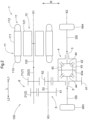
FIG. 2 is a skeleton diagram of the vehicle drive device according to the embodiment. -
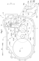
FIG. 3 is a diagram of the vehicle drive device according to the embodiment, describing the positional relationship between its elements when viewed axially. -
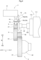
FIG. 4 is a diagram of the vehicle drive device according to the embodiment, describing the positional relationship between its elements when viewed vertically. - A
vehicle drive device 100 according to an embodiment will now be described with reference to the drawings. As shown inFIGs. 1 and2 , thevehicle drive device 100 includes a rotaryelectric machine 1, afirst power transmission 6, aparking assembly 7, and acase 9. In the present embodiment, thevehicle drive device 100 further includes aninverter 10. - The rotary
electric machine 1 is to be a drive power source for wheels WH (refer toFIG. 2 ). The rotaryelectric machine 1 includes astator 11 and arotor 12 supported in a manner rotatable relative to thestator 11. The rotaryelectric machine 1 functions as a motor (electric motor) that receives electricity to generate power and as a generator (electric generator) that receives power to generate electricity. More specifically, the rotaryelectric machine 1 is electrically connected to an electric storage device (not shown) such as a battery or a capacitor. The rotaryelectric machine 1 runs on electricity stored in the electric storage device to generate a driving force. The rotaryelectric machine 1 also generates electricity from a driving force transmitted from the wheels WH and charges the electric storage device. - The
inverter 10 controls the rotaryelectric machine 1. In the present embodiment, theinverter 10 is electrically connected to the rotaryelectric machine 1 and the electric storage device described above and converts power between direct current (DC) for the electric storage device and polyphase (three-phase in this example) alternating current (AC) for the rotaryelectric machine 1. In this example, theinverter 10 includes a switching device unit including multiple switching devices forming an inverter circuit, a smoothing capacitor for smoothing a voltage from a DC power supply in the inverter circuit, and a control board for controlling the inverter circuit. - The
first power transmission 6 transmits power between the rotaryelectric machine 1 and the wheels WH. In the present embodiment, thefirst power transmission 6 includes aninput member 2, a pair ofoutput members 3, adifferential gear assembly 4, and acounter gear assembly 5. - The
parking assembly 7 includes aparking gear 71 in a rotary member included in thefirst power transmission 6 and movable with the wheels WH. In the present embodiment, theparking gear 71 is located in theinput member 2. - The
parking gear 71 is located on a first axis X1 as the rotation axis of therotor 12. In other words, theparking gear 71 is coaxial with the rotaryelectric machine 1. Theinput member 2 is also located on the first axis X1 in the present embodiment. In the present embodiment, the pair ofoutput members 3 and thedifferential gear assembly 4 are located on a second axis X2 different from the first axis X1. Thecounter gear assembly 5 is located on a third axis X3 different from the first axis X1 and the second axis X2 in the present embodiment. In this example, the axes X1 to X3 are parallel to one another. - The direction parallel to the axes X1 to X3 is hereafter referred to as an axial direction L for the
vehicle drive device 100. One direction in the axial direction L is referred to as a first axial direction L1, and the opposite direction is referred to as a second axial direction L2. In the present embodiment, the rotaryelectric machine 1 is located in the first axial direction L1 from theinput member 2 in the axial direction L. The direction opposite to the first axial direction L1 is referred to as the second axial direction L2. The directions perpendicular to the axes X1 to X3 are referred to as radial directions R of the axes. A radial direction R of any of the axes or a radial direction R of an apparent reference axis may be simply referred to as a radial direction R. - As shown in
FIG. 1 , thecase 9 accommodates the rotaryelectric machine 1 and theparking assembly 7. Thecase 9 further accommodates at least a part of thefirst power transmission 6. In the present embodiment, thecase 9 also accommodates theinput member 2, the pair ofoutput members 3, thedifferential gear assembly 4, and thecounter gear assembly 5. The pair ofoutput members 3 are accommodated in thecase 9 with parts of theoutput members 3 exposed outside thecase 9. - The
case 9 includes a first compartment A1, a second compartment A2, a third compartment A3, and a fourth compartment A4. In the present embodiment, the first compartment A1 is a space accommodating the rotaryelectric machine 1. The second compartment A2 is a space accommodating theinput member 2 and thecounter gear assembly 5. The third compartment A3 is a space accommodating the pair ofoutput members 3 and thedifferential gear assembly 4. The fourth compartment A4 is a space accommodating theinverter 10. - In the present embodiment, the
case 9 includes apartition wall 91, a firstperipheral wall 92a, afirst side wall 92b, a secondperipheral wall 93a, asecond side wall 93b, a thirdperipheral wall 94a, athird side wall 94b, afourth side wall 94c, acompartment wall 95a, and alid 95b. - The
partition wall 91 separates the first compartment A1 and the second compartment A2. In the present embodiment, thepartition wall 91 extends in the radial direction R. In other words, thepartition wall 91 separates the first compartment A1 and the second compartment A2 in the axial direction L. - The first
peripheral wall 92a covers the rotaryelectric machine 1 from outside in the radial direction R. Thefirst side wall 92b covers an end of the rotaryelectric machine 1 in the first axial direction L1. In the present embodiment, the firstperipheral wall 92a is cylindrical and defines an opening in the first axial direction L1. The opening defined by the firstperipheral wall 92a in the first axial direction L1 is covered with thefirst side wall 92b. The firstperipheral wall 92a is integral with thepartition wall 91 in its portion located in the second axial direction L2 from the rotaryelectric machine 1. In this example, thepartition wall 91, the firstperipheral wall 92a, the thirdperipheral wall 94a, thethird side wall 94b, and thecompartment wall 95a integrally form afirst case portion 9A. Asecond case portion 9B including thefirst side wall 92b is joined to thefirst case portion 9A from a position in the first axial direction L1. - The second
peripheral wall 93a covers theinput member 2 and thecounter gear assembly 5 from outside in the radial direction R. Thesecond side wall 93b covers ends of theinput member 2 and thecounter gear assembly 5 in the second axial direction L2. In the present embodiment, the secondperipheral wall 93a is integral with a portion of thesecond side wall 93b located in the second axial direction L2 from theinput member 2 and thecounter gear assembly 5. In this example, the secondperipheral wall 93a, thesecond side wall 93b, and thefourth side wall 94c integrally form athird case portion 9C. Thethird case portion 9C is joined to thefirst case portion 9A from a position in the second axial direction L2. Thus, thefirst case portion 9A (partition wall 91) covers an opening defined by the secondperipheral wall 93a in the first axial direction L1. - The third
peripheral wall 94a covers the pair ofoutput members 3 and thedifferential gear assembly 4 from outside in the radial direction R. Thethird side wall 94b covers an end of thedifferential gear assembly 4 in the first axial direction L1. Thefourth side wall 94c covers an end of thedifferential gear assembly 4 in the second axial direction L2. In the present embodiment, the thirdperipheral wall 94a and thethird side wall 94b are integral with thefirst case portion 9A. The thirdperipheral wall 94a defines, in the second axial direction L2, an opening that is covered with thefourth side wall 94c. As described above, thefourth side wall 94c is integral with the secondperipheral wall 93a and thesecond side wall 93b. - In the present embodiment, the first compartment A1 is defined by the
partition wall 91, the firstperipheral wall 92a, and thefirst side wall 92b. In other words, thepartition wall 91, the firstperipheral wall 92a, and thefirst side wall 92b in thecase 9 surround the space defined as the first compartment A1. - In the present embodiment, the second compartment A2 is defined by the
partition wall 91, the secondperipheral wall 93a, and thesecond side wall 93b. In other words, thepartition wall 91, the secondperipheral wall 93a, and thesecond side wall 93b in thecase 9 surround the space defined as the second compartment A2. In the present embodiment, the third compartment A3 is defined by the thirdperipheral wall 94a, thethird side wall 94b, and thefourth side wall 94c. In other words, the thirdperipheral wall 94a, thethird side wall 94b, and thefourth side wall 94c in thecase 9 surround the space defined as the third compartment A3. In the present embodiment, the second compartment A2 and the third compartment A3 are continuous with each other. - In the present embodiment, the fourth compartment A4 is defined by the
compartment wall 95a and thelid 95b. In other words, thecompartment wall 95a and thelid 95b in thecase 9 surround the space defined as the fourth compartment A4. - The
compartment wall 95a is cylindrical and surrounds sides of theinverter 10. In the present embodiment, thecompartment wall 95a extends, in an in-vehicle state, upward from the firstperipheral wall 92a and the secondperipheral wall 93a, defining an opening for theinverter 10 to be placed into or removed from the fourth compartment A4. The in-vehicle state herein refers to thevehicle drive device 100 being mounted on a vehicle. As described above, thecompartment wall 95a is integral with thepartition wall 91, the firstperipheral wall 92a, the thirdperipheral wall 94a, and thethird side wall 94b. - The
lid 95b covers the opening defined by thecompartment wall 95a. In the present embodiment, thelid 95b is attachable to and detachable from thecompartment wall 95a. - The
stator 11 in the rotaryelectric machine 1 includes acylindrical stator core 111. Thestator core 111 is fixed to a nonrotatable member. In the present embodiment, thestator core 111 is fixed to the firstperipheral wall 92a of thecase 9 as the nonrotatable member. Therotor 12 in the rotaryelectric machine 1 includes acylindrical rotor core 121. Therotor core 121 is supported in a manner rotatable relative to thestator core 111. In the present embodiment, therotor 12 further includes arotor shaft 122 connected to therotor core 121 to rotate integrally with therotor core 121. Therotor shaft 122 extends along the first axis X1. In the present embodiment, therotor shaft 122 is cylindrical and has the first axis X1 as its axis. - In the present embodiment, the rotary
electric machine 1 is an inner-rotor rotary electric machine. In other words, thestator 11 is located outward from therotor 12 in the radial direction R. Thus, thestator core 111 is located outward from therotor core 121 in the radial direction R. Therotor shaft 122 is located inward from therotor core 121 in the radial direction R. - In the present embodiment, the rotary
electric machine 1 is a rotary electric machine operable with a rotating field. Thus, thestator core 111 is wound with a stator coil. In the present embodiment, the stator coil is wound around thestator core 111 with afirst coil end 112 protruding from thestator core 111 in the first axial direction L1 and asecond coil end 113 protruding from thestator core 111 in the second axial direction L2. Although not shown, therotor core 121 includes permanent magnets. - The
input member 2 is drivably connected to therotor 12 in the rotaryelectric machine 1. In the present embodiment, theinput member 2 includes aninput gear 21 and aninput shaft 22. - Being drivably connected herein refers to two rotatable elements being connected to allow transmission of a driving force, including the two rotatable elements being connected to rotate integrally or the two rotatable elements being connected to allow transmission of a driving force with one or more transmission members in between. Examples of the transmission member include a shaft, a gear assembly, and a chain, which are members for transmitting rotation at a constant speed or at a variable speed. Examples of the transmission member may include a friction engagement device or an intermeshing engagement device, which are engagement devices for transmitting rotation and a driving force selectively.
- The
input gear 21 is connected to theinput shaft 22 to rotate integrally with theinput shaft 22. In the example shown inFIG. 1 , theinput gear 21 is integral with theinput shaft 22. - The
input shaft 22 extends along the first axis X1. In the present embodiment, theinput shaft 22 extends in the axial direction L through thepartition wall 91 in thecase 9 and is connected to therotor shaft 122 to rotate integrally with therotor shaft 122. In the example shown inFIG. 1 , theinput shaft 22 has an end in the first axial direction L1 located inward in the radial direction R from an end of therotor shaft 122 in the second axial direction L2. These ends are engaged with splines and are connected to each other to rotate integrally. - In the present embodiment, the
input shaft 22 is connected to theparking gear 71 to rotate integrally with theparking gear 71. In the example shown inFIG. 1 , theinput shaft 22 and theparking gear 71 are connected to each other with splines. - The
counter gear assembly 5 includes acounter input gear 51 that meshes with theinput gear 21, acounter output gear 52 rotatable integrally with thecounter input gear 51, and acounter shaft 53 connecting thegears - The
counter input gear 51 and thecounter output gear 52 are connected with thecounter shaft 53 in between to rotate integrally. Thecounter shaft 53 extends along the third axis X3. In the example shown inFIG. 1 , thecounter input gear 51 is connected to thecounter shaft 53 with splines. Thecounter output gear 52 is integral with thecounter shaft 53. In the example shown inFIG. 1 , thecounter output gear 52 has a smaller diameter than thecounter input gear 51. The area of thecounter output gear 52 in the axial direction L overlaps the area of theparking gear 71 in the axial direction L. - The
differential gear assembly 4 distributes rotation transmitted from theinput member 2 to the pair ofoutput members 3. In the present embodiment, thedifferential gear assembly 4 includes adifferential input gear 41 as an input element for thedifferential gear assembly 4. Thedifferential gear assembly 4 thus distributes rotation of thedifferential input gear 41 to the pair ofoutput members 3. - In the present embodiment, the
differential gear assembly 4 further includes adifferential case 42, a pair of pinion gears 43, and a pair of side gears 44. The pair of pinion gears 43 and the pair of side gears 44 are bevel gears. - The
differential case 42 is a hollow member accommodating the pair of pinion gears 43 and the pair of side gears 44. Thedifferential case 42 is connected to thedifferential input gear 41 to rotate integrally with thedifferential input gear 41. In the example shown inFIG. 1 , thedifferential input gear 41 is connected to thedifferential case 42 by bolt fastening. - The pair of pinion gears 43 face each other at an interval in the radial direction R of the second axis X2. The pair of pinion gears 43 are attached to a
pinion shaft 43a that is supported to rotate integrally with thedifferential case 42. The pair of pinion gears 43 can each rotate about thepinion shaft 43a and revolve around the second axis X2. - The pair of side gears 44 mesh with the pair of pinion gears 43. The pair of side gears 44 rotate about the second axis X2 as their rotation axis. The pair of side gears 44 face each other with the
pinion shaft 43a in between at an interval in the axial direction L. - The pair of
output members 3 are drivably connected to the respective wheels WH (refer toFIG. 2 ). In the present embodiment, the pair ofoutput members 3 are connected to the respective side gears 44 to rotate integrally with the respective side gears 44. In the present embodiment, one of the pair ofoutput members 3 extends through thethird side wall 94b in the axial direction L, and the other of theoutput members 3 extends through thefourth side wall 94c in the axial direction L. The pair ofoutput members 3 are each connected to a drive shaft DS that is drivably connected to the corresponding wheel WH to rotate integrally with the drive shaft DS. In the example shown inFIG. 1 , each of the pair ofoutput members 3 is cylindrical and has the second axis X2 as its axis. The pair ofoutput members 3 each receive the corresponding drive shaft DS inward in the radial direction R. Theoutput member 3 and the drive shaft DS are connected to each other with splines. - A vertical direction for the
vehicle drive device 100 in the in-vehicle state is hereafter referred to as a vertical direction V. Upward and downward in the vertical direction V are simply referred to as upward and downward. A direction perpendicular to the axial direction L when viewed in the vertical direction V is referred to as a front-rear direction W. One direction in the front-rear direction W is referred to as a rearward direction W1, and the other direction in the front-rear direction W is referred to as a frontward direction W2. - In the present embodiment, as shown in
FIG. 3 , the area of thefirst power transmission 6 in the vertical direction V overlaps the area of the rotaryelectric machine 1 in the vertical direction V In the example shown inFIG. 3 , the areas of theinput member 2, thedifferential gear assembly 4, and thecounter gear assembly 5 included in thefirst power transmission 6 in the vertical direction V overlap the area of the rotaryelectric machine 1 in the vertical direction V - As shown in
FIG. 3 , theparking assembly 7 includes anengagement member 72 selectively engageable with theparking gear 71, and asecond power transmission 73 that transmits power to theengagement member 72. - In the present embodiment, the
second power transmission 73 includes atransmission shaft 74, aconnector 75, and a pressingmember 76. - The
transmission shaft 74 is rotatably supported about a fourth axis X4 as an axis of thetransmission shaft 74. Thetransmission shaft 74 extends through aconnection hole 9a that connects the outside and the inside of thecase 9. In the present embodiment, the fourth axis X4 extends in the front-rear direction W. Theconnection hole 9a thus extends through thecase 9 in the front-rear direction W. Although not shown, theconnection hole 9a includes a seal that seals, in an oil-tight manner, a space between theconnection hole 9a and thetransmission shaft 74. - The
connector 75 connects the pressingmember 76 and thetransmission shaft 74. Theconnector 75 is connected to thetransmission shaft 74 to rotate integrally with thetransmission shaft 74. Theconnector 75 also supports the pressingmember 76 in a rotatable manner. In the present embodiment, thetransmission shaft 74 extends through theconnector 75 in the front-rear direction W. The pressingmember 76 is supported by theconnector 75 to rotate about an axis extending in the front-rear direction W different from the fourth axis X4 as the rotation axis of thetransmission shaft 74. Thus, in response to the rotation of thetransmission shaft 74, the pressingmember 76 moves in the vertical direction V with theconnector 75 in between. Although not shown, theconnector 75 in this example is a detent lever that maintains its orientation with a detent spring and includes protrusions and recesses engageable with a roller in the detent spring. - The pressing
member 76 presses apress portion 721 included in theengagement member 72. In the present embodiment, the pressingmember 76 includes a connectingportion 761 and acam 762. - The connecting
portion 761 is rotatably connected to theconnector 75. In the present embodiment, the connectingportion 761 extends through theconnector 75 in the front-rear direction W and is supported by theconnector 75. - The
cam 762 changes the orientation of theengagement member 72 along the shape of the surface of thecam 762. In the present embodiment, thecam 762 is located below the connectingportion 761. Thecam 762 extends in the vertical direction V - As shown in
FIG. 3 , thevehicle drive device 100 includes areservoir 8. Thereservoir 8 is in thecase 9. Thereservoir 8 stores oil. In the present embodiment, thereservoir 8 includes afirst reservoir 81 and asecond reservoir 82 located below thefirst reservoir 81. In this example, thereservoir 8 is a catch tank that receives and stores oil splashed by, for example, thedifferential input gear 41 and thecounter input gear 51 and supplies oil to a space including supply targets (e.g., bearings, gear meshing portions, therotor 12 in the rotaryelectric machine 1, thefirst coil end 112, and the second coil end 113). - The
reservoir 8 and thesecond power transmission 73 are located above thefirst power transmission 6. In the example shown inFIG. 3 , thefirst reservoir 81 is located above theinput member 2 and thecounter gear assembly 5 in thefirst power transmission 6. Thesecond reservoir 82 is located above theinput member 2 in thefirst power transmission 6. In the example shown inFIG. 3 , thetransmission shaft 74 in thesecond power transmission 73 is located above theinput member 2, thedifferential gear assembly 4, and thecounter gear assembly 5 in thefirst power transmission 6. Theconnector 75 in thesecond power transmission 73 is located above theinput member 2 and thecounter gear assembly 5 in thefirst power transmission 6. The pressingmember 76 in thesecond power transmission 73 is above theinput member 2 in thefirst power transmission 6. - The area of the
reservoir 8 in the front-rear direction W, the area of thefirst power transmission 6 in the front-rear direction W, and the area of thesecond power transmission 73 in the front-rear direction W overlap the area of the rotaryelectric machine 1 in the front-rear direction W. In the example shown inFIG. 3 , the areas of thefirst reservoir 81 and thesecond reservoir 82 in the front-rear direction W fully overlap the area of the rotaryelectric machine 1 in the front-rear direction W. The area of theinput member 2 in thefirst power transmission 6 in the front-rear direction W fully overlaps the area of the rotaryelectric machine 1 in the front-rear direction W, and the area of thecounter gear assembly 5 in thefirst power transmission 6 in the front-rear direction W partially overlaps the area of the rotaryelectric machine 1 in the front-rear direction W. The areas of theconnector 75 and the pressingmember 76 in thesecond power transmission 73 in the front-rear direction W fully overlaps the area of the rotaryelectric machine 1 in the front-rear direction W, and the area of thetransmission shaft 74 in thesecond power transmission 73 in the front-rear direction W partially overlaps the area of the rotaryelectric machine 1 in the front-rear direction W. - As described above, the
vehicle drive device 100 includes the rotaryelectric machine 1 to be the drive power source for the wheels WH, thefirst power transmission 6 that transmits power between the rotaryelectric machine 1 and the wheels WH, theparking assembly 7, thecase 9 accommodating the rotaryelectric machine 1, theparking assembly 7, and at least a part of thefirst power transmission 6, and thereservoir 8 in thecase 9. Thereservoir 8 stores oil. Theparking assembly 7 includes theparking gear 71 in the rotary member (input member 2 in this example) included in thefirst power transmission 6 and movable with the wheels WH, theengagement member 72 selectively engageable with theparking gear 71, and thesecond power transmission 73 that transmits power to theengagement member 72. Theparking gear 71 is coaxial with the rotaryelectric machine 1. Thereservoir 8 and thesecond power transmission 73 are located above thefirst power transmission 6. The area of thereservoir 8 in the front-rear direction W, the area of thefirst power transmission 6 in the front-rear direction W, and the area of thesecond power transmission 73 in the front-rear direction W overlap the area of the rotaryelectric machine 1 in the front-rear direction W, where the front-rear direction W is a direction perpendicular to the axial direction L of the rotaryelectric machine 1 when viewed in the vertical direction V - In this structure, the
reservoir 8 and thesecond power transmission 73 are located above thefirst power transmission 6. The area of thereservoir 8 in the front-rear direction W, the area of thefirst power transmission 6 in the front-rear direction W, and the area of thesecond power transmission 73 in the front-rear direction W overlap the area of the rotaryelectric machine 1 in the front-rear direction W. Thus, the areas of thereservoir 8 and thesecond power transmission 73 can be located within an area relatively near the rotation axis (first axis X1) of the rotaryelectric machine 1 in the front-rear direction W. This allows thevehicle drive device 100 including the rotaryelectric machine 1 and theparking assembly 7 to be smaller in the front-rear direction W. - As shown in
FIG. 3 , thereservoir 8 in the present embodiment is located above theparking gear 71 and overlaps thesecond power transmission 73 in theparking assembly 7 when viewed in the front-rear direction W. In the example shown inFIG. 3 , thefirst reservoir 81 overlaps theconnector 75 and the pressingmember 76 in thesecond power transmission 73 when viewed in the front-rear direction, and thesecond reservoir 82 overlaps the pressingmember 76 in thesecond power transmission 73 when viewed in the front-rear direction. - Thus, in the present embodiment, the
reservoir 8 is located above theparking gear 71 and overlaps thesecond power transmission 73 when viewed in the front-rear direction W. - This structure allows a space above the
parking gear 71 to receive thereservoir 8 and thesecond power transmission 73. Thus, thevehicle drive device 100 may easily be smaller. - In the present embodiment, the
differential gear assembly 4 is located in the rearward direction W1 from thereservoir 8. Thesecond power transmission 73 is located in the frontward direction W2 from thereservoir 8. - Thus, in the present embodiment, the
first power transmission 6 includes theinput member 2 drivably connected to therotor 12 in the rotaryelectric machine 1, the pair ofoutput members 3 drivably connected to the respective wheels WH, and thedifferential gear assembly 4 that distributes rotation transmitted from theinput member 2 to the pair ofoutput members 3. Thedifferential gear assembly 4 is located opposite to thesecond power transmission 73 across thereservoir 8 in the front-rear direction W. - This structure is more likely to include spaces for receiving the
differential gear assembly 4 and thesecond power transmission 73 than a structure in which thedifferential gear assembly 4 and thesecond power transmission 73 are located in the same direction from thereservoir 8 in the front-rear direction W. - In the present embodiment, the
second power transmission 73 overlaps the rotaryelectric machine 1 when viewed in the axial direction L. In the example shown inFIG. 3 , the pressingmember 76 in thesecond power transmission 73 overlaps the rotaryelectric machine 1 when viewed axially. Two elements overlapping when viewed in a specific direction herein refers to two elements each having at least a portion to intersect with an imaginary line parallel to the specific viewing direction being moved to a direction perpendicular to the imaginary line. - This structure is more likely to downsize the
vehicle drive device 100 in the radial direction R, which includes the front-rear direction W and the vertical direction V, of the rotaryelectric machine 1 than a structure in which thesecond power transmission 73 has no overlap with the rotaryelectric machine 1 when viewed in the axial direction L. - In the present embodiment, the
transmission shaft 74 in thesecond power transmission 73 extends through theconnection hole 9a, and the area of theconnection hole 9a in the front-rear direction W overlaps the area of the rotaryelectric machine 1 in the front-rear direction W. - Thus, in the present embodiment, the
second power transmission 73 includes thetransmission shaft 74 extending through theconnection hole 9a connecting the outside and the inside of thecase 9 and rotatably supported about its axis. The area of the rotaryelectric machine 1 in the front-rear direction W overlaps the area of theconnection hole 9a in the front-rear direction W. - In this structure, the
transmission shaft 74 extending through theconnection hole 9a is not aligned with the rotaryelectric machine 1 in the front-rear direction W. Thus, thevehicle drive device 100 may be smaller in the front-rear direction W. - In the present embodiment, the
press portion 721 in theengagement member 72 extends in the vertical direction V. In other words, thepress portion 721 extends in a direction in which the pressingmember 76 moves. In the example shown inFIG. 3 , thepress portion 721 is between the first axis X1 and the pressingmember 76 in the front-rear direction W. - Thus, in the present embodiment, the
second power transmission 73 includes thetransmission shaft 74 extending through theconnection hole 9a connecting the outside and the inside of thecase 9 and rotatably supported about its axis, and the pressingmember 76 movable in response to the rotation of thetransmission shaft 74 to press thepress portion 721 included in theengagement member 72. Thepress portion 721 extends in the direction in which the pressingmember 76 moves. - This structure is more likely to have a greater distance between the
engagement member 72 and thetransmission shaft 74 in the vertical direction V than a structure including, for example, thepress portion 721 in theengagement member 72 extending in a direction (e.g., front-rear direction W) perpendicular to a direction (vertical direction V in this example) in which the pressingmember 76 moves. Thus, theconnection hole 9a receiving thetransmission shaft 74 may easily be located relatively higher. The sealing structure in theconnection hole 9a is thus less likely to be affected by, for example, oil in thecase 9 or water outside thecase 9 than being in aconnection hole 9a at a lower position, thus easily simplifying the sealing structure. - In the present embodiment, the
cam 762 has a surface including afirst surface 76a, asecond surface 76b, and athird surface 76c. Thefirst surface 76a and thesecond surface 76b are each cylindrical with an axis extending in the vertical direction V Thesecond surface 76b is located below thefirst surface 76a. Thesecond surface 76b has a smaller outer diameter than thefirst surface 76a. Thethird surface 76c defines a conical frustum connecting thefirst surface 76a and thesecond surface 76b. - In the present embodiment, the
press portion 721 includes aprotrusion 72a in contact with one of thefirst surface 76a, thesecond surface 76b, and thethird surface 76c of thecam 762 in the front-rear direction W. Thecam 762 moves to cause theprotrusion 72a to slide on thefirst surface 76a, thesecond surface 76b, and thethird surface 76c in the vertical direction V. When theprotrusion 72a is in contact with thefirst surface 76a, theengagement member 72 engages with theparking gear 71. When theprotrusion 72a is in contact with thesecond surface 76b, theengagement member 72 does not engage with theparking gear 71. - In the present embodiment, the
engagement member 72 further includes apivotable portion 722 and anengagement portion 723, in addition to thepress portion 721 above. - The
pivotable portion 722 is supported in a manner pivotable relative to thecase 9 about a fifth axis X5. In the present embodiment, the fifth axis X5 is located opposite to thedifferential gear assembly 4 across theparking gear 71 in the front-rear direction W. More specifically, in the present embodiment, thedifferential gear assembly 4 is located in the rearward direction W1 from theparking gear 71, and the fifth axis X5 is located in the frontward direction W2 from theparking gear 71. The fifth axis X5 extends in the axial direction L. The fifth axis X5 is located below the first axis X1 as the rotation axis of theparking gear 71. - Thus, in the present embodiment, the
first power transmission 6 includes theinput member 2 drivably connected to therotor 12 in the rotaryelectric machine 1, the pair ofoutput members 3 drivably connected to the respective wheels WH, and thedifferential gear assembly 4 that distributes rotation transmitted from theinput member 2 to the pair ofoutput members 3. Thedifferential gear assembly 4 is located in the rearward direction W1, or in one direction in the front-rear direction W, from theparking gear 71. Theengagement member 72 is supported in a manner pivotable relative to thecase 9 about a pivot axis located in the frontward direction W2, or in the other direction in the front-rear direction W, from theparking gear 71. - This structure is more likely to include a larger space above the
parking gear 71 than a structure in which, for example, theengagement member 72 includes a pivot axis located above theparking gear 71. Thus, thevehicle drive device 100 including thereservoir 8 above theparking gear 71 is less likely to be upsized, allowing thereservoir 8 to be easily aligned with thesecond power transmission 73 in the front-rear direction W. - In the present embodiment, the
pivotable portion 722 extends with its portion nearer theparking gear 71 being higher than its portion near the fifth axis X5. In the example shown inFIG. 3 , thepivotable portion 722 extends from the fifth axis X5 to an area between the first axis X1 and the pressingmember 76 in the front-rear direction W and above the first axis X1 as the rotation axis of theparking gear 71. Thepress portion 721 extends upward from the upper end of thepivotable portion 722. - The
engagement portion 723 is engageable with theparking gear 71. In the present embodiment, theengagement portion 723 is above the first axis X1 as the rotation axis of theparking gear 71. In the example shown inFIG. 3 , theengagement portion 723 protrudes from the upper end of thepivotable portion 722 toward theparking gear 71. Theengagement portion 723 is engageable with one of recesses on theparking gear 71. - Thus, in the present embodiment, the
engagement member 72 is engageable with theparking gear 71 above the rotation axis of theparking gear 71. - In this structure, the
second power transmission 73 that transmits power to theengagement member 72 is easily located above theparking gear 71. Theconnection hole 9a receiving thetransmission shaft 74 in thesecond power transmission 73 may thus easily be located relatively higher. The sealing structure in theconnection hole 9a is thus less likely to be affected by, for example, oil in thecase 9 or water outside thecase 9 than being in aconnection hole 9a at a lower position, thus easily simplifying the sealing structure. - In the present embodiment, as shown in
FIG. 3 , theparking assembly 7 further includes adrive source 77 that drives thetransmission shaft 74 to rotate. Thedrive source 77 is located outside thecase 9. Thedrive source 77 is connected to a portion of thetransmission shaft 74, which is extending through theconnection hole 9a, exposed outside from thecase 9. In this example, thedrive source 77 is an electric motor that drives thetransmission shaft 74 to rotate about the fourth axis X4. - Thus, in the present embodiment, the
second power transmission 73 includes thetransmission shaft 74 extending through theconnection hole 9a connecting the outside and the inside of thecase 9 and rotatably supported about its axis. Theparking assembly 7 further includes thedrive source 77 that drives thetransmission shaft 74 to rotate. Thedrive source 77 is located outside thecase 9. - In this structure, power from the
drive source 77 can rotate thetransmission shaft 74 appropriately. This structure also allows easy attachment and detachment of thedrive source 77. - In the present embodiment, the
drive source 77 overlaps thesecond power transmission 73 when viewed in the front-rear direction W. In the example shown inFIGs. 3 and4 , thedrive source 77 overlaps thetransmission shaft 74 and theconnector 75 in thesecond power transmission 73 when viewed in the front-rear direction. - This structure is more likely to downsize the
vehicle drive device 100 in at least one of the vertical direction V or the axial direction L than a structure in which thedrive source 77 has no overlap with thesecond power transmission 73 when viewed in the front-rear direction W. - As shown in
FIGs. 3 and4 , thesecond power transmission 73 in the present embodiment is located above theparking gear 71. Thesecond power transmission 73 overlaps theparking gear 71 when viewed in the vertical direction V. In this example, theconnector 75 and the pressingmember 76 in thesecond power transmission 73 overlap theparking gear 71 when viewed vertically. - Thus, in the present embodiment, the
second power transmission 73 is located above theparking gear 71 and overlaps theparking gear 71 when viewed in the vertical direction V - This structure is more likely to downsize the
vehicle drive device 100 in at least one of the axial direction L or the front-rear direction W than a structure in which thesecond power transmission 73 has no overlap with theparking gear 71 when viewed in the vertical direction V. - In this structure, the
second power transmission 73 is located above theparking gear 71. Theconnection hole 9a receiving thetransmission shaft 74 in thesecond power transmission 73 may thus easily be located relatively higher. The sealing structure in theconnection hole 9a is thus less likely to be affected by, for example, oil in thecase 9 or water outside thecase 9 than being in aconnection hole 9a at a lower position, thus easily simplifying the sealing structure. -
- (1) In the above embodiment, the
transmission shaft 74 extends in the front-rear direction W. In some embodiments, thetransmission shaft 74 may extend in, for example, the vertical direction V or in the axial direction L. In this case as well, with thetransmission shaft 74 extending through theconnection hole 9a, the area of theconnection hole 9a in the front-rear direction W may overlap the area of the rotaryelectric machine 1 in the front-rear direction W. - (2) In the above embodiment, the pressing
member 76 in thesecond power transmission 73 overlaps the rotaryelectric machine 1 when viewed in the axial direction L. In some embodiments, for example, both theconnector 75 and the pressingmember 76 may overlap the rotaryelectric machine 1 when viewed axially. In some embodiments, thesecond power transmission 73 may not fully overlap the rotaryelectric machine 1 when viewed axially. - (3) In the above embodiment, the
connector 75 and the pressingmember 76 in thesecond power transmission 73 overlap theparking gear 71 when viewed in the vertical direction V. In some embodiments, for example, the pressingmember 76 may overlap theparking gear 71 when viewed vertically but theconnector 75 may not. In some embodiments, thesecond power transmission 73 may not fully overlap theparking gear 71 when viewed vertically. - (4) In the above embodiment, the
press portion 721 extends in a direction (the vertical direction V in this example) in which the pressingmember 76 moves. In some embodiments, thepress portion 721 may extend in a direction (e.g., the front-rear direction W or the axial direction L) different from the direction in which the pressingmember 76 moves. - (5) In the above embodiment, the
drive source 77 overlaps thetransmission shaft 74 in thesecond power transmission 73 and theconnector 75 when viewed in the front-rear direction W. In some embodiments, thedrive source 77 may overlap, for example, the pressingmember 76 when viewed in the front-rear direction. In some embodiments, thedrive source 77 may not fully overlap thesecond power transmission 73 when viewed in the front-rear direction. - (6) In the above embodiment, the
first reservoir 81 overlaps theconnector 75 and the pressingmember 76 in thesecond power transmission 73 when viewed in the front-rear direction, and thesecond reservoir 82 overlaps the pressingmember 76 in thesecond power transmission 73 when viewed in the front-rear direction. In some embodiments, at least one of thefirst reservoir 81 or thesecond reservoir 82, for example, may not overlap thesecond power transmission 73 when viewed in the front-rear direction. Thereservoir 8 may simply include one of thefirst reservoir 81 or thesecond reservoir 82. In some embodiments, thereservoir 8 may be eliminated. - (7) In the above embodiment, the
engagement portion 723 in theengagement member 72 is located above the first axis X1 as the rotation axis of theparking gear 71. In some embodiments, theengagement portion 723 may be located below the first axis X1. - (8) In the above embodiment, the fifth axis X5 as the pivot axis of the
engagement member 72 is located in the frontward direction W2 from theparking gear 71. In some embodiments, the fifth axis X5, for example, may be located above or below theparking gear 71 within a range that overlaps theparking gear 71 in the front-rear direction W. - (9) In the above embodiment, the
differential gear assembly 4 is located opposite to thesecond power transmission 73 across thereservoir 8 in the front-rear direction W. In some embodiments, thedifferential gear assembly 4 may be located in the same direction as the second power transmission 73 W from thereservoir 8 in the front-rear direction. - (10) The structure described in the above embodiment may be combined with any other structures described in the other embodiments unless any contradiction arises. The embodiments described herein are merely illustrative in all respects and may be modified variously as appropriate without departing from the spirit and scope of the present disclosure.
- The vehicle drive device (100) described above will be overviewed below.
- A vehicle drive device (100) includes a rotary electric machine (1) to be a drive power source for wheels (WH), a first power transmission (6) that transmits power between the rotary electric machine (1) and the wheels (WH), a parking assembly (7), a case (9) accommodating the rotary electric machine (1), the parking assembly (7), and at least a part of the first power transmission (6), and a reservoir (8) in the case (9). The reservoir (8) stores oil. The parking assembly (7) includes a parking gear (71) in a rotary member (2) included in the first power transmission (6) and movable with the wheels (WH), an engagement member (72) selectively engageable with the parking gear (71), and a second power transmission (73) that transmits power to the engagement member (72). The parking gear (71) is coaxial with the rotary electric machine (1). The reservoir (8) and the second power transmission (73) are located above the first power transmission (6). An area of the reservoir (8) in a front-rear direction (W), an area of the first power transmission (6) in the front-rear direction (W), and an area of the second power transmission (73) in the front-rear direction (W) overlap an area of the rotary electric machine (1) in the front-rear direction (W), where the front-rear direction (W) is a direction perpendicular to an axial direction (L) of the rotary electric machine (1) when viewed in a vertical direction (V).
- In this structure, the reservoir (8) and the second power transmission (73) are located above the first power transmission (6). The area of the reservoir (8) in the front-rear direction (W), the area of the first power transmission (6) in the front-rear direction (W), and the area of the second power transmission (73) in the front-rear direction (W) overlap the area of the rotary electric machine (1) in the front-rear direction (W). Thus, the areas of the reservoir (8) and the second power transmission (73) may be located within an area relatively near the rotation axis (X1) of the rotary electric machine (1) in the front-rear direction (W). This allows the vehicle drive device (100) including the rotary electric machine (1) and the parking assembly (7) to be smaller in the front-rear direction (W).
- The reservoir (8) may be above the parking gear (71) and may overlap the second power transmission (73) when viewed in the front-rear direction (W).
- This structure allows a space above the parking gear (71) to receive the reservoir (8) and the second power transmission (73). Thus, the vehicle drive device (100) may easily be smaller.
- In the above structure, the first power transmission (6) may include an input member (2) drivably connected to a rotor (12) in the rotary electric machine (1), a pair of output members (3) drivably connected to the respective wheels (WH), and a differential gear assembly (4) that distributes rotation transmitted from the input member (2) to the pair of output members (3). The differential gear assembly (4) may be located opposite to the second power transmission (73) across the reservoir (8) in the front-rear direction (W).
- This structure is more likely to include spaces for receiving the differential gear assembly (4) and the second power transmission (73) than a structure in which a differential gear assembly (4) and the second power transmission (73) are located in the same direction from the reservoir (8) in the front-rear direction (W).
- The second power transmission (73) may overlap the rotary electric machine (1) when viewed in the axial direction (L).
- This structure is more likely to downsize the vehicle drive device (100) in the radial direction (R), which includes the front-rear direction (W) and the vertical direction (V), of the rotary electric machine (1) than a structure in which the second power transmission (73) has no overlap with the rotary electric machine (1) when viewed in the axial direction (L).
- The second power transmission (73) may be located above the parking gear (71) and may overlap the parking gear (71) when viewed vertically.
- This structure is more likely to downsize the vehicle drive device (100) in at least one of the axial direction (L) or the front-rear direction (W) than a structure in which the second power transmission (73) has no overlap with the parking gear (71) when viewed in the vertical direction (V).
In this structure, the second power transmission (73) is located above the parking gear (71). The connection hole (9a) receiving the transmission shaft (74) in the second power transmission (73) may thus easily be located relatively higher. The sealing structure in the connection hole (9a) is thus less likely to be affected by, for example, oil in the case (9) or water outside the case (9) than being in a connection hole (9a) at a lower position, thus easily simplifying the sealing structure. - The second power transmission (73) may include a transmission shaft (74) extending through a connection hole (9a) connecting an outside and an inside of the case (9) and rotatably supported about an axis of the transmission shaft (74). The area of the rotary electric machine (1) in the front-rear direction (W) may overlap an area of the connection hole (9a) in the front-rear direction (W).
- In this structure, the transmission shaft (74) extending through the connection hole (9a) is not aligned with the rotary electric machine (1) in the front-rear direction (W). Thus, the vehicle drive device (100) may be smaller in the front-rear direction (W).
- The second power transmission (73) may include a transmission shaft (74) extending through a connection hole (9a) connecting an outside and an inside of the case (9) and rotatably supported about an axis of the transmission shaft (74), and a pressing member (76) movable in response to rotation of the transmission shaft (74) to press a press portion (721) included in the engagement member (72). The press portion (721) may extend in a direction in which the pressing member (76) moves.
- This structure is more likely to have a greater distance between the engagement member (72) and the transmission shaft (74) in the vertical direction (V) than a structure including, for example, the press portion (721) in the engagement member (72) extending in a direction perpendicular to the direction in which the pressing member (76) moves. Thus, the connection hole (9a) receiving the transmission shaft (74) may easily be located relatively higher. The sealing structure in the connection hole (9a) is thus less likely to be affected by, for example, oil in the case (9) or water outside the case (9) than being in a connection hole (9a) at a lower position, thus easily simplifying the sealing structure.
- The second power transmission (73) may include a transmission shaft (74) extending through a connection hole (9a) connecting an outside and an inside of the case (9) and rotatably supported about an axis of the transmission shaft (74). The parking assembly (7) may further include a drive source (77) to drive the transmission shaft (74) to rotate. The drive source (77) may be located outside the case (9).
- In this structure, power from the drive source (77) can rotate the transmission shaft (74) appropriately.
This structure also allows easy attachment and detachment of the drive source (77). - With the second power transmission (73) including the transmission shaft (74), the drive source (77) may overlap the second power transmission (73) when viewed in the front-rear direction (W).
- This structure is more likely to downsize the vehicle drive device (100) in at least one of the vertical direction (V) or the axial direction (L) than a structure in which the drive source (77) has no overlap with the second power transmission (73) when viewed in the front-rear direction (W).
- The engagement member (72) may be engageable with the parking gear (71) above a rotation axis of the parking gear (71).
- In this structure, the second power transmission (73) that transmits power to the engagement member (72) is easily located above the parking gear (71). The connection hole (9a) receiving the transmission shaft (74) in the second power transmission (73) may thus easily be located relatively higher. The sealing structure in the connection hole (9a) is thus less likely to be affected by, for example, oil in the case (9) or water outside the case (9) than being in a connection hole (9a) at a lower position, thus easily simplifying the sealing structure.
- In the above structure, the first power transmission (6) may include an input member (2) drivably connected to a rotor (12) in the rotary electric machine (1), a pair of output members (3) drivably connected to the respective wheels (WH), and a differential gear assembly (4) that distributes rotation transmitted from the input member (2) to the pair of output members (3). The differential gear assembly (4) may be located in one direction from the parking gear (71) in the front-rear direction (W). The engagement member (72) may be supported in a manner pivotable relative to the case (9) about a pivot axis located in another direction from the parking gear (71) in the front-rear direction (W).
- This structure is more likely to include a larger space above the parking gear (71) than a structure in which, for example, an engagement member (72) includes a pivot axis located above the parking gear (71). Thus, the vehicle drive device (100) including the reservoir (8) located above the parking gear (71) is less likely to be upsized, allowing the reservoir (8) to be easily aligned with the second power transmission (73) in the front-rear direction W.
- The technique according to the embodiments of the present disclosure is applicable to a vehicle drive device including a rotary electric machine to be a drive power source for wheels, a parking assembly, and a case accommodating the rotary electric machine and the parking assembly.
-
- 100
- vehicle drive device
- X1
- rotary electric machine
- 6
- first power transmission
- 7
- parking assembly
- 71
- parking gear
- 72
- engagement member
- 73
- second power transmission
- 74
- transmission shaft
- 9
- case
- 9a
- connection hole
- WH
- wheel
- L
- axial direction
- V
- vertical direction
- W
- front-rear direction
Claims (11)
- A vehicle drive device, comprising:a rotary electric machine to be a drive power source for wheels;a first power transmission configured to transmit power between the rotary electric machine and the wheels;a parking assembly;a case accommodating the rotary electric machine, the parking assembly, and at least a part of the first power transmission; anda reservoir in the case, the reservoir being configured to store oil,wherein the parking assembly includes a parking gear in a rotary member included in the first power transmission and movable with the wheels, an engagement member selectively engageable with the parking gear, and a second power transmission configured to transmit power to the engagement member,the parking gear is coaxial with the rotary electric machine,the reservoir and the second power transmission are located above the first power transmission, andan area of the reservoir in a front-rear direction, an area of the first power transmission in the front-rear direction, and an area of the second power transmission in the front-rear direction overlap an area of the rotary electric machine in the front-rear direction, where the front-rear direction is a direction perpendicular to an axial direction of the rotary electric machine when viewed in a vertical direction.
- The vehicle drive device according to claim 1, wherein
the reservoir is above the parking gear and overlaps the second power transmission when viewed in the front-rear direction. - The vehicle drive device according to claim 2, whereinthe first power transmission includesan input member drivably connected to a rotor in the rotary electric machine,a pair of output members drivably connected to the respective wheels, anda differential gear assembly configured to distribute rotation transmitted from the input member to the pair of output members, andthe differential gear assembly is located opposite to the second power transmission across the reservoir in the front-rear direction.
- The vehicle drive device according to any one of claims 1 to 3, wherein
the second power transmission overlaps the rotary electric machine when viewed in the axial direction. - The vehicle drive device according to any one of claims 1 to 4, wherein
the second power transmission is located above the parking gear and overlaps the parking gear when viewed in the vertical direction. - The vehicle drive device according to any one of claims 1 to 5, whereinthe second power transmission includes a transmission shaft extending through a connection hole connecting an outside and an inside of the case and rotatably supported about an axis of the transmission shaft, andthe area of the rotary electric machine in the front-rear direction overlaps an area of the connection hole in the front-rear direction.
- The vehicle drive device according to any one of claims 1 to 6, whereinthe second power transmission includes a transmission shaft extending through a connection hole connecting an outside and an inside of the case and rotatably supported about an axis of the transmission shaft, and a pressing member movable in response to rotation of the transmission shaft to press a press portion included in the engagement member, andthe press portion extends in a direction in which the pressing member moves.
- The vehicle drive device according to any one of claims 1 to 7, whereinthe second power transmission includes a transmission shaft extending through a connection hole connecting an outside and an inside of the case and rotatably supported about an axis of the transmission shaft,the parking assembly further includes a drive source to drive the transmission shaft to rotate, andthe drive source is located outside the case.
- The vehicle drive device according to claim 8, wherein
the drive source overlaps the second power transmission when viewed in the front-rear direction. - The vehicle drive device according to any one of claims 1 to 9, wherein
the engagement member is engageable with the parking gear above a rotation axis of the parking gear. - The vehicle drive device according to claim 10, whereinthe first power transmission includesan input member drivably connected to a rotor in the rotary electric machine,a pair of output members drivably connected to the respective wheels, anda differential gear assembly configured to distribute rotation transmitted from the input member to the pair of output members,the differential gear assembly is located in one direction from the parking gear in the front-rear direction, andthe engagement member is supported in a manner pivotable relative to the case about a pivot axis located in another direction from the parking gear in the front-rear direction.
Applications Claiming Priority (2)
| Application Number | Priority Date | Filing Date | Title |
|---|---|---|---|
| JP2021158217A JP7613333B2 (en) | 2021-09-28 | 2021-09-28 | Vehicle drive device |
| PCT/JP2022/035952 WO2023054363A1 (en) | 2021-09-28 | 2022-09-27 | Drive device for vehicle |
Publications (2)
| Publication Number | Publication Date |
|---|---|
| EP4393736A1 true EP4393736A1 (en) | 2024-07-03 |
| EP4393736A4 EP4393736A4 (en) | 2025-04-23 |
Family
ID=85779752
Family Applications (1)
| Application Number | Title | Priority Date | Filing Date |
|---|---|---|---|
| EP22876229.0A Pending EP4393736A4 (en) | 2021-09-28 | 2022-09-27 | Drive device for vehicle |
Country Status (5)
| Country | Link |
|---|---|
| US (1) | US12422039B2 (en) |
| EP (1) | EP4393736A4 (en) |
| JP (1) | JP7613333B2 (en) |
| CN (1) | CN117999180A (en) |
| WO (1) | WO2023054363A1 (en) |
Families Citing this family (3)
| Publication number | Priority date | Publication date | Assignee | Title |
|---|---|---|---|---|
| JP7893189B2 (en) * | 2023-06-07 | 2026-07-22 | トヨタ自動車株式会社 | Drive unit |
| CN116771897A (en) * | 2023-07-27 | 2023-09-19 | 小米汽车科技有限公司 | Speed reducer, power assembly and vehicle |
| EP4783426A1 (en) | 2023-12-19 | 2026-07-29 | Aisin Corporation | Vehicle drive device |
Family Cites Families (9)
| Publication number | Priority date | Publication date | Assignee | Title |
|---|---|---|---|---|
| JP4821804B2 (en) | 2008-05-26 | 2011-11-24 | トヨタ自動車株式会社 | Parking pole, parking device, and hybrid vehicle |
| CN102883926A (en) | 2010-05-10 | 2013-01-16 | 丰田自动车株式会社 | Parking lock mechanism for power transmission |
| DE112017003474B4 (en) * | 2016-09-30 | 2024-05-23 | Aisin Corporation | VEHICLE DRIVE UNIT |
| WO2019194076A1 (en) | 2018-04-06 | 2019-10-10 | 日本電産株式会社 | Motor unit |
| JP7201428B2 (en) | 2018-12-27 | 2023-01-10 | ダイハツ工業株式会社 | drive unit |
| US11761529B2 (en) * | 2019-09-10 | 2023-09-19 | Musashi Seimitsu Industry Co., Ltd. | Transmission device |
| JP7133537B2 (en) | 2019-12-26 | 2022-09-08 | ダイハツ工業株式会社 | transaxle |
| JP7484552B2 (en) | 2020-08-12 | 2024-05-16 | ニデック株式会社 | Drive unit |
| JP7870647B2 (en) * | 2022-03-31 | 2026-06-05 | ニデック株式会社 | Drive unit |
-
2021
- 2021-09-28 JP JP2021158217A patent/JP7613333B2/en active Active
-
2022
- 2022-09-27 US US18/695,438 patent/US12422039B2/en active Active
- 2022-09-27 EP EP22876229.0A patent/EP4393736A4/en active Pending
- 2022-09-27 CN CN202280064336.7A patent/CN117999180A/en active Pending
- 2022-09-27 WO PCT/JP2022/035952 patent/WO2023054363A1/en not_active Ceased
Also Published As
| Publication number | Publication date |
|---|---|
| US20240392877A1 (en) | 2024-11-28 |
| JP2023048738A (en) | 2023-04-07 |
| EP4393736A4 (en) | 2025-04-23 |
| CN117999180A (en) | 2024-05-07 |
| WO2023054363A1 (en) | 2023-04-06 |
| US12422039B2 (en) | 2025-09-23 |
| JP7613333B2 (en) | 2025-01-15 |
Similar Documents
| Publication | Publication Date | Title |
|---|---|---|
| US12422039B2 (en) | Vehicle drive device | |
| JP7501506B2 (en) | Vehicle drive device | |
| EP1946955B1 (en) | Drive device for hybrid vehicle | |
| US20250018788A1 (en) | Drive device for vehicle | |
| CN113573940A (en) | vehicle drive | |
| JP2010105492A (en) | Hybrid drive device | |
| US12539747B2 (en) | Drive device for vehicle | |
| EP2819867B1 (en) | Electrically driven vehicle drive axle arrangement | |
| CN118103617A (en) | Vehicle drive device | |
| US20240405636A1 (en) | Vehicle drive device | |
| JP2023125607A (en) | Vehicle drive system | |
| WO2022065412A1 (en) | Vehicle drive device | |
| US12413118B2 (en) | Drive unit | |
| JP2022132797A (en) | Vehicular drive device | |
| JP2023125606A (en) | Vehicle drive system | |
| JP2024142480A (en) | Vehicle drive transmission device | |
| WO2025134783A1 (en) | Vehicle drive device | |
| KR20120103812A (en) | Electric driving apparatus |
Legal Events
| Date | Code | Title | Description |
|---|---|---|---|
| STAA | Information on the status of an ep patent application or granted ep patent |
Free format text: STATUS: THE INTERNATIONAL PUBLICATION HAS BEEN MADE |
|
| PUAI | Public reference made under article 153(3) epc to a published international application that has entered the european phase |
Free format text: ORIGINAL CODE: 0009012 |
|
| STAA | Information on the status of an ep patent application or granted ep patent |
Free format text: STATUS: REQUEST FOR EXAMINATION WAS MADE |
|
| 17P | Request for examination filed |
Effective date: 20240327 |
|
| AK | Designated contracting states |
Kind code of ref document: A1 Designated state(s): AL AT BE BG CH CY CZ DE DK EE ES FI FR GB GR HR HU IE IS IT LI LT LU LV MC MK MT NL NO PL PT RO RS SE SI SK SM TR |
|
| DAV | Request for validation of the european patent (deleted) | ||
| DAX | Request for extension of the european patent (deleted) | ||
| A4 | Supplementary search report drawn up and despatched |
Effective date: 20250321 |
|
| RIC1 | Information provided on ipc code assigned before grant |
Ipc: F16H 48/08 20060101ALN20250317BHEP Ipc: F16H 37/08 20060101ALN20250317BHEP Ipc: F16H 1/22 20060101ALN20250317BHEP Ipc: F16H 63/34 20060101ALI20250317BHEP Ipc: F16H 57/04 20100101ALI20250317BHEP Ipc: B60K 1/00 20060101AFI20250317BHEP |