EP4393731A1 - Tire assembly - Google Patents
Tire assembly Download PDFInfo
- Publication number
- EP4393731A1 EP4393731A1 EP23214498.0A EP23214498A EP4393731A1 EP 4393731 A1 EP4393731 A1 EP 4393731A1 EP 23214498 A EP23214498 A EP 23214498A EP 4393731 A1 EP4393731 A1 EP 4393731A1
- Authority
- EP
- European Patent Office
- Prior art keywords
- tire
- body portion
- tire assembly
- insulating film
- functional members
- Prior art date
- Legal status (The legal status is an assumption and is not a legal conclusion. Google has not performed a legal analysis and makes no representation as to the accuracy of the status listed.)
- Withdrawn
Links
Images


Classifications
-
- B—PERFORMING OPERATIONS; TRANSPORTING
- B60—VEHICLES IN GENERAL
- B60C—VEHICLE TYRES; TYRE INFLATION; TYRE CHANGING; CONNECTING VALVES TO INFLATABLE ELASTIC BODIES IN GENERAL; DEVICES OR ARRANGEMENTS RELATED TO TYRES
- B60C23/00—Devices for measuring, signalling, controlling, or distributing tyre pressure or temperature, specially adapted for mounting on vehicles; Arrangement of tyre inflating devices on vehicles, e.g. of pumps or of tanks; Tyre cooling arrangements
- B60C23/02—Signalling devices actuated by tyre pressure
- B60C23/04—Signalling devices actuated by tyre pressure mounted on the wheel or tyre
- B60C23/0491—Constructional details of means for attaching the control device
- B60C23/0493—Constructional details of means for attaching the control device for attachment on the tyre
-
- B—PERFORMING OPERATIONS; TRANSPORTING
- B60—VEHICLES IN GENERAL
- B60C—VEHICLE TYRES; TYRE INFLATION; TYRE CHANGING; CONNECTING VALVES TO INFLATABLE ELASTIC BODIES IN GENERAL; DEVICES OR ARRANGEMENTS RELATED TO TYRES
- B60C19/00—Tyre parts or constructions not otherwise provided for
-
- B—PERFORMING OPERATIONS; TRANSPORTING
- B60—VEHICLES IN GENERAL
- B60C—VEHICLE TYRES; TYRE INFLATION; TYRE CHANGING; CONNECTING VALVES TO INFLATABLE ELASTIC BODIES IN GENERAL; DEVICES OR ARRANGEMENTS RELATED TO TYRES
- B60C23/00—Devices for measuring, signalling, controlling, or distributing tyre pressure or temperature, specially adapted for mounting on vehicles; Arrangement of tyre inflating devices on vehicles, e.g. of pumps or of tanks; Tyre cooling arrangements
- B60C23/02—Signalling devices actuated by tyre pressure
- B60C23/04—Signalling devices actuated by tyre pressure mounted on the wheel or tyre
- B60C23/0408—Signalling devices actuated by tyre pressure mounted on the wheel or tyre transmitting the signals by non-mechanical means from the wheel or tyre to a vehicle body mounted receiver
- B60C23/041—Means for supplying power to the signal- transmitting means on the wheel
- B60C23/0411—Piezoelectric generators
-
- B—PERFORMING OPERATIONS; TRANSPORTING
- B60—VEHICLES IN GENERAL
- B60C—VEHICLE TYRES; TYRE INFLATION; TYRE CHANGING; CONNECTING VALVES TO INFLATABLE ELASTIC BODIES IN GENERAL; DEVICES OR ARRANGEMENTS RELATED TO TYRES
- B60C23/00—Devices for measuring, signalling, controlling, or distributing tyre pressure or temperature, specially adapted for mounting on vehicles; Arrangement of tyre inflating devices on vehicles, e.g. of pumps or of tanks; Tyre cooling arrangements
- B60C23/02—Signalling devices actuated by tyre pressure
- B60C23/04—Signalling devices actuated by tyre pressure mounted on the wheel or tyre
- B60C23/0408—Signalling devices actuated by tyre pressure mounted on the wheel or tyre transmitting the signals by non-mechanical means from the wheel or tyre to a vehicle body mounted receiver
- B60C23/0422—Signalling devices actuated by tyre pressure mounted on the wheel or tyre transmitting the signals by non-mechanical means from the wheel or tyre to a vehicle body mounted receiver characterised by the type of signal transmission means
- B60C23/0433—Radio signals
- B60C23/0447—Wheel or tyre mounted circuits
-
- B—PERFORMING OPERATIONS; TRANSPORTING
- B60—VEHICLES IN GENERAL
- B60C—VEHICLE TYRES; TYRE INFLATION; TYRE CHANGING; CONNECTING VALVES TO INFLATABLE ELASTIC BODIES IN GENERAL; DEVICES OR ARRANGEMENTS RELATED TO TYRES
- B60C23/00—Devices for measuring, signalling, controlling, or distributing tyre pressure or temperature, specially adapted for mounting on vehicles; Arrangement of tyre inflating devices on vehicles, e.g. of pumps or of tanks; Tyre cooling arrangements
- B60C23/02—Signalling devices actuated by tyre pressure
- B60C23/04—Signalling devices actuated by tyre pressure mounted on the wheel or tyre
- B60C23/0486—Signalling devices actuated by tyre pressure mounted on the wheel or tyre comprising additional sensors in the wheel or tyre mounted monitoring device, e.g. movement sensors, microphones or earth magnetic field sensors
- B60C23/0488—Movement sensor, e.g. for sensing angular speed, acceleration or centripetal force
-
- H—ELECTRICITY
- H02—GENERATION; CONVERSION OR DISTRIBUTION OF ELECTRIC POWER
- H02N—ELECTRIC MACHINES NOT OTHERWISE PROVIDED FOR
- H02N2/00—Electric machines in general using piezoelectric effect, electrostriction or magnetostriction
- H02N2/18—Electric machines in general using piezoelectric effect, electrostriction or magnetostriction producing electrical output from mechanical input, e.g. generators
- H02N2/186—Vibration harvesters
-
- B—PERFORMING OPERATIONS; TRANSPORTING
- B29—WORKING OF PLASTICS; WORKING OF SUBSTANCES IN A PLASTIC STATE IN GENERAL
- B29D—PRODUCING PARTICULAR ARTICLES FROM PLASTICS OR FROM SUBSTANCES IN A PLASTIC STATE
- B29D30/00—Producing pneumatic or solid tyres or parts thereof
- B29D30/0061—Accessories, details or auxiliary operations not otherwise provided for
- B29D2030/0072—Attaching fasteners to tyres, e.g. patches, in order to connect devices to tyres
-
- B—PERFORMING OPERATIONS; TRANSPORTING
- B60—VEHICLES IN GENERAL
- B60C—VEHICLE TYRES; TYRE INFLATION; TYRE CHANGING; CONNECTING VALVES TO INFLATABLE ELASTIC BODIES IN GENERAL; DEVICES OR ARRANGEMENTS RELATED TO TYRES
- B60C19/00—Tyre parts or constructions not otherwise provided for
- B60C2019/004—Tyre sensors other than for detecting tyre pressure
-
- B—PERFORMING OPERATIONS; TRANSPORTING
- B60—VEHICLES IN GENERAL
- B60C—VEHICLE TYRES; TYRE INFLATION; TYRE CHANGING; CONNECTING VALVES TO INFLATABLE ELASTIC BODIES IN GENERAL; DEVICES OR ARRANGEMENTS RELATED TO TYRES
- B60C23/00—Devices for measuring, signalling, controlling, or distributing tyre pressure or temperature, specially adapted for mounting on vehicles; Arrangement of tyre inflating devices on vehicles, e.g. of pumps or of tanks; Tyre cooling arrangements
- B60C23/02—Signalling devices actuated by tyre pressure
- B60C23/04—Signalling devices actuated by tyre pressure mounted on the wheel or tyre
- B60C23/0408—Signalling devices actuated by tyre pressure mounted on the wheel or tyre transmitting the signals by non-mechanical means from the wheel or tyre to a vehicle body mounted receiver
- B60C23/041—Means for supplying power to the signal- transmitting means on the wheel
-
- B—PERFORMING OPERATIONS; TRANSPORTING
- B60—VEHICLES IN GENERAL
- B60C—VEHICLE TYRES; TYRE INFLATION; TYRE CHANGING; CONNECTING VALVES TO INFLATABLE ELASTIC BODIES IN GENERAL; DEVICES OR ARRANGEMENTS RELATED TO TYRES
- B60C23/00—Devices for measuring, signalling, controlling, or distributing tyre pressure or temperature, specially adapted for mounting on vehicles; Arrangement of tyre inflating devices on vehicles, e.g. of pumps or of tanks; Tyre cooling arrangements
- B60C23/02—Signalling devices actuated by tyre pressure
- B60C23/04—Signalling devices actuated by tyre pressure mounted on the wheel or tyre
- B60C23/0486—Signalling devices actuated by tyre pressure mounted on the wheel or tyre comprising additional sensors in the wheel or tyre mounted monitoring device, e.g. movement sensors, microphones or earth magnetic field sensors
-
- B—PERFORMING OPERATIONS; TRANSPORTING
- B60—VEHICLES IN GENERAL
- B60C—VEHICLE TYRES; TYRE INFLATION; TYRE CHANGING; CONNECTING VALVES TO INFLATABLE ELASTIC BODIES IN GENERAL; DEVICES OR ARRANGEMENTS RELATED TO TYRES
- B60C99/00—Subject matter not provided for in other groups of this subclass
Definitions
- the present invention relates to a tire assembly in which a functional member is incorporated inside a tire.
- JP 2016-088473A discloses a tire assembly inside which a sensor device including an electronic device and an electrical power generation body integrated with the sensor device is incorporated.
- the electrical power generation body of JP 2016-088473A uses contact charging to convert mechanical energy, generated by deformation of a tire along with traveling of a vehicle, into electrical energy. The electrical power thus obtained is supplied to a battery mounted on the vehicle or used to drive electronics.
- the sensor device is stuck to the inside of the tire or embedded in the tire itself, to be integrated with the tire, forming the tire assembly.
- functional members such as the electrical power generation body and the sensor device are required to be replaced together with the tire, which leads to waste of resources still usable.
- An object of the present invention is to provide a tire assembly that enables effective use of a functional member.
- a tire assembly includes a tire, a fixing member, and one or a plurality of functional members.
- the tire includes an attachment-receiving portion on an inside surface of the tire.
- the fixing member includes a body portion extending along a circumferential direction of the tire, and an attaching portion attachable to and detachable from the attachment-receiving portion.
- the one or plurality of functional members are configured to be fixed to the fixing member.
- the body portion includes at least one of metal, synthetic resin, or rubber.
- the functional member is attachable to and detachable from the inside surface of the tire through the fixing member.
- the fixing member including the functional member is attachable to and detachable from the inside surface of the tire through the fixing member.
- a tire assembly according to a second aspect of the present invention is the tire assembly according to the first aspect, wherein at least one of the one or plurality of functional members is disposed between the body portion and the inside surface.
- a tire assembly according to a third aspect of the present invention is the tire assembly according to the first aspect or the second aspect, wherein the body portion is formed in a ring shape extending along an entire circumference of the tire.
- a tire assembly according to a fourth aspect of the present invention is the tire assembly according to any of the first to third aspects, wherein a circumferential length of the body portion is equal to a circumferential length of the inside surface.
- a tire assembly according to a fifth aspect of the present invention is the tire assembly according to any of the first to fourth aspects, wherein the one or plurality of functional members are a plurality of functional members, and the plurality of functional members are provided.
- the plurality of functional members are arranged to cause total mass of the plurality of functional members to be distributed at equal intervals along the circumferential direction of the tire.
- the mass balance of the tire assembly is maintained symmetrically with respect to the rotational axis, it is possible to reduce application of unnecessary vibration during the rotation of the tire assembly.
- a tire assembly according to a sixth aspect of the present invention is the tire assembly according to any of the first to fifth aspects, wherein the one or plurality of functional members are any of an electrical power generation device, a sensor device, a secondary battery, a capacitor, an antenna device, a transmitter, a processor, a memory, and a circuit.
- a tire assembly according to a seventh aspect of the present invention is the tire assembly according to any of the first to sixth aspects, wherein each of the attachment-receiving portion and the attaching portion includes a surface fastener.
- the seventh aspect it is possible to easily attach and detach the functional member with a simple member.
- a tire assembly according to an eighth aspect of the present invention is the tire assembly according to the seventh aspect, wherein at least one of the one or plurality of functional members is disposed between the surface fastener and the body portion.
- the first insulating film and the second insulating film are configured to cause one of the first insulating film and the second insulating film to be positively charged and to cause the other one of the first insulating film and the second insulating film to be negatively charged, when the area of real contact is caused to change.
- the tire assembly according to the ninth aspect is the tire assembly according to the eighth aspect, it is possible to further directly transmit deformation of the tire to the electrical power generation device, and it is possible to further increase the electrical power generation amount of the electrical power generation device. Further, it is possible to reduce a time during which the first surface and the second surface of the electrical power generation device are completely separated from each other due to the deformation of the tire. Accordingly, it is possible to further increase the total electrical power generation amount of the electrical power generation devices.
- a tire assembly according to a tenth aspect of the present invention is the tire assembly according to any of the first to ninth aspects, wherein one of the first member and the second member is fixed to the surface fastener, and the other one of the first member and the second member is fixed to the body portion.
- a tire assembly according to a thirteenth aspect of the present invention is the tire assembly according to the fifth aspect, wherein at least one of the plurality of functional members is an electrical power generation device including a first member and a second member.
- the first member includes a first insulating film forming a first surface.
- the second member includes a second insulating film forming a second surface, and the second surface faces the first surface and is configured to come into contact with the first surface.
- the first member and the second member are configured to cause an area of real contact between the first surface and the second surface to change in accordance with pressure applied to the first member and the second member.
- the first insulating film and the second insulating film are configured to cause one of the first insulating film and the second insulating film to be positively charged and to cause the other one of the first insulating film and the second insulating film to be negatively charged, when the area of real contact is caused to change.
- a tire assembly according to a fourteenth aspect of the present invention is the tire assembly according to the first aspect, wherein the body portion is a strip-shaped member extending partially along the circumferential direction.
- a tire assembly according to a fifteenth aspect of the present invention is the tire assembly according to the fourteenth aspect, wherein each of the attachment-receiving portion and the attaching portion includes a surface fastener.
- a tire assembly according to a sixteenth aspect of the present invention is the tire assembly according to the fifteenth aspect, wherein the body portion includes a first body portion to which the attaching portion is fixed, the first body portion being disposed on an outer side in a radial direction of the tire, and a second body portion disposed on an inner side in the radial direction of the tire, and the one or plurality of functional members are disposed between the first body portion and the second body portion.
- the eighteenth aspect it is possible to easily attach and detach the fixing member. Further, it is possible to reduce the weight of the fixing member.
- a tire assembly that enables effective use of a functional member is provided.
- FIG. 1 is a perspective view showing an overall configuration of a tire assembly 1 according to an embodiment of the present invention.
- the tire assembly 1 is a tire product having an additional function such as a sensing function, an electrical power generation function, or a signal transmission function.
- the tire assembly 1 is mounted on a wheel of each of various vehicles, and is configured to rotate on a road surface.
- the tire assembly 1 includes a tire 2, a fixing member 4, and functional members 3A to 3H.
- the fixing member 4 extends along a circumferential direction of the tire 2, and can be detachably fixed to an inside surface 20 of the tire 2.
- Each of the functional members 3A to 3H is fixed to the fixing member 4, and at least one of the functional members 3A to 3H is disposed between the inside surface 20 and an outer circumferential surface 40a of the fixing member 4.
- Each member will be described below.
- FIG. 2 is a longitudinal cross-sectional view of the tire 2 (a cross-sectional view of a cross section along a radial direction of the tire assembly 1).
- the tire 2 is formed of vulcanized rubber and the like, and has elasticity.
- the type and structure of the tire 2 are not particularly limited.
- the tire 2 of the present embodiment includes a tread portion 200, sidewall portions 201, shoulder portions 202, and bead portions 203, as shown in FIG. 2 .
- the tread portion 200 is a portion that defines a side circumferential surface of the tire assembly 1, and is adapted to come into contact with the road surface to generate friction, thereby moving a vehicle forward.
- the sidewall portions 201 are flexed in order to absorb a shock from the road surface, causing flexure.
- FIG. 3 is a perspective view showing an overall configuration of the fixing member 4 according to the present embodiment.
- the fixing member 4 is a member for allowing the functional members, described later, to be attached to and detached from the tire 2, and includes a body portion 40 and an attaching portion.
- the body portion 40 is a portion extending along the circumferential direction of the tire 2.
- the body portion 40 can be formed of, for example, a thin strip-shaped member having a longer-side direction along the circumferential direction of the tire 2 and a width direction orthogonal to the longer-side direction.
- the body portion 40 may extend partially along the circumferential direction of the tire 2, or may extend along the entire circumference of the tire 2.
- the body portion 40 of the present embodiment extends along the entire circumference of the tire 2, and is formed in a ring shape by connecting both ends in the longer-side direction of the body portion 40.
- the circumferential length of the inside surface 20a is L2
- the circumferential length L1 of the outer circumferential surface 40a of the body portion 40 is preferably 0.98 ⁇ L2 or more and 1.02 ⁇ L2 or less, more preferably 0.99 ⁇ L2 or more and 1.01 ⁇ L2 or less, and still more preferably equal to L2 (the error is within ⁇ 0.5% of L2).
- the body portion 40 easily follows deformation of the tire 2 due to air pressure or due to a shock.
- a surface area in a thickness direction of the body portion 40 increases to improve the heat dissipation performance.
- this reduces an excessive increase in the temperature of the body portion 40 due to heat or the like generated by running of the tire assembly 1, thereby reducing an influence on functions of the functional members 3Ato 3H.
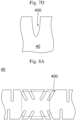
- the shape or the like of the notch 400 can be changed as appropriate (see FIGS. 7A to 7D ). Positions and intervals at which the notches 400 are formed, the number of notches 400 formed, and the size and the shape of the notch 400 are not particularly limited, and can be changed as appropriate in consideration of the rigidity and the heat dissipation performance of the body portion 40, a disposition relationship with the functional members, and the like. The above similarly applies to a case in which an opening or a slit is formed in the body portion 40.
- the memory is not particularly limited as long as the memory has a data storage area, and as hardware, the memory is configured as, for example, a flash memory chip.
- the memory may be a non-volatile rewritable memory, a non-rewritable memory that stores a program or the like, or a volatile memory for temporarily storing data.
- the functional members 3A to 3H are thus arranged such that the centers of gravity of the functional members 3A to 3H are arranged at intervals of 45 degrees in the circumferential direction of the tire 2 with reference to a central axis A1 of the tire 2 (for convenience of description, the positions of the centers of gravity of the functional members 3A to 3H are indicated by black dots in FIG. 1 ).
- each of the intervals with reference to the central axis A1 may include an error within ⁇ 10 degrees.
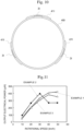
- FIGS. 12A and 12B Resultant graphs are shown in FIGS. 12A and 12B , which were obtained under respective conditions by plotting the output electrical power ( ⁇ W) of each electrical power generation device 3I with respect to the rotational speed (km/h) of the corresponding tire assembly.
- FIG. 12A is a graph under a condition in which the drum diameter was 500 mm, the wheel load was 2 kN, and the rotational speed was equivalent to 10 km/h to 50 km/h.
- FIG. 12B is a graph under a condition in which the drum diameter was 300 mm, the wheel load was 1 kN, and the rotational speed was equivalent to 30 km/h to 100 km/h.
- FIGS. 12A is a graph under a condition in which the drum diameter was 500 mm, the wheel load was 2 kN, and the rotational speed was equivalent to 10 km/h to 50 km/h.
- FIG. 12B is a graph under a condition in which the drum diameter was 300 mm, the wheel load was 1
Landscapes
- Engineering & Computer Science (AREA)
- Mechanical Engineering (AREA)
- Tires In General (AREA)
Abstract
Description
- The present invention relates to a tire assembly in which a functional member is incorporated inside a tire.
-
JP 2016-088473A JP 2016-088473A - According to
JP 2016-088473A - An object of the present invention is to provide a tire assembly that enables effective use of a functional member.
- A tire assembly according to a first aspect of the present invention includes a tire, a fixing member, and one or a plurality of functional members. The tire includes an attachment-receiving portion on an inside surface of the tire. The fixing member includes a body portion extending along a circumferential direction of the tire, and an attaching portion attachable to and detachable from the attachment-receiving portion. The one or plurality of functional members are configured to be fixed to the fixing member. The body portion includes at least one of metal, synthetic resin, or rubber.
- According to the tire assembly in accordance with the first aspect, the functional member is attachable to and detachable from the inside surface of the tire through the fixing member. Thus, it is possible to achieve reuse by detaching the fixing member including the functional member from the original tire.
- A tire assembly according to a second aspect of the present invention is the tire assembly according to the first aspect, wherein at least one of the one or plurality of functional members is disposed between the body portion and the inside surface.
- A tire assembly according to a third aspect of the present invention is the tire assembly according to the first aspect or the second aspect, wherein the body portion is formed in a ring shape extending along an entire circumference of the tire.
- A tire assembly according to a fourth aspect of the present invention is the tire assembly according to any of the first to third aspects, wherein a circumferential length of the body portion is equal to a circumferential length of the inside surface.
- A tire assembly according to a fifth aspect of the present invention is the tire assembly according to any of the first to fourth aspects, wherein the one or plurality of functional members are a plurality of functional members, and the plurality of functional members are provided. The plurality of functional members are arranged to cause total mass of the plurality of functional members to be distributed at equal intervals along the circumferential direction of the tire.
- According to the fifth aspect, since the mass balance of the tire assembly is maintained symmetrically with respect to the rotational axis, it is possible to reduce application of unnecessary vibration during the rotation of the tire assembly.
- A tire assembly according to a sixth aspect of the present invention is the tire assembly according to any of the first to fifth aspects, wherein the one or plurality of functional members are any of an electrical power generation device, a sensor device, a secondary battery, a capacitor, an antenna device, a transmitter, a processor, a memory, and a circuit.
- A tire assembly according to a seventh aspect of the present invention is the tire assembly according to any of the first to sixth aspects, wherein each of the attachment-receiving portion and the attaching portion includes a surface fastener.
- According to the seventh aspect, it is possible to easily attach and detach the functional member with a simple member.
- A tire assembly according to an eighth aspect of the present invention is the tire assembly according to the seventh aspect, wherein at least one of the one or plurality of functional members is disposed between the surface fastener and the body portion.
- According to the eighth aspect, it is possible to more reliably fix the functional member to the tire.
- A tire assembly according to a ninth aspect of the present invention is the tire assembly according to any of the first to eighth aspects, wherein at least one of the one or plurality of functional members is an electrical power generation device including a first member and a second member. The first member includes a first insulating film forming a first surface. The second member includes a second insulating film forming a second surface, and the second surface faces the first surface and is configured to come into contact with the first surface. The first member and the second member are configured to cause an area of real contact between the first surface and the second surface to change in accordance with pressure applied to the first member and the second member. The first insulating film and the second insulating film are configured to cause one of the first insulating film and the second insulating film to be positively charged and to cause the other one of the first insulating film and the second insulating film to be negatively charged, when the area of real contact is caused to change.
- When the tire assembly according to the ninth aspect is the tire assembly according to the eighth aspect, it is possible to further directly transmit deformation of the tire to the electrical power generation device, and it is possible to further increase the electrical power generation amount of the electrical power generation device. Further, it is possible to reduce a time during which the first surface and the second surface of the electrical power generation device are completely separated from each other due to the deformation of the tire. Accordingly, it is possible to further increase the total electrical power generation amount of the electrical power generation devices.
- A tire assembly according to a tenth aspect of the present invention is the tire assembly according to any of the first to ninth aspects, wherein one of the first member and the second member is fixed to the surface fastener, and the other one of the first member and the second member is fixed to the body portion.
- According to the tenth aspect, it is possible to more reliably fix the electrical power generation device to the tire. In addition, it is possible to reduce mutual displacement of positions of the first member and the second member.
- A tire assembly according to an eleventh aspect of the present invention is the tire assembly according to any of the first to tenth aspects, wherein at least one of an opening, a notch, or a slit is formed in the body portion.
- According to the eleventh aspect, it is possible to appropriately adjust the rigidity of the body portion, and it is possible to allow the body portion to easily follow deformation of the tire while maintaining strength necessary for the body portion.
- A tire assembly according to a twelfth aspect of the present invention is the tire assembly according to the eleventh aspect, wherein at least one of the notch or the slit extends along a direction intersecting the circumferential direction of the tire.
- A tire assembly according to a thirteenth aspect of the present invention is the tire assembly according to the fifth aspect, wherein at least one of the plurality of functional members is an electrical power generation device including a first member and a second member. The first member includes a first insulating film forming a first surface. The second member includes a second insulating film forming a second surface, and the second surface faces the first surface and is configured to come into contact with the first surface. The first member and the second member are configured to cause an area of real contact between the first surface and the second surface to change in accordance with pressure applied to the first member and the second member. The first insulating film and the second insulating film are configured to cause one of the first insulating film and the second insulating film to be positively charged and to cause the other one of the first insulating film and the second insulating film to be negatively charged, when the area of real contact is caused to change.
- A tire assembly according to a fourteenth aspect of the present invention is the tire assembly according to the first aspect, wherein the body portion is a strip-shaped member extending partially along the circumferential direction.
- A tire assembly according to a fifteenth aspect of the present invention is the tire assembly according to the fourteenth aspect, wherein each of the attachment-receiving portion and the attaching portion includes a surface fastener.
- A tire assembly according to a sixteenth aspect of the present invention is the tire assembly according to the fifteenth aspect, wherein the body portion includes a first body portion to which the attaching portion is fixed, the first body portion being disposed on an outer side in a radial direction of the tire, and a second body portion disposed on an inner side in the radial direction of the tire, and the one or plurality of functional members are disposed between the first body portion and the second body portion.
- A tire assembly according to a seventeenth aspect of the present invention is the tire assembly according to the sixteenth aspect, wherein a length of the attaching portion along the circumferential direction is longer than a length of the second body portion along the circumferential direction.
- A tire assembly according to an eighteenth aspect of the present invention is the tire assembly according to the seventeenth aspect, wherein a length of the attachment-receiving portion along the circumferential direction is longer than the length of the attaching portion along the circumferential direction.
- According to the eighteenth aspect, it is possible to easily attach and detach the fixing member. Further, it is possible to reduce the weight of the fixing member.
- According to the present invention, a tire assembly that enables effective use of a functional member is provided.
-
-
FIG. 1 is a perspective view showing an overall configuration of a tire assembly according to an embodiment; -
FIG. 2 is a longitudinal cross-sectional view of a tire; -
FIG. 3 is a perspective view showing an overall configuration of a fixing member according to the embodiment; -
FIG. 4 is a developed view of a body portion according to the embodiment; -
FIG. 5 is a view showing an example of an electrical power generation device; -
FIG. 6 is a longitudinal cross-sectional view of a tire assembly according to a variation; -
FIG. 7A is an enlarged view of a relevant part of a body portion according to a variation; -
FIG. 7B is an enlarged view of a relevant part of a body portion according to a variation; -
FIG. 7C is an enlarged view of a relevant part of a body portion according to a variation; -
FIG. 7D is an enlarged view of a relevant part of a body portion according to a variation; -
FIG. 8A is a plan view of a body portion according to a variation; -
FIG. 8B is a plan view of a body portion according to a variation; -
FIG. 8C is a plan view of a body portion according to a variation; -
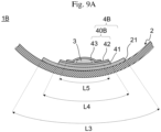
FIG. 9A is a side cross-sectional view of a tire assembly according to a variation; -
FIG. 9B is a developed view of the tire assembly according to the variation inFIG. 9A ; -
FIG. 10 is a schematic view of a fixing member according to examples; -
FIG. 11 is a graph showing an experiment result; -
FIG. 12A is a graph showing an experiment result; -
FIG. 12B is a graph showing an experiment result; and -
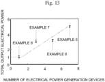
FIG. 13 is a graph showing an experiment result. - A tire assembly according to an embodiment of the present invention will be described below with reference to the drawings.
-
FIG. 1 is a perspective view showing an overall configuration of atire assembly 1 according to an embodiment of the present invention. Thetire assembly 1 is a tire product having an additional function such as a sensing function, an electrical power generation function, or a signal transmission function. Thetire assembly 1 is mounted on a wheel of each of various vehicles, and is configured to rotate on a road surface. As shown inFIG. 1 , thetire assembly 1 includes atire 2, a fixingmember 4, andfunctional members 3A to 3H. The fixingmember 4 extends along a circumferential direction of thetire 2, and can be detachably fixed to aninside surface 20 of thetire 2. Each of thefunctional members 3A to 3H is fixed to the fixingmember 4, and at least one of thefunctional members 3A to 3H is disposed between theinside surface 20 and an outercircumferential surface 40a of the fixingmember 4. Each member will be described below. -
FIG. 2 is a longitudinal cross-sectional view of the tire 2 (a cross-sectional view of a cross section along a radial direction of the tire assembly 1). Thetire 2 is formed of vulcanized rubber and the like, and has elasticity. The type and structure of thetire 2 are not particularly limited. Thetire 2 of the present embodiment includes atread portion 200,sidewall portions 201,shoulder portions 202, andbead portions 203, as shown inFIG. 2 . Thetread portion 200 is a portion that defines a side circumferential surface of thetire assembly 1, and is adapted to come into contact with the road surface to generate friction, thereby moving a vehicle forward. Thesidewall portions 201 are flexed in order to absorb a shock from the road surface, causing flexure. Theshoulder portions 202 are portions continuous with thetread portion 200 and thesidewall portions 201. Thebead portions 203 are portions fixed to a wheel rim, and include bead wires (not shown) embedded therein. Thetire 2 further includes theinside surface 20 that defines an inside space of thetire 2. An annular surface of theinside surface 20 corresponding to the back side of thetread portion 200 may be referred, below, to as aninside surface 20a to be distinguished from other portions of theinside surface 20. - The
tire 2 includes an attachment-receiving portion on theinside surface 20a for allowing attachment of the fixingmember 4. In the present embodiment, the attachment-receiving portion includes asurface fastener 21 extending along the circumferential direction of thetire 2. Thesurface fastener 21 is fixed on theinside surface 20a at a position corresponding to a position of asurface fastener 41 of the fixingmember 4 to be described later, and this allows the fixingmember 4 to be detachably fixed to theinside surface 20a. In the present embodiment, thesurface fastener 21 is fixed on theinside surface 20a so as to extend along the entire circumference of thetire 2. - The
surface fastener 21 and thesurface fastener 41 are not particularly limited as long as they are fasteners that are attachable and detachable using their surfaces. For example, one of the fasteners may include hook-shaped raised portions and the other fastener may include loop-shaped raised portions, each of the fasteners may include both hook-shaped raised portions and loop-shaped raised portions, or the fasteners may be coupled by being formed in other shapes. However, a material forming thesurface fastener 21 and thesurface fastener 41 preferably has heat resistance, in consideration of the inside environment of thetire 2. A method of attaching thesurface fastener 21 on theinside surface 20a is not particularly limited, and examples thereof include a method using an adhesive, and a method using a pressure-sensitive adhesive. -
FIG. 3 is a perspective view showing an overall configuration of the fixingmember 4 according to the present embodiment. The fixingmember 4 is a member for allowing the functional members, described later, to be attached to and detached from thetire 2, and includes abody portion 40 and an attaching portion. Thebody portion 40 is a portion extending along the circumferential direction of thetire 2. Thebody portion 40 can be formed of, for example, a thin strip-shaped member having a longer-side direction along the circumferential direction of thetire 2 and a width direction orthogonal to the longer-side direction. Thebody portion 40 may extend partially along the circumferential direction of thetire 2, or may extend along the entire circumference of thetire 2. Thebody portion 40 of the present embodiment extends along the entire circumference of thetire 2, and is formed in a ring shape by connecting both ends in the longer-side direction of thebody portion 40. When the circumferential length of theinside surface 20a is L2, the circumferential length L1 of the outercircumferential surface 40a of thebody portion 40 is preferably 0.98×L2 or more and 1.02×L2 or less, more preferably 0.99×L2 or more and 1.01×L2 or less, and still more preferably equal to L2 (the error is within ±0.5% of L2). - In the
body portion 40, as a type formed therein, at least one of an opening, a notch, or a slit is preferably formed, within a range allowing strength necessary for the fixingmember 4 to be maintained. Each of the opening and the notch can be formed by cutting out a part of a member forming thebody portion 40. The slit can be formed by making an incision inward from an outer edge of thebody portion 40. Two or more types of the opening, the notch, and the slit may be formed in thebody portion 40. The formation of at least one of the opening, the notch, or the slit in thebody portion 40 relaxes the rigidity of thebody portion 40 in the periphery thereof. As a result, thebody portion 40 easily follows deformation of thetire 2 due to air pressure or due to a shock. In particular, when the opening or the notch is formed, a surface area in a thickness direction of thebody portion 40 increases to improve the heat dissipation performance. Thus, this reduces an excessive increase in the temperature of thebody portion 40 due to heat or the like generated by running of thetire assembly 1, thereby reducing an influence on functions of thefunctional members 3Ato 3H. -
FIG. 4 is a developed view of thebody portion 40 according to the present embodiment. In this example,notches 400, which extend along the width direction of thebody portion 40, and which extend so as to intersect the circumferential direction of thetire 2, are formed in a staggered pattern in the width direction while being formed at regular intervals along the longer-side direction (in the drawing, the reference sign is assigned to only a representative one). As shown inFIG. 4 , thenotch 400 preferably has roundness (rounded shapes: R) at corners closer to the width-directional center C1. When the corner is not rounded, the vicinity of the corner is easily damaged if thebody portion 40 is deformed along with deformation of thetire 2 because stress concentrates on the corner. In contrast, when the corner is rounded, concentration of stress is reduced to reduce an occurrence of damage in thebody portion 40. However, as will be described later, the shape or the like of thenotch 400 can be changed as appropriate (seeFIGS. 7A to 7D ). Positions and intervals at which thenotches 400 are formed, the number ofnotches 400 formed, and the size and the shape of thenotch 400 are not particularly limited, and can be changed as appropriate in consideration of the rigidity and the heat dissipation performance of thebody portion 40, a disposition relationship with the functional members, and the like. The above similarly applies to a case in which an opening or a slit is formed in thebody portion 40. - Reference is made again to
FIG. 3 . At least one functional member is fixed on the outercircumferential surface 40a of thebody portion 40, whereby when the fixingmember 4 is attached to thetire 2, the at least one functional member is positioned and fixed between theinside surface 20a and the fixingmember 4. InFIG. 3 , for reference, positions at which thefunctional members 3A to 3H according to the present embodiment are fixed are indicated by dashed lines. In the present embodiment, the plurality offunctional members 3Ato 3H are fixed on the outercircumferential surface 40a so as to be arranged at equal intervals along the circumferential direction of thetire 2. The reason for arranging the plurality offunctional members 3A to 3H in this manner will be described later. Note that thefunctional members 3A to 3H may be undetachably fixed to thebody portion 40. - A material forming the
body portion 40 is not particularly limited, and can be, for example, a material including at least one of metal, synthetic resin, or rubber. However, examples of the synthetic resin and the rubber exclude a sponge material obtained by foaming the synthetic resin or the rubber, and a three-dimensional structural body formed by aggregating fibrous members including the synthetic resin or the rubber. Examples of types of the metal include stainless steel (SUS), carbon steel, aluminum, copper, brass, iron, and other types of metal such as alloy. These types of metal may be spring materials. Examples of the synthetic resin include polypropylene (PP), polyethylene (PE), engineering plastics such as polyethylene terephthalate (PET), polycarbonate (PC), and polyether ether ketone (PEEK), and fiber reinforced plastics (FRPs). - When the
body portion 40 is formed of stainless steel, the thickness of thebody portion 40 is preferably 0.3 mm or less, and more preferably 0.25 mm or less. When thebody portion 40 is formed of synthetic resin, the thickness of thebody portion 40 is preferably 0.5 mm or more and 3 mm or less. - The attaching portion is a portion that is attachable to and detachable from the attachment-receiving portion. In the present embodiment, the attaching portion includes the
surface fastener 41 that can be coupled to thesurface fastener 21, as described above. In the present embodiment, thesurface fastener 41 is fixed to thebody portion 40 so as to extend over the entire circumference of the outercircumferential surface 40a. Accordingly, when the fixingmember 4 is attached to thetire 2, it is not necessary to adjust positions of thesurface fastener 41 and thesurface fastener 21, thereby facilitating the attachment. In addition, when the functional members are disposed such that at least one of the functional members is sandwiched between the outercircumferential surface 40a and thesurface fastener 41, the functional member can be more firmly fixed to the fixingmember 4. - When the
body portion 40 has a ring shape, the mass of the fixingmember 4 including the attaching portion is preferably kept within a range in which running performance of thetire assembly 1 can be maintained, and is preferably, for example, 500 g or less although it depends on the size of thetire 2 or a material forming thebody portion 40. - The
tire assembly 1 includes one or a plurality of functional members fixed to the fixingmember 4. Thetire assembly 1 of the present embodiment includes the eightfunctional members 3A to 3H, but the number of functional members is not particularly limited. Regarding the functional members, at least one of the functional members is required to be disposed between thebody portion 40 and theinside surface 20a. In the present embodiment, sevenfunctional members 3A to 3G are electricalpower generation devices 3 to be described later, and are disposed between thebody portion 40 and theinside surface 20a. Onefunctional member 3H is a circuit to be described later, and is disposed on an inner circumferential surface of thebody portion 40. Each of thefunctional members 3A to 3G is fixed to at least one of the outercircumferential surface 40a or the back surface of a coupling surface of thesurface fastener 41. A method of fixing thefunctional members 3A to 3H is not particularly limited, and examples thereof include a method using an adhesive and a method using an adhesive tape. - The
functional members 3A to 3H may be any of an electrical power generation device, a sensor device, a secondary battery, a capacitor, an antenna device, a transmitter, a processor, a memory, and a circuit. That is, thefunctional members 3A to 3H may include two or more functional members of the same type, and are not necessarily required to include all types of the functional members described above. Each functional member will be described below. - The electrical power generation device is not particularly limited as long as the electrical power generation device generates electrical power using deformation of the
tire 2. The electrical power generation device may be a device using a piezoelectric element, a device for generating electrical power using contact charging, or the like. An example of the device for generating electrical power using contact charging is the electricalpower generation device 3 that includes a first surface formed of an insulating material and a second surface formed of an insulating material different from that of the first surface, and that generates an electrical potential difference due to a change in an area of real contact between the first surface and the second surface. Thetire assembly 1 preferably includes at least one electricalpower generation device 3 of this type. Details of the electricalpower generation device 3 will be described later. - When the
tire assembly 1 includes the secondary battery or the capacitor as another functional member, electricity generated in the electrical power generation device may be stored in the secondary battery or the capacitor. When thetire assembly 1 includes each of electronics such as the sensor device, the antenna device, the transmitter, the processor, or the memory as another functional member, electricity generated in the electrical power generation device may be appropriately supplied to these electronics. The electrical power generation device generates electrical power in conjunction with the rotation of thetire 2. Thus, by detecting a change in an electrical potential difference generated in the electrical power generation device, this also allows use as a sensor for monitoring at least one of a rotational speed of the tire, a wear state of the tire, a state of a road surface, or a ground-contact state. - The sensor device is not particularly limited as long as the sensor device acquires sensing data inside the
tire assembly 1, and may be, for example, an air pressure sensor, a temperature sensor, a speed sensor, an acceleration sensor, a rotational speed sensor, a rotational angle sensor, or the like. In a case where the sensor device is disposed between thetire 2 and the fixingmember 4, more accurate sensing data can be acquired as compared with that in a case where the sensor device is disposed on the inner side of the fixingmember 4. When thetire assembly 1 includes the processor as another functional member, the sensing data acquired by the sensor device may be processed by the processor to be processed data. When thetire assembly 1 includes the memory as another functional member, the sensing data acquired by the sensor device or the processed data thereof may be stored in the memory. When thetire assembly 1 includes the antenna device as another functional member, the sensing data acquired by the sensor device or the processed data thereof may be transmitted to a device outside thetire assembly 1, such as an in-vehicle device, via the antenna device. - The processor is not particularly limited as long as the processor, for example, executes a program, calculates, converts, processes, and transmits and receives data, and controls an operation of another functional member. As hardware, the processor is configured, for example, as an integrated circuit (IC) chip including a calculation unit, a register, a peripheral circuit, and the like. The processor may, for example, distribute electricity generated in the electrical power generation device, and receive data from an external device via the antenna device, in addition to generation of the processed data or transmission of the data, described above.
- The memory is not particularly limited as long as the memory has a data storage area, and as hardware, the memory is configured as, for example, a flash memory chip. The memory may be a non-volatile rewritable memory, a non-rewritable memory that stores a program or the like, or a volatile memory for temporarily storing data.
- The secondary battery is not particularly limited as long as the secondary battery is a battery that can be repeatedly used by charging. The secondary battery may be, for example, a lithium-ion battery, a lithium battery, an alkaline storage battery, a silver oxide-zinc storage battery, an all-solid-state battery, or the like. The secondary battery can be used to supply electricity to the electronics described above.
- The capacitor is not particularly limited, and any capacitor can be used. The capacitor may be used so as to store electricity generated in the electrical power generation device as necessary, or supply electricity to the electronics described above, and may also be used to maintain a constant voltage, or reduce noise.
- The antenna device is not particularly limited as long as the antenna device transmits and receives a radio wave, and any antenna device can be used. The antenna device may include a communication device for establishing wireless communication between the
tire assembly 1 and an external device of thetire assembly 1, in addition to an antenna itself that mutually converts a radio wave and an electrical current. - The transmitter is not particularly limited as long as the transmitter transmits a radio wave. The transmitter may be, for example, a Bluetooth (registered trademark) transmitter, a position information transmitter that transmits position information acquired from a satellite positioning system such as a global positioning system (GPS) to an external device, or the like.
- The circuit may be a circuit for operating another functional member or a circuit for operating other functional members in cooperation with each other, and the configuration thereof is not particularly limited. When the electrical power generation device is used as the sensor for monitoring at least one of the rotational speed of the tire, the wear state of the tire, the state of the road surface, or the ground-contact state, the circuit may be a measurement circuit for measuring a time-series voltage, electrical current, or electrical power generation amount of the electrical power generation device.
- At least some of the
functional members 3A to 3H may be electrically connected to each other by using lead wire or the like (not shown). However, from a viewpoint of reducing vibration and noise of thetire assembly 1, the mass of the lead wire or the like to be used is preferably sufficiently smaller than each of the respective masses of thefunctional members 3A to 3H. -
FIG. 5 is a cross-sectional view showing a configuration of the electricalpower generation device 3 according to the present embodiment. As shown inFIG. 5 , the electricalpower generation device 3 includes afirst member 31 and asecond member 32, and has a configuration in which the members are layered in this order. The electricalpower generation device 3 of the present embodiment has a rectangular shape in plan view, but the shape of the electricalpower generation device 3 is not limited to this shape. - The
first member 31 includes afirst substrate 312, afirst electrode 311, and a firstinsulating film 310. Each of these elements has a rectangular shape in plan view, and these elements are layered in this order from an outer side toward the inner side of the electricalpower generation device 3. Thefirst substrate 312 is formed of a flexible material or a viscoelastic material, such as resin or an elastomer, in order to be deformable by receiving an external force. A large number of recesses and protrusions are formed on a surface of thefirst substrate 312 on a side in contact with thefirst electrode 311. As a result, recesses and protrusions corresponding to the recesses and protrusions of thefirst substrate 312 are reproduced on afirst surface 3100 formed by the first insulatingfilm 310 through thefirst electrode 311. - The configuration of the recesses and protrusions of the
first substrate 312 is not particularly limited. For example, the recesses and protrusions may be formed in an orderly manner over a surface direction of thefirst substrate 312, or may be formed in a random manner to some extent. The cross-sectional shape of the recesses and protrusions is also not particularly limited. - The
first electrode 311 is a portion for extracting electrical charge generated in the first insulatingfilm 310 to the outside of the electricalpower generation device 3, and is disposed so as to be in contact with the first insulatingfilm 310 in the back side of thefirst surface 3100. Thefirst electrode 311 can be formed of a material having electrically conductive property, and examples of such a material include an electrically conductive film of Ag, Cu, or the like, and an electrically conductive cloth. The configuration of the electrically conductive cloth is not particularly limited, and the electrically conductive cloth may be an electrically conductive cloth formed by plating an organic fiber fabric formed of a polymer material with metal, an electrically conductive cloth formed by mixing fibers formed of a polymer material with metal fibers, or the like. Thefirst electrode 311 has flexibility, and can follow deformation of thefirst substrate 312 to be deformable. Thefirst electrode 311 reproduces the recesses and protrusions corresponding to the recesses and protrusions of thefirst substrate 312 on a surface of thefirst electrode 311 in contact with the first insulatingfilm 310. - The first
insulating film 310 is a film formed of an insulator, and has flexibility. In the present embodiment, a surface of the first insulatingfilm 310 opposite to thefirst electrode 311 corresponds to thefirst surface 3100. On thefirst surface 3100, the recesses and protrusions corresponding to the recesses and protrusions of thefirst substrate 312 are formed by thefirst substrate 312. Thefirst surface 3100 faces asecond surface 3200 formed by a secondinsulating film 320 to be described later, and is in contact with thesecond surface 3200. When an area of real contact or a real contact area, which is a substantive area of contact between thefirst surface 3100 and thesecond surface 3200, changes due to pressure applied to the electricalpower generation device 3, the first insulatingfilm 310 is charged to a polarity opposite to that of the secondinsulating film 320. That is, when the secondinsulating film 320 is positively charged, the first insulatingfilm 310 is negatively charged. When the secondinsulating film 320 is negatively charged, the first insulatingfilm 310 is positively charged. - The ten-point average roughness of the
first surface 3100 is preferably 100 µm or more and 2 mm or less. Note that the method of measuring the ten-point average roughness conforms to JIS B 0601: 2001. - A case where the
first surface 3100 and thesecond surface 3200 "come into contact" includes a case where thefirst surface 3100 and thesecond surface 3200 are partially in contact with each other and there is a portion in which thefirst surface 3100 and thesecond surface 3200 are not in contact with each other. The electricalpower generation device 3 of the present embodiment is configured such that both thefirst surface 3100 and thesecond surface 3200 have a rectangular shape and entirely overlap with each other. That is, in the electricalpower generation device 3 of the present embodiment, one surface of the first insulatingfilm 310 and one surface of the secondinsulating film 320 entirely come into contact with each other. - The
second member 32 includes asecond substrate 322, asecond electrode 321, and the secondinsulating film 320. Each element of thesecond member 32 has a rectangular shape in plan view, and the elements are layered in this order from an outer side toward the inner side of the electricalpower generation device 3. The configuration of thesecond substrate 322 and the configuration of thesecond electrode 321 are the same as the configuration of thefirst substrate 312 and the configuration of thefirst electrode 311, respectively, and thus the repeated description thereof will be omitted. - The second
insulating film 320 is a film formed of an insulator different from that of the first insulatingfilm 310, and has flexibility. In the present embodiment, a surface of the secondinsulating film 320 opposite to thesecond electrode 321 corresponds to thesecond surface 3200. On thesecond surface 3200, recesses and protrusions corresponding to recesses and protrusions of thesecond substrate 322 are formed by thesecond substrate 322. Thesecond surface 3200 faces thefirst surface 3100 formed by the first insulatingfilm 310, and is in contact with thefirst surface 3100. When the area of real contact described above changes due to the pressure applied to the electricalpower generation device 3, the secondinsulating film 320 is charged to a polarity opposite to that of the first insulatingfilm 310. - The ten-point average roughness of the
second surface 3200 is preferably 100 µm or more and 2 mm or less. Note that the method of measuring the ten-point average roughness conforms to JIS B 0601: 2001. - Each material forming a corresponding one of the first insulating
film 310 and the secondinsulating film 320 can be selected from the group consisting of, for example, diamond-like carbon (DLC), perfluoropolyether, polymethylmethacrylate, nylon, polyvinyl alcohol, polyester, polyisobutylene, polyurethane (PU), polyethylene terephthalate, polyvinyl butyral, polychloroprene, natural rubber, polyacrylonitrile, polycarbonate made from diphenyl carbonate, polyether chloride, polyvinylidene chloride, polystyrene, polyethylene, polypropylene, polyimide, polyvinyl chloride, polydimethylsiloxane, polytetrafluoroethylene, a tetrafluoroethylene and hexafluoropropylene copolymer, a tetrafluoroethylene-hexafluoropropylene copolymer (FEP), and another material containing a fluorocarbon organic substance as a main component. From a viewpoint of increasing the electromotive force of the electricalpower generation device 3, a pair of materials that are more distant from each other on the triboelectric series are preferably selected among the groups described above. - From a viewpoint of improving the electrical power generation amount of the electrical
power generation device 3, the electricalpower generation device 3 is preferably disposed between theinside surface 20a and thebody portion 40, and more preferably, the electricalpower generation device 3 is disposed between the outercircumferential surface 40a and thesurface fastener 41. As a result, it is possible to reduce positional displacement of thesecond member 32 in a surface direction with respect to thefirst member 31, and it is also possible to apply a force in a direction of pressing thefirst member 31 against thesecond member 32, thereby enabling facilitation of efficient electrical power generation. The orientation of the electricalpower generation device 3 in thetire assembly 1 is not particularly limited. Thefirst member 31 may be disposed on the outer side in the radial direction and thesecond member 32 may be disposed on the inner side in the radial direction, or thefirst member 31 may be disposed on the inner side in the radial direction and thesecond member 32 may be disposed on the outer side in the radial direction. That is, thefirst member 31 of the electricalpower generation device 3 may be fixed on the outercircumferential surface 40a while thesecond member 32 may be fixed on the back surface of thesurface fastener 41, or thefirst member 31 may be fixed on the back surface of thesurface fastener 41 while thesecond member 32 may be fixed on the outercircumferential surface 40a. - If mass balance along the circumferential direction of the tire is greatly lost by providing the functional members inside the tire, unnecessary vibration may occur along with the rotation of the tire to disturb comfortable traveling of the vehicle. Primary radial force variation (RFV) mainly contributes to this vibration. In the
tire assembly 1, in order to reduce the vibration due to the radial force variation, the functional members are preferably arranged such that the total mass of the functional members is distributed at equal intervals as much as possible, and as evenly as possible, along the circumferential direction of thetire 2. In the present embodiment, thefunctional members 3A to 3H are thus arranged such that the centers of gravity of thefunctional members 3A to 3H are arranged at intervals of 45 degrees in the circumferential direction of thetire 2 with reference to a central axis A1 of the tire 2 (for convenience of description, the positions of the centers of gravity of thefunctional members 3A to 3H are indicated by black dots inFIG. 1 ). However, each of the intervals with reference to the central axis A1 may include an error within ±10 degrees. That is, a case where the mass of the plurality of functional members is "distributed at equal intervals" along the circumferential direction of the tire includes a case where the centers of gravity of the functional members are arranged at intervals each including an error within ±10 degrees, in addition to a case where the centers of gravity of the functional members are arranged at intervals of even angles. - In addition, in order to distribute the total mass of the functional members as evenly as possible, a difference in mass between the functional members in the distributed arrangement is preferably reduced as smaller as possible. Further, in order to reduce the vibration of the
tire assembly 1 due to a higher-order component of the radial force variation, the mass itself of each of the functional members is preferably also small. Specifically, the mass of each functional member is preferably 40 g or less, more preferably 30 g or less, and still more preferably 20 g or less. - In the
tire assembly 1 of the present embodiment, thefunctional members 3A to 3H are detachably attached to thetire 2 through the fixingmember 4. As a result, even when replacement of thetire 2 is required, the fixingmember 4 and thefunctional members 3A to 3H can be reused for anew tire 2. Thus, it is possible to effectively use the resources. - In the
tire assembly 1 of the present embodiment, the fixingmember 4, accounting for a relatively large mass proportion in thetire assembly 1, is formed in a ring shape. Thus, the mass balance of thetire 2 is hardly lost, and the vibration due to the arrangement of thefunctional members 3A to 3H inside thetire 2 can be reduced. In addition, the attaching portion attached to thetire 2 is also formed in a ring shape. Thus, the vibration is further reduced, and attachment to thetire 2 and adjustment of the number of functional members are easily performed. Further, lightweight surface fasteners form the attachment-receiving portion and the attaching portion, and this reduces an adverse effect on the mass balance. In addition, in thetire assembly 1 of the present embodiment, the plurality offunctional members 3A to 3H are arranged at equal intervals along the circumferential direction of thetire 2, and the total mass of the plurality offunctional members 3Ato 3H is arranged so as to be evenly distributed (including a case of being substantially evenly distributed) along the circumferential direction of thetire 2. As a result, the mass imbalance caused by providing the functional members in thetire 2 is reduced, and occurrence of unnecessary vibration in thetire assembly 1 is reduced. - In the
tire assembly 1 of the present embodiment, thefunctional members 3A to 3G are accommodated between the outercircumferential surface 40a and thesurface fastener 41. As a result, thefunctional members 3Ato 3G are more reliably fixed by the fixingmember 4, and are less likely to fall off from the fixingmember 4. In addition, thefunctional members 3Ato 3G are the electricalpower generation devices 3, in the present embodiment. Thus, even when thefirst member 31 and thesecond member 32 of each of the electricalpower generation devices 3 are completely separated from each other, a force easily acts in a direction of pressing thefirst surface 3100 against thesecond surface 3200. Therefore, it is possible to reduce a time during which thefirst member 31 and thesecond member 32 are completely separated from each other, and it is possible to improve the electrical power generation amount of the electricalpower generation device 3. - In the
tire assembly 1 of the present embodiment, thenotches 400 are formed in thebody portion 40 of the fixingmember 4. This facilitates adjustment of the rigidity of thebody portion 40, and it is possible to improve performance to follow deformation of thetire 2. In addition, it is also possible to improve heat dissipation performance, and it is possible to reduce an undesirable influence on thefunctional members 3A to 3H due to heat along with running, or the like of thetire assembly 1. - Although an embodiment of the present invention has been described above, the present invention is not limited to the above embodiment, and various modifications can be made without departing from the gist of the present invention. The followings are examples of modifications that can be made. The spirits of the following variations can be combined as appropriate.
- (1) The
functional members 3A to 3H are simply required to be arranged such that the respective centers of gravity of thefunctional members 3A to 3H are distributed at equal intervals along the circumferential direction of thetire 2. Thus, as shown inFIG. 6 , the positions of the centers of gravity of the functional members along the width direction (direction parallel to the central axis A1) of thetire 2 may be different from each other. In addition, the number of functional members and the combination of functions can be changed as appropriate. - (2) The attachment-receiving portion of the
tire 2 and the attaching portion of the fixingmember 4 may include a member other than thesurface fastener 21 and a member other than thesurface fastener 41, respectively. In an example, the attachment-receiving portion and the attaching portion can include a pair of magnets, a pair formed of a magnet and a magnetic body, a pair of snap buttons, or the like. Another example may have the following configuration. That is, the attachment-receiving portion includes one or a plurality of protrusions protruding from theinside surface 20 toward the inside space, and the attaching portion includes one or a plurality of through-holes corresponding to the one or plurality of protrusions. Each of the one or plurality of protrusions is caused to pass through a corresponding one of the one or plurality of through-holes to fix the fixingmember 4 to thetire 2. Still another example may have the following configuration. That is, the attachment-receiving portion includes a plurality of recesses recessed from theinside surface 20 toward an inner portion of thetire 2, and the attaching portion includes a plurality of protrusions protruding outward in the radial direction from the outercircumferential surface 40a and having a shape fitted into the plurality of recesses. Each of the protrusions is fitted into a corresponding one of the recesses to fix the fixingmember 4 to thetire 2. In yet another example, one of the attachment-receiving portion and the attaching portion may include an adhesive tape that can be stuck again after being removed, and the other one may include a surface to which the adhesive tape is stuck. Alternatively, thesurface fastener 41 is not necessarily required to be continuous in a ring shape, and may be fixed to thebody portion 40 while being interrupted. Similarly, thesurface fastener 21 is not necessarily required to be continuous in a ring shape, and may be fixed to theinside surface 20a while being interrupted. In this case, two or more of the interruptedsurface fasteners 21 are preferably arranged so as to be distributed at equal intervals along the circumferential direction of thetire 2. - (3) The formation of the opening, the notch, and the slit may be omitted. In addition, as described above, the number, size, shape, interval, and position of the opening, the notch, and the slit can be set as appropriate. For example, the
notch 400 may have a shape (a rectangular shape, a wedge shape, a trapezoidal shape, or a U-shape) as shown inFIGS. 7A to 7D , and a tip thereof is not necessarily required to be reach the width-directional center C1 unlike the example ofFIG. 4 . Further, as shown inFIGS. 8A to 8C , the shapes, sizes, and intervals of thenotches 400 may be changed, or the formation of thenotch 400 may be omitted, in order to adjust the rigidity of thebody portion 40 at positions corresponding to the positions of thefunctional members 3A to 3H (the positions indicated by dashed lines). Further, thenotch 400 is not necessarily required to extend along the width direction, and is simply required to extend along a direction intersecting the longer-side direction (the circumferential direction of the tire 2). This similarly applies to a case in which a slit is formed in thebody portion 40. - (4) The fixing member (body portion) is not necessarily required to be formed in a ring shape, and may be formed as a strip-shaped member extending partially along the circumferential direction of the
tire 2. That is, the body portion may have a shape formed by dividing the ring by an appropriate length. In this case, thetire assembly 1 may include one or a plurality of fixing members. Alternatively, a plurality of functional members may be fixed to such a fixing member, or a single functional member may be fixed to such a fixing member. - (5)
FIG. 9A is a side cross-sectional view of atire assembly 1B according to a variation, andFIG. 9B is a developed view of thetire assembly 1B. In thetire assembly 1B, abody portion 40B of a fixingmember 4B is configured to sandwich and hold one or a plurality of functional members. More specifically, thebody portion 40B includes a strip-shapedfirst body portion 42 disposed on the outer side in the radial direction of thetire 2 and a strip-shapedsecond body portion 43 disposed on the inner side in the radial direction of thetire 2. In the example ofFIGS. 9A and9B , thefirst body portion 42 and thesecond body portion 43 are at least partially fixed at their outer edge portions such that a space is formed at the central portion. In the space, a single electricalpower generation device 3 is disposed so as to be sandwiched between thefirst body portion 42 and thesecond body portion 43. The electricalpower generation device 3 may be fixed to at least one of the side of thefirst body portion 42 or the side of thesecond body portion 43. Thefirst body portion 42 and thesecond body portion 43 can be formed of a material similar to that of thebody portion 40 of the above embodiment. However, from a viewpoint of weight reduction and easy processability of the fixingmember 4B, each of thefirst body portion 42 and thesecond body portion 43 is preferably formed of synthetic resin. Further, a strip-shapedsurface fastener 41, serving as an attaching portion, is fixed on one surface of thefirst body portion 42 so as to cover the entire one surface of thefirst body portion 42. Meanwhile, similarly to the above embodiment, asurface fastener 21, which can be coupled to thesurface fastener 41 as an attachment-receiving portion, is attached to the side of thetire 2 as the attachment-receiving portion. In the example ofFIGS. 9A and9B , thesurface fastener 21 has a strip shape, and extends partially along the circumferential direction of thetire 2. - In the above configuration, a length L3 of the
surface fastener 21 along the circumferential direction of thetire 2 is preferably longer than a length L4 of thesurface fastener 41 along the circumferential direction of thetire 2. Further, in the above configuration, the length L4 is preferably longer than a length L5 of thesecond body portion 43 along the circumferential direction of the tire 2 (note that the electricalpower generation device 3 is drawn in a magnified manner for its thickness inFIG. 9A ). That is, the relative relationship of the lengths is preferably L5<L4<L3. This configuration facilitates reduction in weight of the fixingmember 4B while facilitating attachment and detachment of the fixingmember 4B to and from thesurface fastener 21. However, the relative relationship of the lengths L3 to L5 is not limited to this, and may be, for example, L3=L4=L5, L5<L4=L3, or L5=L4<L3. The functional member may be a functional member other than the electricalpower generation device 3. - Experiments performed by the inventors and results thereof will be described below. However, the present invention is not limited to these experiments and results.
- Tire assemblies (Examples 1 to 3) were prepared, each of which included a tire with a heat-resistant surface fastener stuck on the entire circumference of the inside surface, a fixing member, and electrical power generation devices 3I each including a first member and a second member. The same tires (the entire circumference of its inside surface: 1600 mm) were used in Examples 1 and 2. In Example 1, a body portion 40I of the fixing member was formed so as to have the entire circumference (1610 mm) longer than the entire circumference of the inside surface of the tire by approximately 0.6%. In Example 2, the body portion 40I of the fixing member was formed so as to have the entire circumference (1580 mm) shorter than the entire circumference of the inside surface of the tire by approximately 1.25%. In the tire assembly of Example 3, the tire having a diameter smaller than those of Examples 1 and 2 was used, and the body portion 40I of the fixing member was formed so as to have the entire circumference substantially equal to the entire circumference of the inside surface of the tire. That is, in the respective tire assemblies of Examples 1 and 3, each of the fixing members was attached over the entire circumference of the inside surface of the corresponding tire without any gap. In contrast, in the tire assembly of Example 2, the fixing member was attached to the inside surface of the tire with an allowance being left.
- In each of Examples 1 to 3, the fixing member included a ring-shaped body portion 40I formed of polypropylene and three heat-resistant surface fasteners 41I fixed at substantially equal intervals on the outer circumferential surface of the body portion 40I. A large number of notches as shown in
FIG. 4 were formed in the body portion 40I. The mass of each fixing member was 200 g or less. The mass of each of the electrical power generation devices 3I was 10 g or less. As shown inFIG. 10 , each electrical power generation device 3I was fixed between a corresponding one of the surface fasteners 41I and the outer circumferential surface, and in total, three electrical power generation devices 3I were arranged at substantially equal intervals along the circumferential direction of the tire. The three electrical power generation devices 3I were connected to a voltage measurement device present at the outside, through lead wire (not shown). Each of the tire assemblies according to Examples 1 to 3 was attached to a wheel, was set to 250 kPa of air pressure, was mounted into a drum-type experiment device, was subjected to a wheel load of 2 kN, and was rotated at speed equivalent to 10 km/h to 50 km/h. - A resultant graph is shown in
FIG. 11 , which was obtained by plotting the total output electrical power (µW) of the electrical power generation devices 3I with respect to the rotational speeds (km/h) of the tire assemblies. As can be seen fromFIG. 11 , in a low-speed range (10 km/h to 30 km/h), the output electrical power of the tire assembly of Example 2 was the highest. However, in a speed range (40 km/h to 50 km/h) at which a vehicle normally travels, the output electrical power of the tire assemblies of Examples 1 and 3 became higher. From the result, when the tire assembly is mounted on a vehicle, it was confirmed to be more favorable to form the circumferential length of the fixing member equal to the circumferential length of the tire inside surface in terms of improving the electrical power generation amount. - A tire assembly according to Example 4 and a tire assembly according to Comparative Example 1 were prepared. The tire assembly according to Example 4 included a tire, a ring-shaped fixing member (expanded polypropylene, mass: 200 g), and a single electrical power generation device 3I. Respective heat-resistant surface fasteners were attached to the entire circumference of the inside surface of the tire and the entire circumference of the outer circumferential surface of the fixing member, and the fixing member was fixed to the tire by coupling these surface fasteners. The electrical power generation device 3I was attached between the outer circumferential surface of the fixing member and the surface fastener of the fixing member. The tire assembly according to Comparative Example 1 included a tire, a cover created from a tire repair patch (created by partially cutting off a portion of a patch MB-05 manufactured by Maruni Industry Co., Ltd. to have mass of approximately 60 g) for fixing a single electrical power generation device 3I, and the single electrical power generation device 3I. The tire was the same tire as that of Example 4, but the patch was attached at one position on the inside surface of the tire, instead of the surface fastener, and the electrical power generation device 3I was accommodated between the patch and the inside surface of the tire. Each of the tire assemblies according to Example 4 and Comparative Example 1 was attached to a wheel, was set to 250 kPa of air pressure, and was mounted into a corresponding one of two types of drum-type experiment devices having respective different drum diameters. Then, for each of the tire assemblies according to Example 4 and Comparative Example 1, the output electrical power (µW) of the electrical power generation device 3I was measured when the tire assembly was rotated while being subjected to a wheel load. The respective drum diameters of the drum-type experiment devices were 300 mm and 500 mm, the wheel load was 1 kN or 2 kN, and the rotational speed was equivalent to 30 km/h to 100 km/h or equivalent to 10 km/h to 50 km/h.
- Resultant graphs are shown in
FIGS. 12A and 12B , which were obtained under respective conditions by plotting the output electrical power (µW) of each electrical power generation device 3I with respect to the rotational speed (km/h) of the corresponding tire assembly.FIG. 12A is a graph under a condition in which the drum diameter was 500 mm, the wheel load was 2 kN, and the rotational speed was equivalent to 10 km/h to 50 km/h.FIG. 12B is a graph under a condition in which the drum diameter was 300 mm, the wheel load was 1 kN, and the rotational speed was equivalent to 30 km/h to 100 km/h. As can be seen fromFIGS. 12A and 12B , it was confirmed that, under both conditions, the output electrical power (µW) was improved at most rotational speeds in the tire assembly according to Example 4 as compared with the tire assembly according to Comparative Example 1. This is considered to be because a force of pressing a first surface against a second surface further acts in the electrical power generation device 3I due to the fixing member being formed in a ring shape. - A tire assembly including a tire, a fixing member, seven electrical power generation devices 3I, and a single measurement circuit, which were arranged as shown in
FIG. 1 , was prepared to obtain a tire assembly according to Example 5. The tire assembly was attached to a wheel, was set to 250 kPa of air pressure, was mounted into a drum-type experiment device, was subjected to a wheel load of 2 kN, and was rotated at speed equivalent to 50 km/h, and the total output electrical power (µW) of the electrical power generation devices 3I was measured. Next, two electrical power generation devices 3I arranged at positions corresponding to the positions of thefunctional members FIG. 1 were removed to form a tire assembly according to Example 6 by reducing the number of electrical power generation devices 3I to five. Then, the same kind of measurement was performed for the tire assembly according to Example 6. Further, two electrical power generation devices 3I arranged at positions corresponding to the positions of thefunctional members FIG. 1 were removed to form a tire assembly according to Example 7 by reducing the number of electrical power generation devices 3I to three. Then, the same kind of measurement was performed for the tire assembly according to Example 7. Finally, two electrical power generation devices 3I arranged at positions corresponding to the positions of thefunctional members FIG. 1 were removed to form a tire assembly according to Example 8 by reducing the number of electrical power generation devices 3I to one. Then, the same kind of measurement was performed for the tire assembly according to Example 8. - A resultant graph is shown in
FIG. 13 , which was obtained by plotting the total output electrical power, where the output electrical power of Example 8 is set to one, with respect to the number of electrical power generation devices 3I. FromFIG. 13 , it was confirmed that the output electrical power as the tire assembly increases in proportion to the number of electrical power generation devices 3I. -
- 1, 1B
- Tire assembly
- 2
- Tire
- 3, 3I
- Electrical power generation device
- 3A to 3H
- Functional member
- 4, 4B
- Fixing member
- 20, 20a
- Inside surface
- 21
- Surface fastener
- 31
- First member
- 32
- Second member
- 40, 40B, 40I
- Body portion
- 40a
- Outer circumferential surface
- 41
- Surface fastener
Claims (15)
- A tire assembly (1, 1B) comprising:a tire (2) including an attachment-receiving portion (21) on an inside surface (20, 20a) of the tire (2);a fixing member (4,4B) including a body portion (40, 40B, 40I) extending along a circumferential direction of the tire (2), and an attaching portion (41, 41I) attachable to and detachable from the attachment-receiving portion (21); andone or a plurality of functional members (3A, 3B, 3C, 3D, 3E, 3F, 3G, 3H) configured to be fixed to the fixing member (4,4B),wherein the body portion (40, 40B, 40I) includes at least one of metal, synthetic resin, or rubber.
- The tire assembly (1, 1B) according to claim 1,
wherein at least one of the one or plurality of functional members (3A, 3B, 3C, 3D, 3E, 3F, 3G, 3H) is disposed between the body portion (40, 40B, 40I) and the inside surface (20, 20a). - The tire assembly (1) according to claim 1 or 2,
wherein the body portion (40, 40I) is formed in a ring shape extending along an entire circumference of the tire (2). - The tire assembly (1, 1B) according to any one of claims 1 to 3,wherein the one or plurality of functional members (3A, 3B, 3C, 3D, 3E, 3F, 3G, 3H) comprise a plurality of functional members (3A, 3B, 3C, 3D, 3E, 3F, 3G, 3H), and the plurality of functional members (3A, 3B, 3C, 3D, 3E, 3F, 3G, 3H) are provided, andthe plurality of functional members (3A, 3B, 3C, 3D, 3E, 3F, 3G, 3H) are arranged to cause total mass of the plurality of functional members (3A, 3B, 3C, 3D, 3E, 3F, 3G, 3H) to be distributed at equal intervals along the circumferential direction of the tire (2).
- The tire assembly (1, 1B) according to any one of claims 1 to 4,
wherein each of the attachment-receiving portion (21) and the attaching portion (41, 41I) includes a surface fastener. - The tire assembly (1, 1B) according to claim 5,
wherein at least one of the one or plurality of functional members (3A, 3B, 3C, 3D, 3E, 3F, 3G, 3H) is disposed between the surface fastener and the body portion (40, 40B, 40I). - The tire assembly according to any one of claims 1 to 6,wherein at least one of the one or plurality of functional members (3A, 3B, 3C, 3D, 3E, 3F, 3G, 3H) is an electrical power generation device (3, 3I) including a first member (31) and a second member (32),the first member (31) includes a first insulating film (310) forming a first surface (3100),the second member (32) includes a second insulating film (320) forming a second surface (3200), the second surface (3200) facing the first surface (3100) and being configured to come into contact with the first surface (3100),the first member (31) and the second member (32) are configured to cause an area of real contact between the first surface (3100) and the second surface (3200) to change in accordance with pressure applied to the first member (31) and the second member (32), andthe first insulating film (310) and the second insulating film (320) are configured to cause one of the first insulating film (310) and the second insulating film (320) to be positively charged and to cause another one of the first insulating film (310) and the second insulating film (320) to be negatively charged, when the area of real contact is caused to change.
- The tire assembly (1, 1B) according to claim 7,wherein one of the first member (31) and the second member (32) is fixed to the surface fastener, andanother one of the first member (31) and the second member (32) is fixed to the body portion (40, 40B, 40I).
- The tire assembly (1, 1B) according to any one of claims 1 to 8,
wherein at least one of an opening, a notch (400), or a slit is formed in the body portion (40, 40B, 40I). - The tire assembly (1, 1B) according to one of claims 4 to 9,wherein at least one of the plurality of functional members (3A, 3B, 3C, 3D, 3E, 3F, 3G, 3H) is an electrical power generation device (3, 3I) including a first member (31) and a second member (32),the first member (31) includes a first insulating film (310) forming a first surface (3100),the second member (32) includes a second insulating film (320) forming a second surface (3200), the second surface (3200) facing the first surface (3100) and being configured to come into contact with the first surface (3100),the first member (31) and the second member (32) are configured to cause an area of real contact between the first surface (3100) and the second surface (3200) to change in accordance with pressure applied to the first member (31) and the second member (32), andthe first insulating film (310) and the second insulating film (320) are configured to cause one of the first insulating film (310) and the second insulating film (320) to be positively charged and to cause another one of the first insulating film (310) and the second insulating film (320) to be negatively charged, when the area of real contact is caused to change.
- The tire assembly (1B) according to one of claims 1 to 10,
wherein the body portion (40B) is a strip-shaped member extending partially along the circumferential direction. - The tire assembly (1B) according to claim 11,
wherein each of the attachment-receiving portion (21) and the attaching portion (41) includes a surface fastener. - The tire assembly (1B) according to claim 12,
wherein the body portion (40B) includes:a first body portion (42) to which the attaching portion (41) is fixed, the first body portion (42) being disposed on an outer side in a radial direction of the tire (2); anda second body portion (43) disposed on an inner side in the radial direction of the tire (2), andthe one or plurality of functional members (3A, 3B, 3C, 3D, 3E, 3F, 3G, 3H) are disposed between the first body portion (42) and the second body portion (43). - The tire assembly (1B) according to claim 13,
wherein a length of the attaching portion (41) along the circumferential direction is longer than a length of the second body portion (43) along the circumferential direction. - The tire assembly (1B) according to claim 14,
wherein a length of the attachment-receiving portion (21) along the circumferential direction is longer than the length of the attaching portion (41) along the circumferential direction.
Applications Claiming Priority (1)
| Application Number | Priority Date | Filing Date | Title |
|---|---|---|---|
| JP2022208698A JP2024092622A (en) | 2022-12-26 | 2022-12-26 | Tire Assembly |
Publications (1)
| Publication Number | Publication Date |
|---|---|
| EP4393731A1 true EP4393731A1 (en) | 2024-07-03 |
Family
ID=89121729
Family Applications (1)
| Application Number | Title | Priority Date | Filing Date |
|---|---|---|---|
| EP23214498.0A Withdrawn EP4393731A1 (en) | 2022-12-26 | 2023-12-06 | Tire assembly |
Country Status (4)
| Country | Link |
|---|---|
| US (1) | US20240208278A1 (en) |
| EP (1) | EP4393731A1 (en) |
| JP (1) | JP2024092622A (en) |
| CN (1) | CN118254507A (en) |
Citations (6)
| Publication number | Priority date | Publication date | Assignee | Title |
|---|---|---|---|---|
| FR2441502A1 (en) * | 1978-11-20 | 1980-06-13 | Pappas Dennis | Insufficient tyre pressure alarm device - has pressure sensor at each wheel transmitting to receiver in driver's cabin |
| EP1439079A2 (en) * | 2003-01-17 | 2004-07-21 | The Goodyear Tire & Rubber Company | Pneumatic tire having annular rubber strip containing electrically conductive element bonded to its inner surface |
| JP2016088473A (en) | 2014-11-11 | 2016-05-23 | 株式会社デンソー | Tire assembly |
| JP2017051024A (en) * | 2015-09-03 | 2017-03-09 | 三菱自動車工業株式会社 | Tire power generator |
| US20170141703A1 (en) * | 2015-11-13 | 2017-05-18 | Industry-Academic Cooperation Foundation, Yonam institute of Digital Technology | Generator for automobile using flexible piezoelectric device |
| WO2022180916A1 (en) * | 2021-02-26 | 2022-09-01 | 住友ゴム工業株式会社 | Tire assembly |
Family Cites Families (7)
| Publication number | Priority date | Publication date | Assignee | Title |
|---|---|---|---|---|
| JP3916625B2 (en) * | 2004-08-05 | 2007-05-16 | 横浜ゴム株式会社 | Pneumatic tire |
| US7770444B2 (en) * | 2005-12-13 | 2010-08-10 | Michelin Recherche Et Technique S.A. | Patch for fixing an electronic system to a tire |
| JP2009137497A (en) * | 2007-12-07 | 2009-06-25 | Bridgestone Corp | Electronic component mounting member and electronic component mounting method to tire inner surface |
| US20140261944A1 (en) * | 2013-03-15 | 2014-09-18 | The Goodyear Tire & Rubber Company | Encasing for releasably containing a device and tire containing such encasing or encased device |
| FR3029845B1 (en) * | 2014-12-15 | 2017-08-11 | Michelin & Cie | PATCH FOR ELECTRONIC PNEUMATIC MODULE |
| CN110733299A (en) * | 2018-07-18 | 2020-01-31 | 住友橡胶工业株式会社 | Tire assembly, monitoring system and method of tire |
| CN117882084A (en) * | 2021-08-30 | 2024-04-12 | 普利司通美国轮胎运营有限责任公司 | RFID package for tire |
-
2022
- 2022-12-26 JP JP2022208698A patent/JP2024092622A/en active Pending
-
2023
- 2023-11-28 CN CN202311609144.2A patent/CN118254507A/en active Pending
- 2023-12-06 EP EP23214498.0A patent/EP4393731A1/en not_active Withdrawn
- 2023-12-11 US US18/535,303 patent/US20240208278A1/en not_active Abandoned
Patent Citations (6)
| Publication number | Priority date | Publication date | Assignee | Title |
|---|---|---|---|---|
| FR2441502A1 (en) * | 1978-11-20 | 1980-06-13 | Pappas Dennis | Insufficient tyre pressure alarm device - has pressure sensor at each wheel transmitting to receiver in driver's cabin |
| EP1439079A2 (en) * | 2003-01-17 | 2004-07-21 | The Goodyear Tire & Rubber Company | Pneumatic tire having annular rubber strip containing electrically conductive element bonded to its inner surface |
| JP2016088473A (en) | 2014-11-11 | 2016-05-23 | 株式会社デンソー | Tire assembly |
| JP2017051024A (en) * | 2015-09-03 | 2017-03-09 | 三菱自動車工業株式会社 | Tire power generator |
| US20170141703A1 (en) * | 2015-11-13 | 2017-05-18 | Industry-Academic Cooperation Foundation, Yonam institute of Digital Technology | Generator for automobile using flexible piezoelectric device |
| WO2022180916A1 (en) * | 2021-02-26 | 2022-09-01 | 住友ゴム工業株式会社 | Tire assembly |
Also Published As
| Publication number | Publication date |
|---|---|
| US20240208278A1 (en) | 2024-06-27 |
| CN118254507A (en) | 2024-06-28 |
| JP2024092622A (en) | 2024-07-08 |
Similar Documents
| Publication | Publication Date | Title |
|---|---|---|
| EP1506101B1 (en) | System for generating electric power from a rotating tire's mechanical energy using reinforced piezoelectric materials | |
| JP4942984B2 (en) | System and method for generating electrical power from mechanical energy of a rotating tire | |
| US8387452B2 (en) | Method and system for generating electrical energy within a vehicle tyre | |
| US6807853B2 (en) | System and method for generating electric power from a rotating tire's mechanical energy using piezoelectric fiber composites | |
| JP5014590B2 (en) | System and method for generating electrical power from the mechanical energy of a rotating tire | |
| US20150020585A1 (en) | Tire module with piezo-electric transducer and tire equipped therewith | |
| CN112533777A (en) | Tyre comprising a monitoring device | |
| EP3603996A1 (en) | Functional component attachment base | |
| CN113165453A (en) | Tyre with monitoring device | |
| US20210257931A1 (en) | Power generation body | |
| EP4393731A1 (en) | Tire assembly | |
| US12558927B2 (en) | Elastic and power generation body assembly for a tire | |
| US20240410791A1 (en) | Tire state estimation method, and tire state estimation system | |
| CN114761260B (en) | Motorcycle tires including monitoring device | |
| EP3898291B1 (en) | Tyre comprising a monitoring device | |
| JP2026042530A (en) | Power generation module and tire assembly | |
| EP4393729A1 (en) | Tire assembly | |
| US20260042321A1 (en) | Tire with Treadwear Monitoring | |
| JP2014166820A (en) | Wear detection system, transmitter, tire and wheel | |
| JPWO2020235415A5 (en) | ||
| WO2020235415A1 (en) | Power source for tire monitoring system, tire monitoring system, and tire assembly |
Legal Events
| Date | Code | Title | Description |
|---|---|---|---|
| PUAI | Public reference made under article 153(3) epc to a published international application that has entered the european phase |
Free format text: ORIGINAL CODE: 0009012 |
|
| STAA | Information on the status of an ep patent application or granted ep patent |
Free format text: STATUS: THE APPLICATION HAS BEEN PUBLISHED |
|
| AK | Designated contracting states |
Kind code of ref document: A1 Designated state(s): AL AT BE BG CH CY CZ DE DK EE ES FI FR GB GR HR HU IE IS IT LI LT LU LV MC ME MK MT NL NO PL PT RO RS SE SI SK SM TR |
|
| STAA | Information on the status of an ep patent application or granted ep patent |
Free format text: STATUS: REQUEST FOR EXAMINATION WAS MADE |
|
| 17P | Request for examination filed |
Effective date: 20241129 |
|
| RBV | Designated contracting states (corrected) |
Designated state(s): AL AT BE BG CH CY CZ DE DK EE ES FI FR GB GR HR HU IE IS IT LI LT LU LV MC ME MK MT NL NO PL PT RO RS SE SI SK SM TR |
|
| P01 | Opt-out of the competence of the unified patent court (upc) registered |
Free format text: CASE NUMBER: APP_12391/2025 Effective date: 20250313 |
|
| STAA | Information on the status of an ep patent application or granted ep patent |
Free format text: STATUS: THE APPLICATION HAS BEEN WITHDRAWN |
|
| 18W | Application withdrawn |
Effective date: 20250523 |