EP4393629A1 - Ultrasonic welding device and electrode assembly manufactured thereby - Google Patents
Ultrasonic welding device and electrode assembly manufactured thereby Download PDFInfo
- Publication number
- EP4393629A1 EP4393629A1 EP22901622.5A EP22901622A EP4393629A1 EP 4393629 A1 EP4393629 A1 EP 4393629A1 EP 22901622 A EP22901622 A EP 22901622A EP 4393629 A1 EP4393629 A1 EP 4393629A1
- Authority
- EP
- European Patent Office
- Prior art keywords
- embo
- pair
- protrusion part
- electrode tabs
- electrode
- Prior art date
- Legal status (The legal status is an assumption and is not a legal conclusion. Google has not performed a legal analysis and makes no representation as to the accuracy of the status listed.)
- Granted
Links
Images



Classifications
-
- B—PERFORMING OPERATIONS; TRANSPORTING
- B23—MACHINE TOOLS; METAL-WORKING NOT OTHERWISE PROVIDED FOR
- B23K—SOLDERING OR UNSOLDERING; WELDING; CLADDING OR PLATING BY SOLDERING OR WELDING; CUTTING BY APPLYING HEAT LOCALLY, e.g. FLAME CUTTING; WORKING BY LASER BEAM
- B23K20/00—Non-electric welding by applying impact or other pressure, with or without the application of heat, e.g. cladding or plating
- B23K20/10—Non-electric welding by applying impact or other pressure, with or without the application of heat, e.g. cladding or plating making use of vibrations, e.g. ultrasonic welding
-
- B—PERFORMING OPERATIONS; TRANSPORTING
- B23—MACHINE TOOLS; METAL-WORKING NOT OTHERWISE PROVIDED FOR
- B23K—SOLDERING OR UNSOLDERING; WELDING; CLADDING OR PLATING BY SOLDERING OR WELDING; CUTTING BY APPLYING HEAT LOCALLY, e.g. FLAME CUTTING; WORKING BY LASER BEAM
- B23K20/00—Non-electric welding by applying impact or other pressure, with or without the application of heat, e.g. cladding or plating
- B23K20/10—Non-electric welding by applying impact or other pressure, with or without the application of heat, e.g. cladding or plating making use of vibrations, e.g. ultrasonic welding
- B23K20/106—Features related to sonotrodes
-
- H—ELECTRICITY
- H01—ELECTRIC ELEMENTS
- H01M—PROCESSES OR MEANS, e.g. BATTERIES, FOR THE DIRECT CONVERSION OF CHEMICAL ENERGY INTO ELECTRICAL ENERGY
- H01M50/00—Constructional details or processes of manufacture of the non-active parts of electrochemical cells other than fuel cells, e.g. hybrid cells
- H01M50/50—Current conducting connections for cells or batteries
- H01M50/531—Electrode connections inside a battery casing
- H01M50/536—Electrode connections inside a battery casing characterised by the method of fixing the leads to the electrodes, e.g. by welding
-
- H—ELECTRICITY
- H01—ELECTRIC ELEMENTS
- H01M—PROCESSES OR MEANS, e.g. BATTERIES, FOR THE DIRECT CONVERSION OF CHEMICAL ENERGY INTO ELECTRICAL ENERGY
- H01M50/00—Constructional details or processes of manufacture of the non-active parts of electrochemical cells other than fuel cells, e.g. hybrid cells
- H01M50/50—Current conducting connections for cells or batteries
- H01M50/531—Electrode connections inside a battery casing
- H01M50/538—Connection of several leads or tabs of wound or folded electrode stacks
-
- H—ELECTRICITY
- H01—ELECTRIC ELEMENTS
- H01M—PROCESSES OR MEANS, e.g. BATTERIES, FOR THE DIRECT CONVERSION OF CHEMICAL ENERGY INTO ELECTRICAL ENERGY
- H01M50/00—Constructional details or processes of manufacture of the non-active parts of electrochemical cells other than fuel cells, e.g. hybrid cells
- H01M50/50—Current conducting connections for cells or batteries
- H01M50/531—Electrode connections inside a battery casing
- H01M50/54—Connection of several leads or tabs of plate-like electrode stacks, e.g. electrode pole straps or bridges
-
- B—PERFORMING OPERATIONS; TRANSPORTING
- B23—MACHINE TOOLS; METAL-WORKING NOT OTHERWISE PROVIDED FOR
- B23K—SOLDERING OR UNSOLDERING; WELDING; CLADDING OR PLATING BY SOLDERING OR WELDING; CUTTING BY APPLYING HEAT LOCALLY, e.g. FLAME CUTTING; WORKING BY LASER BEAM
- B23K2101/00—Articles made by soldering, welding or cutting
- B23K2101/36—Electric or electronic devices
-
- Y—GENERAL TAGGING OF NEW TECHNOLOGICAL DEVELOPMENTS; GENERAL TAGGING OF CROSS-SECTIONAL TECHNOLOGIES SPANNING OVER SEVERAL SECTIONS OF THE IPC; TECHNICAL SUBJECTS COVERED BY FORMER USPC CROSS-REFERENCE ART COLLECTIONS [XRACs] AND DIGESTS
- Y02—TECHNOLOGIES OR APPLICATIONS FOR MITIGATION OR ADAPTATION AGAINST CLIMATE CHANGE
- Y02E—REDUCTION OF GREENHOUSE GAS [GHG] EMISSIONS, RELATED TO ENERGY GENERATION, TRANSMISSION OR DISTRIBUTION
- Y02E60/00—Enabling technologies; Technologies with a potential or indirect contribution to GHG emissions mitigation
- Y02E60/10—Energy storage using batteries
Definitions
- Secondary batteries are rechargeable unlike primarily batteries, and also, the possibility of compact size and high capacity is high. Thus, recently, many studies on secondary batteries are being carried out. As technology development and demands for mobile devices increase, the demands for secondary batteries as energy sources are rapidly increasing.
- the plurality of electrode tabs 13 connected to the positive electrode and the plurality of electrode tabs 13 connected to the negative electrode among the plurality of electrodes 12 may protrude in the same direction with respect to the electrode assembly 10 as illustrated in FIG. 3 .
- the present invention is not limited thereto, and the plurality of electrode tabs 13 connected to the positive electrode and the plurality of electrode tabs 13 connected to the negative electrode may protrude in directions opposite to each other with respect to the electrode assembly 10.
- a portion of the plurality of electrode tabs 13 may be welded to each other to form a welded portion 14.
- the plurality of electrode tabs 13 may get closer to each other toward the welded portion 14.
- a width of the welded portion 14 may be the same as that of the electrode tab 12.
- the welded portion 14 may be formed by the ultrasonic welding apparatus 100 described above.
- the length of each of the embo patterns 20 and 30 in the first direction may be less than a width w of the electrode tab 13. That is, the length L11 of the inner embo pattern 20 in the first direction may be less than the width w of the welded portion 14.
- the welded portion 14 may include a flat part 14a which is provided at each of both sides in the width direction and on which the inner embo pattern 20 and the pair of outer embo patterns 30 are not formed.
- the embo patterns 20 and 30 may not be formed on some of both sides of the welded portion 14 in the width direction. As a result, the embo patterns 20 and 30 may not invade both edges of the welded portion 14 in the width direction or may not be formed adjacent to both the edges of the welded portion 14 in the width direction, and thus, the risk of damage such as cracks or breakage at both the edges of the welded portion 14 in the width direction may be minimized.
Landscapes
- Chemical & Material Sciences (AREA)
- Chemical Kinetics & Catalysis (AREA)
- Electrochemistry (AREA)
- General Chemical & Material Sciences (AREA)
- Engineering & Computer Science (AREA)
- Mechanical Engineering (AREA)
- Connection Of Batteries Or Terminals (AREA)
- Secondary Cells (AREA)
- Pressure Welding/Diffusion-Bonding (AREA)
Abstract
Description
- The present application claims the benefit of the priority of
Korean Patent Application No. 10-2021-0169084, filed on November 30, 2021 - The present invention relates to an ultrasonic welding apparatus for welding a plurality of electrode tabs of an electrode assembly, and an electrode assembly manufactured by the ultrasonic welding apparatus.
- Secondary batteries are rechargeable unlike primarily batteries, and also, the possibility of compact size and high capacity is high. Thus, recently, many studies on secondary batteries are being carried out. As technology development and demands for mobile devices increase, the demands for secondary batteries as energy sources are rapidly increasing.
- Rechargeable batteries are classified into coin type batteries, cylindrical type batteries, prismatic type batteries, and pouch type batteries according to a shape of a battery case. In such a secondary battery, an electrode assembly mounted in a battery case is a chargeable and dischargeable power generating device having a structure in which an electrode and a separator are stacked.
- The electrode assembly may be approximately classified into a jelly-roll type electrode assembly in which a separator is interposed between a positive electrode and a negative electrode, each of which is provided as the form of a sheet coated with an active material, and then, the positive electrode, the separator, and the negative electrode are wound, a stacked type electrode assembly in which a plurality of electrodes with a separator therebetween are sequentially stacked, and a stack & folding type electrode assembly in which stacked type unit cells are wound together with a separation film having a long length.
- Particularly, each of the stack type or stack and folding type electrode assemblies includes the plurality of electrode tabs connected to the plurality of electrodes respectively, and the plurality of electrode tabs are generally welded to each other by an ultrasonic welding apparatus. However, since each of the plurality of electrode tabs has a thickness of several micrometers, an ultrasonically welded portion may be easily broken by disturbance or the like. Therefore, the ultrasonic welding apparatus for solving these concerns is required.
- One object of the present invention for solving this problem is to provide an ultrasonic welding apparatus that minimizes a risk of breakage or cracks occurring in a welded portion at which a plurality of electrode tabs are welded.
- Another object of the present invention for solving the above problem is to provide an electrode assembly manufactured by the ultrasonic welding apparatus.
- An ultrasonic welding apparatus may weld a plurality of electrode tabs of an electrode assembly to each other. The ultrasonic welding apparatus may include: an anvil disposed at one side of the plurality of electrode tabs; a horn disposed to face the anvil with the plurality of electrode tabs therebetween; and a protrusion part provided on at least one of the anvil and the horn to face the plurality of electrode tabs. The protrusion part may include: an inner protrusion part in which a plurality of first protrusions are arranged along a first direction parallel to a width direction of the electrode tabs; and a pair of outer protrusion parts which are disposed at both sides of the inner protrusion part in a second direction orthogonal to the first direction and in which a plurality of second protrusions are arranged at an interval wider than that between the plurality of first protrusions.
- A length of the protrusion part in the first direction may be less than a width of each of the plurality of electrode tabs.
- An interval between each of both ends of the protrusion part and each of both edges of each of the plurality of electrode tabs may be 1/45 to 1/30 of the width of each of the plurality of electrode tabs.
- A length of the inner protrusion part may be greater than that of each of the pair of outer protrusion parts in the first direction.
- The pair of outer protrusion parts may have a symmetrical shape with respect to the inner protrusion part.
- In the inner protrusion part, the plurality of first protrusions may be arranged along the first direction to form a plurality of columns.
- In each of the pair of outer protrusion parts, the plurality of second protrusions may be arranged along a virtual curve line.
- The curve line may form a portion of an ellipse.
- A distance between the inner protrusion part and each of the pair of outer protrusion parts in the second direction may gradually decrease outward in the first direction.
- A maximum distance between the inner protrusion part and each of the pair of outer protrusion parts in the second direction may be 0.5 times to 0.75 times a width of the inner protrusion part in the second direction.
- An electrode assembly may include: a plurality of electrodes stacked with a separator therebetween; a plurality of electrode tabs connected to the plurality of electrodes; and a welded portion, which is formed by welding the plurality of electrode tabs to each other. The welded portion may include: an inner embo pattern extending along a first direction parallel to a width direction of each of the plurality of electrode tabs; and a pair of outer embo patterns disposed at both sides of the inner embo pattern in a second direction orthogonal to the first direction and formed at an interval wider than that between the inner embo patterns.
- The welded portion may include a flat part which is provided at a portion of both sides in the width direction of each of the plurality of electrode tabs and on which the inner embo pattern and the pair of outer embo patterns are not formed.
- A width of the flat part may be 1/45 to 1/30 of a width of each of the plurality of electrode tabs.
- A length of the inner embo pattern may be greater than that of the outer embo pattern in the first direction.
- The pair of outer embo patterns may have a symmetrical shape with respect to the inner embo pattern.
- The inner embo pattern may form a plurality of columns in the first direction.
- The pair of outer embo patterns may be formed along a virtual curve line.
- The curve line may form a portion of an ellipse.
- A distance between the inner embo pattern and each of the pair of outer embo patterns in the second direction may gradually decrease outward in the first direction.
- A maximum distance between the inner embo pattern and the outer embo pattern in the second direction may be 0.5 times to 0.75 times a width of the inner embo pattern in the second direction.
- According to the preferred embodiment of the present invention, the distance between the plurality of second embossings provided in the outer embo pattern may be greater than that between the plurality of first embossings constituting the inner embo pattern. Thus, the possibility of breakage or cracks occurring at the welded boundary due to the disturbance may be reduced, and even though the breakage or cracks occurs, the expansion of the breakage or cracks may be minimized.
- In addition, the outer embo pattern may be formed along the curve line. Therefore, the possibility of breakage or cracks occurring at the welded boundary due to the disturbance may be more reduced, and even though the breakage or cracks occurs, the expansion of the breakage or cracks may be minimized.
- In addition, since the embo pattern is not formed on the portion of both the sides of the welded portion in the width direction, the risk of the breakage or cracks occurring at both the edges of the welded portion may be minimized.
- In addition, the effects that are obvious to those skilled in the art may be predicted from the configurations according to the embodiment of the present invention.
- The following drawings attached in this specification illustrate a preferred embodiment of the present invention and function to make further understood the technical spirit of the present invention along with the detailed description of the invention, and thus, the present invention should not be construed as being limited to only the drawings.
-
FIG. 1 is a schematic view of an ultrasonic welding apparatus according to an embodiment of the present invention. -
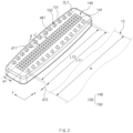
FIG. 2 is an enlarged view of a protrusion part according to an embodiment of the present invention. -
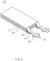
FIG. 3 is a perspective view of an electrode assembly according to another embodiment of the present invention. -
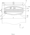
FIG. 4 is a plan view illustrating a welded portion of the electrode assembly according to another embodiment of the present invention. -
FIG. 5 is an enlarged view of a protrusion part according to a comparative example of the present invention. -
FIG. 6 is a plan view illustrating a welded of an electrode assembly according to the comparative example of the present invention. - Hereinafter, preferred embodiments of the present invention will be described in detail with reference to the accompanying drawings so that those of ordinary skill in the art can easily carry out the present invention. However, the present invention may be implemented in several different forms and is not limited or restricted by the following examples.
- In order to clearly explain the present invention, detailed descriptions of portions that are irrelevant to the description or related known technologies that may unnecessarily obscure the gist of the present invention have been omitted, and in the present specification, reference symbols are added to components in each drawing. In this case, the same or similar reference numerals are assigned to the same or similar elements throughout the specification.
- Also, terms or words used in this specification and claims should not be restrictively interpreted as ordinary meanings or dictionary-based meanings, but should be interpreted as meanings and concepts conforming to the scope of the present invention on the basis of the principle that an inventor can properly define the concept of a term to describe and explain his or her invention in the best ways.
-
FIG. 1 is a schematic view of an ultrasonic welding apparatus according to an embodiment of the present invention, andFIG. 2 is an enlarged view of a protrusion part according to an embodiment of the present invention. - The ultrasonic welding apparatus 100 (hereinafter, referred to as a welding apparatus) according to this embodiment may weld a plurality of
electrode tabs 13 of anelectrode assembly 10 to each other. Thewelding apparatus 100 may form a welded portion 14 (seeFIG. 3 , hereinafter, referred to as a welded portion) by welding the plurality ofelectrode tabs 13. That is, the weldedportion 14 may be a portion at which the plurality ofelectrode tabs 13 are welded to each other. - In more detail, the
welding apparatus 100 may include ananvil 110 disposed at one side of the plurality ofelectrode tabs 13, ahorn 120 facing theanvil 110 with the plurality ofelectrode tabs 13 therebetween, and aprotrusion part 130 provided on at least one of theanvil 110 or thehorn 120 to face the plurality ofelectrode tabs 13. - The
anvil 110 may be disposed below the plurality ofelectrode tabs 13, and thehorn 120 may be disposed above the plurality ofelectrode tabs 13. - A mutual distance of the
anvil 110 and thehorn 120 may be adjusted. For example, thehorn 120 may be configured so that the distance to theanvil 110 is adjustable. Thus, the plurality ofelectrode tabs 13 may be pressed between theanvil 110 and thehorn 120, and in this state, thehorn 120 may vibrate at a high frequency to weld the plurality ofelectrode tabs 13 to each other. In more detail, ultrasonic waves generated by a vibrator may be amplified by a booster and then transmitted to thehorn 120. Therefore, thehorn 120 may press the plurality ofelectrode tabs 13 disposed on theanvil 110 at a certain load and also apply the amplified ultrasonic waves transmitted from the booster to theelectrode tabs 13 to weld the plurality ofelectrode tabs 13 to each other. Since the configurations and operations of the ultrasonic vibrator and the booster are well-known, their detailed descriptions will be omitted. - The
protrusion part 130 may be provided on at least one of theanvil 110 or thehorn 120. Hereinafter, a case in which theprotrusion part 130 is provided on each of theanvil 110 and thehorn 120 will be described as an example. - Each of the
protrusion parts 130 may face the plurality ofelectrode tabs 13. In more detail, oneprotrusion part 130 may be provided on a bottom surface of theanvil 110, and theother protrusion part 130 may be provided on a bottom surface of thehorn 120. Theprotrusion part 130 provided on theanvil 110 may face the lower outermost electrode tab of the plurality ofelectrode tabs 13, and theprotrusion part 130 provided on thehorn 120 may face the upper outermost electrode tab of the plurality ofelectrode tabs 13. Theprotrusion part 130 provided on theanvil 110 may press the plurality ofelectrode tabs 13 at a lower side, and theprotrusion part 130 provided on thehorn 120 may press the plurality ofelectrode tabs 13 at an upper side. - The
protrusion part 130 may include a plurality ofprotrusions electrode tab 13. The plurality ofprotrusions first protrusions 141 provided in aninner protrusion part 140 to be described later and a plurality ofsecond protrusions 151 provided in anouter protrusion part 150 to be described later. Thefirst protrusion 141 and thesecond protrusion 151 may have the same size and shape, but are not limited thereto. - Each of the plurality of
first protrusions 141 and plurality ofsecond protrusions 151 may have a cross-sectional area that is gradually narrowed as it approaches theelectrode tab 13. For example, each of the plurality offirst protrusions 141 and the plurality ofsecond protrusions 151 may have a substantially polygonal pyramid shape. - A plurality of
embo patterns 20 and 30 (seeFIG. 4 ) corresponding to the plurality ofprotrusions FIG. 3 ) formed by welding theelectrode tabs 13. This will be described in detail later. - In more detail, the
protrusion part 130 may include theinner protrusion part 140 arranged along a first direction (a direction parallel to an x-axis ofFIG. 2 ) parallel to a width direction of theelectrode tab 13 and a pair ofouter protrusion parts 150 disposed at both sides of theinner protrusion 140 in a second direction (a direction parallel to a y-axis ofFIG. 2 ) and arranged at an interval wider than that between the plurality offirst protrusions 141. - The
inner protrusion part 140 may be formed by grouping the plurality offirst protrusions 141. Theinner protrusion part 140 may be arranged so that the plurality offirst protrusions 141 form at least one row in the first direction. Preferably, theinner protrusion part 140 may be arranged so that the plurality offirst protrusions 141 form a plurality of rows in the first direction. - The pair of
outer protrusion parts 150 may have a symmetrical shape with respect to theinner protrusion part 140. However, this embodiment is not limited thereto. - Each of the pair of
outer protrusion parts 150 may be formed by grouping the plurality ofsecond protrusions 151. In each of the outer pair ofprotrusion parts 150, the plurality ofsecond protrusions 151 may be arranged along a virtual curve line CL1. That is, each of the pair ofouter protrusion parts 150 may be formed along the curve line CL1. The curve line CL1 may form a portion of an ellipse. - The number of columns formed by the plurality of
second protrusions 151 may be less than the number of columns formed by the plurality offirst protrusions 141. For example, the plurality ofsecond protrusions 151 may be arranged along the curve line CL1 to form a single column, and the plurality offirst protrusions 141 may be arranged along the first direction to form a plurality of columns. - Since each of the pair of
outer protrusion parts 150 is formed along the curve line CL1, each of a pair of outer embo patterns 30 (seeFIG. 4 ) to be described later may also be formed along the curve line CL2. - A distance g between the plurality of
second protrusions 151 provided in the pair ofouter protrusion parts 150 may be wider than that between the plurality offirst protrusions 141 provided in theinner protrusion part 140. For example, the plurality offirst protrusions 141 may be disposed adjacent to each other without forming an interval, and an interval between the plurality ofsecond protrusions 151 may be greater than or equal to a width of each of thesecond protrusions 151. - In the first direction, a length L11 of the
inner protrusion part 140 may be longer than a length L12 of each of the pair ofouter protrusion parts 150. In the first direction, the length L11 of theinner protrusion part 140 may mean a length of theprotrusion part 130. - The length of the
protrusion part 130 in the first direction may be less than a width w of theelectrode tab 13. That is, the length L11 of theinner protrusion part 140 in the first direction may be less than the width w of theelectrode tab 13. - In more detail, a predetermined interval d12 may be formed between each of both ends of the
protrusion part 130 and each of both edges of theelectrode tab 13. An interval d12 may be 1/45 to 1/30 of the width w of theelectrode tab 13. For example, the width w of theelectrode tab 13 may be about 45 mm, and the interval d12 may be about 1 mm to about 1.5 mm. - As a result, while reliably welding the plurality of
electrode tabs 13, aflat part 14a on which theembo patterns FIG. 4 ) to be described later may be formed. - A distance d11 between the
inner protrusion part 140 and each of the pair ofouter protrusion parts 150 in the second direction may gradually decrease outward in the first direction. Thus, the distance d11 between theinner protrusion part 140 and each of the pair ofouter protrusion parts 150 in the second direction may be a maximum distance dm1 at a central portion of theprotrusion part 130 in the first direction. - The maximum distance dm1 between the
inner protrusion part 140 and each of the pair ofouter protrusion parts 150 in the second direction may be 0.5 times to 0.75 times the width w1 of theinner protrusion part 140 in the second direction. For example, the width w1 of theinner protrusion part 140 may be about 4 mm, and the maximum distance dm1 between theinner protrusion part 140 and each of the pair ofouter protrusion parts 150 may be about 2 mm to 3 mm. - As a result, while reliably welding the plurality of
electrode tabs 13, breakage or cracks that may occur in the welded portion 14 (seeFIG. 4 ) to be described later may be prevented from being expanded. -
FIG. 3 is a perspective view of an electrode assembly according to another embodiment of the present invention, andFIG. 4 is a plan view illustrating a welded portion of the electrode assembly according to another embodiment of the present invention. - Hereinafter, an
electrode assembly 10 manufactured by the above-describedultrasonic welding apparatus 100 will be described as another embodiment of the present invention. - The
electrode assembly 10 according to this embodiment may include a plurality ofelectrodes 11 stacked with aseparator 12 therebetween, a plurality ofelectrode tabs 13 connected to the plurality ofelectrodes 11, and a plurality of weldedportions 14, which are formed by welding the plurality ofelectrode tabs 13 to each other. - Each of the
electrodes 11 may be formed by applying active material slurry to an electrode collector in the form of a metal foil or a metal mesh. The plurality ofelectrodes 11 may be classified as positive electrodes or negative electrodes, Here, the positive electrode collector may include an aluminum material, and the negative electrode collector may include a copper material. The positive electrode and the negative electrode may be alternately stacked with theseparator 12 therebetween. - Each of the
electrode tab 13 may protrude from each of the plurality ofelectrodes 11 to act as a path through which electrons move between the inside and outside of theelectrode assembly 10 together with anelectrode lead 15. - The plurality of
electrode tabs 13 connected to the positive electrode and the plurality ofelectrode tabs 13 connected to the negative electrode among the plurality ofelectrodes 12 may protrude in the same direction with respect to theelectrode assembly 10 as illustrated inFIG. 3 . However, the present invention is not limited thereto, and the plurality ofelectrode tabs 13 connected to the positive electrode and the plurality ofelectrode tabs 13 connected to the negative electrode may protrude in directions opposite to each other with respect to theelectrode assembly 10. - A portion of the plurality of
electrode tabs 13 may be welded to each other to form a weldedportion 14. The plurality ofelectrode tabs 13 may get closer to each other toward the weldedportion 14. A width of the weldedportion 14 may be the same as that of theelectrode tab 12. The weldedportion 14 may be formed by theultrasonic welding apparatus 100 described above. - The plurality of
electrode tabs 13, more specifically, theelectrode lead 15 may be connected to the weldedportion 14 by spot welding or the like. When theelectrode assembly 10 is accommodated in a battery case (not shown), one end of theelectrode lead 15 may be connected to the plurality ofelectrode tabs 15, and the other end may protrude to the outside of the battery case. - A portion of the
electrode lead 15 may be surrounded by an insulatingpart 16. For example, the insulatingpart 16 may include an insulating tape. The insulatingpart 16 may prevent electricity generated in theelectrode assembly 10 from flowing to the battery case through theelectrode lead 15. Since this is a well-known technique, a detailed description thereof will be omitted. - Referring to
FIG. 4 ,embo patterns portion 14. Theembo patterns protrusion parts 130 of theultrasonic welding apparatus 10. The characteristics of theembo patterns protrusion parts 130 described above. - The
embo patterns embossings 21 and 31. The plurality ofembossings 21 and 31 include a plurality offirst embossings 21 provided in aninner embo pattern 20 to be described later and a plurality of second embossings 31 provided in a pair ofouter embo patterns 30 to be described later. Thefirst embossing 21 and the second embossing 31 may have the same size and shape, but are not limited thereto. - The
embo patterns inner embo pattern 20 formed by theinner protrusion part 140 of theultrasonic welding apparatus 10 and a pair ofouter embo pattern 30 formed by the pair ofouter protrusion parts 150 of theultrasonic welding apparatus 10. - Hereinafter, it will be described in more detail with reference to
FIGS. 2 and4 together. - The
inner embo pattern 20 extending along a first direction (a direction parallel to an x-axis ofFIG. 4 ) parallel to a width direction of theelectrode tab 13 and the pair ofouter embo patterns 30 disposed at both sides of theinner embo pattern 20 with respect to a second direction (a direction parallel to a y-axis ofFIG. 4 ) orthogonal to the first direction and formed at an interval wider than that between theinner embo pattern 20 may be formed on the weldedportion 14. - The
inner embo pattern 20 may be formed by grouping the plurality offirst embossings 21. Theinner embo pattern 20 may be arranged so that the plurality of firstembo patterns 21 form at least one row in the first direction. Preferably, theinner embo pattern 20 may be arranged so that the plurality of firstembo patterns 21 form a plurality of rows in the first direction. - The pair of
outer embo patterns 30 may have a symmetrical shape with respect to theinner embo pattern 20. However, this embodiment is not limited thereto. - The pair of
outer embo patterns 30 may form a welded boundary. - Each of the pair of
outer embo patterns 30 may be formed by grouping the plurality of second embossings 31. Each of the pair ofouter embo patterns 30 may be arranged so that the plurality of second embossings 31 are arranged along a virtual curve line CL2. That is, each of the pair ofouter embo patterns 30 may be formed along the curve line CL2. The curve line CL2 may form a portion of an ellipse. The curve line CL2 may correspond to a curve line CL1 formed by each of the pair ofouter protrusion parts 150 of theultrasonic welding apparatus 100. - The number of columns formed by the plurality of second embossings 31 may be less than the number of columns formed by the plurality of
first embossings 21. For example, the plurality of second embossings 31 may be arranged along the curve line CL2 to form a single column, and the plurality offirst embossings 21 may be arranged along the first direction to form a plurality of columns. - Since each of the pair of
outer embo pattern 30 is formed along the curve line CL2, the welded boundary may form the curve line. - An interval g2 between the plurality of second embossings 31 provided in each of the pair of
outer embo pattern 30 may be wider than an interval g1 between the plurality offirst embossings 21 provided in theinner embo pattern 20. - Thus, a risk of breakage or cracks occurring due to disturbance at the welded boundary may be reduced, and even if the breakage or cracks occur, expansion of the breakage or cracks may be restricted.
- In the first direction, a length L21 of the
inner embo pattern 20 may be longer than a length L22 of each of the pair ofouter embo pattern 30. The length L21 of theinner embo pattern 20 may be equal to or slightly shorter than a length L11 of theinner protrusion part 140 of theultrasonic welding apparatus 100. The length L22 of each of the pair ofouter embo patterns 30 may be equal to or slightly shorter than a length L12 of each of the pair ofouter protrusion parts 150 of theultrasonic welding apparatus 100. - In the first direction, the length L21 of the
inner embo pattern 20 may mean a length of each of theembo patterns - The length of each of the
embo patterns electrode tab 13. That is, the length L11 of theinner embo pattern 20 in the first direction may be less than the width w of the weldedportion 14. - The welded
portion 14 may include aflat part 14a which is provided at each of both sides in the width direction and on which theinner embo pattern 20 and the pair ofouter embo patterns 30 are not formed. Theembo patterns portion 14 in the width direction. As a result, theembo patterns portion 14 in the width direction or may not be formed adjacent to both the edges of the weldedportion 14 in the width direction, and thus, the risk of damage such as cracks or breakage at both the edges of the weldedportion 14 in the width direction may be minimized. - A width d22 of the
flat part 14a may be 1/45 to 1/30 of the width w of theelectrode tab 13, that is, the width w of the weldedportion 14. For example, the width w of theelectrode tab 13 may be about 45 mm, and the width d22 of theflat part 14a may be 1 mm to 1.5 mm. - As a result, while the welded
portion 14 is stably maintained, the risk of the damage such as the cracks or the breakages at both the edges of the weldedportion 14 in the width direction may be minimized. If the width d22 of theflat part 14a is less than 1/45 of the width w of theelectrode tab 13, each of theembo patterns portion 14 in the width direction, and thus, the risk of the damage such as the cracks or the breakage may occur at both the edges of the weldedportion 14 in the width direction. Conversely, when the width d22 of theflat part 14a exceeds 1/30 of the width w of theelectrode tab 13, welding force between the plurality ofelectrode tabs 13 may be weakened, and the weldedportion 14 may not be maintained stably. - A distance d21 between the
inner embo pattern 20 and each of the pair of theouter embo pattern 30 in the second direction may gradually decrease outward in the first direction. Therefore, the distance d21 between theinner embo pattern 20 and each of the pair ofouter embo patterns 30 in the second direction may be a maximum distance dm2 at a center of the weldedportion 14 in the first direction. - The maximum distance dm2 between the
inner embo pattern 20 and each of the pair ofouter embo patterns 30 in the second direction may be 0.5 times to 0.75 times the width w2 of theinner embo pattern 20 in the second direction. For example, the width w2 of theinner embo pattern 20 may be about 4 mm, and the maximum distance dm2 between theinner embo pattern 20 and each of the pair ofouter embo patterns 30 may be about 2 mm to 3 mm. - As a result, the welded
portion 14 may be stably maintained while restricting the expansion of the breakage or the cracks that may occur in theinner embo pattern 20. If the maximum distance dm2 is less than 0.5 times the width w2 of theinner embo pattern 20, since a line formed by each of the pair ofouter embo patterns 30 approaches a straight line rather than a curved line CL2, it may be difficult to exert the effect of restricting the expansion of the breakage or the cracks that may occur at theinner embo pattern 20. Conversely, when the maximum distance dm2 is greater than 0.75 times the width w2 of theinner embo pattern 20, an arrangement density per unit area of theembo patterns electrode tabs 13 may be weakened, and the weldedportion 14 may not be stably maintained. -
FIG. 5 is an enlarged view of a protrusion according to a comparative example of the present invention, andFIG. 6 is a plan view illustrating a welded portion of an electrode assembly according to the comparative example of the present invention. - Referring to
FIGS. 5 and6 , a length L of a protrusion part 130' according to a comparative example may be equal to or greater than a width w of a welded portion 14'. Thus, an embo pattern 20' formed on the welded portion 14' by the protrusion part 130' may invade or be adjacent to both edges of the welded portion 14' in a width direction. As a result, there is a high possibility that damage such as cracks or breakage may occur at both edges of the welded portion 14' in the width direction. - In addition, a plurality of protrusions 131' provided in the protrusion part 130' may be arranged at regular intervals. Therefore, a plurality of embossings 21' provided in the embo pattern 20' formed on the welded portion 14' may also be arranged at regular intervals, and the welded boundary may form a straight line.
- As a result, the breakage or cracks may easily occur at a boundary of the embo pattern 20', and there is a problem in that the breakage or the cracks are quickly expanded.
- According to this comparative example, those skilled in the art will be able to more easily understand the configuration and effect of the present invention.
- The above-disclosed subject matter is to be considered illustrative, and not restrictive, and the appended claims are intended to cover all such modifications, enhancements, and other embodiments, which fall within the true spirit and scope of the present disclosure.
- Thus, the embodiment of the present invention is to be considered illustrative, and not restrictive, and the technical spirit of the present invention is not limited to the foregoing embodiment.
- Therefore, the scope of the present disclosure is defined not by the detailed description of the invention but by the appended claims, and all differences within the scope will be construed as being included in the present disclosure.
-
- 10: Electrode assembly 11: Electrode
- 12: Separator 13: Electrode tab
- 14: Welded portion 15: Electrode lead
- 20: Inner embo pattern 21: First embossing
- 30: Outer embo pattern 31: Second embossing
- 100: Ultrasonic welding apparatus 110: Anvil
- 120: Horn 130: Protrusion part
- 140: Inner protrusion part 141: First protrusion
- 150: Outer protrusion part 151: Second protrusion
Claims (20)
- An ultrasonic welding apparatus, which welds a plurality of electrode tabs of an electrode assembly to each other, the ultrasonic welding apparatus comprising:an anvil disposed at one side of the plurality of electrode tabs;a horn disposed to face the anvil with the plurality of electrode tabs therebetween; anda protrusion part provided on at least one of the anvil and the horn to face the plurality of electrode tabs,wherein the protrusion part comprises:an inner protrusion part in which a plurality of first protrusions are arranged along a first direction parallel to a width direction of the electrode tabs; anda pair of outer protrusion parts which are disposed at both sides of the inner protrusion part in a second direction orthogonal to the first direction and in which a plurality of second protrusions are arranged an interval wider than that between the plurality of first protrusions.
- The ultrasonic welding apparatus of claim 1, wherein a length of the protrusion part in the first direction is less than a width of each of the plurality of electrode tabs.
- The ultrasonic welding apparatus of claim 2, wherein an interval between each of both ends of the protrusion part and each of both edges of each of the plurality of electrode tabs is 1/45 to 1/30 of the width of each of the plurality of electrode tabs.
- The ultrasonic welding apparatus of claim 1, wherein a length of the inner protrusion part is greater than that of each of the pair of outer protrusion parts in the first direction.
- The ultrasonic welding apparatus of claim 1, wherein the pair of outer protrusion parts have a symmetrical shape with respect to the inner protrusion part.
- The ultrasonic welding apparatus of claim 1, wherein, in the inner protrusion part, the plurality of first protrusions are arranged along the first direction to form a plurality of columns.
- The ultrasonic welding apparatus of claim 1, wherein, in each of the pair of outer protrusion parts, the plurality of second protrusions are arranged along a virtual curve line.
- The ultrasonic welding apparatus of claim 7, wherein the curve line forms a portion of an ellipse.
- The ultrasonic welding apparatus of claim 1, wherein a distance between the inner protrusion part and each of the pair of outer protrusion parts in the second direction gradually decreases outward in the first direction.
- The ultrasonic welding apparatus of claim 9, wherein a maximum distance between the inner protrusion part and each of the pair of outer protrusion parts in the second direction is 0.5 times to 0.75 times a width of the inner protrusion part in the second direction.
- An electrode assembly comprising:a plurality of electrodes stacked with a separator therebetween;a plurality of electrode tabs connected to the plurality of electrodes; anda welded portion, which is formed by welding the plurality of electrode tabs to each other,wherein the welded portion comprises:an inner embo pattern extending along a first direction parallel to a width direction of each of the plurality of electrode tabs; anda pair of outer embo patterns disposed at both sides of the inner embo pattern in a second direction orthogonal to the first direction and formed at an interval wider than that between the inner embo patterns.
- The electrode assembly of claim 11, wherein the welded portion comprises a flat part which is provided at a portion of both sides in the width direction of each of the plurality of electrode tabs and on which the inner embo pattern and the pair of outer embo pattern are not formed.
- The electrode assembly of claim 12, wherein a width of the flat part is 1/45 to 1/30 of a width of each of the plurality of electrode tabs.
- The electrode assembly of claim 11, wherein a length of the inner embo pattern is greater than that of each of the pair of outer embo pattern in the first direction.
- The electrode assembly of claim 11, wherein the pair of outer embo patterns have a symmetrical shape with respect to the inner embo pattern.
- The electrode assembly of claim 11, wherein the inner embo pattern forms a plurality of columns in the first direction.
- The electrode assembly of claim 11, wherein the pair of outer embo patterns are formed along a virtual curve line.
- The electrode assembly of claim 17, wherein the curve line forms a portion of an ellipse.
- The electrode assembly of claim 11, wherein a distance between the inner embo pattern and each of the pair of outer embo patterns in the second direction gradually decreases outward in the first direction.
- The electrode assembly of claim 19, wherein a maximum distance between the inner embo pattern and each of the pair of outer embo patterns in the second direction is 0.5 times to 0.75 times a width of the inner embo pattern in the second direction.
Applications Claiming Priority (2)
| Application Number | Priority Date | Filing Date | Title |
|---|---|---|---|
| KR1020210169084A KR102832841B1 (en) | 2021-11-30 | 2021-11-30 | Ultrasonic welding apparatus and electrode assembly manufactured by the same |
| PCT/KR2022/018000 WO2023101264A1 (en) | 2021-11-30 | 2022-11-15 | Ultrasonic welding device and electrode assembly manufactured thereby |
Publications (3)
| Publication Number | Publication Date |
|---|---|
| EP4393629A1 true EP4393629A1 (en) | 2024-07-03 |
| EP4393629A4 EP4393629A4 (en) | 2025-01-01 |
| EP4393629B1 EP4393629B1 (en) | 2025-09-10 |
Family
ID=86612736
Family Applications (1)
| Application Number | Title | Priority Date | Filing Date |
|---|---|---|---|
| EP22901622.5A Active EP4393629B1 (en) | 2021-11-30 | 2022-11-15 | Ultrasonic welding apparatus and electrode assembly manufactured thereby |
Country Status (8)
| Country | Link |
|---|---|
| US (1) | US20240408694A1 (en) |
| EP (1) | EP4393629B1 (en) |
| JP (1) | JP7782121B2 (en) |
| KR (1) | KR102832841B1 (en) |
| CN (1) | CN118103171A (en) |
| ES (1) | ES3043891T3 (en) |
| HU (1) | HUE073322T2 (en) |
| WO (1) | WO2023101264A1 (en) |
Families Citing this family (2)
| Publication number | Priority date | Publication date | Assignee | Title |
|---|---|---|---|---|
| KR20250034766A (en) | 2023-09-04 | 2025-03-11 | 에스케이온 주식회사 | Welding device, Welding method, and Electrode assembly |
| KR20260039402A (en) * | 2024-09-13 | 2026-03-20 | 삼성에스디아이 주식회사 | Welding equipment and electrode manufacturing method using the same |
Family Cites Families (15)
| Publication number | Priority date | Publication date | Assignee | Title |
|---|---|---|---|---|
| JP4013691B2 (en) * | 2002-07-31 | 2007-11-28 | 住友電装株式会社 | Flexible flat cable connection method and ultrasonic welding machine |
| CN100522449C (en) * | 2005-01-28 | 2009-08-05 | 日产自动车株式会社 | Ultrasonic bonding equipment and resulting bonding structure |
| JP4792945B2 (en) * | 2005-01-28 | 2011-10-12 | 日産自動車株式会社 | Ultrasonic bonding apparatus and bonded structure |
| JP4609169B2 (en) * | 2005-04-15 | 2011-01-12 | 日産自動車株式会社 | Ultrasonic bonding method |
| JP2007330851A (en) * | 2006-06-12 | 2007-12-27 | Toyota Motor Corp | Ultrasonic bonding horn, ultrasonic bonding apparatus and ultrasonic bonding method |
| WO2013105361A1 (en) * | 2012-01-12 | 2013-07-18 | 日立マクセル株式会社 | Ultrasonic welding tip, ultrasonic welding machine, and method for producing battery |
| KR20140022690A (en) * | 2012-08-14 | 2014-02-25 | 주식회사 엘지화학 | Ultrasonic welding ultrasonic sonotrode horn and welding assembly using the same |
| JP2014212012A (en) * | 2013-04-18 | 2014-11-13 | トヨタ自動車株式会社 | Method of manufacturing secondary battery and secondary battery |
| JP6856024B2 (en) * | 2015-09-29 | 2021-04-07 | 株式会社Gsユアサ | Power storage element and manufacturing method of power storage element |
| JP2018156841A (en) * | 2017-03-17 | 2018-10-04 | パナソニックIpマネジメント株式会社 | Electrode bonding structure |
| KR102444273B1 (en) * | 2017-04-25 | 2022-09-15 | 삼성에스디아이 주식회사 | Rechargeable battery |
| JP6868704B2 (en) * | 2017-10-02 | 2021-05-12 | ビークルエナジージャパン株式会社 | Secondary battery |
| JP7219495B2 (en) * | 2018-09-28 | 2023-02-08 | 株式会社Link-Us | Ultrasonic bonding equipment |
| DE102018221843A1 (en) * | 2018-12-14 | 2020-06-18 | Volkswagen Aktiengesellschaft | Ultrasonic welding device and method for producing a metal foil stack |
| KR102323041B1 (en) * | 2019-02-01 | 2021-11-08 | 주식회사 엘지에너지솔루션 | Electrode Assembly Comprising Different Pressure Welded Part on Weld Surface of Electrode Tab and Ultrasonic Welding Device for Manufacturing the Same |
-
2021
- 2021-11-30 KR KR1020210169084A patent/KR102832841B1/en active Active
-
2022
- 2022-11-15 US US18/699,737 patent/US20240408694A1/en active Pending
- 2022-11-15 ES ES22901622T patent/ES3043891T3/en active Active
- 2022-11-15 JP JP2024528564A patent/JP7782121B2/en active Active
- 2022-11-15 HU HUE22901622A patent/HUE073322T2/en unknown
- 2022-11-15 CN CN202280066041.3A patent/CN118103171A/en active Pending
- 2022-11-15 EP EP22901622.5A patent/EP4393629B1/en active Active
- 2022-11-15 WO PCT/KR2022/018000 patent/WO2023101264A1/en not_active Ceased
Also Published As
| Publication number | Publication date |
|---|---|
| US20240408694A1 (en) | 2024-12-12 |
| JP2024541375A (en) | 2024-11-08 |
| EP4393629B1 (en) | 2025-09-10 |
| KR102832841B1 (en) | 2025-07-10 |
| WO2023101264A1 (en) | 2023-06-08 |
| HUE073322T2 (en) | 2026-01-28 |
| KR20230081222A (en) | 2023-06-07 |
| ES3043891T3 (en) | 2025-11-26 |
| JP7782121B2 (en) | 2025-12-09 |
| EP4393629A4 (en) | 2025-01-01 |
| CN118103171A (en) | 2024-05-28 |
Similar Documents
| Publication | Publication Date | Title |
|---|---|---|
| KR102920238B1 (en) | Secondary battery improved collecting structure | |
| KR100599749B1 (en) | Secondary Battery and Electrode Assembly Used in the Same | |
| CN110326130B (en) | Electrode with improved electrode tab welding characteristics and secondary battery including the same | |
| EP3933964B1 (en) | Apparatus for manufacturing electrode for a secondary battery | |
| EP4393629B1 (en) | Ultrasonic welding apparatus and electrode assembly manufactured thereby | |
| US20250153262A1 (en) | Welding Apparatus and Welding Method | |
| EP3849004A1 (en) | Secondary battery | |
| US20120164520A1 (en) | Electrode Assembly and Secondary Battery Including Electrode Assembly | |
| CN108140872A (en) | Electrode assembly comprising electrode plates having interconnected additional tabs formed thereon | |
| EP4631664A1 (en) | Ultrasonic welding device and welded structure | |
| KR20230057957A (en) | Secondary battery, manufacturing method of the secondary battery and degas apparatus used in the same | |
| US20230071671A1 (en) | Electrode assembly and manufacturing method of the same | |
| US20240356086A1 (en) | Separator Stack, Electrode Assembly Including Same, and Electrode Assembly Manufacturing Method | |
| KR101765780B1 (en) | Battery having Cell Tab Connecting Structure using Ultrasonic Welding | |
| US20260031383A1 (en) | Apparatus for Manufacturing Secondary Battery, Method for Manufacturing Secondary Battery Using the Same, and Secondary Battery Manufactured Using the Same | |
| EP4560823B1 (en) | Apparatus for manufacturing secondary battery, method for manufacturing secondary battery using the same, and secondary battery manufactured using the same | |
| KR20240104891A (en) | Ultrasonic welding device | |
| EP4579891A1 (en) | Secondary battery, manufacturing method for same secondary battery, and pressing device used for same manufacturing method | |
| EP4654371A1 (en) | Cylindrical secondary battery and method for manufacturing cylindrical secondary battery | |
| CN112074967A (en) | Electrochemical cell | |
| JP2025527868A (en) | electrode assembly | |
| JP2025504161A (en) | Electrode cutting device and method | |
| KR20260065670A (en) | Electrode Cutting Device With Improved Electrode Tab Detection Capability And Electrode Cutting Method Thereof | |
| JP2025534527A (en) | electrode assembly | |
| CN121620838A (en) | Electrode assembly, secondary battery including the same, and method of manufacturing the same |
Legal Events
| Date | Code | Title | Description |
|---|---|---|---|
| STAA | Information on the status of an ep patent application or granted ep patent |
Free format text: STATUS: THE INTERNATIONAL PUBLICATION HAS BEEN MADE |
|
| PUAI | Public reference made under article 153(3) epc to a published international application that has entered the european phase |
Free format text: ORIGINAL CODE: 0009012 |
|
| STAA | Information on the status of an ep patent application or granted ep patent |
Free format text: STATUS: REQUEST FOR EXAMINATION WAS MADE |
|
| 17P | Request for examination filed |
Effective date: 20240325 |
|
| AK | Designated contracting states |
Kind code of ref document: A1 Designated state(s): AL AT BE BG CH CY CZ DE DK EE ES FI FR GB GR HR HU IE IS IT LI LT LU LV MC ME MK MT NL NO PL PT RO RS SE SI SK SM TR |
|
| A4 | Supplementary search report drawn up and despatched |
Effective date: 20241204 |
|
| RIC1 | Information provided on ipc code assigned before grant |
Ipc: H01M 50/538 20210101ALI20241128BHEP Ipc: H01M 50/536 20210101ALI20241128BHEP Ipc: B23K 101/36 20060101ALI20241128BHEP Ipc: H01M 50/54 20210101ALI20241128BHEP Ipc: B23K 20/10 20060101AFI20241128BHEP |
|
| DAV | Request for validation of the european patent (deleted) | ||
| DAX | Request for extension of the european patent (deleted) | ||
| GRAP | Despatch of communication of intention to grant a patent |
Free format text: ORIGINAL CODE: EPIDOSNIGR1 |
|
| STAA | Information on the status of an ep patent application or granted ep patent |
Free format text: STATUS: GRANT OF PATENT IS INTENDED |
|
| RIC1 | Information provided on ipc code assigned before grant |
Ipc: B23K 20/10 20060101AFI20250612BHEP Ipc: H01M 50/54 20210101ALI20250612BHEP Ipc: B23K 101/36 20060101ALI20250612BHEP Ipc: H01M 50/536 20210101ALI20250612BHEP Ipc: H01M 50/538 20210101ALI20250612BHEP |
|
| GRAS | Grant fee paid |
Free format text: ORIGINAL CODE: EPIDOSNIGR3 |
|
| INTG | Intention to grant announced |
Effective date: 20250630 |
|
| P01 | Opt-out of the competence of the unified patent court (upc) registered |
Free format text: CASE NUMBER: APP_31608/2025 Effective date: 20250701 |
|
| GRAA | (expected) grant |
Free format text: ORIGINAL CODE: 0009210 |
|
| STAA | Information on the status of an ep patent application or granted ep patent |
Free format text: STATUS: THE PATENT HAS BEEN GRANTED |
|
| AK | Designated contracting states |
Kind code of ref document: B1 Designated state(s): AL AT BE BG CH CY CZ DE DK EE ES FI FR GB GR HR HU IE IS IT LI LT LU LV MC ME MK MT NL NO PL PT RO RS SE SI SK SM TR |
|
| REG | Reference to a national code |
Ref country code: GB Ref legal event code: FG4D |
|
| REG | Reference to a national code |
Ref country code: CH Ref legal event code: EP |
|
| REG | Reference to a national code |
Ref country code: DE Ref legal event code: R096 Ref document number: 602022021399 Country of ref document: DE |
|
| REG | Reference to a national code |
Ref country code: IE Ref legal event code: FG4D |
|
| REG | Reference to a national code |
Ref country code: ES Ref legal event code: FG2A Ref document number: 3043891 Country of ref document: ES Kind code of ref document: T3 Effective date: 20251126 |
|
| PGFP | Annual fee paid to national office [announced via postgrant information from national office to epo] |
Ref country code: HU Payment date: 20251127 Year of fee payment: 4 |
|
| PGFP | Annual fee paid to national office [announced via postgrant information from national office to epo] |
Ref country code: DE Payment date: 20251020 Year of fee payment: 4 |
|
| PG25 | Lapsed in a contracting state [announced via postgrant information from national office to epo] |
Ref country code: NO Free format text: LAPSE BECAUSE OF FAILURE TO SUBMIT A TRANSLATION OF THE DESCRIPTION OR TO PAY THE FEE WITHIN THE PRESCRIBED TIME-LIMIT Effective date: 20251210 |
|
| REG | Reference to a national code |
Ref country code: LT Ref legal event code: MG9D |
|
| PGFP | Annual fee paid to national office [announced via postgrant information from national office to epo] |
Ref country code: AT Payment date: 20260113 Year of fee payment: 4 |
|
| PG25 | Lapsed in a contracting state [announced via postgrant information from national office to epo] |
Ref country code: FI Free format text: LAPSE BECAUSE OF FAILURE TO SUBMIT A TRANSLATION OF THE DESCRIPTION OR TO PAY THE FEE WITHIN THE PRESCRIBED TIME-LIMIT Effective date: 20250910 |
|
| REG | Reference to a national code |
Ref country code: NL Ref legal event code: MP Effective date: 20250910 |
|
| PG25 | Lapsed in a contracting state [announced via postgrant information from national office to epo] |
Ref country code: HR Free format text: LAPSE BECAUSE OF FAILURE TO SUBMIT A TRANSLATION OF THE DESCRIPTION OR TO PAY THE FEE WITHIN THE PRESCRIBED TIME-LIMIT Effective date: 20250910 |
|
| PGFP | Annual fee paid to national office [announced via postgrant information from national office to epo] |
Ref country code: FR Payment date: 20251021 Year of fee payment: 4 |
|
| PG25 | Lapsed in a contracting state [announced via postgrant information from national office to epo] |
Ref country code: GR Free format text: LAPSE BECAUSE OF FAILURE TO SUBMIT A TRANSLATION OF THE DESCRIPTION OR TO PAY THE FEE WITHIN THE PRESCRIBED TIME-LIMIT Effective date: 20251211 |
|
| PGFP | Annual fee paid to national office [announced via postgrant information from national office to epo] |
Ref country code: BE Payment date: 20251020 Year of fee payment: 4 |
|
| PG25 | Lapsed in a contracting state [announced via postgrant information from national office to epo] |
Ref country code: SE Free format text: LAPSE BECAUSE OF FAILURE TO SUBMIT A TRANSLATION OF THE DESCRIPTION OR TO PAY THE FEE WITHIN THE PRESCRIBED TIME-LIMIT Effective date: 20250910 |
|
| PG25 | Lapsed in a contracting state [announced via postgrant information from national office to epo] |
Ref country code: LV Free format text: LAPSE BECAUSE OF FAILURE TO SUBMIT A TRANSLATION OF THE DESCRIPTION OR TO PAY THE FEE WITHIN THE PRESCRIBED TIME-LIMIT Effective date: 20250910 |
|
| PG25 | Lapsed in a contracting state [announced via postgrant information from national office to epo] |
Ref country code: PL Free format text: LAPSE BECAUSE OF FAILURE TO SUBMIT A TRANSLATION OF THE DESCRIPTION OR TO PAY THE FEE WITHIN THE PRESCRIBED TIME-LIMIT Effective date: 20250910 Ref country code: BG Free format text: LAPSE BECAUSE OF FAILURE TO SUBMIT A TRANSLATION OF THE DESCRIPTION OR TO PAY THE FEE WITHIN THE PRESCRIBED TIME-LIMIT Effective date: 20250910 |
|
| PG25 | Lapsed in a contracting state [announced via postgrant information from national office to epo] |
Ref country code: RS Free format text: LAPSE BECAUSE OF FAILURE TO SUBMIT A TRANSLATION OF THE DESCRIPTION OR TO PAY THE FEE WITHIN THE PRESCRIBED TIME-LIMIT Effective date: 20251210 |
|
| REG | Reference to a national code |
Ref country code: HU Ref legal event code: AG4A Ref document number: E073322 Country of ref document: HU |
|
| PGFP | Annual fee paid to national office [announced via postgrant information from national office to epo] |
Ref country code: ES Payment date: 20251215 Year of fee payment: 4 |
|
| REG | Reference to a national code |
Ref country code: AT Ref legal event code: MK05 Ref document number: 1835375 Country of ref document: AT Kind code of ref document: T Effective date: 20250910 |
|
| PG25 | Lapsed in a contracting state [announced via postgrant information from national office to epo] |
Ref country code: NL Free format text: LAPSE BECAUSE OF FAILURE TO SUBMIT A TRANSLATION OF THE DESCRIPTION OR TO PAY THE FEE WITHIN THE PRESCRIBED TIME-LIMIT Effective date: 20250910 |
|
| PG25 | Lapsed in a contracting state [announced via postgrant information from national office to epo] |
Ref country code: SM Free format text: LAPSE BECAUSE OF FAILURE TO SUBMIT A TRANSLATION OF THE DESCRIPTION OR TO PAY THE FEE WITHIN THE PRESCRIBED TIME-LIMIT Effective date: 20250910 |
|
| PG25 | Lapsed in a contracting state [announced via postgrant information from national office to epo] |
Ref country code: AT Free format text: LAPSE BECAUSE OF FAILURE TO SUBMIT A TRANSLATION OF THE DESCRIPTION OR TO PAY THE FEE WITHIN THE PRESCRIBED TIME-LIMIT Effective date: 20250910 |
|
| PG25 | Lapsed in a contracting state [announced via postgrant information from national office to epo] |
Ref country code: RO Free format text: LAPSE BECAUSE OF FAILURE TO SUBMIT A TRANSLATION OF THE DESCRIPTION OR TO PAY THE FEE WITHIN THE PRESCRIBED TIME-LIMIT Effective date: 20250910 Ref country code: IT Free format text: LAPSE BECAUSE OF FAILURE TO SUBMIT A TRANSLATION OF THE DESCRIPTION OR TO PAY THE FEE WITHIN THE PRESCRIBED TIME-LIMIT Effective date: 20250910 |
|
| PG25 | Lapsed in a contracting state [announced via postgrant information from national office to epo] |
Ref country code: IS Free format text: LAPSE BECAUSE OF FAILURE TO SUBMIT A TRANSLATION OF THE DESCRIPTION OR TO PAY THE FEE WITHIN THE PRESCRIBED TIME-LIMIT Effective date: 20260110 |
|
| PG25 | Lapsed in a contracting state [announced via postgrant information from national office to epo] |
Ref country code: CZ Free format text: LAPSE BECAUSE OF FAILURE TO SUBMIT A TRANSLATION OF THE DESCRIPTION OR TO PAY THE FEE WITHIN THE PRESCRIBED TIME-LIMIT Effective date: 20250910 Ref country code: PT Free format text: LAPSE BECAUSE OF FAILURE TO SUBMIT A TRANSLATION OF THE DESCRIPTION OR TO PAY THE FEE WITHIN THE PRESCRIBED TIME-LIMIT Effective date: 20260112 |
|
| PG25 | Lapsed in a contracting state [announced via postgrant information from national office to epo] |
Ref country code: EE Free format text: LAPSE BECAUSE OF FAILURE TO SUBMIT A TRANSLATION OF THE DESCRIPTION OR TO PAY THE FEE WITHIN THE PRESCRIBED TIME-LIMIT Effective date: 20250910 Ref country code: SK Free format text: LAPSE BECAUSE OF FAILURE TO SUBMIT A TRANSLATION OF THE DESCRIPTION OR TO PAY THE FEE WITHIN THE PRESCRIBED TIME-LIMIT Effective date: 20250910 |