EP4393622A1 - Pressing plate structure and welding machine - Google Patents
Pressing plate structure and welding machine Download PDFInfo
- Publication number
- EP4393622A1 EP4393622A1 EP23731080.0A EP23731080A EP4393622A1 EP 4393622 A1 EP4393622 A1 EP 4393622A1 EP 23731080 A EP23731080 A EP 23731080A EP 4393622 A1 EP4393622 A1 EP 4393622A1
- Authority
- EP
- European Patent Office
- Prior art keywords
- crimping portion
- crimping
- tab
- pressing plate
- welding
- Prior art date
- Legal status (The legal status is an assumption and is not a legal conclusion. Google has not performed a legal analysis and makes no representation as to the accuracy of the status listed.)
- Granted
Links
Images



Classifications
-
- B—PERFORMING OPERATIONS; TRANSPORTING
- B23—MACHINE TOOLS; METAL-WORKING NOT OTHERWISE PROVIDED FOR
- B23K—SOLDERING OR UNSOLDERING; WELDING; CLADDING OR PLATING BY SOLDERING OR WELDING; CUTTING BY APPLYING HEAT LOCALLY, e.g. FLAME CUTTING; WORKING BY LASER BEAM
- B23K20/00—Non-electric welding by applying impact or other pressure, with or without the application of heat, e.g. cladding or plating
- B23K20/10—Non-electric welding by applying impact or other pressure, with or without the application of heat, e.g. cladding or plating making use of vibrations, e.g. ultrasonic welding
-
- B—PERFORMING OPERATIONS; TRANSPORTING
- B23—MACHINE TOOLS; METAL-WORKING NOT OTHERWISE PROVIDED FOR
- B23K—SOLDERING OR UNSOLDERING; WELDING; CLADDING OR PLATING BY SOLDERING OR WELDING; CUTTING BY APPLYING HEAT LOCALLY, e.g. FLAME CUTTING; WORKING BY LASER BEAM
- B23K20/00—Non-electric welding by applying impact or other pressure, with or without the application of heat, e.g. cladding or plating
- B23K20/26—Auxiliary equipment
-
- B—PERFORMING OPERATIONS; TRANSPORTING
- B23—MACHINE TOOLS; METAL-WORKING NOT OTHERWISE PROVIDED FOR
- B23K—SOLDERING OR UNSOLDERING; WELDING; CLADDING OR PLATING BY SOLDERING OR WELDING; CUTTING BY APPLYING HEAT LOCALLY, e.g. FLAME CUTTING; WORKING BY LASER BEAM
- B23K37/00—Auxiliary devices or processes, not specially adapted for a procedure covered by only one of the other main groups of this subclass
-
- B—PERFORMING OPERATIONS; TRANSPORTING
- B23—MACHINE TOOLS; METAL-WORKING NOT OTHERWISE PROVIDED FOR
- B23K—SOLDERING OR UNSOLDERING; WELDING; CLADDING OR PLATING BY SOLDERING OR WELDING; CUTTING BY APPLYING HEAT LOCALLY, e.g. FLAME CUTTING; WORKING BY LASER BEAM
- B23K37/00—Auxiliary devices or processes, not specially adapted for a procedure covered by only one of the other main groups of this subclass
- B23K37/04—Auxiliary devices or processes, not specially adapted for a procedure covered by only one of the other main groups of this subclass for holding or positioning work
-
- B—PERFORMING OPERATIONS; TRANSPORTING
- B23—MACHINE TOOLS; METAL-WORKING NOT OTHERWISE PROVIDED FOR
- B23K—SOLDERING OR UNSOLDERING; WELDING; CLADDING OR PLATING BY SOLDERING OR WELDING; CUTTING BY APPLYING HEAT LOCALLY, e.g. FLAME CUTTING; WORKING BY LASER BEAM
- B23K37/00—Auxiliary devices or processes, not specially adapted for a procedure covered by only one of the other main groups of this subclass
- B23K37/04—Auxiliary devices or processes, not specially adapted for a procedure covered by only one of the other main groups of this subclass for holding or positioning work
- B23K37/0426—Fixtures for other work
-
- B—PERFORMING OPERATIONS; TRANSPORTING
- B23—MACHINE TOOLS; METAL-WORKING NOT OTHERWISE PROVIDED FOR
- B23K—SOLDERING OR UNSOLDERING; WELDING; CLADDING OR PLATING BY SOLDERING OR WELDING; CUTTING BY APPLYING HEAT LOCALLY, e.g. FLAME CUTTING; WORKING BY LASER BEAM
- B23K2101/00—Articles made by soldering, welding or cutting
- B23K2101/36—Electric or electronic devices
- B23K2101/38—Conductors
-
- Y—GENERAL TAGGING OF NEW TECHNOLOGICAL DEVELOPMENTS; GENERAL TAGGING OF CROSS-SECTIONAL TECHNOLOGIES SPANNING OVER SEVERAL SECTIONS OF THE IPC; TECHNICAL SUBJECTS COVERED BY FORMER USPC CROSS-REFERENCE ART COLLECTIONS [XRACs] AND DIGESTS
- Y02—TECHNOLOGIES OR APPLICATIONS FOR MITIGATION OR ADAPTATION AGAINST CLIMATE CHANGE
- Y02E—REDUCTION OF GREENHOUSE GAS [GHG] EMISSIONS, RELATED TO ENERGY GENERATION, TRANSMISSION OR DISTRIBUTION
- Y02E60/00—Enabling technologies; Technologies with a potential or indirect contribution to GHG emissions mitigation
- Y02E60/10—Energy storage using batteries
Definitions
- This application relates to the field of battery processing, and in particular, to a pressing plate structure and a welding machine.
- a welding machine is usually required for fixing all copper foil tabs and all aluminum foil tabs by welding, and then subsequent processes are performed to finish the processing of the electrode assembly.
- this application provides a pressing plate structure and a welding machine, so as to improve welding quality of tabs.
- this application provides a pressing plate structure.
- the pressing plate structure includes a frame and a pressing block unit, where the pressing block unit includes a first crimping portion and a second crimping portion fixedly connected to each other; the first crimping portion is movably disposed on the frame in a first direction to approach or leave an electrode assembly; the second crimping portion protrudes downward from the first crimping portion in the first direction; the second crimping portion is provided with a welding hole extending in the first direction; and the second crimping portion is capable of being crimped onto a tab of the electrode assembly, and the welding hole exposes part of the tab.
- the first crimping portion and the second crimping portion fixedly connected to each other are provided, where the second crimping portion protrudes downward from the first crimping portion in the first direction, and the first crimping portion is movably disposed on the frame in the first direction to approach or leave the electrode assembly.
- the first crimping portion moves downward to a bottommost end along the first direction, the first crimping portion abuts against a side surface of the body of the electrode assembly to prevent the body from shaking during welding, and the second crimping portion can be crimped onto the tab of the electrode assembly, to prevent the tab from shaking during welding.
- the first crimping portion and the second crimping portion are kept fixed relative to each other without a relative displacement, so as to effectively prevent the second crimping portion being pulled out or inserted from driving the tab to loosen unnecessarily, effectively preventing the occurrence of rosin joints and improving the welding quality.
- a bottom surface of the crimping block facing the tab is provided with a protruding rib.
- the protruding rib is arranged around the welding hole.
- a first shaping section is formed at a junction between a first side surface of the crimping block close to the first sub-plate and the bottom surface of the crimping block facing the tab; and/or a second shaping section is formed at a junction between a second side surface of the crimping block close to the second sub-plate and the bottom surface of the crimping block facing the tab.
- the pressing plate structure includes a drive mechanism, where the drive mechanism is fixed to the frame; and the drive mechanism is in transmission connection with the first crimping portion, so as to drive the first crimping portion to movably approach or leave the electrode assembly along the first direction.
- the pressing block unit includes a connecting plate, where the connecting plate is connected to the drive mechanism, and the connecting plate is connected to a surface of the first crimping portion facing away from the electrode assembly.
- the first crimping portion and the second crimping portion are integrally connected.
- Direction X in each accompanying drawing is a first direction in the embodiments of this application.
- Reference signs in specific embodiments are as follows: pressing plate structure 100; frame 10; pressing block unit 20; first crimping portion 21; first sub-plate 211; transition section 212; second sub-plate 213; notch 214; process groove 215; second crimping portion 22; welding hole 221; fixing block 222; process hole 2221; crimping block 223; protruding rib 224; first side surface 225; bottom surface 226; first shaping section 227; second side surface 228; second shaping section 229; connecting plate 23; drive mechanism 30; first limiting mechanism 31; second limiting mechanism 32; welding head 200; welding base 210; electrode assembly positioning groove 300; electrode assembly 900; body 910; and tab 920.
- a plurality of means more than two (inclusive).
- a plurality of groups means more than two (inclusive) groups
- a plurality of pieces means more than two (inclusive) pieces.
- a traction battery typically includes one or more battery cells.
- Each battery cell may be a secondary battery or a primary battery, and may be a lithium-sulfur battery, a sodium-ion battery, or a magnesium-ion battery, without being limited thereto.
- the electrode assembly 900 includes a body 910 and a tab 920 extending out of an end surface 911 of the body 910. It can be understood that the tab 920 is a multi-layer strip-shaped loose material before welding; and after welding, the material layers of the tab 920 are closely connected as a whole and can be connected to an external electrode terminal to form a current loop.
- the pressing block unit 20 includes a first crimping portion 21 and a second crimping portion 22 fixedly connected to each other.
- the second crimping portion 22 protrudes downward from the first crimping portion 21 in a first direction.
- the second crimping portion 22 is located at a lower position with respect to a bottom surface of the first crimping portion 21 facing the electrode assembly 900, and entirely protrudes out of the bottom surface of the first crimping portion 21.
- the first crimping portion 21 is movably disposed on the frame 10 in the first direction to approach or leave the electrode assembly 900.
- the first crimping portion 21 abuts against a side surface of the body 910 of the electrode assembly 900, and the second crimping portion 22 can be crimped onto the tab 920 of the electrode assembly 900.
- the second crimping portion 22 is provided with a welding hole 221 extending in the first direction.
- a welding head 200 (mentioned hereinafter) conveniently passes through the welding hole 221 to weld the tab 920 exposed in the welding hole 221, thereby ensuring that the tab 920 is welded at a same site every time, improving the consistency of welding.
- the first sub-plate 211 and the second sub-plate 213 can be integrally connected via the transition section 212.
- the first sub-plate 211 and the second sub-plate 213 are typically the same in length, width, thickness and shape and are symmetrically designed. However, in some other embodiments, the first sub-plate 211 and the second sub-plate 213 may also be different in length, width, thickness and shape. This is not limited in the embodiments of this application.
- the first crimping portion 21 abuts against the electrode assembly 900, the first sub-plate 211 and the second sub-plate 213 are crimped onto the large cell surfaces 912 of the bodies 910 of two electrode assemblies 900, respectively, so as to prevent the bodies 910 from shaking during welding.
- a position facing the notch 214 is just over the tabs 920 of the two electrode assemblies 900.
- the second crimping portion 22 can be crimped onto the tabs 920 of both the two electrode assemblies 900, and the welding head 200 can pass through the notch 214 and the welding hole 221 in sequence to weld the tab 920.
- the fixing block 222 and the crimping block 223 are integrally connected and may be integrally processed using stainless steel or aluminum, with good connection strength and a small size deviation therebetween. In some other embodiments, the fixing block 222 and the crimping block 223 are separately processed and then fixedly connected by welding or using bolts.
- the protruding rib 224 is disposed around the welding hole 221, so that a peripheral region of the welding hole 221 is crimped onto the tab 920 more stably, thereby avoiding loosening.
- a plurality of protruding ribs 224 may be arranged linearly. This is not limited in the embodiments of this application.
- a first shaping section 227 is formed at a junction between a first side surface 225 of the crimping block 223 close to the first sub-plate 211 and the bottom surface 226 of the crimping block 223 facing the tab 920.
- a second shaping section 229 is formed at a junction between a second side surface 228 of the crimping block 223 close to the second sub-plate 213 and the bottom surface 226 of the crimping block 223 facing the tab 920.
- the first shaping section 227 and the second shaping section 229 may be inclined surfaces or smooth arc surfaces.
- the first crimping portion 21 abuts against the electrode assembly 900, the first sub-plate 211 and the second sub-plate 213 are crimped onto the large cell surfaces 912 of the bodies 910 of two electrode assemblies 900, respectively; the crimping block 223 is crimped onto the tabs 920 of the two electrode assemblies 900; and the first shaping section 227 and the second shaping section 229 move downward along the first direction until abutting against root regions of the tabs 920 and the bodies 910.
- first shaping section 227 and the second shaping section 229 a smooth arc surface or a transition inclined surface is formed, thus a shaping function is provided, which not only avoids formation of the voids in the tab 920, but also prevents cracking of the tab 920 during welding, effectively improving the welding quality.
- the pressing plate structure includes a drive mechanism 30.
- the drive mechanism 30 is fixed to the frame 10, and the drive mechanism 30 is in transmission connection with the first crimping portion 21 so as to drive the first crimping portion 21 to movably approach or leave the electrode assembly 900 along the first direction.
- the drive mechanism 30 is a cylinder or a motor.
- an acting shaft (not marked) of the drive mechanism 30 may be provided with a first limiting mechanism 31 and a second limiting mechanism 32 in the first direction.
- the first limiting mechanism 31 and the second limiting mechanism 32 may be two baffle plates arranged in the first direction for limiting an action length of the drive mechanism 30.
- the drive mechanism 30 drives the first crimping portion 21 to move downward along the first direction until the acting shaft of the drive mechanism 30 is limited by the first limiting mechanism 31.
- the first crimping portion 21 abuts against the electrode assembly 900, the first sub-plate 211 and the second sub-plate 213 are crimped onto the large cell surfaces 912 of the bodies 910 of the two electrode assemblies 900, respectively, the crimping block 223 is crimped onto the tabs 920 of the two electrode assemblies 900, and the welding head 200 can pass through the notch 214 and the welding hole 221 in sequence to weld the tabs 920.
- the downward movement along the first direction herein means that the first crimping portion 21 approaches the electrode assembly 900.
- the drive mechanism 30 drives the first crimping portion 21 to move upward along the first direction until the acting shaft of the drive mechanism 30 is limited by the second limiting mechanism 32.
- the first sub-plate 211 and the second sub-plate 213 both leave the large cell surfaces 912 of the bodies 910 of the two electrode assemblies 920, and the crimping block 223 also leaves the tabs 900 of the two electrode assemblies 900, such that the welded electrode assemblies 900 are conveniently moved away for a subsequent procedure, thereby leaving space for placing another electrode assembly 900 to be welded.
- the pressing block unit 20 includes a connecting plate 23, where the connecting plate 23 is connected to the drive mechanism 30, and the connecting plate 23 is connected to a surface of the first crimping portion 21 facing away from the electrode assembly 900.
- the acting shaft of the drive mechanism 30 is connected to a middle portion of the connecting plate 23; the middle portion of the connecting plate 23 is fixed to the transition section 212; and two sides of the connecting plate 23 extend to the first sub-plate 211 and the second sub-plate 213 respectively, thereby ensuring that no deflection occurs when the drive mechanism 30 is driving the first crimping portion 21, and ensuring a crimping effect of the pressing block unit 20 on the electrode assembly 900.
- situations such as the occurrence of rosin joint is avoided, and the welding quality is improved.
- the connecting plate 23 and the first sub-plate 211, as well as the connecting plate 23 and the second sub-plate 213 can be connected using a bolt or by welding.
- the welding machine of this application is an ultrasonic welding machine.
- the welding machine may typically include structures such as a welding head 200, a welding base 210, and an electrode assembly positioning groove 300.
- the electrode assembly 900 is arranged in the electrode assembly positioning groove 300.
- the drive mechanism 30 drives the first crimping portion 21 and the second crimping portion 22 to be crimped onto the body 910 and the tab 920 of the electrode assembly 900, respectively.
- the welding head 200 and the welding base 210 respectively implement ultrasonic welding on the tab 920 in the vertical direction.
Landscapes
- Engineering & Computer Science (AREA)
- Mechanical Engineering (AREA)
- Physics & Mathematics (AREA)
- Optics & Photonics (AREA)
- Connection Of Batteries Or Terminals (AREA)
Abstract
Description
- This application claims priority to
Chinese Patent Application No. 2022230503404 filed on November 16, 2022 - This application relates to the field of battery processing, and in particular, to a pressing plate structure and a welding machine.
- During processing of tabs of an electrode assembly, a welding machine is usually required for fixing all copper foil tabs and all aluminum foil tabs by welding, and then subsequent processes are performed to finish the processing of the electrode assembly.
- However, the lack of pressing plate structures for electrode assemblies and tabs results in unstable welding quality of tabs.
- In view of the foregoing problem, this application provides a pressing plate structure and a welding machine, so as to improve welding quality of tabs.
- According to a first aspect, this application provides a pressing plate structure. The pressing plate structure includes a frame and a pressing block unit, where the pressing block unit includes a first crimping portion and a second crimping portion fixedly connected to each other; the first crimping portion is movably disposed on the frame in a first direction to approach or leave an electrode assembly; the second crimping portion protrudes downward from the first crimping portion in the first direction; the second crimping portion is provided with a welding hole extending in the first direction; and the second crimping portion is capable of being crimped onto a tab of the electrode assembly, and the welding hole exposes part of the tab.
- In the pressing plate structure, the first crimping portion and the second crimping portion fixedly connected to each other are provided, where the second crimping portion protrudes downward from the first crimping portion in the first direction, and the first crimping portion is movably disposed on the frame in the first direction to approach or leave the electrode assembly. With a height difference designed between the first crimping portion and the second crimping portion, when the first crimping portion moves downward to a bottommost end along the first direction, the first crimping portion abuts against a side surface of the body of the electrode assembly to prevent the body from shaking during welding, and the second crimping portion can be crimped onto the tab of the electrode assembly, to prevent the tab from shaking during welding. The first crimping portion and the second crimping portion are kept fixed relative to each other without a relative displacement, so as to effectively prevent the second crimping portion being pulled out or inserted from driving the tab to loosen unnecessarily, effectively preventing the occurrence of rosin joints and improving the welding quality.
- In some embodiments, the first crimping portion includes a first sub-plate, a transition section, and a second sub-plate, where the first sub-plate and the second sub-plate are respectively connected to a left side and a right side of the transition section, and the transition section is shorter than the first sub-plate, so as to form a notch; and at least part of the second crimping portion is disposed in the notch.
- In some embodiments, the second crimping portion includes a fixing block and a crimping block, where the fixing block is detachably connected to the transition section; the crimping block is located in the notch; and the welding hole runs through the crimping block in the first direction.
- In some embodiments, a bottom surface of the crimping block facing the tab is provided with a protruding rib.
- In some embodiments, the protruding rib is arranged around the welding hole.
- In some embodiments, a first shaping section is formed at a junction between a first side surface of the crimping block close to the first sub-plate and the bottom surface of the crimping block facing the tab; and/or a second shaping section is formed at a junction between a second side surface of the crimping block close to the second sub-plate and the bottom surface of the crimping block facing the tab.
- In some embodiments, the pressing plate structure includes a drive mechanism, where
the drive mechanism is fixed to the frame; and the drive mechanism is in transmission connection with the first crimping portion, so as to drive the first crimping portion to movably approach or leave the electrode assembly along the first direction. - In some embodiments, the pressing block unit includes a connecting plate, where the connecting plate is connected to the drive mechanism, and the connecting plate is connected to a surface of the first crimping portion facing away from the electrode assembly.
- In some embodiments, the first crimping portion and the second crimping portion are integrally connected.
- According to a second aspect, this application provides a welding machine including the foregoing pressing plate structure.
- The foregoing description is merely an overview of the technical solutions of this application. For a better understanding of the technical means in this application such that they can be implemented according to the content of the specification, and to make the above and other objectives, features and advantages of this application more obvious and easier to understand, the following describes specific embodiments of this application.
- Persons of ordinary skill in the art will be clear about various other advantages and benefits by reading the detailed description of the preferred embodiments below. The accompanying drawings are merely intended to illustrate the preferred embodiments and are not intended to limit this application. In addition, throughout the accompanying drawings, the same reference signs represent the same components. In the accompanying drawings:
-
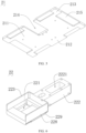
FIG. 1 is a three-dimensional schematic diagram of a pressing plate structure according to an embodiment of this application; -
FIG. 2 is a front view of a pressing plate structure according to an embodiment of this application; -
FIG. 3 is a side view of a pressing plate structure according to an embodiment of this application; -
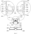
FIG. 4 is a top view of a pressing plate structure according to an embodiment of this application; -
FIG. 5 is a schematic structural diagram of a first crimping portion according to an embodiment of this application; -
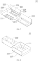
FIG. 6 is a schematic structural diagram of a second crimping portion from a first perspective according to an embodiment of this application; -
FIG. 7 is a schematic structural diagram of a second crimping portion from a second perspective according to an embodiment of this application; -
FIG. 8 is a schematic structural diagram of a second crimping portion from a third perspective according to an embodiment of this application; -
FIG. 9 is a schematic diagram showing an assembly relationship between a pressing plate structure, an electrode assembly, and an electrode assembly positioning groove according to an embodiment of this application; and -
FIG. 10 is a schematic structural diagram of a welding machine according to an embodiment of this application, with an electrode assembly positioning groove omitted. - Direction X in each accompanying drawing is a first direction in the embodiments of this application.
- Reference signs in specific embodiments are as follows:
pressing plate structure 100;frame 10;pressing block unit 20;first crimping portion 21;first sub-plate 211;transition section 212;second sub-plate 213;notch 214;process groove 215;second crimping portion 22;welding hole 221;fixing block 222;process hole 2221;crimping block 223; protrudingrib 224;first side surface 225;bottom surface 226;first shaping section 227;second side surface 228;second shaping section 229; connectingplate 23;drive mechanism 30; first limiting mechanism 31; secondlimiting mechanism 32;welding head 200;welding base 210; electrodeassembly positioning groove 300;electrode assembly 900;body 910; andtab 920. - The following describes in detail the embodiments of technical solutions of this application with reference to the accompanying drawings. The following embodiments are merely intended for a clearer description of the technical solutions of this application and therefore are used as just examples which do not constitute any limitations on the protection scope of this application.
- Unless otherwise defined, all technical and scientific terms used herein shall have the same meanings as commonly understood by persons skilled in the art to which this application belongs. The terms used herein are intended to merely describe the specific embodiments rather than to limit this application. The terms "include", "comprise", and any other variations thereof in the specification, claims and brief description of accompanying drawings of this application are intended to cover non-exclusive inclusions.
- In the description of the embodiments of this application, the terms "first", "second" and the like are merely intended to distinguish between different objects, and shall not be understood as any indication or implication of relative importance or any implicit indication of the number, particular sequence or primary-secondary relationship of the technical features indicated. In the description of this application, "a plurality of" means at least two unless otherwise specifically stated.
- In this specification, reference to "embodiment" means that specific features, structures or characteristics described with reference to the embodiment may be incorporated in at least one embodiment of this application. The word "embodiment" appearing in various places in the specification does not necessarily refer to the same embodiment or an independent or alternative embodiment that is exclusive of other embodiments. It is explicitly or implicitly understood by persons skilled in the art that the embodiments described herein may be combined with other embodiments.
- In the description of the embodiments of this application, the term "and/or" is merely for describing an associative relationship of associated objects, indicating that three relationships may be present. For example, A and/or B may indicate the following three cases: presence of only A, presence of both A and B, and presence of only B. In addition, the character "/" in this specification generally indicates an "or" relationship between contextually associated objects.
- In the description of the embodiments of this application, the term "a plurality of" means more than two (inclusive). Similarly, "a plurality of groups" means more than two (inclusive) groups, and "a plurality of pieces" means more than two (inclusive) pieces.
- In the description of the embodiments of this application, the orientations or positional relationships indicated by the technical terms "center", "longitudinal", "transverse", "length", "width", "thickness", "upper", "lower", "front", "rear", "left", "right", "perpendicular", "horizontal", "top", "bottom", "inside", "outside", "clockwise", "counterclockwise", "axial", "radial", "circumferential", and the like are based on the orientations or positional relationships as shown in the accompanying drawings. These terms are merely for the ease and brevity of description of the embodiments of this application rather than indicating or implying that the apparatuses or components mentioned must have specific orientations or must be constructed or manipulated according to specific orientations, and therefore shall not be construed as any limitations on embodiments of this application.
- In the description of the embodiments of this application, unless otherwise specified and defined explicitly, the terms "mount", "connect", "join", and "fasten" should be understood in their general senses. For example, they may refer to a fixed connection, a detachable connection, or an integral connection, may refer to a mechanical connection or electrical connection, and may refer to a direct connection, an indirect connection via an intermediate medium, or an interaction between two elements. Persons of ordinary skill in the art can understand specific meanings of these terms in this application as appropriate to specific situations.
- Currently, from a perspective of market development, application of traction batteries is becoming more and more extensive. Traction batteries have been widely used in energy storage power supply systems such as hydroelectric power plants, thermal power plants, wind power plants, and solar power plants, as well as in many other fields including electric transportation tools such as electric bicycles, electric motorcycles, and electric vehicles, and aerospace. With continuous expansion of application fields of traction batteries, market demands for the traction batteries are also expanding.
- A traction battery typically includes one or more battery cells. Each battery cell may be a secondary battery or a primary battery, and may be a lithium-sulfur battery, a sodium-ion battery, or a magnesium-ion battery, without being limited thereto.
- A battery cell typically includes one or
more electrode assemblies 900 and other functional components, where theelectrode assembly 900 is a component in which electrochemical reactions take place in the battery cell. Theelectrode assembly 900 is mainly formed by winding or stacking a positive electrode plate and a negative electrode plate, and typically a separator is provided between the positive-electrode plate and the negative-electrode plate. Parts of the positive electrode plate and negative electrode plate with active substances constitute abody 910 of theelectrode assembly 900, while parts of the positive electrode plate and negative electrode plate with no active substances each constitute atab 920. - During processing and manufacturing of the
electrode assembly 900, a part extending out of the negative electrode plate and having no active substance may be a copper foil or a copper-plated nickel foil extending in a strip shape, and a plurality of copper foil or copper-plated nickel foil layers are compacted and then welded to form a negative electrode tab. Similarly, a part extending out of the positive electrode plate and having no active substance may be an aluminum foil extending in a strip shape, and a plurality of aluminum foil layers are compacted and then welded to form a positive electrode tab. - The positive electrode tab and the negative electrode tab may both be located at one end of the
body 910 or may be located at two ends of the main body respectively. During charge and discharge of the battery, a positive electrode active substance and a negative electrode active substance react with an electrolyte, and thetab 920 can be connected to an external electrode terminal to form a current loop. - The inventors have noted that in the related art, the
electrode assembly 900 includes thebody 910 and thetab 920; due to a winding-based manufacturing method, thebody 910 is usually flat; a side portion of thebody 910 is alarge cell surface 912 with a large area; and a plurality of strip material layers capable of forming thetab 920 extend out of an end surface of thebody 910. Before a process of welding thetab 920, the plurality of strip material layers are a loose structure. During welding, generally one pressing plate is crimped onto thelarge cell surface 912, leaving a corresponding empty groove, while another pressing plate independently moves into the empty groove from outside and is crimped onto thetab 920 for welding. The two pressing plates are not positioned, and displacement deviations thereof in the vertical direction lead to loosening of crimps applied by the two pressing plates to thebody 910 and thetab 920. In addition, in the process of moving the pressing plate into the empty groove from outside and moving the pressing plate out of the empty groove after welding, unnecessary relative displacement of thetab 920 with respect to thebody 910 may occur, leading to shaking of the plurality of strip material layers and thus resulting in the occurrence of rosin joint. - To alleviate the problem of rosin joint caused by positioning deviation, the applicants have found through research that if there is no relative displacement between the two pressing plates, a distance from the
tab 920 to thebody 910 can be designed to allow the two pressing plates to respectively press thetab 920 and thebody 910 simultaneously, so that both thebody 910 and thetab 920 can be pressed during welding, thereby preventing loosening of thetab 920 and thebody 910. - Based on the above considerations, to improve the welding quality of the
tab 920, the inventors have designed a pressing plate structure through in-depth research, where a first crimpingportion 21 and a second crimpingportion 22 are fixedly connected; the second crimpingportion 22 protrudes downward from the first crimpingportion 21 in the first direction; the first crimpingportion 21 is movably disposed on theframe 10 in the first direction; when the first crimpingportion 21 moves downward to the bottommost end along the first direction, the first crimpingportion 21 abuts against thelarge cell surface 912 of thebody 910 of theelectrode assembly 900 to prevent thebody 910 from shaking during welding; and the second crimpingportion 22 can be crimped on thetab 920 of theelectrode assembly 900 to prevent thetab 920 from shaking during welding, effectively preventing the occurrence of rosin joint and improving the welding quality. - The pressing plate structure and welding machine disclosed in the embodiments of this application can be used for, but are not limited to, welding of primary batteries or secondary batteries.
- According to some embodiments of this application, referring to
FIG. 1 and further referring toFIG. 2 to FIG. 9 ,FIG. 1 is a three-dimensional schematic diagram of a pressing plate structure according to some embodiments of this application;FIG. 2 to FIG. 4 are structural schematic diagrams of a pressing plate structure from different perspectives according to some embodiments of this application;FIG. 5 is a schematic structural diagram of a first crimping portion according to some embodiments of this application;FIG. 6 to FIG. 8 are structural schematic diagrams of a second crimping portion from different perspectives according to some embodiments of this application; andFIG. 9 is a schematic diagram showing an assembly relationship between a pressing plate structure, an electrode assembly, and an electrode assembly positioning groove. - According to a first aspect, this application provides a
pressing plate structure 100 configured for welding anelectrode assembly 900. - The
electrode assembly 900 includes abody 910 and atab 920 extending out of anend surface 911 of thebody 910. It can be understood that thetab 920 is a multi-layer strip-shaped loose material before welding; and after welding, the material layers of thetab 920 are closely connected as a whole and can be connected to an external electrode terminal to form a current loop. - The
pressing plate structure 100 includes aframe 10 and apressing block unit 20. - The
pressing block unit 20 includes a first crimpingportion 21 and a second crimpingportion 22 fixedly connected to each other. - The second crimping
portion 22 protrudes downward from the first crimpingportion 21 in a first direction. In other words, the second crimpingportion 22 is located at a lower position with respect to a bottom surface of the first crimpingportion 21 facing theelectrode assembly 900, and entirely protrudes out of the bottom surface of the first crimpingportion 21. - The first crimping
portion 21 is movably disposed on theframe 10 in the first direction to approach or leave theelectrode assembly 900. The first crimpingportion 21 abuts against a side surface of thebody 910 of theelectrode assembly 900, and the second crimpingportion 22 can be crimped onto thetab 920 of theelectrode assembly 900. - Specifically, with reference to the orientations shown in
FIG. 1 and as shown inFIG. 9 , with a height difference designed between the first crimpingportion 21 and the second crimpingportion 22, when the first crimpingportion 21 moves downward to a bottommost end along the first direction, the first crimpingportion 21 abuts against alarge cell surface 912 of thebody 910 of theelectrode assembly 900 to prevent thebody 910 from shaking during welding; the second crimpingportion 22 can be crimped onto thetab 920 of theelectrode assembly 900, to prevent thetab 920 from shaking during welding; the first crimpingportion 21 and the second crimpingportion 22 are fixedly connected so that the first crimpingportion 21 and the second crimpingportion 22 are kept fixed relative to each other without a relative displacement; and thepressing block unit 20 is entirely crimped onto theelectrode assembly 900, so that pulling out and insertion of the second crimpingportion 22 are avoided during welding. In this way, the welding operation is simplified, a simplified structure is achieved, and use of a redundant operating structure in the related art is avoided. In addition, the second crimpingportion 22 can be effectively prevented from driving thetab 920 to unnecessarily loosen while being pulled out or inserted, effectively preventing the occurrence of rosin joints and improving the welding quality. - The second crimping
portion 22 is provided with awelding hole 221 extending in the first direction. When the second crimpingportion 22 is crimped onto thetab 920 of theelectrode assembly 900, part of thetab 920 is tightly pressed by a peripheral structure of thewelding hole 221, and thewelding hole 221 exposes part of thetab 920, such that a welding head 200 (mentioned hereinafter) conveniently passes through thewelding hole 221 to weld thetab 920 exposed in thewelding hole 221, thereby ensuring that thetab 920 is welded at a same site every time, improving the consistency of welding. - In some embodiments, the first crimping
portion 21 and the second crimpingportion 22 can be integrally processed and formed, with high structural strength and a high-precision height difference therebetween. Certainly, in some other embodiments, the first crimpingportion 21 and the second crimpingportion 22 can be separately processed and then connected using bolts or directly welded, with a simple process and a low cost. - In some embodiments, as shown in
FIG. 7 , the second crimpingportion 22 is provided with twowelding holes 221, and the twowelding holes 221 are arranged side by side. Typically, thebody 910 of oneelectrode assembly 900 includes two groups oftabs 920, where one group oftabs 920 are positive electrode tabs, and the other group oftabs 920 are negative electrode tabs. One battery cell may include twoelectrode assemblies 900; the positive electrode tabs of the twoelectrode assemblies 900 are connected using an adapting piece (not marked); the negative electrode tabs of the twoelectrode assemblies 900 are connected using another adapting piece; and twowelding holes 221 are arranged side by side so as to expose the positive electrode tabs of both the twoelectrode assemblies 900 or expose the negative electrode tabs of both the twoelectrode assemblies 900, so that thetabs 920 of the twoelectrode assemblies 900 can be welded in one welding process, improving the welding efficiency. Certainly, in some other embodiments, the second crimpingportion 22 may be provided with one, three, or more welding holes 221. This is not limited in the embodiments of this application. - In some embodiments, as shown in
FIG. 7 , a cross section of thewelding hole 221 is rectangular. In some other embodiments, the cross section of thewelding hole 221 may be circular, elliptic, triangular, or the like. - It can be understood that in the embodiments of this application, with reference to the orientations shown in
FIG. 1 , direction X is the first direction, which is typically the vertical direction. In some other embodiments, the first direction may be another direction. This is not limited in this application. - In some embodiments, as shown in
FIG. 1 to FIG. 5 ,FIG. 9 , andFIG. 10 , the first crimpingportion 21 includes afirst sub-plate 211, atransition section 212, and asecond sub-plate 213. - The
first sub-plate 211 and the second sub-plate 213 can be integrally connected via thetransition section 212. Thefirst sub-plate 211 and thesecond sub-plate 213 are typically the same in length, width, thickness and shape and are symmetrically designed. However, in some other embodiments, thefirst sub-plate 211 and thesecond sub-plate 213 may also be different in length, width, thickness and shape. This is not limited in the embodiments of this application. - The
first sub-plate 211 and thesecond sub-plate 213 are respectively connected to a left side and a right side of thetransition section 212, thetransition section 212 is shorter than thefirst sub-plate 211, and thetransition section 212 is shorter than thesecond sub-plate 213. In this way, anotch 214 can be formed between thefirst sub-plate 211 and thesecond sub-plate 213. Thenotch 214 is typically in a U shape, or may be designed in a semicircular shape or other shapes as required. - At least part of the second crimping
portion 22 is disposed in thenotch 214. - Specifically, when the first crimping
portion 21 abuts against theelectrode assembly 900, thefirst sub-plate 211 and thesecond sub-plate 213 are crimped onto thelarge cell surfaces 912 of thebodies 910 of twoelectrode assemblies 900, respectively, so as to prevent thebodies 910 from shaking during welding. A position facing thenotch 214 is just over thetabs 920 of the twoelectrode assemblies 900. In this way, the second crimpingportion 22 can be crimped onto thetabs 920 of both the twoelectrode assemblies 900, and thewelding head 200 can pass through thenotch 214 and thewelding hole 221 in sequence to weld thetab 920. - In some embodiments, the first crimping
portion 21 is typically an aluminum plate, a carbon steel plate, or a stainless steel plate. As shown inFIG. 5 , aprocess groove 215 is formed on the bottom surface of the first crimpingportion 21 and is configured to fit with other structures, thereby preventing interference and reducing weight. - In some embodiments, as shown in
FIG. 1 to FIG. 4 andFIG. 6 to FIG. 9 , the second crimpingportion 22 includes a fixingblock 222 and a crimpingblock 223. - The fixing
block 222 is detachably connected to thetransition section 212. - Bottom surfaces of the
first sub-plate 211,second sub-plate 213 andtransition section 212 are typically at a same horizontal level, and the fixingblock 222 is fixed to the bottom surface of thetransition section 212 facing theelectrode assembly 900. In this way, with the bottom of thetransition section 212 as an original point, the fixingblock 222 can protrude downward a specified distance in the first direction, and that distance can be determined by designing thickness of the fixingblock 222, achieving good manufacturability. The fixingblock 222 and thetransition section 212 are connected using a bolt, facilitating disassembly and maintenance. - When the first crimping
portion 21 abuts against theelectrode assembly 900, thefirst sub-plate 211 and thesecond sub-plate 213 are crimped onto thelarge cell surfaces 912 of thebodies 910 of twoelectrode assemblies 900, respectively; a position facing thenotch 214 is just over thetabs 920 of the twoelectrode assemblies 900; the fixingblock 222 is detachably connected to thetransition section 212; the crimpingblock 223 is located in thenotch 214; thewelding hole 221 runs through the crimpingblock 223 in the first direction; and there may be two weldingholes 221 on the crimpingblock 223 to correspond to the twoelectrode assemblies 900. In this way, the crimpingblock 223 can be crimped onto thetabs 920 of the twoelectrode assemblies 900, and thewelding head 200 can pass through thenotch 214 and thewelding hole 221 in sequence to weld thetab 920. - In some possible embodiments, the fixing
block 222 and the crimpingblock 223 are integrally connected and may be integrally processed using stainless steel or aluminum, with good connection strength and a small size deviation therebetween. In some other embodiments, the fixingblock 222 and the crimpingblock 223 are separately processed and then fixedly connected by welding or using bolts. - In some embodiments, as shown in
FIG. 6 , the fixingblock 222 is provided with a plurality of process holes 2221. Without affecting the structural strength, weight of the second crimpingportion 22 is reduced as far as possible, thereby reducing weight of the overall welding machine. - In some embodiments, as shown in
FIG. 7 andFIG. 9 , thebottom surface 226 of the crimpingblock 223 facing thetab 920 is provided with aprotruding rib 224. - When the first crimping
portion 21 abuts against theelectrode assembly 900, thefirst sub-plate 211 and thesecond sub-plate 213 are crimped onto thelarge cell surfaces 912 of thebodies 910 of twoelectrode assemblies 900, respectively; a position facing thenotch 214 is just over thetabs 920 of the twoelectrode assemblies 900; the crimpingblock 223 is located in thenotch 214; the crimpingblock 223 is crimped onto thetab 920 of theelectrode assembly 900; with the protrudingrib 224 formed on thebottom surface 226 of the crimpingblock 223 facing thetab 920, a contact area between the crimpingblock 223 and thetab 920 can be effectively reduced, so that intensity of pressure per unit area under the same crimping force is enhanced, making the crimpingblock 223 be crimped onto thetab 920 more stably and preventing the crimpingblock 223 from loosening; thewelding hole 221 runs through the crimpingblock 223 in the first direction; and thewelding head 200 can pass through thenotch 214 and thewelding hole 221 in sequence to weld thetab 920, preventing the occurrence of rosin joint and improving the welding quality. - In some embodiments, as shown in
FIG. 7 , the protrudingrib 224 is disposed around thewelding hole 221, so that a peripheral region of thewelding hole 221 is crimped onto thetab 920 more stably, thereby avoiding loosening. - In some other embodiments, a plurality of protruding
ribs 224 may be arranged linearly. This is not limited in the embodiments of this application. - In some embodiments, as shown in
FIG. 2 andFIG. 9 , afirst shaping section 227 is formed at a junction between afirst side surface 225 of the crimpingblock 223 close to thefirst sub-plate 211 and thebottom surface 226 of the crimpingblock 223 facing thetab 920. Asecond shaping section 229 is formed at a junction between asecond side surface 228 of the crimpingblock 223 close to thesecond sub-plate 213 and thebottom surface 226 of the crimpingblock 223 facing thetab 920. - The
first shaping section 227 and thesecond shaping section 229 may be inclined surfaces or smooth arc surfaces. - When the first crimping
portion 21 abuts against theelectrode assembly 900, thefirst sub-plate 211 and thesecond sub-plate 213 are crimped onto thelarge cell surfaces 912 of thebodies 910 of twoelectrode assemblies 900, respectively; the crimpingblock 223 is crimped onto thetabs 920 of the twoelectrode assemblies 900; and thefirst shaping section 227 and thesecond shaping section 229 move downward along the first direction until abutting against root regions of thetabs 920 and thebodies 910. It should be understood that thetab 920 is a loose multi-layer structure before welding, relatively many gaps are present in a root portion of thetab 920, and the root portion is difficult to compact by thebottom surface 226 of the crimpingblock 223, so that voids are prone to occur. However, if thefirst side surface 225 and thebottom surface 226 form a sharp right-angled structure therebetween, and thesecond side surface 228 and thebottom surface 226 form a sharp right-angled structure therebetween, the two right-angled structures directly squeeze thetab 920 of a multi-layer structure, resulting in cracking of an outermost layer of thetab 920. With provision of thefirst shaping section 227 and thesecond shaping section 229, a smooth arc surface or a transition inclined surface is formed, thus a shaping function is provided, which not only avoids formation of the voids in thetab 920, but also prevents cracking of thetab 920 during welding, effectively improving the welding quality. - In some embodiments, as shown in
FIG. 1 to FIG. 4 andFIG. 10 , the pressing plate structure includes adrive mechanism 30. - The
drive mechanism 30 is fixed to theframe 10, and thedrive mechanism 30 is in transmission connection with the first crimpingportion 21 so as to drive the first crimpingportion 21 to movably approach or leave theelectrode assembly 900 along the first direction. - The
drive mechanism 30 is a cylinder or a motor. - In an example in which the
drive mechanism 30 is a cylinder, an acting shaft (not marked) of thedrive mechanism 30 may be provided with a first limiting mechanism 31 and a second limitingmechanism 32 in the first direction. As shown inFIG. 2 , the first limiting mechanism 31 and the second limitingmechanism 32 may be two baffle plates arranged in the first direction for limiting an action length of thedrive mechanism 30. - Specifically, the
drive mechanism 30 drives the first crimpingportion 21 to move downward along the first direction until the acting shaft of thedrive mechanism 30 is limited by the first limiting mechanism 31. At that point, the first crimpingportion 21 abuts against theelectrode assembly 900, thefirst sub-plate 211 and thesecond sub-plate 213 are crimped onto thelarge cell surfaces 912 of thebodies 910 of the twoelectrode assemblies 900, respectively, the crimpingblock 223 is crimped onto thetabs 920 of the twoelectrode assemblies 900, and thewelding head 200 can pass through thenotch 214 and thewelding hole 221 in sequence to weld thetabs 920. The downward movement along the first direction herein means that the first crimpingportion 21 approaches theelectrode assembly 900. - After welding, the
drive mechanism 30 drives the first crimpingportion 21 to move upward along the first direction until the acting shaft of thedrive mechanism 30 is limited by the second limitingmechanism 32. At that point, thefirst sub-plate 211 and the second sub-plate 213 both leave thelarge cell surfaces 912 of thebodies 910 of the twoelectrode assemblies 920, and the crimpingblock 223 also leaves thetabs 900 of the twoelectrode assemblies 900, such that the weldedelectrode assemblies 900 are conveniently moved away for a subsequent procedure, thereby leaving space for placing anotherelectrode assembly 900 to be welded. - In some embodiments, the first limiting mechanism 31 and the second limiting
mechanism 32 may be magnetic inductors. Air regulation valves (not marked) may be connected in series in an air inlet chamber of thedrive mechanism 30. When the first limiting mechanism 31 and the second limitingmechanism 32 sense that thedrive mechanism 30 has moved to a corresponding position, a command is sent to the air regulation valves to enable or disable air input by thedrive mechanism 30, such that thedrive mechanism 30 drives the first crimpingportion 21 to movably approach or leave theelectrode assembly 900 along the first direction. - In some embodiments, as shown in
FIG. 1 to FIG. 4 , thepressing block unit 20 includes a connectingplate 23, where the connectingplate 23 is connected to thedrive mechanism 30, and the connectingplate 23 is connected to a surface of the first crimpingportion 21 facing away from theelectrode assembly 900. - The acting shaft of the
drive mechanism 30 is connected to a middle portion of the connectingplate 23; the middle portion of the connectingplate 23 is fixed to thetransition section 212; and two sides of the connectingplate 23 extend to thefirst sub-plate 211 and thesecond sub-plate 213 respectively, thereby ensuring that no deflection occurs when thedrive mechanism 30 is driving the first crimpingportion 21, and ensuring a crimping effect of thepressing block unit 20 on theelectrode assembly 900. Thus, situations such as the occurrence of rosin joint is avoided, and the welding quality is improved. - The connecting
plate 23 and thefirst sub-plate 211, as well as the connectingplate 23 and the second sub-plate 213 can be connected using a bolt or by welding. - According to a second aspect, this application provides a welding machine including the foregoing
pressing plate structure 100. - In some embodiments, as shown in
FIG. 9 andFIG. 10 , the welding machine of this application is an ultrasonic welding machine. The welding machine may typically include structures such as awelding head 200, awelding base 210, and an electrodeassembly positioning groove 300. Theelectrode assembly 900 is arranged in the electrodeassembly positioning groove 300. Thedrive mechanism 30 drives the first crimpingportion 21 and the second crimpingportion 22 to be crimped onto thebody 910 and thetab 920 of theelectrode assembly 900, respectively. Thewelding head 200 and thewelding base 210 respectively implement ultrasonic welding on thetab 920 in the vertical direction. - In conclusion, it should be noted that the technical features in the foregoing embodiments may be combined in any way. For brevity of description, not all the possible combinations of the technical features in the foregoing embodiments are described. However, as long as there is no contradiction among the combinations of these technical features, all these combinations shall be construed as being within the scope recorded in this specification.
- The foregoing embodiments show merely several implementations of this application, and descriptions thereof are specific and detailed, but should not be construed as any limitation on the scope of this patent. It should be noted that those of ordinary skill in the art may further make several modifications and improvements without departing from the concept of this application, and these modifications and improvements also fall within the protection scope of this application. Therefore, the protection scope of this application should be subject to the appended claims.
Claims (11)
- A pressing plate structure, comprising:a frame (10); anda pressing block unit (20), wherein the pressing block unit (20) comprises a first crimping portion (21) and a second crimping portion (22) fixedly connected to each other; the first crimping portion (21) is movably disposed on the frame (10) in a first direction to approach or leave an electrode assembly (900); the second crimping portion (22) protrudes downward from the first crimping portion (21) in the first direction; and the second crimping portion (22) is provided with a welding hole (221) extending in the first direction; andthe second crimping portion (22) is capable of being crimped onto a tab (920) of the electrode assembly (900), and the welding hole (221) exposes part of the tab (920).
- The pressing plate structure according to claim 1, wherein the first crimping portion (21) comprises a first sub-plate (211), a transition section (212), and a second sub-plate (213);the first sub-plate (211) and the second sub-plate (213) are respectively connected to a left side and a right side of the transition section (212), and the transition section (212) is shorter than the first sub-plate (211), so as to form a notch (214); andat least part of the second crimping portion (22) is disposed in the notch (214).
- The pressing plate structure according to claim 2, wherein the second crimping portion (22) comprises a fixing block (222) and a crimping block (223); the fixing block (222) is detachably connected to the transition section (212); the crimping block (223) is located in the notch (214); and the welding hole (221) runs through the crimping block (223) in the first direction.
- The pressing plate structure according to claim 3, wherein a bottom surface of the crimping block (223) facing the tab (920) is provided with a protruding rib (224).
- The pressing plate structure according to claim 4, wherein the protruding rib (224) is arranged around the welding hole (221).
- The pressing plate structure according to any one of claims 3 to 5, wherein a first shaping section (227) is formed at a junction between a first side surface of the crimping block (223) close to the first sub-plate (211) and the bottom surface of the crimping block (223) facing the tab (920); and/or
a second shaping section (229) is formed at a junction between a second side surface of the crimping block (223) close to the second sub-plate (213) and the bottom surface of the crimping block (223) facing the tab (920). - The pressing plate structure according to any one of claims 1 to 6, wherein the pressing plate structure comprises a drive mechanism (30); and
the drive mechanism (30) is fixed to the frame (10); and the drive mechanism (30) is in transmission connection with the first crimping portion (21) so as to drive the first crimping portion (21) to movably approach or leave the electrode assembly (900) along the first direction. - The pressing plate structure according to claim 7, wherein the pressing block unit (20) comprises a connecting plate (23); the connecting plate (23) is connected to the drive mechanism (30); and the connecting plate (23) is connected to a surface of the first crimping portion (21) facing away from the electrode assembly (900).
- The pressing plate structure according to any one of claims 1 to 8, wherein the first crimping portion (21) and the second crimping portion (22) are integrally connected.
- A welding machine, comprising the pressing plate structure (100) according to any one of claims 1 to 9.
- The welding machine according to claim 10, wherein the welding machine is an ultrasonic welding machine.
Applications Claiming Priority (2)
| Application Number | Priority Date | Filing Date | Title |
|---|---|---|---|
| CN202223050340.4U CN218695333U (en) | 2022-11-16 | 2022-11-16 | Pressing plate structure and welding machine |
| PCT/CN2023/084728 WO2024103595A1 (en) | 2022-11-16 | 2023-03-29 | Pressing plate structure and welding machine |
Publications (3)
| Publication Number | Publication Date |
|---|---|
| EP4393622A1 true EP4393622A1 (en) | 2024-07-03 |
| EP4393622A4 EP4393622A4 (en) | 2025-04-09 |
| EP4393622B1 EP4393622B1 (en) | 2026-03-04 |
Family
ID=85619273
Family Applications (1)
| Application Number | Title | Priority Date | Filing Date |
|---|---|---|---|
| EP23731080.0A Active EP4393622B1 (en) | 2022-11-16 | 2023-03-29 | Pressing plate structure and welding machine with such pressing structure |
Country Status (5)
| Country | Link |
|---|---|
| US (1) | US20240157488A1 (en) |
| EP (1) | EP4393622B1 (en) |
| CN (1) | CN218695333U (en) |
| ES (1) | ES3068974T3 (en) |
| WO (1) | WO2024103595A1 (en) |
Families Citing this family (3)
| Publication number | Priority date | Publication date | Assignee | Title |
|---|---|---|---|---|
| CN218695333U (en) * | 2022-11-16 | 2023-03-24 | 宁德时代新能源科技股份有限公司 | Pressing plate structure and welding machine |
| CN117644352B (en) * | 2024-01-30 | 2024-05-28 | 宁德时代新能源科技股份有限公司 | Welding positioning device, battery production line and welding method |
| CN121267356A (en) * | 2024-07-02 | 2026-01-06 | 北京车和家汽车科技有限公司 | Briquetting tool and welding method of pole and pole lug |
Family Cites Families (13)
| Publication number | Priority date | Publication date | Assignee | Title |
|---|---|---|---|---|
| JPS595394B2 (en) * | 1980-07-10 | 1984-02-04 | 住友精密工業株式会社 | Automatic fillet weld copying device |
| JPS60255271A (en) * | 1984-05-31 | 1985-12-16 | Nippon Kokan Kk <Nkk> | Multilayer welding control method |
| CN102306826B (en) * | 2011-08-17 | 2012-11-21 | 苏州金科发锂电池有限公司 | Impact resistant and vibration resistant lithium/thionyl chloride battery |
| KR101269945B1 (en) * | 2011-11-18 | 2013-05-31 | 세방전지(주) | Automatic welding aparatus for battery |
| JP6084887B2 (en) * | 2013-04-16 | 2017-02-22 | 川崎重工業株式会社 | Friction stir welding apparatus and friction stir welding method |
| DE102015209719B4 (en) * | 2015-05-27 | 2019-06-19 | Thyssenkrupp Ag | Hold-down device, welding device and method for ultrasonic welding |
| KR102055634B1 (en) * | 2018-05-08 | 2019-12-13 | 최보름 | Apparatus for Welding of Storage Battery |
| CN212011114U (en) * | 2020-04-26 | 2020-11-24 | 宁德时代新能源科技股份有限公司 | Secondary battery, battery module, and device using secondary battery as power source |
| CN214350239U (en) * | 2020-11-05 | 2021-10-08 | 银隆新能源股份有限公司 | Positioning device and welding equipment |
| CN216958259U (en) * | 2022-01-11 | 2022-07-12 | 江苏正力新能电池技术有限公司 | Battery top cover insulating part and power battery |
| CN217507593U (en) * | 2022-04-29 | 2022-09-27 | 瑞浦兰钧能源股份有限公司 | A bare cell structure and fixture |
| CN115041802B (en) * | 2022-05-26 | 2024-09-06 | 中航锂电(洛阳)有限公司 | Press-holding module, pressing device and welding equipment |
| CN218695333U (en) * | 2022-11-16 | 2023-03-24 | 宁德时代新能源科技股份有限公司 | Pressing plate structure and welding machine |
-
2022
- 2022-11-16 CN CN202223050340.4U patent/CN218695333U/en active Active
-
2023
- 2023-03-29 WO PCT/CN2023/084728 patent/WO2024103595A1/en not_active Ceased
- 2023-03-29 EP EP23731080.0A patent/EP4393622B1/en active Active
- 2023-03-29 ES ES23731080T patent/ES3068974T3/en active Active
- 2023-07-10 US US18/349,721 patent/US20240157488A1/en active Pending
Also Published As
| Publication number | Publication date |
|---|---|
| EP4393622A4 (en) | 2025-04-09 |
| CN218695333U (en) | 2023-03-24 |
| US20240157488A1 (en) | 2024-05-16 |
| ES3068974T3 (en) | 2026-06-03 |
| WO2024103595A1 (en) | 2024-05-23 |
| EP4393622B1 (en) | 2026-03-04 |
Similar Documents
| Publication | Publication Date | Title |
|---|---|---|
| EP4393622B1 (en) | Pressing plate structure and welding machine with such pressing structure | |
| KR101161965B1 (en) | Current collector terminal plate for secondary battery, secondary battery, and method for producing secondary battery | |
| KR20230093033A (en) | Battery cells, batteries and electrical devices | |
| US20210249743A1 (en) | Battery and battery manufacturing method | |
| CN211045490U (en) | Secondary battery, and top cover assembly, battery module and device used for secondary battery | |
| US20250105305A1 (en) | Electrode assembly, battery cell, battery, and electric apparatus | |
| DE112013004522T5 (en) | Battery, battery pack and method of manufacturing a battery | |
| WO2024082639A1 (en) | Tab coating device | |
| US20240170809A1 (en) | Tab welding method, welding tool, battery cell, battery, and electric device | |
| CN118589159A (en) | Battery cell, battery, electric device, welding device and welding method | |
| CN111211285B (en) | High-capacity lithium battery with high-energy density multi-pole structure | |
| WO2025044211A1 (en) | Battery cell, manufacturing method therefor, battery, and electrical apparatus | |
| WO2025208801A9 (en) | Battery and electric device | |
| WO2025102631A1 (en) | Battery cell, manufacturing method therefor, battery, and electrical apparatus | |
| JP2001126708A (en) | Manufacturing method of non-aqueous electrolyte battery | |
| CN223414241U (en) | Cylindrical batteries and electrical equipment | |
| CN220856847U (en) | Assembly component of battery core and current collector and battery | |
| US20240266616A1 (en) | Electrode plate and manufacturing method thereof, electrode assembly and manufacturing method thereof, battery cell, and battery | |
| CN119208763A (en) | A high-performance fast temperature-control all-solid-state square battery and its preparation method | |
| EP4579924A1 (en) | Battery cell, battery and electric device | |
| CN217823184U (en) | High-capacity battery | |
| CN223514188U (en) | Secondary battery | |
| KR20220033437A (en) | Battery and battery case included in battery, and battery case member for building battery case | |
| EP4579895A1 (en) | Cylindrical battery | |
| CN221538609U (en) | Welding device, battery cell, battery and electricity utilization device |
Legal Events
| Date | Code | Title | Description |
|---|---|---|---|
| STAA | Information on the status of an ep patent application or granted ep patent |
Free format text: STATUS: UNKNOWN |
|
| STAA | Information on the status of an ep patent application or granted ep patent |
Free format text: STATUS: THE INTERNATIONAL PUBLICATION HAS BEEN MADE |
|
| PUAI | Public reference made under article 153(3) epc to a published international application that has entered the european phase |
Free format text: ORIGINAL CODE: 0009012 |
|
| STAA | Information on the status of an ep patent application or granted ep patent |
Free format text: STATUS: REQUEST FOR EXAMINATION WAS MADE |
|
| 17P | Request for examination filed |
Effective date: 20230623 |
|
| AK | Designated contracting states |
Kind code of ref document: A1 Designated state(s): AL AT BE BG CH CY CZ DE DK EE ES FI FR GB GR HR HU IE IS IT LI LT LU LV MC ME MK MT NL NO PL PT RO RS SE SI SK SM TR |
|
| RAP1 | Party data changed (applicant data changed or rights of an application transferred) |
Owner name: CONTEMPORARY AMPEREX TECHNOLOGY(HONG KONG) LIMITED |
|
| REG | Reference to a national code |
Ref country code: DE Ref legal event code: R079 Free format text: PREVIOUS MAIN CLASS: B23B0037000000 Ipc: B23K0037040000 Ref country code: DE Ref legal event code: R079 Ref document number: 602023013066 Country of ref document: DE Free format text: PREVIOUS MAIN CLASS: B23B0037000000 Ipc: B23K0037040000 |
|
| A4 | Supplementary search report drawn up and despatched |
Effective date: 20250307 |
|
| RIC1 | Information provided on ipc code assigned before grant |
Ipc: B23K 101/38 20060101ALN20250303BHEP Ipc: B23K 20/10 20060101ALI20250303BHEP Ipc: B23K 37/04 20060101AFI20250303BHEP |
|
| GRAP | Despatch of communication of intention to grant a patent |
Free format text: ORIGINAL CODE: EPIDOSNIGR1 |
|
| STAA | Information on the status of an ep patent application or granted ep patent |
Free format text: STATUS: GRANT OF PATENT IS INTENDED |
|
| RIC1 | Information provided on ipc code assigned before grant |
Ipc: B23K 37/04 20060101AFI20251007BHEP Ipc: B23K 20/10 20060101ALI20251007BHEP Ipc: B23K 101/38 20060101ALN20251007BHEP |
|
| RIC1 | Information provided on ipc code assigned before grant |
Ipc: B23K 37/04 20060101AFI20251015BHEP Ipc: B23K 20/10 20060101ALI20251015BHEP Ipc: B23K 101/38 20060101ALN20251015BHEP |
|
| DAV | Request for validation of the european patent (deleted) | ||
| DAX | Request for extension of the european patent (deleted) | ||
| INTG | Intention to grant announced |
Effective date: 20251031 |
|
| GRAS | Grant fee paid |
Free format text: ORIGINAL CODE: EPIDOSNIGR3 |
|
| GRAA | (expected) grant |
Free format text: ORIGINAL CODE: 0009210 |
|
| STAA | Information on the status of an ep patent application or granted ep patent |
Free format text: STATUS: THE PATENT HAS BEEN GRANTED |
|
| AK | Designated contracting states |
Kind code of ref document: B1 Designated state(s): AL AT BE BG CH CY CZ DE DK EE ES FI FR GB GR HR HU IE IS IT LI LT LU LV MC ME MK MT NL NO PL PT RO RS SE SI SK SM TR |
|
| REG | Reference to a national code |
Ref country code: CH Ref legal event code: F10 Free format text: ST27 STATUS EVENT CODE: U-0-0-F10-F00 (AS PROVIDED BY THE NATIONAL OFFICE) Effective date: 20260304 Ref country code: GB Ref legal event code: FG4D |
|
| REG | Reference to a national code |
Ref country code: IE Ref legal event code: FG4D |
|
| REG | Reference to a national code |
Ref country code: DE Ref legal event code: R096 Ref document number: 602023013066 Country of ref document: DE |
|
| PGFP | Annual fee paid to national office [announced via postgrant information from national office to epo] |
Ref country code: DE Payment date: 20260324 Year of fee payment: 4 |
|
| PGFP | Annual fee paid to national office [announced via postgrant information from national office to epo] |
Ref country code: AT Payment date: 20260303 Year of fee payment: 4 |
|
| PGFP | Annual fee paid to national office [announced via postgrant information from national office to epo] |
Ref country code: FR Payment date: 20260330 Year of fee payment: 4 |
|
| REG | Reference to a national code |
Ref country code: ES Ref legal event code: FG2A Ref document number: 3068974 Country of ref document: ES Kind code of ref document: T3 Effective date: 20260603 |
|
| PG25 | Lapsed in a contracting state [announced via postgrant information from national office to epo] |
Ref country code: RS Free format text: LAPSE BECAUSE OF FAILURE TO SUBMIT A TRANSLATION OF THE DESCRIPTION OR TO PAY THE FEE WITHIN THE PRESCRIBED TIME-LIMIT Effective date: 20260604 |
|
| PGFP | Annual fee paid to national office [announced via postgrant information from national office to epo] |
Ref country code: ES Payment date: 20260401 Year of fee payment: 4 |
|
| REG | Reference to a national code |
Ref country code: NL Ref legal event code: MP Effective date: 20260304 |
|
| PG25 | Lapsed in a contracting state [announced via postgrant information from national office to epo] |
Ref country code: PL Free format text: LAPSE BECAUSE OF FAILURE TO SUBMIT A TRANSLATION OF THE DESCRIPTION OR TO PAY THE FEE WITHIN THE PRESCRIBED TIME-LIMIT Effective date: 20260304 |
|
| PG25 | Lapsed in a contracting state [announced via postgrant information from national office to epo] |
Ref country code: GR Free format text: LAPSE BECAUSE OF FAILURE TO SUBMIT A TRANSLATION OF THE DESCRIPTION OR TO PAY THE FEE WITHIN THE PRESCRIBED TIME-LIMIT Effective date: 20260605 |
|
| REG | Reference to a national code |
Ref country code: LT Ref legal event code: MG9D |
|
| PG25 | Lapsed in a contracting state [announced via postgrant information from national office to epo] |
Ref country code: LT Free format text: LAPSE BECAUSE OF FAILURE TO SUBMIT A TRANSLATION OF THE DESCRIPTION OR TO PAY THE FEE WITHIN THE PRESCRIBED TIME-LIMIT Effective date: 20260304 |
|
| PG25 | Lapsed in a contracting state [announced via postgrant information from national office to epo] |
Ref country code: NO Free format text: LAPSE BECAUSE OF FAILURE TO SUBMIT A TRANSLATION OF THE DESCRIPTION OR TO PAY THE FEE WITHIN THE PRESCRIBED TIME-LIMIT Effective date: 20260604 |
|
| PG25 | Lapsed in a contracting state [announced via postgrant information from national office to epo] |
Ref country code: FI Free format text: LAPSE BECAUSE OF FAILURE TO SUBMIT A TRANSLATION OF THE DESCRIPTION OR TO PAY THE FEE WITHIN THE PRESCRIBED TIME-LIMIT Effective date: 20260304 Ref country code: SE Free format text: LAPSE BECAUSE OF FAILURE TO SUBMIT A TRANSLATION OF THE DESCRIPTION OR TO PAY THE FEE WITHIN THE PRESCRIBED TIME-LIMIT Effective date: 20260304 |
|
| PG25 | Lapsed in a contracting state [announced via postgrant information from national office to epo] |
Ref country code: HR Free format text: LAPSE BECAUSE OF FAILURE TO SUBMIT A TRANSLATION OF THE DESCRIPTION OR TO PAY THE FEE WITHIN THE PRESCRIBED TIME-LIMIT Effective date: 20260304 |
|
| PG25 | Lapsed in a contracting state [announced via postgrant information from national office to epo] |
Ref country code: LV Free format text: LAPSE BECAUSE OF FAILURE TO SUBMIT A TRANSLATION OF THE DESCRIPTION OR TO PAY THE FEE WITHIN THE PRESCRIBED TIME-LIMIT Effective date: 20260304 |
|
| PG25 | Lapsed in a contracting state [announced via postgrant information from national office to epo] |
Ref country code: BG Free format text: LAPSE BECAUSE OF FAILURE TO SUBMIT A TRANSLATION OF THE DESCRIPTION OR TO PAY THE FEE WITHIN THE PRESCRIBED TIME-LIMIT Effective date: 20260304 |
|
| P01 | Opt-out of the competence of the unified patent court (upc) registered |
Free format text: CASE NUMBER: UPC_APP_0020758_4393622/2026 Effective date: 20260706 |