EP4393384A1 - Blutdruckmessvorrichtung und elektronische vorrichtung - Google Patents
Blutdruckmessvorrichtung und elektronische vorrichtung Download PDFInfo
- Publication number
- EP4393384A1 EP4393384A1 EP22910101.9A EP22910101A EP4393384A1 EP 4393384 A1 EP4393384 A1 EP 4393384A1 EP 22910101 A EP22910101 A EP 22910101A EP 4393384 A1 EP4393384 A1 EP 4393384A1
- Authority
- EP
- European Patent Office
- Prior art keywords
- air
- cavity
- value
- airbag
- air pressure
- Prior art date
- Legal status (The legal status is an assumption and is not a legal conclusion. Google has not performed a legal analysis and makes no representation as to the accuracy of the status listed.)
- Pending
Links
Images


Classifications
-
- A—HUMAN NECESSITIES
- A61—MEDICAL OR VETERINARY SCIENCE; HYGIENE
- A61B—DIAGNOSIS; SURGERY; IDENTIFICATION
- A61B5/00—Measuring for diagnostic purposes; Identification of persons
- A61B5/02—Detecting, measuring or recording for evaluating the cardiovascular system, e.g. pulse, heart rate, blood pressure or blood flow
- A61B5/021—Measuring pressure in heart or blood vessels
- A61B5/02141—Details of apparatus construction, e.g. pump units or housings therefor, cuff pressurising systems, arrangements of fluid conduits or circuits
-
- A—HUMAN NECESSITIES
- A61—MEDICAL OR VETERINARY SCIENCE; HYGIENE
- A61B—DIAGNOSIS; SURGERY; IDENTIFICATION
- A61B5/00—Measuring for diagnostic purposes; Identification of persons
- A61B5/02—Detecting, measuring or recording for evaluating the cardiovascular system, e.g. pulse, heart rate, blood pressure or blood flow
- A61B5/021—Measuring pressure in heart or blood vessels
- A61B5/022—Measuring pressure in heart or blood vessels by applying pressure to close blood vessels, e.g. against the skin; Ophthalmodynamometers
- A61B5/02225—Measuring pressure in heart or blood vessels by applying pressure to close blood vessels, e.g. against the skin; Ophthalmodynamometers using the oscillometric method
-
- A—HUMAN NECESSITIES
- A61—MEDICAL OR VETERINARY SCIENCE; HYGIENE
- A61B—DIAGNOSIS; SURGERY; IDENTIFICATION
- A61B5/00—Measuring for diagnostic purposes; Identification of persons
- A61B5/02—Detecting, measuring or recording for evaluating the cardiovascular system, e.g. pulse, heart rate, blood pressure or blood flow
- A61B5/021—Measuring pressure in heart or blood vessels
- A61B5/022—Measuring pressure in heart or blood vessels by applying pressure to close blood vessels, e.g. against the skin; Ophthalmodynamometers
- A61B5/0225—Measuring pressure in heart or blood vessels by applying pressure to close blood vessels, e.g. against the skin; Ophthalmodynamometers the pressure being controlled by electric signals, e.g. derived from Korotkoff sounds
-
- A—HUMAN NECESSITIES
- A61—MEDICAL OR VETERINARY SCIENCE; HYGIENE
- A61B—DIAGNOSIS; SURGERY; IDENTIFICATION
- A61B5/00—Measuring for diagnostic purposes; Identification of persons
- A61B5/68—Arrangements of detecting, measuring or recording means, e.g. sensors, in relation to patient
- A61B5/6801—Arrangements of detecting, measuring or recording means, e.g. sensors, in relation to patient specially adapted to be attached to or worn on the body surface
- A61B5/6802—Sensor mounted on worn items
- A61B5/681—Wristwatch-type devices
Definitions
- This application relates to the field of electronic device technologies, and in particular, to a blood pressure measurement device and an electronic device.
- a micro pump and a pressure sensor are directly placed inside a body of the blood pressure measurement device.
- the pressure sensor may obtain a blood pressure value of a user by measuring air pressure of the blood pressure measurement device.
- the micro pump inflates an airbag with air inside the body, an air flow is generated in an inflating process, and the air flow causes fluctuation of air pressure. Consequently, air pressure detected by the pressure sensor is unstable, and accuracy of a blood pressure value measured by the blood pressure measurement device is affected.
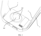
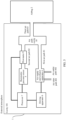
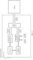
- the blood pressure measurement device may include a body, a processor, an airbag, an air supply and exhaust apparatus, a driving apparatus, a barometric pressure sensor, and a flowmeter.
- the body includes a cavity, and function modules or components of the blood pressure measurement device may be disposed in the cavity.
- the foregoing driving apparatus, the processor, the air supply and exhaust apparatus, and the barometric pressure sensor may be disposed in the cavity.
- the airbag is fastened to an end of the body, and the airbag has an air cavity.
- the air supply and exhaust apparatus includes an air inlet path and an air outlet path, and the air supply and exhaust apparatus is connected to the air cavity of the airbag through a first air path.
- the barometric pressure sensor may be connected to the air cavity of the airbag through a second air path, to detect an air pressure value in the air cavity.
- the flowmeter is configured to detect an air flow value of air flowing between the air supply and exhaust apparatus and the airbag, or is configured to detect an air flow value of air flowing between the barometric pressure sensor and the airbag.
- the blood pressure measurement device stores a correspondence between an air flow value and an air pressure compensation value, for example, stores the correspondence in the processor.
- the processor is electrically connected to the barometric pressure sensor, the flowmeter, and the driving apparatus.
- the processor may obtain an air pressure compensation value based on the air flow value detected by the flowmeter and the stored correspondence between an air flow value and an air pressure compensation value, to compensate, based on the obtained air pressure compensation value, the air pressure value detected by the barometric pressure sensor, and further, control the driving apparatus based on a compensated air pressure value.
- the driving apparatus is electrically connected to the air supply and exhaust apparatus, and is configured to drive, under control of the processor, the air supply and exhaust apparatus to perform inflating or deflating.
- the flowmeter may be disposed in the first air path, so as to detect an air flow value in the first air path.
- the flowmeter may be disposed in the second air path, so as to detect an air flow value in the second air path.
- the air supply and exhaust apparatus and the pressure sensor may be directly connected to the airbag through a corresponding air path or indirectly connected to the airbag.
- the blood pressure measurement device may further include an air path cavity, and the air path cavity is disposed in the cavity of the body.
- the air supply and exhaust apparatus may be connected to the air path cavity through the first air path
- the barometric pressure sensor may be connected to the air path cavity through the second air path
- the air path cavity is connected to the air cavity of the airbag through a third air path.
- the air paths that are of the air supply and exhaust apparatus and the barometric pressure sensor and that are used to be connected to the airbag may be first combined by using the air path cavity, and then connected to the airbag through one air path.
- only one through hole used to connect to the airbag needs to be disposed on a side wall of the body, so that a quantity of holes on the body can be reduced, and waterproof performance and structure stability of the blood pressure measurement device can be improved.
- the flowmeter when the blood pressure measurement device further includes the air path cavity, the flowmeter may alternatively be disposed in the third air path, to detect an air flow value in the third air path.
- the air flow value detected by the flowmeter may be an air flow value of air flowing between the air supply and exhaust apparatus and the airbag, or may be an air flow value of air flowing between the air supply and exhaust apparatus and the barometric pressure sensor.
- a connection hole may be disposed at an end of the body.
- the airbag has an air nozzle, and the air nozzle protrudes from a side surface of the airbag in a direction towards the body. In this way, the air nozzle may be inserted in the connection hole, and the third air path is connected to the air nozzle, so as to implement connection between the airbag and the air path cavity.
- the air nozzle may alternatively be disposed at an end of the body, and a connection hole is disposed on the airbag. In this way, the airbag may alternatively be connected to the body through inserting connection between the air nozzle and the connection hole.
- the airbag may be detachably connected to the body. In this way, the airbag may be removed or replaced as required.
- the blood pressure measurement device may further include a photoplethysmograph PPG module and an ECG detection module.
- the PPG module and the ECG detection module may be disposed on a bottom surface of the body.
- the airbag may alternatively be fastened to an end of the bottom surface of the body, so that the blood pressure measurement device integrates a plurality of measurement functions, and a structure of the blood pressure measurement device is compact.
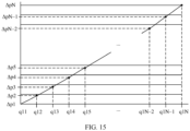
- the correspondence between an air flow value and an air pressure compensation value may be obtained in advance by analyzing pre-tested data, and may be pre-stored in the processor or a memory of the blood pressure measurement device before the blood pressure measurement device is delivered from a factory.
- the processor may obtain the correspondence between an air flow value and an air pressure compensation value in the following manner: first controlling the blood pressure measurement device to perform inflating when the airbag is removed, so that the air flow value detected by the flowmeter changes; obtaining a plurality of air pressure values detected by the barometric pressure sensor when the flowmeter detects a plurality of different air flow values, and using the obtained plurality of air pressure values as air pressure compensation values separately corresponding to the plurality of different air flow values; and finally, establishing the correspondence between an air flow value and an air pressure compensation value based on the plurality of different air flow values and the air pressure compensation values separately corresponding to the plurality of different air flow values.
- the processor may establish the correspondence between an air flow value and an air pressure compensation value in an interpolation method based on the plurality of different air flow values and the air pressure compensation values separately corresponding to the plurality of different air flow values.
- a process in which the blood pressure measurement device performs blood pressure measurement may include: controlling the driving apparatus to drive the air supply and exhaust apparatus to inflate the airbag, reading an air pressure value detected by the barometric pressure sensor and an air flow value detected by the flowmeter, obtaining an air pressure compensation value based on the air flow value detected by the flowmeter and a stored correspondence between an air flow value and an air pressure compensation value, and compensating, based on the obtained air pressure compensation value, the air pressure value detected by the barometric pressure sensor.
- the obtained air pressure compensation value may be subtracted from the air pressure value detected by the barometric pressure sensor, to obtain a compensated air pressure value.
- an operating parameter for example, a voltage, a current, or a frequency
- a driving circuit is controlled based on the compensated air pressure value to drive the air supply and exhaust apparatus to inflate the airbag.
- the foregoing procedure is performed at least once, for example, once, twice, three times, or four times, so that the compensated air pressure value meets a boost curve requirement for blood pressure measurement, thereby completing blood pressure measurement.
- the blood pressure measurement device may include a body, a processor, an airbag, an air supply and exhaust apparatus, a driving apparatus, a first barometric pressure sensor, and a second barometric pressure sensor.
- the body includes a cavity, and function modules or components of the blood pressure measurement device may be disposed in the cavity.
- the foregoing driving apparatus, the processor, the air supply and exhaust apparatus, the first barometric pressure sensor, and the second barometric pressure sensor may be disposed in the cavity.
- the airbag is fastened to an end of the body, and the airbag has an air cavity.
- the air supply and exhaust apparatus and the pressure sensor may be directly connected to the airbag through a corresponding air path or indirectly connected to the airbag.
- the blood pressure measurement device may further include an air path cavity, and the air path cavity is disposed in the cavity of the body.
- the air supply and exhaust apparatus may be connected to the air path cavity through the first air path
- the first barometric pressure sensor may be connected to the air path cavity through the second air path
- the air path cavity is connected to the air cavity of the airbag through a third air path.
- the processor may obtain the correspondence between a cavity air pressure value and an air pressure compensation value in the following manner: first controlling the blood pressure measurement device to perform inflating when the airbag is removed, so that a first air pressure value detected by the second barometric pressure sensor changes; obtaining a plurality of second air pressure values detected by the first barometric pressure sensor when the second barometric pressure sensor detects a plurality of different first air pressure values, and using the obtained plurality of second air pressure values as air pressure compensation values separately corresponding to the plurality of different first air pressure values; and finally, establishing the correspondence between a cavity air pressure value and an air pressure compensation value based on the plurality of different first air pressure values and the air pressure compensation values separately corresponding to the plurality of different first air pressure values.
- the blood pressure measurement device may include a body, a processor, an airbag, an air supply and exhaust apparatus, a driving apparatus, and a barometric pressure sensor.
- the body includes a cavity, and function modules or components of the blood pressure measurement device may be disposed in the cavity.
- the foregoing driving apparatus, the processor, the air supply and exhaust apparatus, the first barometric pressure sensor, and the second barometric pressure sensor may be disposed in the cavity.
- the airbag is fastened to an end of the body, and the airbag has an air cavity.
- the air supply and exhaust apparatus includes an air inlet path and an air outlet path, and the air supply and exhaust apparatus is connected to the air cavity of the airbag through a first air path.
- the correspondence between a driving state and an air pressure compensation value may be obtained in advance by analyzing pre-tested data, and is pre-stored in the processor of the blood pressure measurement device.
- the air pressure compensation value may be obtained based on the driving state and the stored correspondence between a driving state and an air pressure compensation value, and the air pressure value detected by the barometric pressure sensor is compensated based on the obtained air pressure compensation value, to obtain an accurate air pressure value in the airbag.
- a process in which the blood pressure measurement device performs blood pressure measurement may include: controlling the driving apparatus to drive the air supply and exhaust apparatus to inflate the airbag, reading an air pressure value detected by the barometric pressure sensor, obtaining an air pressure compensation value based on a driving state of the driving apparatus and a stored correspondence between a driving state and an air pressure compensation value, and compensating, based on the obtained air pressure compensation value, the air pressure value detected by the barometric pressure sensor.
- the obtained air pressure compensation value may be subtracted from the air pressure value detected by the barometric pressure sensor, to obtain a compensated air pressure value.
- an operating parameter for example, a voltage, a current, or a frequency
- a driving circuit is controlled based on the compensated air pressure value to drive the air supply and exhaust apparatus to inflate the airbag.
- the foregoing procedure is performed at least once, for example, once, twice, three times, or four times, so that the compensated air pressure value meets a boost curve requirement for blood pressure measurement, thereby completing blood pressure measurement.
- the blood pressure measurement device performs blood pressure measurement that, because the air supply and exhaust apparatus 4 is disposed in the cavity 101 of the body 1, in a process in which the air supply and exhaust apparatus 4 inflates/deflates the airbag 2, air pressure in the cavity 101 of the body 1 fluctuates.
- the air pressure fluctuation causes a difference between an air pressure value detected by the barometric pressure sensor 5 and an actual air pressure value in the airbag 2.
- the air pressure value detected by the barometric pressure sensor 5 is usually greater than an actual air pressure value inside the airbag 2.
- the air supply and exhaust apparatus 4 may be an air pump, and a volume of the air pump may be set based on a requirement of the airbag 2 of the blood pressure measurement apparatus for air supplying and exhausting and a size of the cavity 101 of the body 1.
- a volume of a body 1 of an existing smart watch with a blood pressure measurement function is small, space of a cavity 101 of the smart watch is also small. Therefore, a volume of an air pump disposed in the smart watch is also small.
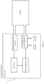
- the blood pressure measurement device may further include a driving apparatus 6 and a processor 7, and the processor 7 is electrically connected to the driving apparatus 6 and the barometric pressure sensor 5 separately.
- locations of the driving apparatus 6 and the processor 7 are not limited.
- the driving apparatus 6 and the processor 7 may be disposed in the cavity 101 of the body 1.
- the processor 7 is configured to control the barometric pressure sensor 5 and the driving apparatus 6.
- the driving apparatus 6 is configured to provide a driving force for an inflating/deflating process of the air supply and exhaust apparatus 4 under control of the processor 7.
- the driving apparatus 6 is not specifically limited either.
- the driving apparatus 6 may be a motor.
- error compensation may be performed on the air pressure value detected by the barometric pressure sensor 5, to reduce impact of air pressure in the cavity 101 of the body 1 of the blood pressure measurement device on blood pressure measurement of the barometric pressure sensor, and improve blood pressure measurement accuracy.
- the blood pressure measurement device may further include a flowmeter 9.
- the flowmeter 9 is configured to detect an air flow value of air flowing between the air supply and exhaust apparatus 4 and the airbag 2, or is configured to detect an air flow value of air flowing between the barometric pressure sensor 5 and the airbag 2.
- the blood pressure measurement device stores a correspondence between an air flow value and an air pressure compensation value.
- the correspondence may be stored in the processor 7 or a memory.
- the processor 7 may obtain a corresponding air pressure compensation value based on the air flow value detected by the flowmeter 9 and the stored correspondence between an air flow value and an air pressure compensation value, to compensate, based on the obtained air pressure compensation value, the air pressure value detected by the barometric pressure sensor 5.
- the driving apparatus 6 may be controlled based on a compensated air pressure value.
- the driving apparatus 6 drives, under control of the processor 7, the air supply and exhaust apparatus 4 to perform inflating or deflating, that is, the driving apparatus 6 may be configured to provide a driving force for the inflating/deflating process of the air supply and exhaust apparatus 4.
- the air flow value detected by the flowmeter 9 may represent the inflating/deflating amount of the air supply and exhaust apparatus 4, so that the processor 7 obtains the air pressure compensation value based on the air flow value detected by the flowmeter 9 and the stored correspondence between an air flow value and an air pressure compensation value, and compensates, based on the obtained air pressure compensation value, the air pressure value detected by the barometric pressure sensor 5, to obtain an accurate air pressure value in the airbag 2.
- the processor 7 obtains the air pressure compensation value based on the air flow value detected by the flowmeter 9 and the stored correspondence between an air flow value and an air pressure compensation value, and compensates, based on the obtained air pressure compensation value, the air pressure value detected by the barometric pressure sensor 5, to obtain an accurate air pressure value in the airbag 2.
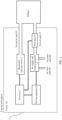
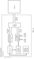
- FIG. 5 is a schematic diagram of a framework structure of a blood pressure measurement device according to another possible embodiment of this application.
- FIG. 6 is a schematic diagram of a framework structure of a blood pressure measurement device according to another possible embodiment of this application.
- the air path cavity 10 may be fastened, but not limited to, to a side that is of a side wall of the body 1 and that faces the cavity 101 through bonding or thread connection, to improve structure stability of the air path cavity 10.
- the air pressure compensation value may be obtained based on the air flow value detected by the flowmeter and the stored correspondence between an air flow value and an air pressure compensation value, and the air pressure value detected by the barometric pressure sensor is compensated based on the obtained air pressure compensation value, to obtain an accurate air pressure value in the airbag. In this way, impact of air pressure in the cavity on blood pressure measurement can be reduced, thereby improving blood pressure measurement accuracy.
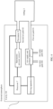
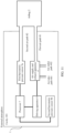
- FIG. 11 is a schematic diagram of a structure of a blood pressure measurement device according to another embodiment of this application.
- a structure of the blood pressure measurement device in this embodiment is different from that in any one of the foregoing embodiments.
- a main difference lies in that the blood pressure measurement device does not include a flowmeter, but includes two barometric pressure sensors, namely, a first barometric pressure sensor 5a and a second barometric pressure sensor 5b.
- both the first barometric pressure sensor 5a and the second barometric pressure sensor 5b are disposed in a cavity 101.
- the first barometric pressure sensor 5a may be connected to an air cavity of an airbag 2 through a second air path 82, to detect an air pressure value in an air cavity of the airbag.
- the air pressure compensation value may be obtained based on the air pressure value detected by the second barometric pressure sensor and the stored correspondence between an air pressure value and an air pressure compensation value, and the air pressure value detected by the first barometric pressure sensor is compensated based on the obtained air pressure compensation value, to obtain an accurate air pressure value in the airbag. In this way, impact of air pressure in the cavity on blood pressure measurement can be reduced, thereby improving blood pressure measurement accuracy.
Landscapes
- Health & Medical Sciences (AREA)
- Life Sciences & Earth Sciences (AREA)
- Cardiology (AREA)
- Vascular Medicine (AREA)
- Surgery (AREA)
- Animal Behavior & Ethology (AREA)
- Biomedical Technology (AREA)
- Heart & Thoracic Surgery (AREA)
- Medical Informatics (AREA)
- Molecular Biology (AREA)
- Physics & Mathematics (AREA)
- Engineering & Computer Science (AREA)
- General Health & Medical Sciences (AREA)
- Public Health (AREA)
- Veterinary Medicine (AREA)
- Biophysics (AREA)
- Pathology (AREA)
- Physiology (AREA)
- Ophthalmology & Optometry (AREA)
- Measuring Pulse, Heart Rate, Blood Pressure Or Blood Flow (AREA)
Applications Claiming Priority (2)
| Application Number | Priority Date | Filing Date | Title |
|---|---|---|---|
| CN202111591753.0A CN116327148B (zh) | 2021-12-23 | 2021-12-23 | 一种血压测量设备及电子设备 |
| PCT/CN2022/140802 WO2023116789A1 (zh) | 2021-12-23 | 2022-12-21 | 一种血压测量设备及电子设备 |
Publications (2)
| Publication Number | Publication Date |
|---|---|
| EP4393384A1 true EP4393384A1 (de) | 2024-07-03 |
| EP4393384A4 EP4393384A4 (de) | 2025-01-08 |
Family
ID=86877581
Family Applications (1)
| Application Number | Title | Priority Date | Filing Date |
|---|---|---|---|
| EP22910101.9A Pending EP4393384A4 (de) | 2021-12-23 | 2022-12-21 | Blutdruckmessvorrichtung und elektronische vorrichtung |
Country Status (4)
| Country | Link |
|---|---|
| US (1) | US20250311932A1 (de) |
| EP (1) | EP4393384A4 (de) |
| CN (1) | CN116327148B (de) |
| WO (1) | WO2023116789A1 (de) |
Families Citing this family (1)
| Publication number | Priority date | Publication date | Assignee | Title |
|---|---|---|---|---|
| CN119632525A (zh) * | 2023-09-15 | 2025-03-18 | 华为技术有限公司 | 血压测量方法、系统、电子设备及介质 |
Family Cites Families (9)
| Publication number | Priority date | Publication date | Assignee | Title |
|---|---|---|---|---|
| JP2009153843A (ja) * | 2007-12-27 | 2009-07-16 | Omron Healthcare Co Ltd | 血圧測定装置 |
| JP2010131247A (ja) * | 2008-12-05 | 2010-06-17 | Omron Healthcare Co Ltd | 血圧測定装置 |
| JP5565164B2 (ja) * | 2010-07-21 | 2014-08-06 | オムロンヘルスケア株式会社 | 電子血圧計 |
| JP5864118B2 (ja) * | 2011-03-29 | 2016-02-17 | フクダ電子株式会社 | 血圧計 |
| JP5821657B2 (ja) * | 2012-01-25 | 2015-11-24 | オムロンヘルスケア株式会社 | 測定装置および測定方法 |
| CN106793963B (zh) * | 2014-08-28 | 2020-07-21 | 皇家飞利浦有限公司 | 用于振荡法无创血压(nibp)测量的方法和用于nibp装置的控制单元 |
| GB2541368A (en) * | 2015-07-16 | 2017-02-22 | Diasolve Ltd | Fluid delivery apparatus |
| US10881307B1 (en) * | 2015-09-29 | 2021-01-05 | Apple Inc. | Devices and systems for correcting errors in blood pressure measurements |
| CN113143238B (zh) * | 2021-04-19 | 2022-07-12 | 研和智能科技(杭州)有限公司 | 一种基于压力信号和ppg信号的血压测量装置 |
-
2021
- 2021-12-23 CN CN202111591753.0A patent/CN116327148B/zh active Active
-
2022
- 2022-12-21 US US18/707,088 patent/US20250311932A1/en active Pending
- 2022-12-21 WO PCT/CN2022/140802 patent/WO2023116789A1/zh not_active Ceased
- 2022-12-21 EP EP22910101.9A patent/EP4393384A4/de active Pending
Also Published As
| Publication number | Publication date |
|---|---|
| CN116327148B (zh) | 2026-01-13 |
| US20250311932A1 (en) | 2025-10-09 |
| CN116327148A (zh) | 2023-06-27 |
| WO2023116789A1 (zh) | 2023-06-29 |
| EP4393384A4 (de) | 2025-01-08 |
Similar Documents
| Publication | Publication Date | Title |
|---|---|---|
| US20250152024A1 (en) | Blood pressure measurement device with a mems pump and control method for the same | |
| US7115104B2 (en) | High frequency chest wall oscillation apparatus | |
| EP4393384A1 (de) | Blutdruckmessvorrichtung und elektronische vorrichtung | |
| US10478077B2 (en) | Blood pressure meter | |
| US20150025400A1 (en) | Blood pressure meter | |
| US20110208068A1 (en) | Sphygmomanometer and charging unit for sphygmomanometer | |
| CN110198662B (zh) | 流体控制装置以及血压计 | |
| CN121370100A (zh) | 一种血压测量设备 | |
| CN115721281A (zh) | 血压测量穿戴设备及其充气方法 | |
| JP2010099384A (ja) | 血圧計 | |
| CN219289445U (zh) | 一种用于动态血压手表的压力传感器 | |
| CN116264962A (zh) | 一种脉搏波采集压力控制方法、装置及系统 | |
| CN115120211A (zh) | 一种血压手表和血压测量模块 | |
| CN217772332U (zh) | 血压测量模块及可穿戴智能设备 | |
| CN222467767U (zh) | 一种吸氧设备稳流装置 | |
| CN117959544B (zh) | 一种智能控制高精度供气系统 | |
| JP6374687B2 (ja) | 生体情報計測装置 | |
| WO2024189968A1 (ja) | 医療用機器 | |
| CN206026324U (zh) | 一种具有调节血压功能的动态血压测量装置 | |
| EP4691357A1 (de) | Elektromagnetisches ventil und wearable-vorrichtung | |
| CN121264998A (zh) | 一种腕式血压监测手表及智能防尘与除尘方法 |
Legal Events
| Date | Code | Title | Description |
|---|---|---|---|
| STAA | Information on the status of an ep patent application or granted ep patent |
Free format text: STATUS: THE INTERNATIONAL PUBLICATION HAS BEEN MADE |
|
| PUAI | Public reference made under article 153(3) epc to a published international application that has entered the european phase |
Free format text: ORIGINAL CODE: 0009012 |
|
| STAA | Information on the status of an ep patent application or granted ep patent |
Free format text: STATUS: REQUEST FOR EXAMINATION WAS MADE |
|
| 17P | Request for examination filed |
Effective date: 20240328 |
|
| AK | Designated contracting states |
Kind code of ref document: A1 Designated state(s): AL AT BE BG CH CY CZ DE DK EE ES FI FR GB GR HR HU IE IS IT LI LT LU LV MC ME MK MT NL NO PL PT RO RS SE SI SK SM TR |
|
| A4 | Supplementary search report drawn up and despatched |
Effective date: 20241206 |
|
| RIC1 | Information provided on ipc code assigned before grant |
Ipc: A61B 5/021 20060101ALI20241202BHEP Ipc: A61B 5/00 20060101ALI20241202BHEP Ipc: A61B 5/0225 20060101ALI20241202BHEP Ipc: A61B 5/022 20060101AFI20241202BHEP |
|
| DAV | Request for validation of the european patent (deleted) | ||
| DAX | Request for extension of the european patent (deleted) | ||
| GRAP | Despatch of communication of intention to grant a patent |
Free format text: ORIGINAL CODE: EPIDOSNIGR1 |
|
| STAA | Information on the status of an ep patent application or granted ep patent |
Free format text: STATUS: GRANT OF PATENT IS INTENDED |