EP4392598B1 - Vorrichtung eines festoxidstapel vom typ soec/sofc und spannvorrichtung mit heizplatte - Google Patents
Vorrichtung eines festoxidstapel vom typ soec/sofc und spannvorrichtung mit heizplatte Download PDFInfo
- Publication number
- EP4392598B1 EP4392598B1 EP22789266.8A EP22789266A EP4392598B1 EP 4392598 B1 EP4392598 B1 EP 4392598B1 EP 22789266 A EP22789266 A EP 22789266A EP 4392598 B1 EP4392598 B1 EP 4392598B1
- Authority
- EP
- European Patent Office
- Prior art keywords
- clamping
- housing
- clamping plates
- assembly
- assembly according
- Prior art date
- Legal status (The legal status is an assumption and is not a legal conclusion. Google has not performed a legal analysis and makes no representation as to the accuracy of the status listed.)
- Active
Links
Images


Classifications
-
- H—ELECTRICITY
- H01—ELECTRIC ELEMENTS
- H01M—PROCESSES OR MEANS, e.g. BATTERIES, FOR THE DIRECT CONVERSION OF CHEMICAL ENERGY INTO ELECTRICAL ENERGY
- H01M8/00—Fuel cells; Manufacture thereof
- H01M8/24—Grouping of fuel cells, e.g. stacking of fuel cells
- H01M8/2465—Details of groupings of fuel cells
- H01M8/247—Arrangements for tightening a stack, for accommodation of a stack in a tank or for assembling different tanks
- H01M8/248—Means for compression of the fuel cell stacks
-
- C—CHEMISTRY; METALLURGY
- C25—ELECTROLYTIC OR ELECTROPHORETIC PROCESSES; APPARATUS THEREFOR
- C25B—ELECTROLYTIC OR ELECTROPHORETIC PROCESSES FOR THE PRODUCTION OF COMPOUNDS OR NON-METALS; APPARATUS THEREFOR
- C25B1/00—Electrolytic production of inorganic compounds or non-metals
- C25B1/01—Products
- C25B1/02—Hydrogen or oxygen
- C25B1/04—Hydrogen or oxygen by electrolysis of water
- C25B1/042—Hydrogen or oxygen by electrolysis of water by electrolysis of steam
-
- C—CHEMISTRY; METALLURGY
- C25—ELECTROLYTIC OR ELECTROPHORETIC PROCESSES; APPARATUS THEREFOR
- C25B—ELECTROLYTIC OR ELECTROPHORETIC PROCESSES FOR THE PRODUCTION OF COMPOUNDS OR NON-METALS; APPARATUS THEREFOR
- C25B15/00—Operating or servicing cells
- C25B15/02—Process control or regulation
- C25B15/023—Measuring, analysing or testing during electrolytic production
-
- C—CHEMISTRY; METALLURGY
- C25—ELECTROLYTIC OR ELECTROPHORETIC PROCESSES; APPARATUS THEREFOR
- C25B—ELECTROLYTIC OR ELECTROPHORETIC PROCESSES FOR THE PRODUCTION OF COMPOUNDS OR NON-METALS; APPARATUS THEREFOR
- C25B9/00—Cells or assemblies of cells; Constructional parts of cells; Assemblies of constructional parts, e.g. electrode-diaphragm assemblies; Process-related cell features
- C25B9/05—Pressure cells
-
- C—CHEMISTRY; METALLURGY
- C25—ELECTROLYTIC OR ELECTROPHORETIC PROCESSES; APPARATUS THEREFOR
- C25B—ELECTROLYTIC OR ELECTROPHORETIC PROCESSES FOR THE PRODUCTION OF COMPOUNDS OR NON-METALS; APPARATUS THEREFOR
- C25B9/00—Cells or assemblies of cells; Constructional parts of cells; Assemblies of constructional parts, e.g. electrode-diaphragm assemblies; Process-related cell features
- C25B9/60—Constructional parts of cells
- C25B9/67—Heating or cooling means
-
- C—CHEMISTRY; METALLURGY
- C25—ELECTROLYTIC OR ELECTROPHORETIC PROCESSES; APPARATUS THEREFOR
- C25B—ELECTROLYTIC OR ELECTROPHORETIC PROCESSES FOR THE PRODUCTION OF COMPOUNDS OR NON-METALS; APPARATUS THEREFOR
- C25B9/00—Cells or assemblies of cells; Constructional parts of cells; Assemblies of constructional parts, e.g. electrode-diaphragm assemblies; Process-related cell features
- C25B9/70—Assemblies comprising two or more cells
- C25B9/73—Assemblies comprising two or more cells of the filter-press type
- C25B9/75—Assemblies comprising two or more cells of the filter-press type having bipolar electrodes
-
- C—CHEMISTRY; METALLURGY
- C25—ELECTROLYTIC OR ELECTROPHORETIC PROCESSES; APPARATUS THEREFOR
- C25B—ELECTROLYTIC OR ELECTROPHORETIC PROCESSES FOR THE PRODUCTION OF COMPOUNDS OR NON-METALS; APPARATUS THEREFOR
- C25B9/00—Cells or assemblies of cells; Constructional parts of cells; Assemblies of constructional parts, e.g. electrode-diaphragm assemblies; Process-related cell features
- C25B9/70—Assemblies comprising two or more cells
- C25B9/73—Assemblies comprising two or more cells of the filter-press type
- C25B9/77—Assemblies comprising two or more cells of the filter-press type having diaphragms
-
- H—ELECTRICITY
- H01—ELECTRIC ELEMENTS
- H01M—PROCESSES OR MEANS, e.g. BATTERIES, FOR THE DIRECT CONVERSION OF CHEMICAL ENERGY INTO ELECTRICAL ENERGY
- H01M8/00—Fuel cells; Manufacture thereof
- H01M8/04—Auxiliary arrangements, e.g. for control of pressure or for circulation of fluids
- H01M8/04007—Auxiliary arrangements, e.g. for control of pressure or for circulation of fluids related to heat exchange
- H01M8/04037—Electrical heating
-
- H—ELECTRICITY
- H01—ELECTRIC ELEMENTS
- H01M—PROCESSES OR MEANS, e.g. BATTERIES, FOR THE DIRECT CONVERSION OF CHEMICAL ENERGY INTO ELECTRICAL ENERGY
- H01M8/00—Fuel cells; Manufacture thereof
- H01M8/04—Auxiliary arrangements, e.g. for control of pressure or for circulation of fluids
- H01M8/04007—Auxiliary arrangements, e.g. for control of pressure or for circulation of fluids related to heat exchange
- H01M8/04067—Heat exchange or temperature measuring elements, thermal insulation, e.g. heat pipes, heat pumps, fins
-
- H—ELECTRICITY
- H01—ELECTRIC ELEMENTS
- H01M—PROCESSES OR MEANS, e.g. BATTERIES, FOR THE DIRECT CONVERSION OF CHEMICAL ENERGY INTO ELECTRICAL ENERGY
- H01M8/00—Fuel cells; Manufacture thereof
- H01M8/04—Auxiliary arrangements, e.g. for control of pressure or for circulation of fluids
- H01M8/04223—Auxiliary arrangements, e.g. for control of pressure or for circulation of fluids during start-up or shut-down; Depolarisation or activation, e.g. purging; Means for short-circuiting defective fuel cells
- H01M8/04268—Heating of fuel cells during the start-up of the fuel cells
-
- H—ELECTRICITY
- H01—ELECTRIC ELEMENTS
- H01M—PROCESSES OR MEANS, e.g. BATTERIES, FOR THE DIRECT CONVERSION OF CHEMICAL ENERGY INTO ELECTRICAL ENERGY
- H01M8/00—Fuel cells; Manufacture thereof
- H01M8/04—Auxiliary arrangements, e.g. for control of pressure or for circulation of fluids
- H01M8/04298—Processes for controlling fuel cells or fuel cell systems
- H01M8/04313—Processes for controlling fuel cells or fuel cell systems characterised by the detection or assessment of variables; characterised by the detection or assessment of failure or abnormal function
- H01M8/0432—Temperature; Ambient temperature
-
- H—ELECTRICITY
- H01—ELECTRIC ELEMENTS
- H01M—PROCESSES OR MEANS, e.g. BATTERIES, FOR THE DIRECT CONVERSION OF CHEMICAL ENERGY INTO ELECTRICAL ENERGY
- H01M8/00—Fuel cells; Manufacture thereof
- H01M8/10—Fuel cells with solid electrolytes
- H01M8/12—Fuel cells with solid electrolytes operating at high temperature, e.g. with stabilised ZrO2 electrolyte
-
- H—ELECTRICITY
- H01—ELECTRIC ELEMENTS
- H01M—PROCESSES OR MEANS, e.g. BATTERIES, FOR THE DIRECT CONVERSION OF CHEMICAL ENERGY INTO ELECTRICAL ENERGY
- H01M8/00—Fuel cells; Manufacture thereof
- H01M8/24—Grouping of fuel cells, e.g. stacking of fuel cells
- H01M8/241—Grouping of fuel cells, e.g. stacking of fuel cells with solid or matrix-supported electrolytes
- H01M8/2425—High-temperature cells with solid electrolytes
- H01M8/2432—Grouping of unit cells of planar configuration
-
- H—ELECTRICITY
- H01—ELECTRIC ELEMENTS
- H01M—PROCESSES OR MEANS, e.g. BATTERIES, FOR THE DIRECT CONVERSION OF CHEMICAL ENERGY INTO ELECTRICAL ENERGY
- H01M8/00—Fuel cells; Manufacture thereof
- H01M8/10—Fuel cells with solid electrolytes
- H01M8/12—Fuel cells with solid electrolytes operating at high temperature, e.g. with stabilised ZrO2 electrolyte
- H01M2008/1293—Fuel cells with solid oxide electrolytes
-
- Y—GENERAL TAGGING OF NEW TECHNOLOGICAL DEVELOPMENTS; GENERAL TAGGING OF CROSS-SECTIONAL TECHNOLOGIES SPANNING OVER SEVERAL SECTIONS OF THE IPC; TECHNICAL SUBJECTS COVERED BY FORMER USPC CROSS-REFERENCE ART COLLECTIONS [XRACs] AND DIGESTS
- Y02—TECHNOLOGIES OR APPLICATIONS FOR MITIGATION OR ADAPTATION AGAINST CLIMATE CHANGE
- Y02E—REDUCTION OF GREENHOUSE GAS [GHG] EMISSIONS, RELATED TO ENERGY GENERATION, TRANSMISSION OR DISTRIBUTION
- Y02E60/00—Enabling technologies; Technologies with a potential or indirect contribution to GHG emissions mitigation
- Y02E60/30—Hydrogen technology
- Y02E60/50—Fuel cells
Definitions
- the present invention relates to the general field of high temperature electrolysis (HTE), in particular high temperature steam electrolysis (HTSE), respectively designated by the English names “High Temperature Electrolysis” (HTE) and “High Temperature Steam Electrolysis” (HTSE), of the electrolysis of carbon dioxide (CO 2 ), or even of the co-electrolysis of water vapor and carbon dioxide (CO 2 ) at high temperature.
- HTE high temperature electrolysis
- HTSE high temperature steam electrolysis
- CO 2 carbon dioxide
- CO 2 co-electrolysis
- the invention relates to the field of high-temperature solid oxide electrolysers, usually designated by the acronym SOEC (for “Solid Oxide Electrolysis Cell” in English).
- SOEC Solid Oxide Electrolysis Cell
- SOFC Solid Oxide Fuel Cells
- the invention refers to the field of solid oxide stacks of the SOEC/SOFC type operating at high temperature.
- the invention relates to an assembly comprising a stack of solid oxide cells of the SOEC/SOFC type and a clamping system comprising at least one removable and interchangeable heating plate, as well as an associated manufacturing method.
- the following description favors the operation of a high-temperature solid oxide electrolyzer of the SOEC type carrying out the electrolysis of water vapor.
- this operation is applicable to the electrolysis of carbon dioxide (CO 2 ), or even the co-electrolysis of high-temperature water vapor with carbon dioxide (CO 2 ).
- this operation is transposable to the case of a high-temperature solid oxide fuel cell of the SOFC type.
- a high-temperature solid oxide electrolyzer of the SOEC type consists of a stack of elementary patterns, each comprising a solid oxide electrolysis cell, or electrochemical cell, consisting of three anode/electrolyte/cathode layers superimposed on each other, and interconnection plates made of metal alloys, also called bipolar plates or interconnectors. Each electrochemical cell is sandwiched between two interconnection plates.
- a high-temperature solid oxide electrolyzer of the SOEC type is then an alternating stack of electrochemical cells and interconnectors.
- a high-temperature solid oxide fuel cell of the SOFC type consists of the same type of stack of elementary patterns. Since this high-temperature technology is reversible, the same stack can operate in electrolysis mode and produce hydrogen and oxygen from water and electricity, or in fuel cell mode and produce electricity from hydrogen and oxygen.
- Each electrochemical cell corresponds to an electrolyte/electrode assembly, which is typically a multilayer ceramic assembly whose electrolyte is formed by a central ion-conducting layer, this layer being solid, dense and waterproof, and sandwiched between the two porous layers forming the electrodes. It should be noted that additional layers may exist, but which only serve to improve one or more of the layers already described.
- the electrical and fluidic interconnection devices are electronic conductors which ensure, from an electrical point of view, the connection of each electrochemical cell of elementary pattern in the stack of elementary patterns, guaranteeing the electrical contact between one face and the cathode of a cell and between the other face and the anode of the following cell, and from a fluidic point of view, the supply of reactants and the evacuation of products for each of the cells.
- the interconnectors thus ensure the functions of supplying and collecting electric current and delimiting gas circulation compartments, for distribution and/or collection.
- the main function of the interconnectors is to ensure the passage of electric current but also the circulation of gases in the vicinity of each cell (namely: injected water vapor, hydrogen and oxygen extracted for EHT electrolysis; air and fuel including injected hydrogen and extracted water for a SOFC cell), and to separate the anode and cathode compartments of two adjacent cells, which are the gas circulation compartments on the anode and cathode sides of the cells respectively.
- the cathode compartment contains water vapor and hydrogen, the product of the electrochemical reaction, while the anode compartment contains a drain gas, if present, and oxygen, another product of the electrochemical reaction.
- the anode compartment contains the fuel, while the cathode compartment contains the fuel.
- HTE high-temperature water vapor electrolysis
- H2O water vapor
- this Dissociation produces hydrogen gas (H 2 ) and oxygen ions (O 2- ).
- the hydrogen (H 2 ) is collected and discharged at the outlet of the hydrogen compartment.
- the oxygen ions (O 2- ) migrate through the electrolyte and recombine into oxygen (O 2 ) at the interface between the electrolyte and the oxygen electrode (anode).
- a drain gas such as air, can flow past the anode and thus collect the oxygen generated in gaseous form at the anode.
- SOFC solid oxide fuel cell
- air oxygen
- the oxygen in the air will dissociate into O 2- ions.
- These ions will migrate in the electrolyte from the cathode to the anode to oxidize the hydrogen and form water with simultaneous production of electricity.
- the water vapor is in the dihydrogen (H 2 ) compartment. Only the polarity is reversed.
- Figure 1 represents a schematic view showing the operating principle of a high-temperature solid oxide electrolyzer of the SOEC type.
- the function of such an electrolyzer is to transform water vapor into hydrogen and oxygen according to the following electrochemical reaction: 2 H 2 O ⁇ 2 H 2 + O 2 .
- each elementary electrolysis cell 1 is formed of a cathode 2 and an anode 4, placed on either side of a solid electrolyte 3.
- the two electrodes (cathode and anode) 2 and 4 are electronic and/or ionic conductors, made of porous material, and the electrolyte 3 is gas-tight, electronically insulating and ionically conductive.
- the electrolyte 3 may in particular be an anionic conductor, more precisely an anionic conductor of O 2- ions and the electrolyser is then called an anionic electrolyser, as opposed to protonic electrolytes (H + ).
- Electrochemical reactions take place at the interface between each of the electronic conductors and the ionic conductor.
- the half-reaction is as follows: 2 H 2 O + 4 e - ⁇ 2 H 2 + 2 O 2- .
- the half-reaction is as follows: 2 O 2- ⁇ O 2 + 4 e - .
- Electrolyte 3, intercalated between the two electrodes 2 and 4, is the place of migration of the O 2- ions under the effect of the electric field created by the potential difference imposed between the anode 4 and the cathode 2.
- the water vapor at the cathode inlet can be accompanied by hydrogen H 2 and the hydrogen produced and recovered at the outlet can be accompanied by water vapor.
- a draining gas such as air, can also be injected at the inlet on the anode side to evacuate the oxygen produced.
- the injection of a draining gas has the additional function of acting as a thermal regulator.
- An elementary electrolyzer, or electrolysis reactor consists of an elementary cell as described above, with a cathode 2, an electrolyte 3, and an anode 4, and two interconnectors which provide the electrical and fluid distribution functions.
- a high-temperature solid oxide electrolyser of the SOEC type thus comprises at least one, generally a plurality of electrolysis cells stacked on top of each other, each elementary cell being formed of an electrolyte, a cathode and an anode, the electrolyte being intercalated between the anode and the cathode.
- the fluidic and electrical interconnection devices which are in electrical contact with one or more electrodes generally provide the functions of supplying and collecting electric current and delimit one or more gas circulation compartments.
- the so-called cathode compartment has the function of distributing the electric current and water vapor as well as recovering hydrogen at the cathode in contact.
- the so-called anode compartment has the function of distributing the electric current as well as recovering the oxygen produced at the anode in contact, possibly using a draining gas.
- FIG. 2 represents an exploded view of elementary patterns of a high-temperature solid oxide electrolyzer of the SOEC type according to the prior art.
- This electrolyzer comprises a plurality of elementary electrolysis cells C1, C2, of the solid oxide cell (SOEC) type, stacked alternately with interconnectors 5.
- Each cell C1, C2 consists of a cathode 2.1, 2.2 and an anode (only the anode 4.2 of cell C2 is shown), between which an electrolyte is arranged (only the electrolyte 3.2 of cell C2 is shown).
- the interconnector 5 is a metal alloy component that ensures the separation between the cathode 50 and anode 51 compartments, defined by the volumes between the interconnector 5 and the adjacent cathode 2.1 and between the interconnector 5 and the adjacent anode 4.2 respectively. It also ensures the distribution of gases to the cells.
- the injection of water vapor into each elementary pattern is done in the cathode compartment 50.
- the collection of the hydrogen produced and the residual water vapor at the cathode 2.1, 2.2 is carried out in the cathode compartment 50 downstream of the cell C1, C2 after dissociation of the water vapor by the latter.
- the collection of the oxygen produced at the anode 4.2 is carried out in the anode compartment 51 downstream of the cell C1, C2 after dissociation of the water vapor by the latter.
- the interconnector 5 ensures the passage of current between cells C1 and C2 by direct contact with the adjacent electrodes, i.e. between the anode 4.2 and the cathode 2.1.
- the incoming and outgoing gases in a high temperature electrolysis stack (SOEC) or fuel cell stack (SOFC) operating at high temperature can be managed through devices such as that illustrated with reference to Figure 3
- the device 13 thus comprises cold parts PF and hot parts PC, the latter comprising the furnace bottom 11, the furnace bell 10, a loop tube 12 for managing the gas inlets and outlets and the stack 20, also called a “stack”, of high-temperature electrolysis (SOEC) or fuel cell (SOFC).
- This PnP system with integrated heating units allows the rapid installation of the stack within a so-called "Hot-Box" system, then consisting only of an insulated and compact enclosure, and its operation without having to manage its tightening in operation at high temperature, despite the differential expansions of the different components, and the improvement of the thermal efficiency of the system and consequently its performance. This also allows for a gain in compactness in the heating zone since a resistive furnace is no longer necessary.
- an example of an assembly 80 has thus been illustrated comprising a stack 20 of solid oxides of the SOEC/SOFC type and a clamping system 60.
- This stack 20 comprises a plurality of electrochemical cells 41 each formed of a cathode, an anode and an electrolyte intercalated between the cathode and the anode, and a plurality of intermediate interconnectors 42 each arranged between two adjacent electrochemical cells 41.
- This assembly of electrochemical cells 41 and intermediate interconnectors 42 is also referred to as a “stack”.
- the stack 20 comprises an upper end plate 43 and a lower end plate 44, respectively also called upper stack end plate 43 and lower stack end plate 44, between which the plurality of electrochemical cells 41 and the plurality of intermediate interconnectors 42 are sandwiched, or between which the stack is located.
- the assembly 80 also comprises a clamping system 60 for the stack 20 of solid oxides of the SOEC/SOFC type, comprising an upper clamping plate 45 and a lower clamping plate 46, between which the stack 20 of solid oxides of the SOEC/SOFC type is clamped.
- a clamping system 60 for the stack 20 of solid oxides of the SOEC/SOFC type, comprising an upper clamping plate 45 and a lower clamping plate 46, between which the stack 20 of solid oxides of the SOEC/SOFC type is clamped.
- Each clamping plate 45, 46 of the clamping system 60 comprises four clamping orifices 54.
- clamping system 60 further comprises four clamping rods 55, or tie rods, extending through a clamping hole 54 of the upper clamping plate 45 and through a corresponding clamping hole 54 of the lower clamping plate 46 to allow the upper 45 and lower 46 clamping plates to be assembled together.
- the clamping system 60 further comprises clamping means 56, 57, 58 at each clamping orifice 54 of the upper 45 and lower 46 clamping plates cooperating with the clamping rods 55 to allow the upper 45 and lower 46 clamping plates to be assembled together.
- the clamping means comprise, at each clamping orifice 54 of the upper clamping plate 45, a first clamping nut 56 cooperating with the corresponding clamping rod 55 inserted through the clamping orifice 54.
- the clamping means comprise, at each clamping orifice 54 of the lower clamping plate 46, a second clamping nut 57 associated with a clamping washer 58, these cooperating with the corresponding clamping rod 55 inserted through the clamping orifice 54.
- the clamping washer 58 is located between the second clamping nut 57 and the lower clamping plate 46.
- heating elements of the heating cord type are integrated into the two upper and lower clamping plates, which are about 30 mm thick, made of refractory austenitic steel, type AISI 310, by machining and brazing.
- the heating elements integrated into the dense metal components in direct contact with the stack thus significantly improve heat transfer losses, which then occur by conduction without disturbance and uniformly across the contact areas. This allows for excellent thermal homogeneity between the upper and lower plates, and by extension good overall homogeneity of the stack, and increased responsiveness of the heating elements to the temperature setpoint for the electrolyser. This results in better thermal management of the entire system. Since the heating is integrated, the insulation can be modulated to the shapes of the stack, further limiting radiation to the outside. Such heat transfer efficiency of the heating elements then makes it possible to reduce the power supplied to the system by at least 100 W to operate at temperatures of around 600 to 1000°C. The temperature measured in the insulated enclosure follows a rising ramp almost identical to that of the plates, which is also a very good sign for the thermal control of the "Hot-Box".
- the invention aims to at least partially remedy the needs mentioned above and the drawbacks relating to the achievements of the prior art.
- the invention it may be possible to maintain the interests associated with the integration of heating elements in the thick clamping plates, which makes it possible to improve the thermal efficiency of the SOEC/SOFC type stack while minimizing heat losses and maintaining the same dimensioning of the elements of the autonomous clamping system described above.
- the principle of the invention makes it possible to make the heating element(s) removable and interchangeable, in particular in the event of their malfunction.
- the assembly according to the invention may also include one or more of the following characteristics taken in isolation or in any possible technical combination.
- Said housing and said at least one heating plate may have a substantially parallelepiped shape, in particular a block shape or a cubic shape.
- said housing may be formed, in the thickness of said at least one of the upper and lower clamping plates, centrally, at an equal distance from the upper and lower main faces, and at an equal distance from the clamping holes, between the clamping holes.
- the thickness of said housing may be between 5 mm and 10 mm, in particular of the order of 8 mm.
- the width of said housing may be between 20 mm and 86 mm, in particular of the order of 86 mm.
- said at least one heating plate may comprise a heating resistor whose maximum power is at least 1200 W.
- Said at least one heating plate may be made of ceramic or metal alloy, in particular stainless steel or nickel-based alloy, being in particular treated with an aluminizing coating.
- a clearance may be present between the external surface of said at least one heating plate and the internal surface of said housing, the dimension of which may be between 0.2 and 0.5 mm.
- said at least one of the upper and lower clamping plates may comprise at least one internal groove formed in the thickness of said at least one of the upper and lower clamping plates, and extending substantially parallel to the upper and lower faces thereof, and at least one end of which opens onto the lateral face of said at least one of the upper and lower clamping plates.
- the assembly may then comprise at least one thermocouple device inserted into said at least one internal groove.
- said at least one internal groove may comprise a first internal safety groove and a second internal regulation groove.
- Said at least one thermocouple device may comprise a first safety thermocouple device inserted in the first internal groove and a second regulation thermocouple device inserted in the second internal groove.
- the assembly may include an upper end plate and a lower end plate, between which the plurality of electrochemical cells and the plurality of intermediate interconnectors are sandwiched.
- said at least one of the upper and lower clamping plates can advantageously be manufactured by an additive manufacturing technique, being in particular made of refractory austenitic steel, in particular of the AISI 310 type.
- said at least one of the upper and lower clamping plates may have a thickness of between 20 and 30 mm, in particular of the order of 25 mm.
- the invention also relates, according to another of its aspects, to a method of manufacturing an assembly as defined above, characterized in that it comprises the step of producing said housing in said at least one of the upper and lower clamping plates.
- the step of producing said housing may, for example, include production by electroerosion by sinking and/or by additive manufacturing.
- the operating temperature of a high-temperature SOEC/SOFC stack is also typically between 600 and 1000°C.
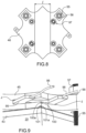
- each upper 45 and lower 46 clamping plate comprises a housing 90.
- the characteristics of such housings 90 are better seen with reference to figures 6 to 8 .
- Each housing 90 is formed in the thickness e p of each upper 45 and lower 46 clamping plate. It comprises a first end 90a and a second end 90b, opposite one another, which both open onto the lateral face FL of each clamping plate 45, 46.
- the housing 90 is formed inside the corresponding clamping plate 45, 46, passing through it along a longitudinal axis passing through the middle of the plate. It is therefore centered inside the clamping plate 45, 46.
- the housing 90 is formed at an equal distance from the clamping holes 54, between them.
- the housing 90 is formed at an equal distance from the gas inlet and/or outlet passage holes 97.
- Each housing 90 is thus intended to receive a heating plate 95, as visible in the Figure 5 .
- Each hot plate 95 is powered via power cords 98 visible on the Figure 5
- the positioning of the heating plates 95, provided with such electrical inlets in the form of cables 98, can be done so that these are located outside the side generating the least disturbance.
- each housing 90 and each heating plate 95 are in a substantially parallelepiped shape, and in particular here a shape sensitive to paving but it could also be a cubic shape, or even another shape.
- the invention therefore allows the use of removable and interchangeable heating plates. Also, in the event of deterioration of a heating plate, it can be easily replaced.
- the dimensions of the housing 90 and the heating plate 95 may vary according to different needs and in particular according to the nature of the heating plates used.
- the thickness e l of the housing 90 is between 5 mm and 10 mm, being for example here of the order of 8 mm, and the width l of the housing 90 is between 20 mm and 86 mm, being for example here of the order of 86 mm.
- the thickness e' of the heating plate 95 is between 5 mm and 10 mm, being for example here of the order of 5 mm
- the width l' of the heating plate 95, in particular its heating surface is between 20 mm and 86 mm, being for example here of the order of 84 mm
- the length L' of the heating plate 95, in particular its heating surface is between 210 mm and 220 mm, being for example here of the order of 260 mm.
- the housings 90, or openings, formed in the upper 45 and lower 46 clamping plates can be produced in different ways. In particular, they can be obtained by a die-sinking electroerosion process (or EDM for “Electrical Discharge Machining” in English) and/or by an additive manufacturing process, including in particular 3D printing.
- die-sinking EDM is a machining process that involves removing material from a part using electrical discharges. It is also known as spark machining. This technique is characterized by its ability to machine all electrically conductive materials, such as metals, alloys, carbides, graphite, etc., regardless of their hardness. This machining process involves passing a current through a dielectric to generate a "bubble" of vapor or vacuum that ionizes and reabsorbs by imploding, resulting in the destruction of the material. This destruction, micro-implosion, causes the spark. The high-intensity current ionizes a channel through the dielectric.
- a disruptive discharge then occurs, from the electrode to the workpiece, damaging it very locally, of the order of a few ⁇ m 2 .
- the dielectric then cools the damaged particles which fall into the machine tank in the form of a sludge (microparticles of material and dielectric).
- additive manufacturing technology allows, from a digital file model and with the help of a machine using a process such as extrusion or solidification of metal powder, polymer and polymer thread, to create, step by step, an object.
- This is called "layer by layer” printing.
- 3D printing boils down to a deposition of the molten material, selective filtering using an energy source (laser, resistors, electron beams, or ultraviolet light) which allows the object to be assembled and finally the solidification of the material during the cooling period, except in the case of stereolithography where a chemical phenomenon of polymerization occurs on photocrosslinkable resins.
- the machine prints each layer sequentially, one on top of the other, thus building a real object inside the machine's construction chamber.
- the 95 heating plates include heating resistors whose maximum power is at least 1200 W. Thus, they can reach a power of approximately 1200 W ⁇ 10% under 230 V, which corresponds to a maximum temperature of the hot zone of 1000°C with good insulation and suitable regulation, thus making it possible to cover the power dissipated by the insulated enclosure.
- the 95 heating plates can be obtained commercially, in particular through companies specializing in high temperatures.
- Heating plates can preferably be made of ceramic. Various dimensions and sizes can be produced. Such heating plates can have a hot zone with an operating range up to 1000°C and a cold zone in the contact zone up to 600°C, which can be protected by ceramic wool sheathing. However, large flat heating plates can be manufactured without a cold zone. The special properties and low mass of the ceramic material can enable fast heating rates, uniform temperature distribution, and precise control. The high emissivity and broad emission spectrum of thermal radiation can make the ceramic material, obtained from silicon nitride, an ideal radiant heating element. A power of 15 W/cm 2 at 1000°C can be achieved.
- Heating plates can also be made of a metal alloy.
- they can be made of stainless steel, for example 316L stainless steel, or a nickel-based alloy, in particular Inconel ® , for example Inconel ® 600.
- they are advantageously treated with an aluminizing coating on their surfaces so as not to weld with the surfaces with which they might be in contact.
- the heating plates may be made of heating cables, in particular composed of a heating core with mineral insulation, for example of the 96-99% magnesium oxide (MgO) type, under an Inconel ® 600 sheath and integrated cold terminations, illustrated by the reference 95t on the Figure 5
- the heating core can have a diameter between 1 and 2 mm at ⁇ 0.05 mm over a given length.
- a clearance J is present between the external surface of the heating plate 95 and the internal surface of the housing 90.
- This clearance J may in particular have a dimension of between 0.2 and 0.5 mm.
- the heating plate 95 When inserting the heating plate 95 into its housing 90, it can be coated with thermal grease, which will have the effect of filling the gap J and achieving good heat transfer.
- Each clamping plate 45, 46 is for example made of refractory material of the 310s stainless steel type. Its coefficient of thermal expansion at 850°C is for example 18.2 (in 10 -6 .K -1 ), which gives a displacement of 0.012 mm for a width l of 86 mm of the housing 90. It should be noted that the expansion of the silicon nitride (ceramic) is negligible for a width of 86 mm.
- Table 1 below presents data of interest for ceramic materials that can be used for the manufacture of 95 heating plates, and in particular the coefficients of thermal expansion.
- each clamping plate 45, 46 has internal grooves 100, 101, for example made in the form of holes, in order to insert two thermocouple devices per plate 45, 46.
- a first internal safety groove 100 and a second internal regulation groove 101 are formed in the upper clamping plate 45, respectively allowing the insertion of a first safety thermocouple device and a second thermocouple device.
- the first safety thermocouple device of the heating plate 95 is placed as close as possible to the area to be controlled, namely as close as possible to the heating resistor in order to avoid its overheating and deterioration.
- the second regulating thermocouple device of the heating plate 95 is located in the area of interest making it possible to obtain information on the heat transfer to the stack 20, or stack.
- a housing 90 of 86 mm x 8 mm in the middle of the clamping plate was chosen. It is then necessary to verify that under a clamping force of 500 N per tie rod, the deflection of the clamping plate allows the heating plate 95 to be inserted or removed when the stack 20 is under clamping.
- the calculation was carried out at 800°C with the material of the clamping plate 45, 46 being 310S steel.
Landscapes
- Chemical & Material Sciences (AREA)
- Engineering & Computer Science (AREA)
- Electrochemistry (AREA)
- Chemical Kinetics & Catalysis (AREA)
- Organic Chemistry (AREA)
- Metallurgy (AREA)
- Materials Engineering (AREA)
- General Chemical & Material Sciences (AREA)
- Life Sciences & Earth Sciences (AREA)
- Sustainable Energy (AREA)
- Sustainable Development (AREA)
- Manufacturing & Machinery (AREA)
- Analytical Chemistry (AREA)
- Automation & Control Theory (AREA)
- Inorganic Chemistry (AREA)
- Fuel Cell (AREA)
- Electrolytic Production Of Non-Metals, Compounds, Apparatuses Therefor (AREA)
Claims (14)
- Baugruppe (80), umfassend:- einen Stapel (20) von Festoxidzellen des SOEC/SOFC-Typs, die bei hoher Temperatur arbeiten, umfassend:- eine Vielzahl von elektrochemischen Zellen (41), die jeweils aus einer Kathode, einer Anode und einem zwischen Kathode und Anode eingelegten Elektrolyt gebildet sind, und eine Vielzahl von Zwischenverbindern (42), die jeweils zwischen zwei benachbarten elektrochemischen Zellen (41) angeordnet sind,- ein Spannsystem (60) des Stapels (20) von Festoxidzellen des SOEC/SOFC-Typs, umfassend eine obere Spannplatte (45) und eine untere Spannplatte (46), zwischen denen der Stapel (20) von Festoxidzellen des SOEC/SOFC-Typs eingespannt ist, wobei jede Spannplatte (45, 46) mindestens zwei Spannöffnungen (54) umfasst, wobei das Spannsystem (60) ferner Folgendes umfasst:- mindestens zwei Spannstangen (55), die dazu bestimmt sind, sich jeweils durch eine Spannöffnung (54) der oberen Spannplatte (45) und durch eine entsprechende Spannöffnung (54) der unteren Spannplatte (46) zu erstrecken, um die Verbindung der oberen (45) und unteren Spannplatten (46) miteinander zu ermöglichen,- Spannmittel (56, 57, 58) an jeder Spannöffnung (54) der oberen (45) und unteren (46) Spannplatten, die dazu bestimmt sind, mit den mindestens zwei Spannstangen (55) zusammenzuarbeiten, um die Verbindung der oberen (45) und unteren (46) Spannplatten miteinander zu ermöglichen,dadurch gekennzeichnet, dass mindestens eine der oberen (45) und unteren (46) Spannplatten eine Aufnahme (90) umfasst, die in der Dicke (ep) der mindestens eine der oberen (45) und unteren (46) Spannplatten ausgebildet ist, die erste (90a) und zweite (90b) gegenüberliegende Enden umfasst, von denen mindestens eines auf die Seitenfläche (FL) der mindestens eine der oberen (45) und unteren (46) Spannplatten mündet, wobei die Aufnahme (90) innerhalb der mindestens eine der oberen (45) und unteren (46) Spannplatten in einem Abstand zu ihren im Wesentlichen zueinander parallelen oberen (FS) und unteren Hauptflächen (FI) angeordnet ist,und dass die Baugruppe (80) mindestens eine demontierbare und austauschbare Heizplatte (95) umfasst, die in das Gehäuse (90) eingesetzt ist.
- Baugruppe nach Anspruch 1, dadurch gekennzeichnet, dass die Aufnahme (90) und die mindestens eine Heizplatte (95) eine im Wesentlichen parallelepipedische Form, insbesondere eine Pflasterform oder eine kubische Form, aufweisen.
- Baugruppe nach Anspruch 1 oder 2, dadurch gekennzeichnet, dass die Aufnahme (90) in der Dicke (ep) der mindestens einen der oberen (45) und unteren (46) Spannplatten mittig in gleichem Abstand zu den oberen (FS) und unteren Hauptflächen (FI) und in gleichem Abstand zu den Spannöffnungen (54) zwischen den Spannöffnungen (54) gebildet ist.
- Baugruppe nach einem der vorhergehenden Ansprüche, dadurch gekennzeichnet, dass die Dicke (el) der Aufnahme (90) zwischen 5 mm und 10 mm liegt, insbesondere im Bereich von 8 mm, und dass die Breite (I) des Gehäuses (90) zwischen 20 mm und 86 mm, insbesondere im Bereich von 86 mm, liegt.
- Baugruppe nach einem der vorhergehenden Ansprüche, dadurch gekennzeichnet, dass die mindestens eine Heizplatte (95) einen Heizwiderstand mit einer maximalen Leistung von mindestens 1200 W umfasst.
- Baugruppe nach einem der vorhergehenden Ansprüche, dadurch gekennzeichnet, dass die mindestens eine Heizplatte (95) aus Keramik oder aus einer Metalllegierung, insbesondere aus Edelstahl oder aus einer Legierung auf Nickelbasis, hergestellt ist, insbesondere durch eine Aluminisierungsbeschichtung behandelt wird.
- Baugruppe nach einem der vorhergehenden Ansprüche, dadurch gekennzeichnet, dass zwischen der Außenfläche der mindestens einen Heizplatte (95) und der Innenfläche des Gehäuses (90) ein Spiel (J) vorhanden ist, dessen Abmessung zwischen 0,2 und 0,5 mm liegt.
- Baugruppe nach einem der vorhergehenden Ansprüche, dadurch gekennzeichnet, dass die mindestens eine der oberen (45) und unteren (46) Spannplatten mindestens eine innere Nut (100, 101) umfasst, die in der Dicke (ep) der mindestens eine der oberen (45) und unteren (46) Spannplatten ausgebildet ist und sich im Wesentlichen parallel zu deren Oberseite (FS) und Unterseite (FI) erstreckt, und von der mindestens ein Ende (100a, 101a) auf die Seitenfläche (FL) der mindestens einen der oberen (45) und unteren (46) Spannplatten mündet, und dass die Baugruppe (80) mindestens eine in die mindestens eine innere Nut (100, 101) eingesetzte Thermoelementvorrichtung umfasst.
- Baugruppe nach Anspruch 8, dadurch gekennzeichnet, dass die mindestens eine innere Nut (100, 101) eine erste innere Sicherheitsnut (100) und eine zweite innere Regelnut (101) umfasst und, dass die mindestens eine Thermoelementvorrichtung eine erste in die erste innere Nut (100) eingesetzte Sicherheitsthermoelementvorrichtung und eine zweite in die zweite innere Nut (101) eingesetzte Thermoelementvorrichtung umfasst.
- Baugruppe nach einem der vorhergehenden Ansprüche, dadurch gekennzeichnet, dass sie eine obere Endplatte (43) und eine untere Endplatte (44) umfasst, zwischen denen die Vielzahl von elektrochemischen Zellen (41) und die Vielzahl von Zwischenverbindern (42) eingeklemmt sind.
- Baugruppe nach einem der vorhergehenden Ansprüche, dadurch gekennzeichnet, dass die mindestens eine der oberen (45) und unteren (46) Spannplatten im additiven Fertigungsverfahren hergestellt ist, insbesondere aus feuerfestem austenitischem Stahl.
- Baugruppe nach einem der vorhergehenden Ansprüche, dadurch gekennzeichnet, dass die mindestens eine der oberen (45) und unteren (46) Spannplatten eine Dicke zwischen 20 und 30 mm, insbesondere im Bereich von 25 mm, aufweist.
- Verfahren zur Herstellung einer Baugruppe (80) nach einem der vorhergehenden Ansprüche, dadurch gekennzeichnet, dass es den Herstellungsschritt der Aufnahme (90) in der mindestens einen der oberen (45) und unteren (46) Spannplatten umfasst.
- Verfahren nach Anspruch 13, dadurch gekennzeichnet, dass der Herstellungsschritt der Aufnahme (90) die Herstellung durch Stanzen und/oder additive Fertigung umfasst.
Applications Claiming Priority (2)
| Application Number | Priority Date | Filing Date | Title |
|---|---|---|---|
| FR2109939A FR3127338B1 (fr) | 2021-09-21 | 2021-09-21 | Ensemble d’un empilement de cellules à oxydes solides de type SOEC/SOFC et d’un système de serrage avec plaque chauffante |
| PCT/FR2022/051755 WO2023047045A1 (fr) | 2021-09-21 | 2022-09-19 | Ensemble d'un empilement de cellules à oxydes solides de type soec/sofc et d'un système de serrage avec plaque chauffante |
Publications (2)
| Publication Number | Publication Date |
|---|---|
| EP4392598A1 EP4392598A1 (de) | 2024-07-03 |
| EP4392598B1 true EP4392598B1 (de) | 2025-06-25 |
Family
ID=78086584
Family Applications (1)
| Application Number | Title | Priority Date | Filing Date |
|---|---|---|---|
| EP22789266.8A Active EP4392598B1 (de) | 2021-09-21 | 2022-09-19 | Vorrichtung eines festoxidstapel vom typ soec/sofc und spannvorrichtung mit heizplatte |
Country Status (7)
| Country | Link |
|---|---|
| US (1) | US12334615B2 (de) |
| EP (1) | EP4392598B1 (de) |
| JP (1) | JP7690690B2 (de) |
| CA (1) | CA3231282C (de) |
| DK (1) | DK4392598T3 (de) |
| FR (1) | FR3127338B1 (de) |
| WO (1) | WO2023047045A1 (de) |
Family Cites Families (7)
| Publication number | Priority date | Publication date | Assignee | Title |
|---|---|---|---|---|
| US6649293B1 (en) * | 2000-04-18 | 2003-11-18 | Plug Power Inc. | Heatable end plate, fuel cell assembly, and method for operating a fuel cell assembly |
| PL236016B1 (pl) * | 2014-11-24 | 2020-11-30 | Inst Energetyki Inst Badawczy | Stos wysokotemperaturowych ogniw paliwowych do wytwarzania energii elektrycznej |
| FR3045215B1 (fr) | 2015-12-15 | 2023-03-03 | Commissariat Energie Atomique | Systeme de serrage autonome d'un empilement a oxydes solides de type soec/sofc a haute temperature |
| FR3073093B1 (fr) * | 2017-10-26 | 2022-02-04 | Commissariat Energie Atomique | Ensemble d'un empilement a oxydes solides de type soec/sofc et d'un systeme de serrage avec systeme de surchauffe des gaz integre |
| FR3075481B1 (fr) * | 2017-12-19 | 2020-01-10 | Commissariat A L'energie Atomique Et Aux Energies Alternatives | Ensemble d'un empilement a oxydes solides de type soec/sofc, d'un systeme de serrage et d'un systeme de couplage etanche |
| FR3087952B1 (fr) | 2018-10-26 | 2021-09-24 | Commissariat Energie Atomique | Systeme electrochimique a oxydes solides a moyens de chauffage integres |
| FR3104833B1 (fr) * | 2019-12-12 | 2021-12-03 | Commissariat Energie Atomique | Plaque de serrage intégrant un organe chauffant et dispositif électrochimique le comportant |
-
2021
- 2021-09-21 FR FR2109939A patent/FR3127338B1/fr active Active
-
2022
- 2022-09-19 EP EP22789266.8A patent/EP4392598B1/de active Active
- 2022-09-19 JP JP2024518215A patent/JP7690690B2/ja active Active
- 2022-09-19 WO PCT/FR2022/051755 patent/WO2023047045A1/fr not_active Ceased
- 2022-09-19 CA CA3231282A patent/CA3231282C/fr active Active
- 2022-09-19 US US18/693,596 patent/US12334615B2/en active Active
- 2022-09-19 DK DK22789266.8T patent/DK4392598T3/da active
Also Published As
| Publication number | Publication date |
|---|---|
| CA3231282A1 (fr) | 2023-03-30 |
| DK4392598T3 (da) | 2025-09-29 |
| US12334615B2 (en) | 2025-06-17 |
| JP7690690B2 (ja) | 2025-06-10 |
| FR3127338B1 (fr) | 2024-11-08 |
| WO2023047045A1 (fr) | 2023-03-30 |
| US20250118787A1 (en) | 2025-04-10 |
| EP4392598A1 (de) | 2024-07-03 |
| JP2024535895A (ja) | 2024-10-02 |
| FR3127338A1 (fr) | 2023-03-24 |
| CA3231282C (fr) | 2025-05-27 |
Similar Documents
| Publication | Publication Date | Title |
|---|---|---|
| EP3391451B1 (de) | Eigenständiges system zum klemmen eines hochtemperatur-soec/sofc-stapels | |
| EP3679620B1 (de) | Stapelanordnung mit festoxiden vom typ soec/sofc und spannvorrichtung mit eingebautem überhitzsystem der gasen | |
| EP2655691B1 (de) | Zelle zur herstellung von wasserstoff mit einer hochtemperatur-dampfelektrolysezelle | |
| EP2181202B1 (de) | Hochtemperatur- und hochdruckelektrolyseur mit allothermem betrieb | |
| EP2936595B1 (de) | Elektrischer isolierungs- und dichtungsrahmen für einen wasserelektrolysereaktor (soec) oder eine brennstoffzelle (sofc) | |
| EP3565917B1 (de) | Verfahren zum überhitzen von gasen am eingang eines soec/sofc-festoxidstapels | |
| EP3835455B1 (de) | Klemmplatte mit heizelement und elektrochemische vorrichtung mit dieser klemmplatte | |
| EP4392598B1 (de) | Vorrichtung eines festoxidstapel vom typ soec/sofc und spannvorrichtung mit heizplatte | |
| FR3036840A1 (fr) | Dispositif d'amenee de courant electrique sur un electrolyseur ou une pile a combustible haute temperature | |
| FR3016084A1 (fr) | Interconnecteur electrique et fluidique pour electrolyseur eht ou pile a combustible sofc | |
| CA3230063C (fr) | Interconnecteur pour empilement de cellules a oxydes solides de type soec/sofc comportant des elements en relief differents | |
| EP4388147B1 (de) | Interkonnektor für einen stapel von soec/sofc-festoxidzellen mit verschiedenen relief-elementen | |
| EP4409663B1 (de) | Interkonnektor für einen stapel von festen soec/sofc-oxidzellen mit laschen mit optimierter geometrie | |
| EP4092163B1 (de) | Anordnung aus einem festoxidstapel vom typ soec/sofc und einem dichten hochtemperatur-kupplungssystem mit kupplungsflansch | |
| FR3162445A1 (fr) | Ensemble comportant une pluralité d’empilements à oxydes solides de type SOEC/SOFC à haute température et un bypass |
Legal Events
| Date | Code | Title | Description |
|---|---|---|---|
| STAA | Information on the status of an ep patent application or granted ep patent |
Free format text: STATUS: UNKNOWN |
|
| STAA | Information on the status of an ep patent application or granted ep patent |
Free format text: STATUS: THE INTERNATIONAL PUBLICATION HAS BEEN MADE |
|
| PUAI | Public reference made under article 153(3) epc to a published international application that has entered the european phase |
Free format text: ORIGINAL CODE: 0009012 |
|
| STAA | Information on the status of an ep patent application or granted ep patent |
Free format text: STATUS: REQUEST FOR EXAMINATION WAS MADE |
|
| 17P | Request for examination filed |
Effective date: 20240222 |
|
| AK | Designated contracting states |
Kind code of ref document: A1 Designated state(s): AL AT BE BG CH CY CZ DE DK EE ES FI FR GB GR HR HU IE IS IT LI LT LU LV MC MK MT NL NO PL PT RO RS SE SI SK SM TR |
|
| RAP3 | Party data changed (applicant data changed or rights of an application transferred) |
Owner name: COMMISSARIAT A L'ENERGIE ATOMIQUE ET AUX ENERGIESALTERNATIVES |
|
| DAV | Request for validation of the european patent (deleted) | ||
| DAX | Request for extension of the european patent (deleted) | ||
| GRAP | Despatch of communication of intention to grant a patent |
Free format text: ORIGINAL CODE: EPIDOSNIGR1 |
|
| STAA | Information on the status of an ep patent application or granted ep patent |
Free format text: STATUS: GRANT OF PATENT IS INTENDED |
|
| INTG | Intention to grant announced |
Effective date: 20250221 |
|
| GRAS | Grant fee paid |
Free format text: ORIGINAL CODE: EPIDOSNIGR3 |
|
| GRAA | (expected) grant |
Free format text: ORIGINAL CODE: 0009210 |
|
| STAA | Information on the status of an ep patent application or granted ep patent |
Free format text: STATUS: THE PATENT HAS BEEN GRANTED |
|
| AK | Designated contracting states |
Kind code of ref document: B1 Designated state(s): AL AT BE BG CH CY CZ DE DK EE ES FI FR GB GR HR HU IE IS IT LI LT LU LV MC MK MT NL NO PL PT RO RS SE SI SK SM TR |
|
| REG | Reference to a national code |
Ref country code: GB Ref legal event code: FG4D Free format text: NOT ENGLISH |
|
| REG | Reference to a national code |
Ref country code: CH Ref legal event code: EP |
|
| REG | Reference to a national code |
Ref country code: CH Ref legal event code: EP |
|
| REG | Reference to a national code |
Ref country code: IE Ref legal event code: FG4D Free format text: LANGUAGE OF EP DOCUMENT: FRENCH |
|
| REG | Reference to a national code |
Ref country code: DE Ref legal event code: R096 Ref document number: 602022016570 Country of ref document: DE |
|
| REG | Reference to a national code |
Ref country code: DK Ref legal event code: T3 Effective date: 20250925 |
|
| REG | Reference to a national code |
Ref country code: CH Ref legal event code: U11 Free format text: ST27 STATUS EVENT CODE: U-0-0-U10-U11 (AS PROVIDED BY THE NATIONAL OFFICE) Effective date: 20251001 |
|
| PG25 | Lapsed in a contracting state [announced via postgrant information from national office to epo] |
Ref country code: FI Free format text: LAPSE BECAUSE OF FAILURE TO SUBMIT A TRANSLATION OF THE DESCRIPTION OR TO PAY THE FEE WITHIN THE PRESCRIBED TIME-LIMIT Effective date: 20250625 |
|
| PGFP | Annual fee paid to national office [announced via postgrant information from national office to epo] |
Ref country code: DE Payment date: 20250919 Year of fee payment: 4 |
|
| REG | Reference to a national code |
Ref country code: LT Ref legal event code: MG9D |
|
| PG25 | Lapsed in a contracting state [announced via postgrant information from national office to epo] |
Ref country code: NO Free format text: LAPSE BECAUSE OF FAILURE TO SUBMIT A TRANSLATION OF THE DESCRIPTION OR TO PAY THE FEE WITHIN THE PRESCRIBED TIME-LIMIT Effective date: 20250925 Ref country code: GR Free format text: LAPSE BECAUSE OF FAILURE TO SUBMIT A TRANSLATION OF THE DESCRIPTION OR TO PAY THE FEE WITHIN THE PRESCRIBED TIME-LIMIT Effective date: 20250926 |
|
| PG25 | Lapsed in a contracting state [announced via postgrant information from national office to epo] |
Ref country code: BG Free format text: LAPSE BECAUSE OF FAILURE TO SUBMIT A TRANSLATION OF THE DESCRIPTION OR TO PAY THE FEE WITHIN THE PRESCRIBED TIME-LIMIT Effective date: 20250625 |
|
| PG25 | Lapsed in a contracting state [announced via postgrant information from national office to epo] |
Ref country code: HR Free format text: LAPSE BECAUSE OF FAILURE TO SUBMIT A TRANSLATION OF THE DESCRIPTION OR TO PAY THE FEE WITHIN THE PRESCRIBED TIME-LIMIT Effective date: 20250625 |
|
| PGFP | Annual fee paid to national office [announced via postgrant information from national office to epo] |
Ref country code: FR Payment date: 20250917 Year of fee payment: 4 Ref country code: AT Payment date: 20251020 Year of fee payment: 4 |
|
| PG25 | Lapsed in a contracting state [announced via postgrant information from national office to epo] |
Ref country code: RS Free format text: LAPSE BECAUSE OF FAILURE TO SUBMIT A TRANSLATION OF THE DESCRIPTION OR TO PAY THE FEE WITHIN THE PRESCRIBED TIME-LIMIT Effective date: 20250925 |
|
| PG25 | Lapsed in a contracting state [announced via postgrant information from national office to epo] |
Ref country code: LV Free format text: LAPSE BECAUSE OF FAILURE TO SUBMIT A TRANSLATION OF THE DESCRIPTION OR TO PAY THE FEE WITHIN THE PRESCRIBED TIME-LIMIT Effective date: 20250625 |
|
| REG | Reference to a national code |
Ref country code: NL Ref legal event code: MP Effective date: 20250625 |
|
| PG25 | Lapsed in a contracting state [announced via postgrant information from national office to epo] |
Ref country code: NL Free format text: LAPSE BECAUSE OF FAILURE TO SUBMIT A TRANSLATION OF THE DESCRIPTION OR TO PAY THE FEE WITHIN THE PRESCRIBED TIME-LIMIT Effective date: 20250625 |
|
| PG25 | Lapsed in a contracting state [announced via postgrant information from national office to epo] |
Ref country code: PT Free format text: LAPSE BECAUSE OF FAILURE TO SUBMIT A TRANSLATION OF THE DESCRIPTION OR TO PAY THE FEE WITHIN THE PRESCRIBED TIME-LIMIT Effective date: 20251027 |
|
| REG | Reference to a national code |
Ref country code: AT Ref legal event code: MK05 Ref document number: 1806505 Country of ref document: AT Kind code of ref document: T Effective date: 20250625 |
|
| PG25 | Lapsed in a contracting state [announced via postgrant information from national office to epo] |
Ref country code: IS Free format text: LAPSE BECAUSE OF FAILURE TO SUBMIT A TRANSLATION OF THE DESCRIPTION OR TO PAY THE FEE WITHIN THE PRESCRIBED TIME-LIMIT Effective date: 20251025 |
|
| PG25 | Lapsed in a contracting state [announced via postgrant information from national office to epo] |
Ref country code: AT Free format text: LAPSE BECAUSE OF FAILURE TO SUBMIT A TRANSLATION OF THE DESCRIPTION OR TO PAY THE FEE WITHIN THE PRESCRIBED TIME-LIMIT Effective date: 20250625 Ref country code: SM Free format text: LAPSE BECAUSE OF FAILURE TO SUBMIT A TRANSLATION OF THE DESCRIPTION OR TO PAY THE FEE WITHIN THE PRESCRIBED TIME-LIMIT Effective date: 20250625 |
|
| PGFP | Annual fee paid to national office [announced via postgrant information from national office to epo] |
Ref country code: DK Payment date: 20251015 Year of fee payment: 4 Ref country code: IT Payment date: 20250930 Year of fee payment: 4 |
|
| PGFP | Annual fee paid to national office [announced via postgrant information from national office to epo] |
Ref country code: CH Payment date: 20251001 Year of fee payment: 4 |
|
| PG25 | Lapsed in a contracting state [announced via postgrant information from national office to epo] |
Ref country code: CZ Free format text: LAPSE BECAUSE OF FAILURE TO SUBMIT A TRANSLATION OF THE DESCRIPTION OR TO PAY THE FEE WITHIN THE PRESCRIBED TIME-LIMIT Effective date: 20250625 |
|
| PG25 | Lapsed in a contracting state [announced via postgrant information from national office to epo] |
Ref country code: PL Free format text: LAPSE BECAUSE OF FAILURE TO SUBMIT A TRANSLATION OF THE DESCRIPTION OR TO PAY THE FEE WITHIN THE PRESCRIBED TIME-LIMIT Effective date: 20250625 |
|
| PG25 | Lapsed in a contracting state [announced via postgrant information from national office to epo] |
Ref country code: EE Free format text: LAPSE BECAUSE OF FAILURE TO SUBMIT A TRANSLATION OF THE DESCRIPTION OR TO PAY THE FEE WITHIN THE PRESCRIBED TIME-LIMIT Effective date: 20250625 |
|
| PG25 | Lapsed in a contracting state [announced via postgrant information from national office to epo] |
Ref country code: SK Free format text: LAPSE BECAUSE OF FAILURE TO SUBMIT A TRANSLATION OF THE DESCRIPTION OR TO PAY THE FEE WITHIN THE PRESCRIBED TIME-LIMIT Effective date: 20250625 |
|
| PG25 | Lapsed in a contracting state [announced via postgrant information from national office to epo] |
Ref country code: ES Free format text: LAPSE BECAUSE OF FAILURE TO SUBMIT A TRANSLATION OF THE DESCRIPTION OR TO PAY THE FEE WITHIN THE PRESCRIBED TIME-LIMIT Effective date: 20250625 |
|
| PG25 | Lapsed in a contracting state [announced via postgrant information from national office to epo] |
Ref country code: RO Free format text: LAPSE BECAUSE OF FAILURE TO SUBMIT A TRANSLATION OF THE DESCRIPTION OR TO PAY THE FEE WITHIN THE PRESCRIBED TIME-LIMIT Effective date: 20250625 |
|
| PLBE | No opposition filed within time limit |
Free format text: ORIGINAL CODE: 0009261 |
|
| STAA | Information on the status of an ep patent application or granted ep patent |
Free format text: STATUS: NO OPPOSITION FILED WITHIN TIME LIMIT |