EP4391099A1 - Slurry filtering device - Google Patents
Slurry filtering device Download PDFInfo
- Publication number
- EP4391099A1 EP4391099A1 EP23785028.4A EP23785028A EP4391099A1 EP 4391099 A1 EP4391099 A1 EP 4391099A1 EP 23785028 A EP23785028 A EP 23785028A EP 4391099 A1 EP4391099 A1 EP 4391099A1
- Authority
- EP
- European Patent Office
- Prior art keywords
- slurry
- transport line
- filtering device
- accommodation portion
- filter
- Prior art date
- Legal status (The legal status is an assumption and is not a legal conclusion. Google has not performed a legal analysis and makes no representation as to the accuracy of the status listed.)
- Granted
Links
Images


Classifications
-
- H—ELECTRICITY
- H01—ELECTRIC ELEMENTS
- H01M—PROCESSES OR MEANS, e.g. BATTERIES, FOR THE DIRECT CONVERSION OF CHEMICAL ENERGY INTO ELECTRICAL ENERGY
- H01M4/00—Electrodes
- H01M4/02—Electrodes composed of, or comprising, active material
- H01M4/04—Processes of manufacture in general
-
- B—PERFORMING OPERATIONS; TRANSPORTING
- B01—PHYSICAL OR CHEMICAL PROCESSES OR APPARATUS IN GENERAL
- B01D—SEPARATION
- B01D29/00—Filters with filtering elements stationary during filtration, e.g. pressure or suction filters, not covered by groups B01D24/00 - B01D27/00; Filtering elements therefor
- B01D29/11—Filters with filtering elements stationary during filtration, e.g. pressure or suction filters, not covered by groups B01D24/00 - B01D27/00; Filtering elements therefor with bag, cage, hose, tube, sleeve or like filtering elements
- B01D29/31—Self-supporting filtering elements
- B01D29/33—Self-supporting filtering elements arranged for inward flow filtration
-
- B—PERFORMING OPERATIONS; TRANSPORTING
- B01—PHYSICAL OR CHEMICAL PROCESSES OR APPARATUS IN GENERAL
- B01D—SEPARATION
- B01D29/00—Filters with filtering elements stationary during filtration, e.g. pressure or suction filters, not covered by groups B01D24/00 - B01D27/00; Filtering elements therefor
- B01D29/11—Filters with filtering elements stationary during filtration, e.g. pressure or suction filters, not covered by groups B01D24/00 - B01D27/00; Filtering elements therefor with bag, cage, hose, tube, sleeve or like filtering elements
-
- H—ELECTRICITY
- H01—ELECTRIC ELEMENTS
- H01M—PROCESSES OR MEANS, e.g. BATTERIES, FOR THE DIRECT CONVERSION OF CHEMICAL ENERGY INTO ELECTRICAL ENERGY
- H01M4/00—Electrodes
- H01M4/02—Electrodes composed of, or comprising, active material
- H01M4/13—Electrodes for accumulators with non-aqueous electrolyte, e.g. for lithium-accumulators; Processes of manufacture thereof
- H01M4/139—Processes of manufacture
-
- H—ELECTRICITY
- H01—ELECTRIC ELEMENTS
- H01M—PROCESSES OR MEANS, e.g. BATTERIES, FOR THE DIRECT CONVERSION OF CHEMICAL ENERGY INTO ELECTRICAL ENERGY
- H01M50/00—Constructional details or processes of manufacture of the non-active parts of electrochemical cells other than fuel cells, e.g. hybrid cells
- H01M50/40—Separators; Membranes; Diaphragms; Spacing elements inside cells
- H01M50/403—Manufacturing processes of separators, membranes or diaphragms
-
- H—ELECTRICITY
- H01—ELECTRIC ELEMENTS
- H01M—PROCESSES OR MEANS, e.g. BATTERIES, FOR THE DIRECT CONVERSION OF CHEMICAL ENERGY INTO ELECTRICAL ENERGY
- H01M50/00—Constructional details or processes of manufacture of the non-active parts of electrochemical cells other than fuel cells, e.g. hybrid cells
- H01M50/40—Separators; Membranes; Diaphragms; Spacing elements inside cells
- H01M50/409—Separators, membranes or diaphragms characterised by the material
- H01M50/411—Organic material
- H01M50/414—Synthetic resins, e.g. thermoplastics or thermosetting resins
-
- B—PERFORMING OPERATIONS; TRANSPORTING
- B01—PHYSICAL OR CHEMICAL PROCESSES OR APPARATUS IN GENERAL
- B01D—SEPARATION
- B01D29/00—Filters with filtering elements stationary during filtration, e.g. pressure or suction filters, not covered by groups B01D24/00 - B01D27/00; Filtering elements therefor
- B01D29/50—Filters with filtering elements stationary during filtration, e.g. pressure or suction filters, not covered by groups B01D24/00 - B01D27/00; Filtering elements therefor with multiple filtering elements, characterised by their mutual disposition
- B01D29/52—Filters with filtering elements stationary during filtration, e.g. pressure or suction filters, not covered by groups B01D24/00 - B01D27/00; Filtering elements therefor with multiple filtering elements, characterised by their mutual disposition in parallel connection
Definitions
- the present disclosure relates to a slurry filtering device, and more particularly, to a slurry filtering device with improved filtering efficiency.
- a secondary battery essentially comprises an electrode assembly as a power generation element.
- the electrode assembly may be formed into a predetermined shape by coating an electrode active material slurry on a positive electrode current collector and a negative electrode current collector to manufacture a positive electrode and a negative electrode, and stacking the positive electrode and the negative electrode on two sides of a separator. Additionally, the secondary battery may be formed by receiving the electrode assembly in a battery case, injecting an electrolyte and sealing up.
- the separator that constitutes a part of the electrode assembly may be formed by coating a coating slurry containing a mixture of a polymer binder, a dispersant, heat resistant filters or the like on one or two surfaces of a substrate.
- the separator may be coated with a coating material having an adhesive strength on the surface.
- the coating material may be a mixture of inorganic particles and a binder polymer.
- the inorganic particles may improve thermal safety of the separator. That is, the inorganic particles may prevent the separator from shrinking at high temperature.
- the binder polymer may immobilize the inorganic particles.
- a coating layer on the separator surface may have a predetermined pore structure. The pore structure may allow ions to smoothly move from the positive electrode to the negative electrode though the inorganic particles are coated on the separator.
- the binder polymer may stably hold the inorganic particles onto the separator, thereby improving mechanical stability of the separator. Further, the binder polymer may adhere the separator to the electrode more stably (such a coating is referred to as Safety Reinforced Separator (SRS) coating).
- SRS Safety Reinforced Separator
- a slurry filtering device is used to remove impurities or macroparticles from the slurry when preparing the coating slurry.
- the slurry filtering device needs one filter in one housing, and in case that different types of filters are connected in series, it is necessary replace and clean the filter for each housing, causing inconvenience, resulting in low work efficiency.
- the present disclosure is designed to solve the above-described problem, and therefore the present disclosure is directed to providing a slurry filtering device with improved slurry filtering efficiency.
- a slurry filtering device includes a housing including a slurry accommodation portion inside to which a slurry is supplied, a plurality of filters received respectively in a plurality of divided spaces of the slurry accommodation portion and configured to filter at least some of particles in the slurry, and a slurry transport line connecting the plurality of divided spaces to supply the slurry to each divided space in a sequential order.
- the plurality of divided spaces may be hermetically separated by a plurality of partitions.
- the housing may further include a slurry transport line accommodation portion at a side of the slurry accommodation portion, the slurry transport line accommodation portion accommodating the slurry transport line in a space that is separated from the slurry accommodation portion.
- the divided space of the slurry accommodation portion at an exit of the slurry transport line may be surrounded by the other divided spaces of the slurry accommodation portion.
- the divided space of the slurry accommodation portion at the exit of the slurry transport line may be disposed at a center of the slurry accommodation portion.
- the plurality of filters may have different pore sizes.
- the pore size of the plurality of filters may decrease as it goes from an entrance of the slurry transport line to an exit of the slurry transport line.
- the slurry transport line may include an entrance line connecting a slurry supply portion to the divided space of the slurry accommodation portion at an entrance of the slurry transport line, an exit line connecting a slurry discharge container to the filter at an exit of the slurry transport line, and a connection line disposed in the slurry transport line accommodation portion, the connection line connecting the plurality of divided spaces.
- connection line may be configured to connect the filter received in one divided space to a side of the adjacent other divided space.
- the slurry filtering device may further include a pressure adjustment portion configured to individually adjust a pressure in the plurality of divided spaces.
- the plurality of filters is received in independent spaces within the limited space, and each filter is connected in series to filter the slurry in a sequential order, it may be possible to increase the slurry filtering time and improve the slurry filtering efficiency.
- the slurry transport line and the filters are disposed in independent spaces, it may be possible to prevent a decrease in slurry filtering effect caused by interferences of the slurry transport line and the filters.
- the plurality of filters since the plurality of filters has different pore sizes, it may be possible to improve durability of the filter.
- the remaining filter except the filter at the entrance of the slurry transport line has a smaller pore size, it may be possible to improve the durability of the filter and reduce the time required to replace the filter.
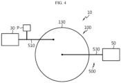
- FIG. 1 is a diagram showing a slurry filtering device 10 according to an embodiment of the present disclosure
- FIG. 2 is a projection of the slurry filtering device 10 of FIG. 1
- FIG. 3 is a top view of the slurry filtering device 10 of FIG. 2
- FIG. 4 is a bottom view of the slurry filtering device 10 of FIG. 2 .
- the slurry filtering device 10 may include a housing 100, a filter 300 and a slurry transport line 500.
- the housing 100 may include a slurry accommodation portion 110.
- the housing 100 may be cylindrical in shape, but the shape is not limited thereto.
- a slurry (not shown) may be supplied to the slurry accommodation portion 110.
- the slurry may be a coating material that is applied to a substrate.
- the substrate may be a separator that constitutes a part of an electrode assembly of a secondary battery.
- the present disclosure is not limited to the coating of the slurry on the separator.
- the slurry accommodation portion 110 may form a plurality of divided spaces.
- the slurry may be supplied to the plurality of divided spaces in a sequential order. Additionally, the plurality of divided spaces may be independent of each other.
- the filter 300 may be received in each of the plurality of divided spaces, and configured to filter at least some of particles in the slurry.
- the filter 300 may be a cylindrical cartridge filter, but is not limited thereto.
- the filter 300 may have at least one pore H on the surface thereof. Additionally, the slurry may be fed into the filter 300 through the pore H.
- the slurry supplied to the divided spaces of the slurry accommodation portion 110 may be fed into the filter 300 through the pore H.
- the slurry may include impurities and macroparticles.
- the filter 300 may remove the impurities and macroparticles from the slurry. Specifically, the impurities and macroparticles in the slurry may remain in the filter 300 after they pass through the pore H. To this end, the filter 300 may have a filtering material (not shown) of nanofibers therein.
- the filter 300 may have an outlet (not shown) through which the filtered slurry exits.
- the outlet may be formed in at least one of an upper side or a lower side of the filter 300.
- the filter 300 may be configured to filter all or some of the particles in the slurry according to the characteristics of the substrate. In an example, in case that the coating of the substrate is required to include impurities and macroparticles, the filter 300 may be configured to filter only some of the particles in the slurry.
- the slurry transport line 500 may be connected to a slurry supply portion 30 to receive the slurry and may be used to discharge the slurry filtered through the slurry filtering device 10 to a slurry discharge container 50.
- the slurry may be supplied from the slurry supply portion 30 to the slurry transport line 500 by a pumping force of a supply pump P.
- the slurry supply portion 30 and the slurry discharge container 50 may be equipped in a form of a pressure tank.
- the slurry transport line 500 may connect the plurality of divided spaces. Additionally, the slurry transport line 500 may be configured to supply the slurry to each divided space in a sequential order.
- the filter 300 may be received in each of the plurality of divided spaces, and the slurry transport line 500 may be configured to supply the slurry to each divided space in a sequential order to allow the filter 300 in each divided space to filter the slurry.
- the filters 300 received in the plurality of divided spaces may be connected in series by the slurry transport line 500 to filter the slurry in a sequential order.
- the outlets of the filters 300 may be connected to the slurry transport line 500.
- each filter 300 since the plurality of filters 300 is received in the independent spaces within the limited space, and each filter 300 is connected in series to filter the slurry in a sequential order, it may be possible to increase the slurry filtering time and improve the slurry filtering efficiency.
- the plurality of divided spaces may be hermetically separated by a plurality of partitions S.
- each filter 300 is received in the independent space by the plurality of partitions S, it may be possible to filter the slurry in a sequential order.
- the housing 100 may further include a slurry transport line accommodation portion 130.
- the slurry transport line accommodation portion 130 may be disposed on a side (for example, a lower side) of the slurry accommodation portion 110, and configured to receive the slurry transport line 500 in a space that is separated from the slurry accommodation portion 110.
- the slurry transport line accommodation portion 130 may be an empty space to easily accommodate the slurry transport line 500.
- the slurry transport line 500 and the filters 300 may be disposed in each independent space, it may be possible to prevent a decrease in slurry filtering effect caused by interferences of the slurry transport line 500 and the filters 300.
- the divided space of the slurry accommodation portion 110 at the exit of the slurry transport line 500 may be surrounded by the other divided spaces of the slurry accommodation portion 110.
- the divided space arrangement of the slurry accommodation portion 110 as described above may make it possible to apply the plurality of filters 300 in the limited space and form a more compact structure.
- the divided space of the slurry accommodation portion 110 at the exit of the slurry transport line 500 may be disposed at the center of the slurry accommodation portion 110.
- the divided space of the slurry accommodation portion 110 at the exit of the slurry transport line 500 may be cylindrical in shape.
- the divided space of the slurry accommodation portion 110 in cylindrical shape may be surrounded by the other divided spaces of the slurry accommodation portion 110 while being in close contact with the other divided spaces of the slurry accommodation portion 110.
- the exit of the slurry accommodation portion 110 may be disposed at the center of the slurry accommodation portion 110, it may be possible to reduce the size of the housing 100 for more compact design.
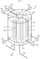
- FIG. 5 is a diagram exemplarily showing the filter 300 of the slurry filtering device 10 of FIG. 2 .
- FIG. 5(a) is a diagram showing the filter 300 at the exit of the slurry transport line 500
- FIG. 5(b) is a diagram showing the filter 300 at the entrance of the slurry transport line 500.
- the slurry transport line 500 may be configured to supply the slurry to each divided space of the slurry accommodation portion 110 in a sequential order.
- the pores H of the filters 300 are larger in size, it may be possible to remove the macroparticles in the slurry more effectively, but the pores H of the filters 300 may be frequently clogged by the macroparticles, resulting in short replacement intervals of the filters 300.
- the plurality of filters 300 may have different pore H sizes.
- each filter 300 is connected in series and the slurry is supplied to each divided space and each filter 300 in a sequential order, different pore H sizes of the filters 300 do not greatly affect the time required to filter the slurry and the slurry filtering efficiency.
- the plurality of filters 300 is configured to have different pore H sizes, it may be possible to improve the durability of the filter 300.
- the slurry may be supplied to the slurry transport line 500 by the pumping force of the supply pump P. Accordingly, the slurry supply pressure may decrease as it goes from the divided space at the entrance of the slurry transport line 500 to the divided space at the exit of the slurry transport line 500.
- the supply pressure of the slurry supplied to the divided space at the entrance of the slurry transport line 500 may be highest. Additionally, the supply pressure of the slurry supplied to the divided space at the exit of the slurry transport line 500 may be lowest.
- the pore H size of the plurality of filters 300 may change as it goes from the entrance of the slurry transport line 500 to the exit of the slurry transport line 500.
- the pore H size of the plurality of filters 300 may decrease from the entrance of the slurry transport line 500 to the exit of the slurry transport line 500.
- the pore H size of the filter 300 at the exit of the slurry transport line 500 may be smallest. Additionally, as shown in FIG. 5(b) , the pore H size of the filter 300 at the entrance of the slurry transport line 500 may be largest.
- the filters 300 may be configured to filter smaller particles in the slurry in a sequential order toward the divided space of the slurry accommodation portion 110 at the exit of the slurry transport line 500.
- the pore H size of the remaining filter 300 except the filter 300 at the entrance of the slurry transport line 500 is smaller, it may be possible to improve the durability of the filter 300 and reduce the time required to replace the filter 300.
- FIG. 6 is a diagram schematically showing slurry filtering in the slurry filtering device 10 of FIG. 2 (specifically, FIG. 6 is a cross-sectional view of FIG. 2 , taken along the line A-A'), and FIG. 7 is a diagram showing a slurry flow pathway in the slurry filtering device 10 of FIG. 2 (specifically, FIG. 7 is a projection of the slurry filtering device 10, when viewed from the bottom of FIG. 2 ).
- the particles in the slurry filtered through the filters 300 may be indicated by 'W' in FIG. 6 by way of illustration.
- the slurry transport line 500 may include an entrance line 510, an exit line 530 and a connection line 550.
- the entrance line 510 may be configured to connect the slurry supply portion 30 to the divided space of the slurry accommodation portion 110 at the entrance of the slurry transport line 500.
- the supply pump P may be connected to the entrance line 510, and the slurry may be supplied from the slurry supply portion 30 to the entrance line 510 by the pumping force of the supply pump P.
- the exit line 530 may be configured to connect the slurry discharge container 50 to the filter 300 at the exit of the slurry transport line 500.
- connection line 550 may be disposed in the slurry transport line accommodation portion 130 and configured to connect the plurality of divided spaces.
- connection line 550 connecting each divided space is disposed in the space that is separated from the slurry accommodation portion 110, it may be possible to prevent a decrease in slurry filtering effect caused by interferences of the connection line 550 and the filters 300.
- connection line 550 may be configured to connect the filter 300 received in one divided space to a side (for example, a lower side) of the adjacent other divided space. In this instance, the connection line 550 may be connected to the outlets of the filters 300.
- the slurry fed into the first divided space through the entrance line 510 may be filtered through the first filter 300 received in the first divided space.
- the particles in the slurry may be filtered by the filters 300 as shown in FIG. 6 .
- the slurry filtered through the first filter 300 may be supplied to the side of the adjacent other divided space through the first connection line 550.
- connection line 550 may connect the filter 300 received in one divided space to the side of the adjacent other divided space. Accordingly, it may be possible to easily filter the slurry in a sequential order through the filters 300 received in the divided spaces.
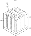
- FIG. 8 is a diagram showing a slurry filtering device 12 according to another embodiment of the present disclosure.
- the slurry filtering device 12 according to another embodiment of the present disclosure is shown.
- the slurry filtering device 12 according to this embodiment is similar to the slurry filtering device 10 of the previous embodiment, and the redundant description of substantially the identical or similar components to the previous embodiment is omitted, and the following description is made based on difference(s) between this embodiment and the previous embodiment.
- the slurry filtering device 12 may include the housing 100.
- the housing 100 of the slurry filtering device 12 may have a polygonal cross section, not a circular cross section, in the horizontal plane.
- the cross section of the slurry filtering device 12 in the horizontal plane may be square-shaped as shown in FIG. 8 .
- the slurry filtering device 12 may include the housing 100 in more diverse shapes depending on the working environment. That is, it may be possible to place a larger number of filters 300 in the housing 100 that may be configured in more diverse shapes of horizontal cross section when the working environment space is more available.
- FIG. 9 is a diagram showing a slurry filtering device 14 according to still another embodiment of the present disclosure.
- the slurry filtering device 14 according to still another embodiment of the present disclosure is shown.
- the slurry filtering device 14 according to this embodiment is similar to the slurry filtering device 10 of the previous embodiment, and the redundant description of substantially the identical or similar components to the previous embodiment is omitted, and the following description is made based on difference(s) between this embodiment and the previous embodiment.
- the slurry filtering device 14 may include a pressure adjustment portion 700.
- the pressure adjustment portion 700 may be configured to individually adjust the pressure in the plurality of divided spaces of the slurry accommodation portion 110.
- the pressure adjustment portion 700 may be a vacuum pump, but is not limited thereto.
- the pressure adjustment portion 700 may be individually connected to each divided space. Accordingly, it may be possible to change the filtering efficiency of the filter 300 in each divided space.
- the slurry filtering device 14 may easily adjust the filtering efficiency of the filter 300 in each divided space as per a user's request.
- each filter 300 is received in the independent spaces within the limited space, and each filter 300 is connected in series to filter the slurry in a sequential order, it may be possible to increase the slurry filtering time and improve the slurry filtering efficiency.
Landscapes
- Chemical & Material Sciences (AREA)
- Chemical Kinetics & Catalysis (AREA)
- Engineering & Computer Science (AREA)
- Electrochemistry (AREA)
- General Chemical & Material Sciences (AREA)
- Manufacturing & Machinery (AREA)
- Materials Engineering (AREA)
- Filtration Of Liquid (AREA)
Abstract
Description
- The present disclosure relates to a slurry filtering device, and more particularly, to a slurry filtering device with improved filtering efficiency.
- The present application claims priority to
Korean Patent Application No. 10-2022-0043450 filed on April 7, 2022 - With the technology development and growing demand for mobile devices, the demand for secondary batteries as an energy source is sharply increasing, and a secondary battery essentially comprises an electrode assembly as a power generation element.
- The electrode assembly may be formed into a predetermined shape by coating an electrode active material slurry on a positive electrode current collector and a negative electrode current collector to manufacture a positive electrode and a negative electrode, and stacking the positive electrode and the negative electrode on two sides of a separator. Additionally, the secondary battery may be formed by receiving the electrode assembly in a battery case, injecting an electrolyte and sealing up.
- The separator that constitutes a part of the electrode assembly may be formed by coating a coating slurry containing a mixture of a polymer binder, a dispersant, heat resistant filters or the like on one or two surfaces of a substrate.
- The separator may be coated with a coating material having an adhesive strength on the surface. In this instance, the coating material may be a mixture of inorganic particles and a binder polymer. Here, the inorganic particles may improve thermal safety of the separator. That is, the inorganic particles may prevent the separator from shrinking at high temperature. Additionally, the binder polymer may immobilize the inorganic particles. By the inorganic particles, a coating layer on the separator surface may have a predetermined pore structure. The pore structure may allow ions to smoothly move from the positive electrode to the negative electrode though the inorganic particles are coated on the separator. Additionally, the binder polymer may stably hold the inorganic particles onto the separator, thereby improving mechanical stability of the separator. Further, the binder polymer may adhere the separator to the electrode more stably (such a coating is referred to as Safety Reinforced Separator (SRS) coating).
- To stably manufacture the separator, a slurry filtering device is used to remove impurities or macroparticles from the slurry when preparing the coating slurry.
- The slurry filtering device needs one filter in one housing, and in case that different types of filters are connected in series, it is necessary replace and clean the filter for each housing, causing inconvenience, resulting in low work efficiency.
- The present disclosure is designed to solve the above-described problem, and therefore the present disclosure is directed to providing a slurry filtering device with improved slurry filtering efficiency.
- However, the technical problem of the present disclosure is not limited to the above-described problem, and these and other problems will be clearly understood by those skilled in the art from the following description.
- A slurry filtering device according to an embodiment of the present disclosure includes a housing including a slurry accommodation portion inside to which a slurry is supplied, a plurality of filters received respectively in a plurality of divided spaces of the slurry accommodation portion and configured to filter at least some of particles in the slurry, and a slurry transport line connecting the plurality of divided spaces to supply the slurry to each divided space in a sequential order.
- Preferably, the plurality of divided spaces may be hermetically separated by a plurality of partitions.
- Preferably, the housing may further include a slurry transport line accommodation portion at a side of the slurry accommodation portion, the slurry transport line accommodation portion accommodating the slurry transport line in a space that is separated from the slurry accommodation portion.
- Preferably, the divided space of the slurry accommodation portion at an exit of the slurry transport line may be surrounded by the other divided spaces of the slurry accommodation portion.
- Preferably, the divided space of the slurry accommodation portion at the exit of the slurry transport line may be disposed at a center of the slurry accommodation portion.
- Preferably, the plurality of filters may have different pore sizes.
- Preferably, the pore size of the plurality of filters may decrease as it goes from an entrance of the slurry transport line to an exit of the slurry transport line.
- Preferably, the slurry transport line may include an entrance line connecting a slurry supply portion to the divided space of the slurry accommodation portion at an entrance of the slurry transport line, an exit line connecting a slurry discharge container to the filter at an exit of the slurry transport line, and a connection line disposed in the slurry transport line accommodation portion, the connection line connecting the plurality of divided spaces.
- Preferably, the connection line may be configured to connect the filter received in one divided space to a side of the adjacent other divided space.
- Preferably, the slurry filtering device may further include a pressure adjustment portion configured to individually adjust a pressure in the plurality of divided spaces.
- According to an embodiment of the present disclosure, since the plurality of filters is received in independent spaces within the limited space, and each filter is connected in series to filter the slurry in a sequential order, it may be possible to increase the slurry filtering time and improve the slurry filtering efficiency.
- Additionally, according to an embodiment of the present disclosure, since the slurry transport line and the filters are disposed in independent spaces, it may be possible to prevent a decrease in slurry filtering effect caused by interferences of the slurry transport line and the filters.
- Additionally, according to an embodiment of the present disclosure, it may be possible to apply multiple filters in the limited space and form a more compact structure.
- Additionally, according to an embodiment of the present disclosure, since the plurality of filters has different pore sizes, it may be possible to improve durability of the filter.
- Additionally, according to an embodiment of the present disclosure, it may be possible to filter macroparticles in the slurry at the divided space of the slurry accommodation portion at the entrance of the slurry transport line of the highest slurry supply pressure.
- Additionally, according to an embodiment of the present disclosure, since the remaining filter except the filter at the entrance of the slurry transport line has a smaller pore size, it may be possible to improve the durability of the filter and reduce the time required to replace the filter.
- These and other effects may be achieved by the embodiments of the present disclosure. The effects of the present disclosure will be described in detail in each embodiment, or a description of effects that can be easily understood by those skilled in the art is omitted.
- The accompanying drawings illustrate an exemplary embodiment of the present disclosure and together with the foregoing disclosure, serve to provide further understanding of the technical aspect of the present disclosure, and thus, the present disclosure is not construed as being limited to the drawings.
-
FIG. 1 is a diagram showing a slurry filtering device according to an embodiment of the present disclosure. -
FIG. 2 is a projection of the slurry filtering device ofFIG. 1 . -
FIG. 3 is a top view of the slurry filtering device ofFIG. 2 . -
FIG. 4 is a bottom view of the slurry filtering device ofFIG. 2 . -
FIG. 5 is a diagram exemplarily showing a filter of the slurry filtering device ofFIG. 2 . -
FIG. 6 is a diagram schematically showing slurry filtering in the slurry filtering device ofFIG. 2 . -
FIG. 7 is a diagram showing a slurry flow pathway in the slurry filtering device ofFIG. 2 . -
FIG. 8 is a diagram showing a slurry filtering device according to another embodiment of the present disclosure. -
FIG. 9 is a diagram showing a slurry filtering device according to still another embodiment of the present disclosure. - Hereinafter, exemplary embodiments of the present disclosure will be described in detail with reference to the accompanying drawings. Prior to the description, it should be understood that the terms or words used in the specification and the appended claims should not be construed as limited to general and dictionary meanings, but rather interpreted based on the meanings and concepts corresponding to technical aspects of the present disclosure on the basis of the principle that the inventor is allowed to define terms appropriately for the best explanation.
- Therefore, the embodiments described herein and the illustration in the drawings are provided by way of illustration to describe the technical aspect of the present disclosure and not intended to be limiting, so it should be understood that a variety of equivalents and modifications could have been made thereto at the time that the application was filed.
-
FIG. 1 is a diagram showing aslurry filtering device 10 according to an embodiment of the present disclosure,FIG. 2 is a projection of theslurry filtering device 10 ofFIG. 1 ,FIG. 3 is a top view of theslurry filtering device 10 ofFIG. 2 , andFIG. 4 is a bottom view of theslurry filtering device 10 ofFIG. 2 . - Referring to
FIGS. 1 to 4 , theslurry filtering device 10 according to an embodiment of the present disclosure may include ahousing 100, afilter 300 and aslurry transport line 500. - The
housing 100 may include aslurry accommodation portion 110. In an example, thehousing 100 may be cylindrical in shape, but the shape is not limited thereto. - A slurry (not shown) may be supplied to the
slurry accommodation portion 110. The slurry may be a coating material that is applied to a substrate. In an example, the substrate may be a separator that constitutes a part of an electrode assembly of a secondary battery. However, the present disclosure is not limited to the coating of the slurry on the separator. - The
slurry accommodation portion 110 may form a plurality of divided spaces. The slurry may be supplied to the plurality of divided spaces in a sequential order. Additionally, the plurality of divided spaces may be independent of each other. - The
filter 300 may be received in each of the plurality of divided spaces, and configured to filter at least some of particles in the slurry. In an embodiment, thefilter 300 may be a cylindrical cartridge filter, but is not limited thereto. - The
filter 300 may have at least one pore H on the surface thereof. Additionally, the slurry may be fed into thefilter 300 through the pore H. - Specifically, the slurry supplied to the divided spaces of the
slurry accommodation portion 110 may be fed into thefilter 300 through the pore H. Additionally, the slurry may include impurities and macroparticles. - In this instance, the
filter 300 may remove the impurities and macroparticles from the slurry. Specifically, the impurities and macroparticles in the slurry may remain in thefilter 300 after they pass through the pore H. To this end, thefilter 300 may have a filtering material (not shown) of nanofibers therein. - Additionally, the
filter 300 may have an outlet (not shown) through which the filtered slurry exits. In an example, the outlet may be formed in at least one of an upper side or a lower side of thefilter 300. - The
filter 300 may be configured to filter all or some of the particles in the slurry according to the characteristics of the substrate. In an example, in case that the coating of the substrate is required to include impurities and macroparticles, thefilter 300 may be configured to filter only some of the particles in the slurry. - The
slurry transport line 500 may be connected to aslurry supply portion 30 to receive the slurry and may be used to discharge the slurry filtered through theslurry filtering device 10 to aslurry discharge container 50. In this instance, the slurry may be supplied from theslurry supply portion 30 to theslurry transport line 500 by a pumping force of a supply pump P. Additionally, theslurry supply portion 30 and theslurry discharge container 50 may be equipped in a form of a pressure tank. - More details of the
slurry transport line 500 will be given in the following related description. - The
slurry transport line 500 may connect the plurality of divided spaces. Additionally, theslurry transport line 500 may be configured to supply the slurry to each divided space in a sequential order. - Specifically, the
filter 300 may be received in each of the plurality of divided spaces, and theslurry transport line 500 may be configured to supply the slurry to each divided space in a sequential order to allow thefilter 300 in each divided space to filter the slurry. - That is, the
filters 300 received in the plurality of divided spaces may be connected in series by theslurry transport line 500 to filter the slurry in a sequential order. In this instance, the outlets of thefilters 300 may be connected to theslurry transport line 500. - According to the exemplary configuration of the present disclosure, since the plurality of
filters 300 is received in the independent spaces within the limited space, and eachfilter 300 is connected in series to filter the slurry in a sequential order, it may be possible to increase the slurry filtering time and improve the slurry filtering efficiency. - Hereinafter, the
housing 100, thefilter 300 and theslurry transport line 500 will be described in more detail. - Referring to
FIGS. 1 to 4 again, the plurality of divided spaces may be hermetically separated by a plurality of partitions S. - Accordingly, it may be possible to prevent the slurry supplied to one divided space from entering the adjacent other divided space without filtering by the
filter 300. - Additionally, since each
filter 300 is received in the independent space by the plurality of partitions S, it may be possible to filter the slurry in a sequential order. - The
housing 100 may further include a slurry transportline accommodation portion 130. - The slurry transport
line accommodation portion 130 may be disposed on a side (for example, a lower side) of theslurry accommodation portion 110, and configured to receive theslurry transport line 500 in a space that is separated from theslurry accommodation portion 110. In this instance, the slurry transportline accommodation portion 130 may be an empty space to easily accommodate theslurry transport line 500. - Accordingly, since the
slurry transport line 500 and thefilters 300 may be disposed in each independent space, it may be possible to prevent a decrease in slurry filtering effect caused by interferences of theslurry transport line 500 and thefilters 300. - Referring to
FIGS. 1 to 4 again, the divided space of theslurry accommodation portion 110 at the exit of theslurry transport line 500 may be surrounded by the other divided spaces of theslurry accommodation portion 110. - According to the exemplary configuration of the present disclosure, in the structure in which the slurry is sequentially supplied to each divided space accommodating the
filter 300, the divided space arrangement of theslurry accommodation portion 110 as described above may make it possible to apply the plurality offilters 300 in the limited space and form a more compact structure. - In particular, the divided space of the
slurry accommodation portion 110 at the exit of theslurry transport line 500 may be disposed at the center of theslurry accommodation portion 110. - In an example, as shown in
FIGS. 1 to 4 , in case that the cross section of thehousing 100 in the horizontal plane is circular in shape, the divided space of theslurry accommodation portion 110 at the exit of theslurry transport line 500 may be cylindrical in shape. In this instance, the divided space of theslurry accommodation portion 110 in cylindrical shape may be surrounded by the other divided spaces of theslurry accommodation portion 110 while being in close contact with the other divided spaces of theslurry accommodation portion 110. - According to the exemplary configuration of the present disclosure, since the exit of the
slurry accommodation portion 110 may be disposed at the center of theslurry accommodation portion 110, it may be possible to reduce the size of thehousing 100 for more compact design. -
FIG. 5 is a diagram exemplarily showing thefilter 300 of theslurry filtering device 10 ofFIG. 2 . In this instance,FIG. 5(a) is a diagram showing thefilter 300 at the exit of theslurry transport line 500, andFIG. 5(b) is a diagram showing thefilter 300 at the entrance of theslurry transport line 500. - Referring to
FIGS. 1 to 5 , theslurry transport line 500 may be configured to supply the slurry to each divided space of theslurry accommodation portion 110 in a sequential order. - In this instance, as the pores H of the
filters 300 are larger in size, it may be possible to remove the macroparticles in the slurry more effectively, but the pores H of thefilters 300 may be frequently clogged by the macroparticles, resulting in short replacement intervals of thefilters 300. - In an embodiment of the present disclosure, the plurality of
filters 300 may have different pore H sizes. - As described above, since each
filter 300 is connected in series and the slurry is supplied to each divided space and eachfilter 300 in a sequential order, different pore H sizes of thefilters 300 do not greatly affect the time required to filter the slurry and the slurry filtering efficiency. - When the plurality of
filters 300 is configured to have different pore H sizes, it may be possible to improve the durability of thefilter 300. - As described above, the slurry may be supplied to the
slurry transport line 500 by the pumping force of the supply pump P. Accordingly, the slurry supply pressure may decrease as it goes from the divided space at the entrance of theslurry transport line 500 to the divided space at the exit of theslurry transport line 500. - That is, the supply pressure of the slurry supplied to the divided space at the entrance of the
slurry transport line 500 may be highest. Additionally, the supply pressure of the slurry supplied to the divided space at the exit of theslurry transport line 500 may be lowest. - In an embodiment of the present disclosure, the pore H size of the plurality of
filters 300 may change as it goes from the entrance of theslurry transport line 500 to the exit of theslurry transport line 500. - More specifically, the pore H size of the plurality of
filters 300 may decrease from the entrance of theslurry transport line 500 to the exit of theslurry transport line 500. - That is, as shown in
FIG. 5(a) , the pore H size of thefilter 300 at the exit of theslurry transport line 500 may be smallest. Additionally, as shown inFIG. 5(b) , the pore H size of thefilter 300 at the entrance of theslurry transport line 500 may be largest. - According to the exemplary configuration of the present disclosure, it may be possible to filter the macroparticles in the slurry by the
filter 300 in the divided space of theslurry accommodation portion 110 at the entrance of theslurry transport line 500 having the highest slurry supply pressure. Additionally, thefilters 300 may be configured to filter smaller particles in the slurry in a sequential order toward the divided space of theslurry accommodation portion 110 at the exit of theslurry transport line 500. - Additionally, since the pore H size of the remaining
filter 300 except thefilter 300 at the entrance of theslurry transport line 500 is smaller, it may be possible to improve the durability of thefilter 300 and reduce the time required to replace thefilter 300. -
FIG. 6 is a diagram schematically showing slurry filtering in theslurry filtering device 10 ofFIG. 2 (specifically,FIG. 6 is a cross-sectional view ofFIG. 2 , taken along the line A-A'), andFIG. 7 is a diagram showing a slurry flow pathway in theslurry filtering device 10 ofFIG. 2 (specifically,FIG. 7 is a projection of theslurry filtering device 10, when viewed from the bottom ofFIG. 2 ). In this instance, the particles in the slurry filtered through thefilters 300 may be indicated by 'W' inFIG. 6 by way of illustration. - Referring to
FIGS. 1 to 7 , theslurry transport line 500 may include anentrance line 510, anexit line 530 and aconnection line 550. - The
entrance line 510 may be configured to connect theslurry supply portion 30 to the divided space of theslurry accommodation portion 110 at the entrance of theslurry transport line 500. - In this instance, the supply pump P may be connected to the
entrance line 510, and the slurry may be supplied from theslurry supply portion 30 to theentrance line 510 by the pumping force of the supply pump P. - The
exit line 530 may be configured to connect theslurry discharge container 50 to thefilter 300 at the exit of theslurry transport line 500. - The
connection line 550 may be disposed in the slurry transportline accommodation portion 130 and configured to connect the plurality of divided spaces. - As shown in
FIGS. 6 and7 , since theconnection line 550 connecting each divided space is disposed in the space that is separated from theslurry accommodation portion 110, it may be possible to prevent a decrease in slurry filtering effect caused by interferences of theconnection line 550 and thefilters 300. - The
connection line 550 may be configured to connect thefilter 300 received in one divided space to a side (for example, a lower side) of the adjacent other divided space. In this instance, theconnection line 550 may be connected to the outlets of thefilters 300. - Specifically, referring to
FIGS. 6 and7 , the slurry fed into the first divided space through theentrance line 510 may be filtered through thefirst filter 300 received in the first divided space. In this instance, the particles in the slurry may be filtered by thefilters 300 as shown inFIG. 6 . - Subsequently, the slurry filtered through the
first filter 300 may be supplied to the side of the adjacent other divided space through thefirst connection line 550. - The
connection line 550 may connect thefilter 300 received in one divided space to the side of the adjacent other divided space. Accordingly, it may be possible to easily filter the slurry in a sequential order through thefilters 300 received in the divided spaces. -
FIG. 8 is a diagram showing aslurry filtering device 12 according to another embodiment of the present disclosure. - Referring to
FIG. 8 , theslurry filtering device 12 according to another embodiment of the present disclosure is shown. Theslurry filtering device 12 according to this embodiment is similar to theslurry filtering device 10 of the previous embodiment, and the redundant description of substantially the identical or similar components to the previous embodiment is omitted, and the following description is made based on difference(s) between this embodiment and the previous embodiment. - Referring to
FIG. 8 , theslurry filtering device 12 may include thehousing 100. - The
housing 100 of theslurry filtering device 12 according to this embodiment may have a polygonal cross section, not a circular cross section, in the horizontal plane. - In an example, the cross section of the
slurry filtering device 12 in the horizontal plane may be square-shaped as shown inFIG. 8 . - The
slurry filtering device 12 according to this embodiment may include thehousing 100 in more diverse shapes depending on the working environment. That is, it may be possible to place a larger number offilters 300 in thehousing 100 that may be configured in more diverse shapes of horizontal cross section when the working environment space is more available. -
FIG. 9 is a diagram showing aslurry filtering device 14 according to still another embodiment of the present disclosure. - Referring to
FIG. 9 , theslurry filtering device 14 according to still another embodiment of the present disclosure is shown. Theslurry filtering device 14 according to this embodiment is similar to theslurry filtering device 10 of the previous embodiment, and the redundant description of substantially the identical or similar components to the previous embodiment is omitted, and the following description is made based on difference(s) between this embodiment and the previous embodiment. - Referring to
FIG. 9 , theslurry filtering device 14 may include apressure adjustment portion 700. - In the
slurry filtering device 14 according to this embodiment, thepressure adjustment portion 700 may be configured to individually adjust the pressure in the plurality of divided spaces of theslurry accommodation portion 110. In an example, thepressure adjustment portion 700 may be a vacuum pump, but is not limited thereto. - The
pressure adjustment portion 700 may be individually connected to each divided space. Accordingly, it may be possible to change the filtering efficiency of thefilter 300 in each divided space. - The
slurry filtering device 14 according to this embodiment may easily adjust the filtering efficiency of thefilter 300 in each divided space as per a user's request. - As described above, according to an embodiment of the present disclosure, since the plurality of
filters 300 is received in the independent spaces within the limited space, and eachfilter 300 is connected in series to filter the slurry in a sequential order, it may be possible to increase the slurry filtering time and improve the slurry filtering efficiency. - While the present disclosure has been hereinabove described with regard to a limited number of embodiments and drawings, the present disclosure is not limited thereto and it is obvious to those skilled in the art that a variety of modifications and changes may be made thereto within the technical aspect of the present disclosure and the scope of the appended claims and equivalents thereof.
- The terms indicating directions such as upper, lower, left, right, front and rear are used for convenience of description, but it is obvious to those skilled in the art that the terms may change depending on the position of the stated element or an observer.
-
- 10, 12, 14: Slurry filtering device
- 30: Slurry supply portion
- P: Supply pump
- 50: Slurry discharge container
- 100: Housing
- 110: Slurry accommodation portion
- S: Partition
- 130: Slurry transport line accommodation portion
- 300: Filter
- H: Pore
- 500: Slurry transport line
- 510: Entrance line
- 530: Exit line
- 550: Connection line
- 700: Pressure adjustment portion
Claims (10)
- A slurry filtering device, comprising:a housing including a slurry accommodation portion inside to which a slurry is supplied;a plurality of filters received respectively in a plurality of divided spaces of the slurry accommodation portion, and configured to filter at least some of particles in the slurry; anda slurry transport line connecting the plurality of divided spaces to supply the slurry to each divided space in a sequential order.
- The slurry filtering device according to claim 1, wherein the plurality of divided spaces is hermetically separated by a plurality of partitions.
- The slurry filtering device according to claim 1, wherein the housing further includes a slurry transport line accommodation portion at a side of the slurry accommodation portion, the slurry transport line accommodation portion accommodating the slurry transport line in a space that is separated from the slurry accommodation portion.
- The slurry filtering device according to claim 1, wherein the divided space of the slurry accommodation portion at an exit of the slurry transport line is surrounded by the other divided spaces of the slurry accommodation portion.
- The slurry filtering device according to claim 4, wherein the divided space of the slurry accommodation portion at the exit of the slurry transport line is disposed at a center of the slurry accommodation portion.
- The slurry filtering device according to claim 1, wherein the plurality of filters has different pore sizes.
- The slurry filtering device according to claim 6, wherein the pore size of the plurality of filters decreases as it goes from an entrance of the slurry transport line to an exit of the slurry transport line.
- The slurry filtering device according to claim 3, wherein the slurry transport line includes:an entrance line connecting a slurry supply portion to the divided space of the slurry accommodation portion at an entrance of the slurry transport line;an exit line connecting a slurry discharge container to the filter at an exit of the slurry transport line; anda connection line disposed in the slurry transport line accommodation portion, the connection line connecting the plurality of divided spaces.
- The slurry filtering device according to claim 8, wherein the connection line is configured to connect the filter received in one divided space to a side of the adjacent other divided space.
- The slurry filtering device according to claim 1, further comprising:
a pressure adjustment portion configured to individually adjust a pressure in the plurality of divided spaces.
Applications Claiming Priority (2)
| Application Number | Priority Date | Filing Date | Title |
|---|---|---|---|
| KR1020220043450A KR20230144323A (en) | 2022-04-07 | 2022-04-07 | Slurry filtering device |
| PCT/KR2023/004676 WO2023195804A1 (en) | 2022-04-07 | 2023-04-06 | Slurry filtering device |
Publications (3)
| Publication Number | Publication Date |
|---|---|
| EP4391099A1 true EP4391099A1 (en) | 2024-06-26 |
| EP4391099A4 EP4391099A4 (en) | 2025-01-15 |
| EP4391099B1 EP4391099B1 (en) | 2026-04-29 |
Family
ID=88243209
Family Applications (1)
| Application Number | Title | Priority Date | Filing Date |
|---|---|---|---|
| EP23785028.4A Active EP4391099B1 (en) | 2022-04-07 | 2023-04-06 | Slurry filtering device |
Country Status (6)
| Country | Link |
|---|---|
| US (1) | US20250269305A1 (en) |
| EP (1) | EP4391099B1 (en) |
| JP (1) | JP7775461B2 (en) |
| KR (1) | KR20230144323A (en) |
| CN (1) | CN117836962A (en) |
| WO (1) | WO2023195804A1 (en) |
Family Cites Families (10)
| Publication number | Priority date | Publication date | Assignee | Title |
|---|---|---|---|---|
| DE19734588A1 (en) * | 1997-08-09 | 1999-02-11 | Boll & Kirch Filter | Backwashing filter |
| US6080313A (en) * | 1997-08-29 | 2000-06-27 | Kelada; Maher I. | Point-of-use water purification system with a cascade ion exchange option |
| US6027647A (en) * | 1998-05-20 | 2000-02-22 | Northcut; Donald A. | Multi-element liquid filter system with flushing and filtering circuits |
| DE10024401A1 (en) * | 2000-05-19 | 2001-11-22 | Boll & Kirch Filter | Reversible flow filter for lubricant oil; has open filter elements at each end of filter casing around rotating shaft and cleaning unit moved by shaft to clean filter elements during reverse flow |
| US6423223B1 (en) | 2000-08-31 | 2002-07-23 | Donald A. Northcut | Multi-element, reverse osmosis, liquid filter system with flushing and filtering circuits |
| US6521124B2 (en) * | 2000-08-31 | 2003-02-18 | Donald A. Northcut | Reverse osmosis liquid filter system with ultraviolet filtration |
| KR101126502B1 (en) * | 2009-10-19 | 2012-03-29 | 주식회사 케이씨텍 | Filtering apparatus |
| US20210308604A1 (en) * | 2020-04-01 | 2021-10-07 | Stonehouse Innovations, LLC | Fluid treatment system having concentric chambers |
| DE102020131637A1 (en) * | 2020-05-22 | 2021-11-25 | Taiwan Semiconductor Manufacturing Co., Ltd. | FILTER DEVICE FOR THE PROCESS OF MANUFACTURING SEMICONDUCTOR DEVICES |
| KR102514610B1 (en) | 2020-09-29 | 2023-03-27 | 주식회사 코펙 | Corrosion-resistant enamel composition applicable to corrosion-resistant steel |
-
2022
- 2022-04-07 KR KR1020220043450A patent/KR20230144323A/en active Pending
-
2023
- 2023-04-06 EP EP23785028.4A patent/EP4391099B1/en active Active
- 2023-04-06 CN CN202380013219.2A patent/CN117836962A/en active Pending
- 2023-04-06 WO PCT/KR2023/004676 patent/WO2023195804A1/en not_active Ceased
- 2023-04-06 US US18/854,453 patent/US20250269305A1/en active Pending
- 2023-04-06 JP JP2024519913A patent/JP7775461B2/en active Active
Also Published As
| Publication number | Publication date |
|---|---|
| EP4391099A4 (en) | 2025-01-15 |
| WO2023195804A1 (en) | 2023-10-12 |
| US20250269305A1 (en) | 2025-08-28 |
| JP7775461B2 (en) | 2025-11-25 |
| CN117836962A (en) | 2024-04-05 |
| JP2024535484A (en) | 2024-09-30 |
| KR20230144323A (en) | 2023-10-16 |
| EP4391099B1 (en) | 2026-04-29 |
Similar Documents
| Publication | Publication Date | Title |
|---|---|---|
| JP6543632B2 (en) | Bipolar plate structure using a nonconductive forehead frame | |
| CN108028419B (en) | Longitudinal Constraints for Energy Storage Devices | |
| CA2811875C (en) | Lithium accumulator | |
| ES2776800T3 (en) | Electrode material, redox flow battery electrode and redox flow battery | |
| EP3859849A1 (en) | Flow battery and method of making the flow battery | |
| EP3550635B1 (en) | Battery module and battery pack including the same | |
| EP1471590A1 (en) | Fuel battery and electric device | |
| KR102073853B1 (en) | Secondary battery module improved in cooling passage and frame assembly for the same | |
| KR101643036B1 (en) | Apparatus of manufacturing electrode assembly | |
| KR102140483B1 (en) | Distribution plate for sofc and sofc having the same | |
| CN106575785A (en) | Battery Cells and Redox Flow Batteries | |
| CN103119749A (en) | Battery cell modules, batteries and motor vehicles | |
| EP4391099A1 (en) | Slurry filtering device | |
| US20240030475A1 (en) | Electrochemical Cell, More Particularly of a Redox Flow Battery, and Corresponding Cell Stack | |
| KR20150033130A (en) | Coating apparatus having slot-die | |
| CN220774608U (en) | Battery module housing and battery pack | |
| US9698445B2 (en) | Storage element including multiple lithium cells | |
| JP6776107B2 (en) | Flow battery cell stack and flow battery | |
| CN213752776U (en) | Battery pole piece lamination machine with dustproof construction | |
| CN115485893A (en) | Redox flow battery | |
| CN215869666U (en) | Coupling assembling and battery module | |
| US20250300301A1 (en) | Battery cell holder, battery module, and battery pack | |
| EP4611158A1 (en) | Battery pack | |
| KR20240098832A (en) | Electrolyte supply apparatus | |
| JP2024527280A (en) | Structurally integrated electrochemical cells and structurally integrated stacks constructed from said electrochemical cells - Patents.com |
Legal Events
| Date | Code | Title | Description |
|---|---|---|---|
| STAA | Information on the status of an ep patent application or granted ep patent |
Free format text: STATUS: THE INTERNATIONAL PUBLICATION HAS BEEN MADE |
|
| PUAI | Public reference made under article 153(3) epc to a published international application that has entered the european phase |
Free format text: ORIGINAL CODE: 0009012 |
|
| STAA | Information on the status of an ep patent application or granted ep patent |
Free format text: STATUS: REQUEST FOR EXAMINATION WAS MADE |
|
| 17P | Request for examination filed |
Effective date: 20240319 |
|
| AK | Designated contracting states |
Kind code of ref document: A1 Designated state(s): AL AT BE BG CH CY CZ DE DK EE ES FI FR GB GR HR HU IE IS IT LI LT LU LV MC ME MK MT NL NO PL PT RO RS SE SI SK SM TR |
|
| A4 | Supplementary search report drawn up and despatched |
Effective date: 20241217 |
|
| RIC1 | Information provided on ipc code assigned before grant |
Ipc: B01D 29/52 20060101ALI20241211BHEP Ipc: B01D 29/11 20060101ALI20241211BHEP Ipc: H01M 4/139 20100101ALI20241211BHEP Ipc: H01M 4/04 20060101AFI20241211BHEP |
|
| STAA | Information on the status of an ep patent application or granted ep patent |
Free format text: STATUS: EXAMINATION IS IN PROGRESS |
|
| DAV | Request for validation of the european patent (deleted) | ||
| DAX | Request for extension of the european patent (deleted) | ||
| 17Q | First examination report despatched |
Effective date: 20250702 |
|
| GRAP | Despatch of communication of intention to grant a patent |
Free format text: ORIGINAL CODE: EPIDOSNIGR1 |
|
| STAA | Information on the status of an ep patent application or granted ep patent |
Free format text: STATUS: GRANT OF PATENT IS INTENDED |
|
| INTG | Intention to grant announced |
Effective date: 20251210 |
|
| GRAS | Grant fee paid |
Free format text: ORIGINAL CODE: EPIDOSNIGR3 |
|
| P01 | Opt-out of the competence of the unified patent court (upc) registered |
Free format text: CASE NUMBER: UPC_APP_0004874_4391099/2026 Effective date: 20260211 |
|
| GRAA | (expected) grant |
Free format text: ORIGINAL CODE: 0009210 |
|
| STAA | Information on the status of an ep patent application or granted ep patent |
Free format text: STATUS: THE PATENT HAS BEEN GRANTED |
|
| AK | Designated contracting states |
Kind code of ref document: B1 Designated state(s): AL AT BE BG CH CY CZ DE DK EE ES FI FR GB GR HR HU IE IS IT LI LT LU LV MC ME MK MT NL NO PL PT RO RS SE SI SK SM TR |
|
| REG | Reference to a national code |
Ref country code: CH Ref legal event code: F10 Free format text: ST27 STATUS EVENT CODE: U-0-0-F10-F00 (AS PROVIDED BY THE NATIONAL OFFICE) Effective date: 20260429 |